

Intellinet 524629, 524643 User Manual

8-PORT /
16-PORT
RACKMOUNT
KVM SWITCH
USER
MANUAL
MODELS 524629
& 524643
INT-524629/524643-UM-0309-01
Shown: 16-Port, Model 524643
524629_524643_01_man.indd 1 3/9/09 9:22:10 AM
524629_524643_01_man.indd 2 3/9/09 9:22:10 AM
3
Thank you for purchasing this INTELLINET NETWORK SOLUTIONS™ Rackmount KVM Switch,
Model 524629 (8-Port) or Model 524643 (16-Port).
Designed for computer/server management on a central console in corporate, factory and
campus computing environments, it provides an on-screen display (OSD) for intuitive KVM
switching operations, and its cascading feature can help upscale the number of connected
computers. A dedicated controller is featured on each port to keep the mouse and keyboard
alive even when the switch isn’t powered on. Excellent video quality with minimal degradation
is guaranteed even when daisy-chained (up to 64 units for Model 524629 and up to 256 units
for Model 524643), and perfect keyboard/mouse emulation provides high compatibility with
PCs, servers and various operating systems.
The easy-to-follow instructions in this user manual help make setup and operation relatively
quick and simple, so you’ll also soon be enjoying the benets of these additional features:
• USB and PS/2 interface support on both console and PC side
• Computer selection and operation using front-panel push buttons, keyboard hotkeys and
OSD menu
• Hot Plug and Play: no need to shut down the KVM switch to attach or remove PCs
• Numerical display and LED indicators for easy bank/port status monitoring
• Supports 2048 x 1536 resolution
• Supports Microsoft and Logitech standard 5-key mice and compatible models
• Buzzer sound for hotkey and port switching conrmation
• Auto-Scan period programmable via OSD menu option
• Password protection
• Auto-logout timeout support
• 4-in-1 connection cable (505727) included — additional connection cables (505727, 505734
or 505840) required per port
• Lifetime Warranty
NOTE: Some screen and product images are modied to t the format of this manual.
FCC Statement
This device generates and uses radio frequency and may cause interference to radio and
television reception if not installed and used properly. This has been tested and found to comply
with the limits of a Class B computing device in accordance with the specications in Part 15
of the FCC Rules. These specications are designed to provide reasonable protection against
such interference in a residential installation. However, there is no guarantee that interference
will not occur in a particular installation. If this device does cause harmful interference to radio
or television reception, which can be determined by turning the device off and on, the user can
try to correct the interference by one or more of the following measures:
• Reorient or relocate the receiving antenna.
• Increase the separation between the device and receiver.
• Connect the computer to an outlet on a circuit different from that to which the receiver is
connected.
• Consult the dealer or an experienced radio/TV technician for help.
524629_524643_01_man.indd 3 3/9/09 9:22:10 AM
4
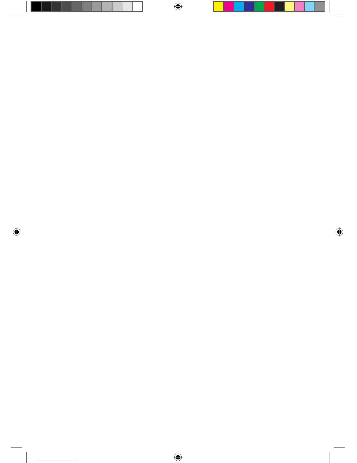
1 2 3 4 5 6 7 8
Reset Power
Selected
On Line
Shown here: 8-Port, Model 524629
Shown here: 16-Por t, Model 524643
16 15 14 13
F/W
Upgrade
8 7 6 5
Console
DC 5V
INSTALLATION/SETUP
Front Panel
Selected LED — Lighted red indicates that the PC (or cascaded KVM switch) connected to the
corresponding rear-panel port (matching the numbered button beneath the LED) is selected.
Online LED — Lighted green indicates the corresponding PC (or cascaded switch) is ready
(connected but not selected).
Buttons — Press any button (1-8 for Model 524629, 1-16 for Model 524643) to select — or
switch to — the corresponding port/channel for operation. NOTE: See the Operation section
for hotkey and OSD alternatives to pressing a button if the front panel is out of reach or is
otherwise not easily accessible.
Reset — Press this recessed button (using a narrow/pointed object, such as a common pin)
to reset the system.
Power — Lighted green indicates the KVM Switch is powered on. NOTE: A 5 V DC, 2 A
external power adapter is included with this Rackmount KVM Switch.
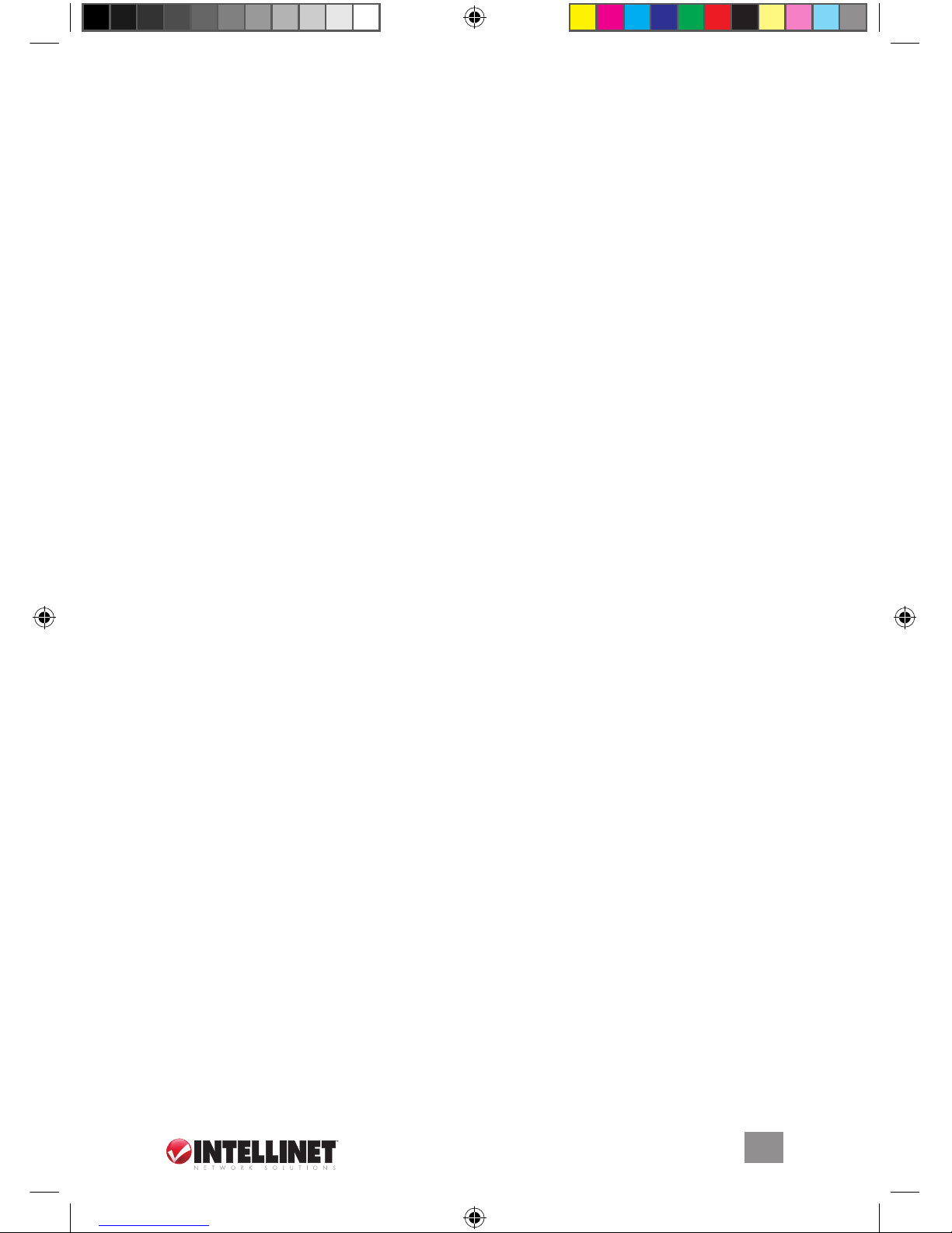
Rear Panel
DC 5V — Plug the included external power adapter into this jack and connect to an A/C outlet.
Conrm that the Power LED lights on the front panel. CAUTION:
• Before connecting to the KVM Switch, all computers should be powered off; otherwise, the
switch system might not be properly set up.
• For computers with a Keyboard Power On function, rst unplug the power cords; otherwise,
the switch system might not be properly set up.
• For some older computers to work with this switch’s USB interface, the USB setting must be
enabled in BIOS. (Refer to the computer’s instructions as needed.)
• For computers running Windows 98, use only PS/2 connections, as the OS doesn’t support
USB installation on the initial system startup.
F/W Upgrade — This mini-USB port connects the KVM Switch to a USB port on whichever
system computer is running a rmware update utility. (See Firmware Upgrades in the
Operation section.)
Console — Connect the console keyboard and mouse (USB or PS/2) and monitor (HD15) to
the console ports, using the device icons as guides, if needed.
Ports 1-8 / 1-16 — Use the included 4-in-1 connection cable,
Model 505727 — plus however many additional cables and/or
extenders you need — to connect the KVM Switch port(s)
to your computer(s) or cascading KVM switches.
524629_524643_01_man.indd 4 3/9/09 9:22:12 AM
5
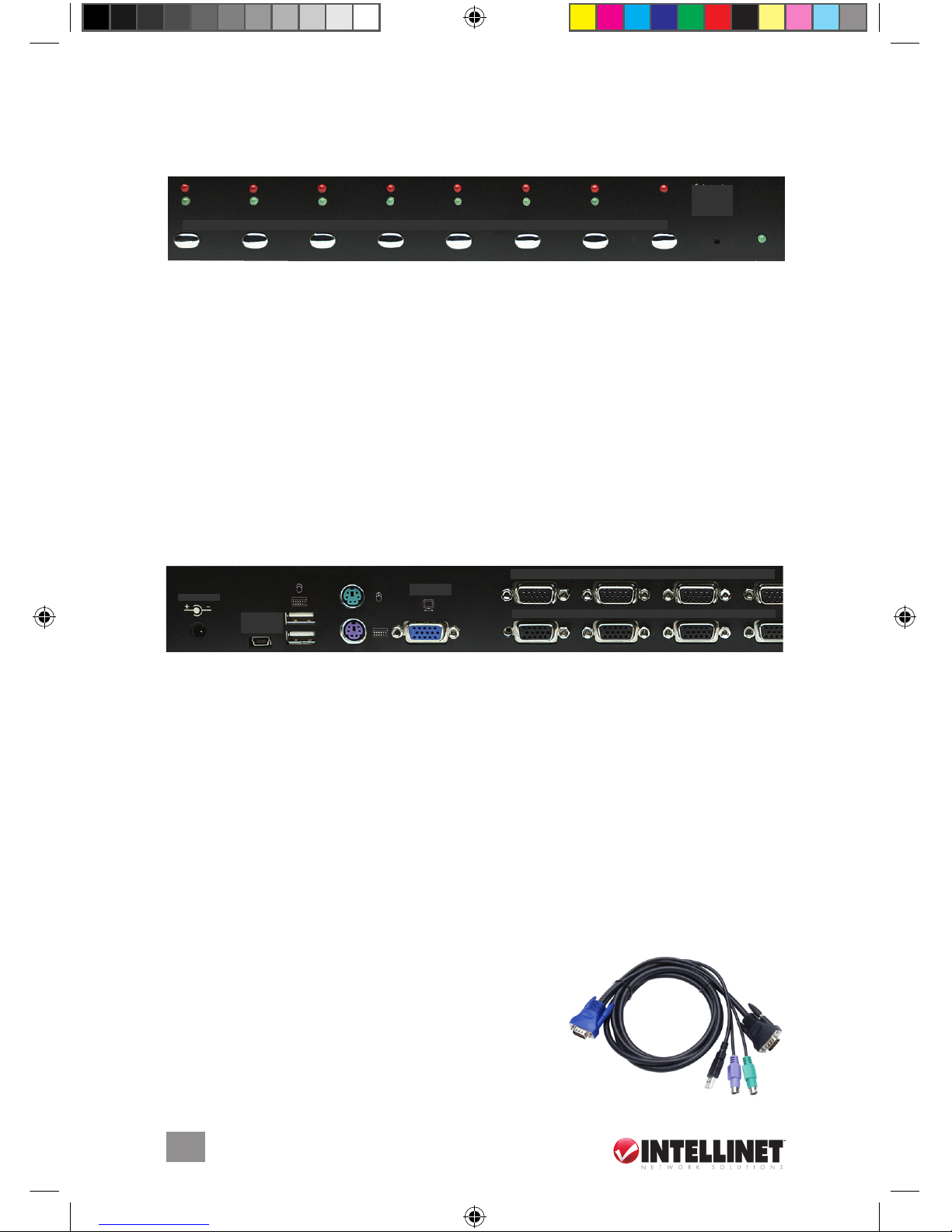
Single-Stage Installation
When you’re creating a switch system using only a
single KVM Switch, it can be connected to the
computer(s) three ways. CAUTION: As noted above,
before connecting to the KVM Switch, all computers
should be powered off; otherwise, the switch system
might not be properly set up.
• Connect the USB, PS/2 (keyboard/mouse) and VGA
connectors (A, B and C in the image at right).
NOTE: This is the recommended conguration.
• Connect only the PS/2 (keyboard/mouse) and VGA
connectors (B and C in the image at right).
• Connect only the USB and VGA connectors (A and
C in the image at right).
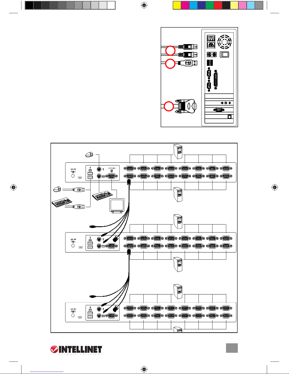
Cascade (Daisy-Chain) Installation
The Rackmount KVM Switch supports up to three “cascade” levels (in which additional switches
are connected, or “daisy-chained,” to the console-connected KVM switch as shown below),
B
A
C
524629_524643_01_man.indd 5 3/9/09 9:22:13 AM
 Loading...