

Page 1
soho
network
camera
user
manual
MODEL 524421
INT-524421-UM-1108-02
Page 2

2
TABLE OF CONTENTS
table of contents
INTRODUCTION ................................................................................................... 3
HARDWARE .......................................................................................................... 4
Camera ............................................................................................................ 4
Mounting Bracket/Stand ................................................................................... 4
Cables .............................................................................................................. 4
INSTALLATION/SETUP ......................................................................................... 5
So ft war e ........................................................................................................... 5
OPER ATION .......................................................................................................... 5
Using the Camera with a Windows Web Browser ............................................ 5
Using the Camera with a Mac Web Browser .................................................... 6
Using the Camera with an iPhone .................................................................... 6
Using the Camera with a Mobile/Cell Phone .................................................... 7
Using the Camera with MSN Messenger ......................................................... 8
Main Menu ......................................................................................................11
Setting / Basic ................................................................................................ 13
Sy ste m ........................................................................................................ 13
Camera ....................................................................................................... 16
Ne tw ork ....................................................................................................... 20
Se cur it y ....................................................................................................... 27
Setting / Advanced ......................................................................................... 29
FTP Client ................................................................................................... 29
SM TP .......................................................................................................... 31
HTTP Event ................................................................................................. 35
Schedule ..................................................................................................... 36
Motion Detection ......................................................................................... 37
System Log ................................................................................................. 38
FRAME RATE & BIT RATE TABLES ................................................................... 39
STORAGE REQUIREMENT TABLES ..................................................................41
SPECIFICATIONS ............................................................................................... 42
section page
Page 3

3
INTRODUCTION
introduction
Thank you for purchasing the INTELLINET NETWORK SOLUTIONS™
SOHO Network Camera, Model 524421.
Offering the latest technology and many of today’s most popular features,
this camera presents the versatility and reliability that makes it an ideal
choice for a wide variety of applications.
These easy-to-follow instructions make setup and operation quick and
simple, so you’ll also soon be enjoying the benets of these features:
• Excellent image quality with 30 fps full-motion video in all resolutions
• Progressive-scan image sensor with OmniPixel2 technology
• Audio support, full duplex, up to 8 kHz, with integrated microphone
• Easy-to-use 16-channel camera viewing and recording utility included
• Integrated multi-window motion detection
• Selectable video buffer for smoother video streaming
• Supports simultaneous MPEG4 and Motion-JPEG image compression
• Mobile phone streaming live video through 3GPP / ISMA / RTSP
• Mobile phone live image through 2.5 WAP
• MPEG4 + Motion-JPEG + 3GPP mobile phone streaming, audio and
10x digital zoom
• Supports HTTPS encryption for enhanced security
• Supports UPnP with UPnP port forwarding capability
• Ultra-compact and easy to install
• Lifetime Warranty
NOTE: Some screen images are modied to t the format of this manual.
PACKAGE CONTENTS
• SOHO Network Camera
• Camera mounting bracket
• Quick installation guide
• External power adapter
• Software CD
Page 4
4
HARDWARE
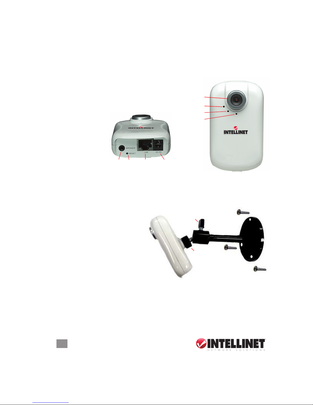
Focus Adjustment Ring
Built-in Microphone
Power LED
Network LED
Audio Out
(Speaker)
Reset Network
Connector
Power
Connector
Locking Bolt
Bracket
Connector
hardware
CAMERA
As identied below, camera components, indicators and connections
are self-explanatory except for the recessed Reset button, which can
be 1) pressed (with a common pin or similar pointed
object) and released to reboot the camera when
it’s powered on, or 2) pressed and
held in for 10 seconds to revert to
factory default settings.
MOUNTING BRACKET / STAND
For positioning the camera on a vertical surface (such as a wall or post)
or horizontal surface (such as a ceiling or overhead beam):
1. Attach the base of the mounting bracket to the at surface using the
three included screws.
2. Screw the bracket connector
into the back of the camera.
3. Loosen the locking bolt
enough to position the camera
as desired; tighten the locking
bolt to secure the camera in place.
CABLES
1. Use a standard RJ45 network cable to make your camera-to-LAN
connection.
2. Connect the included power adapter to the camera.
Page 5
5
INSTALLATION/SETUP
installation/setup
SYSTEM REQUIREMENTS
For normal operation and viewing of the SOHO Network Camera, it’s
recommended that your system meet these minimum requirements for
proper operation:
• Pentium 4 1600 MHz (or equivalent AMD) CPU
• 64 MB RAM graphic cards (or equivalent on-board graphic cards)
• 512 MB
• Windows 2000 or later; Mac OS X (Leopard)
• Internet Explorer 6 or later Web browser
SOFTWARE
1. With your computer on, insert the included software CD in the CD ROM drive. The setup screen will display automatically.
2. From the IP Camera Installation menu, select “Intelligent IP Installer”
and follow the subsequent on-screen instructions.
NOTE: Install “Xvid codec” when installing “Intelligent IP Installer” if you
can’t view the recorded video le (due to a missing video decoder). With
Windows 2000 Server, if the codec doesn’t work properly, download
Xvid codec 1.0 from the Internet.
oper ation
Using the Camera with a Windows Web Browser
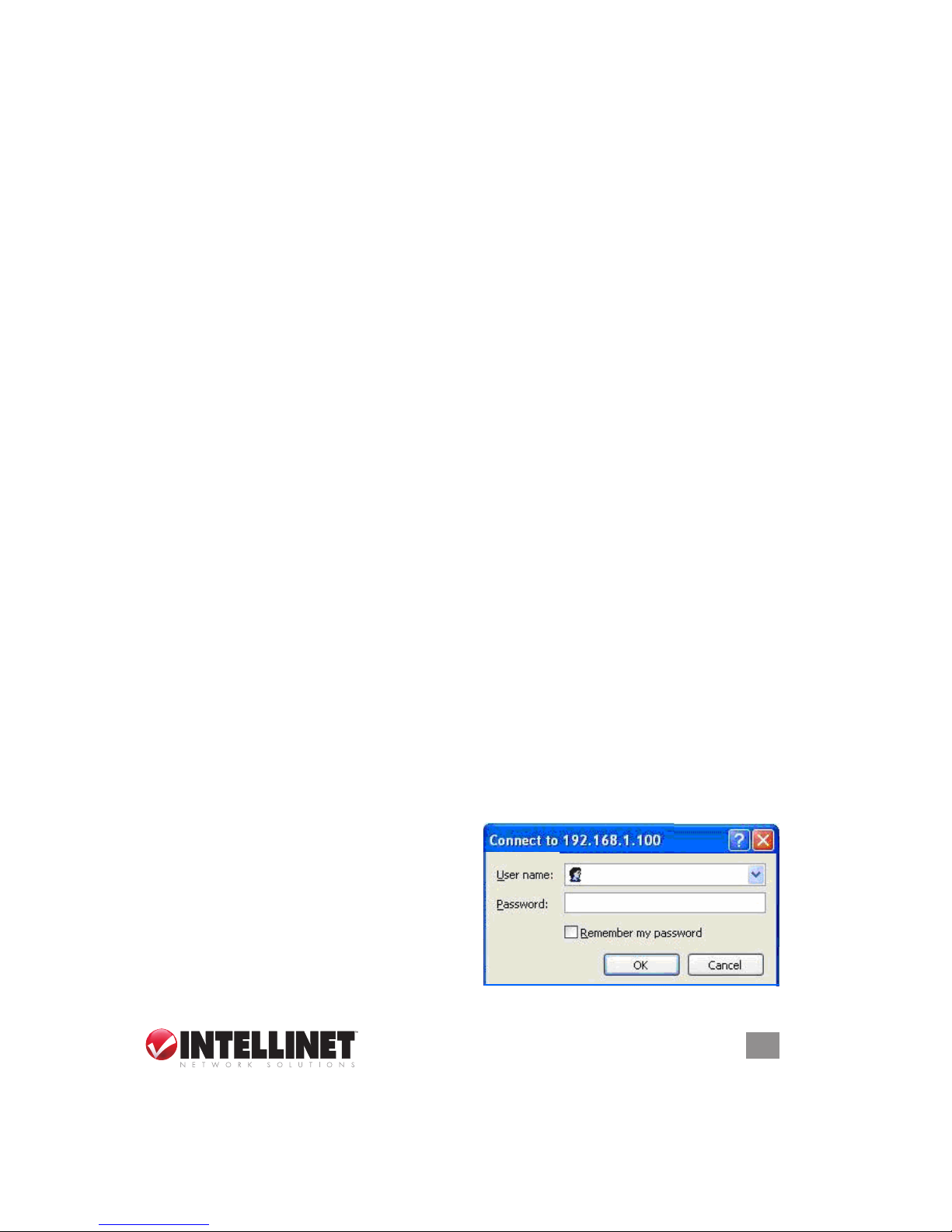
1. Open your Web browser, then enter the IP address or host name of the
SOHO Network Camera in the location/address eld. NOTE: If you
only want to view the video without accessing the Setting screen,
enter “http://<IP>/index2.htm” as your Web URL.
2. Enter the default name “admin”
and default password “admin.”
These are set at the factory for the
administrator and can be changed
in the Account section (Setting →
Basic → Security → Account). Click
“OK,” and the monitor image will
Page 6
6
OPERATION
display in your browser along with the Setting, Client Setting and
Image Setup menu options (see Main Menu section in this manual).
Using the Camera with a Mac Web Browser
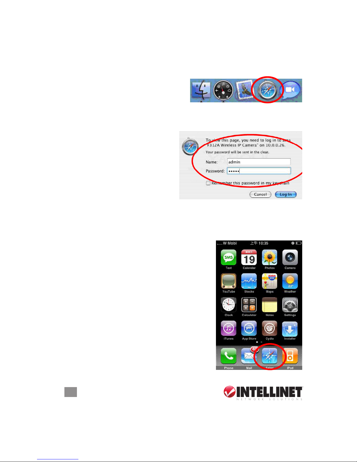
1. Click the Safari (browser) icon on
your desktop and enter the IP
address of the IP camera in the
Location / Address eld of your browser. NOTE: If you only want to
view the video without accessing the Setting screen, enter
“http://<IP>/index2.htm” as your Web URL.
2. Enter the default name “admin”
and default password “admin.”
These are set at the factory for
the administrator and can be
changed in the Account section
(Setting → Basic → Security
→ Account). Click “Log in,”
and the monitor image will .................................
display in your browser along with the Setting, Client Setting and
Image Setup menu options (see Main Menu section in this manual).
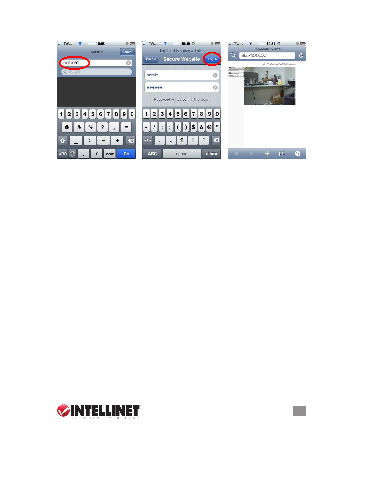
Using the Camera with an iPhone
1. Select the Safari function (right).
2. Enter the IP address in your Web link
(below left).
3. Enter a name and password (below
center; defaults are both “admin”). Press
“Log In.”
4. The menu and live image display in the
middle of the screen (below right).
NOTE: The iPhone will present continuous
snapshots, not real-time video streaming. The
recording feature, therefore, is disabled.
Page 7
7
OPERATION
Using the Camera with a Mobile/Cell Phone
To use the SOHO Network Camera through a mobile/cell phone, make
sure the Real Time Streaming Protocol (RTSP) is set to “On” (which is the
default setting: Setting → Basic → Camera → General).
3G MOBILE PHONE VIEWING/STREAMING
For 3G mobile phone viewing, enter “rtsp://<IP>:<PORT>/video.3gp” in
your 3G Streaming Link, where <IP> is the public IP address of your
camera and <PORT> is the RTSP port of your camera. The default
value for the port is 554. Example: rt sp: //10 0.10.10.1:85 54 /vi deo. 3gp.
NOTE: You can also use RTSP clients (RealPlayer, VLC, Quicktime,
etc.) to view RTSP streaming by entering “rtsp://<IP>:<PORT>/video.3gp”
as the player’s URL.
2.5G MOBILE PHONE WAP VIEWING
For 2.5G mobile phone viewing, enter “<IP>/mobile.wml” in your 2.5G
Web browser, where <IP> is the public IP address of your camera.
2.5G MOBILE PHONE BROWSER VIEWING
For 2.5G mobile phone viewing, enter “<IP>/mobile.htm” in your 2.5G
Web browser, where <IP> is the public IP address of your camera.
Page 8
8
OPERATION
Using the Camera with MSN Messenger
You can download free MSN software and create a new MSN account
(“camera at home” is the example used in this manual) to use Microsoft
Live Messenger.
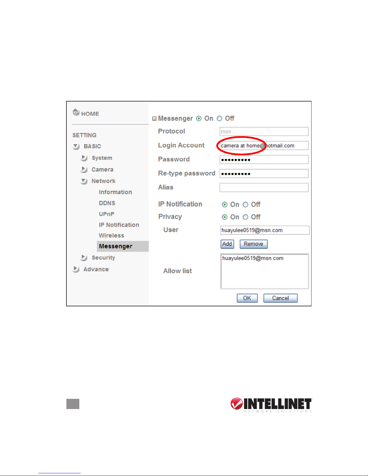
1. Go to Setting → Basic → Network → Messenger and refer to the
options below.
Messenger — Select “On” and ll in the Login Account (Camera at home)
and both Password elds.
IP Notication — Select “On” to have the camera send IP notications to
users with permission.
Privacy — Select “On” to create an allow list. Enter a username and click
“Add” for each address you want to allow access to.
2. Use your account to log in to the Messenger software. Then, add the
new MSN account (camera at home)
Page 9
9
OPERATION
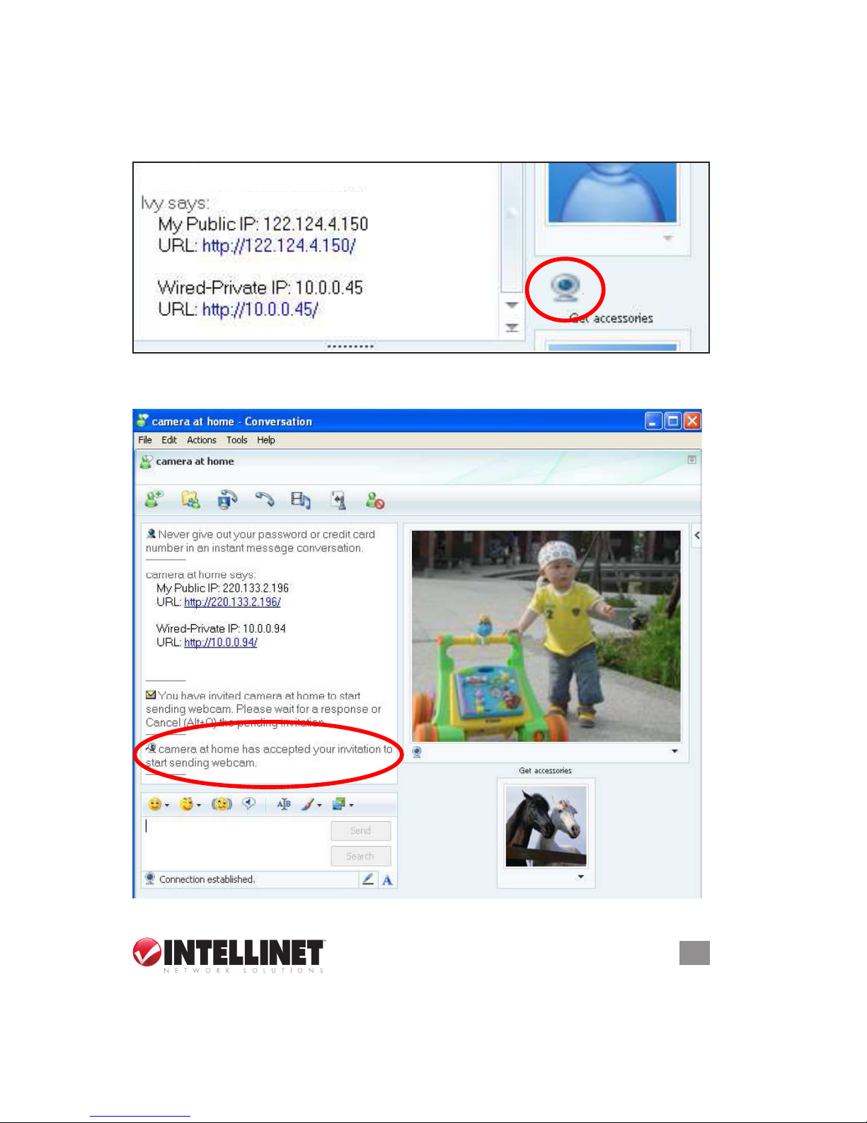
3. Camera at home will display with its public IP and private IP if the IP
Notication option is selected.
4. Click the camera icon and select “View a new contact’s webcam.”
5. The camera will “accept your invitation” and display the live video in
the right screen after few seconds.
Camera at home says:
http://220.133.2.196/ <[email protected]>
Page 10
10
OPERATION
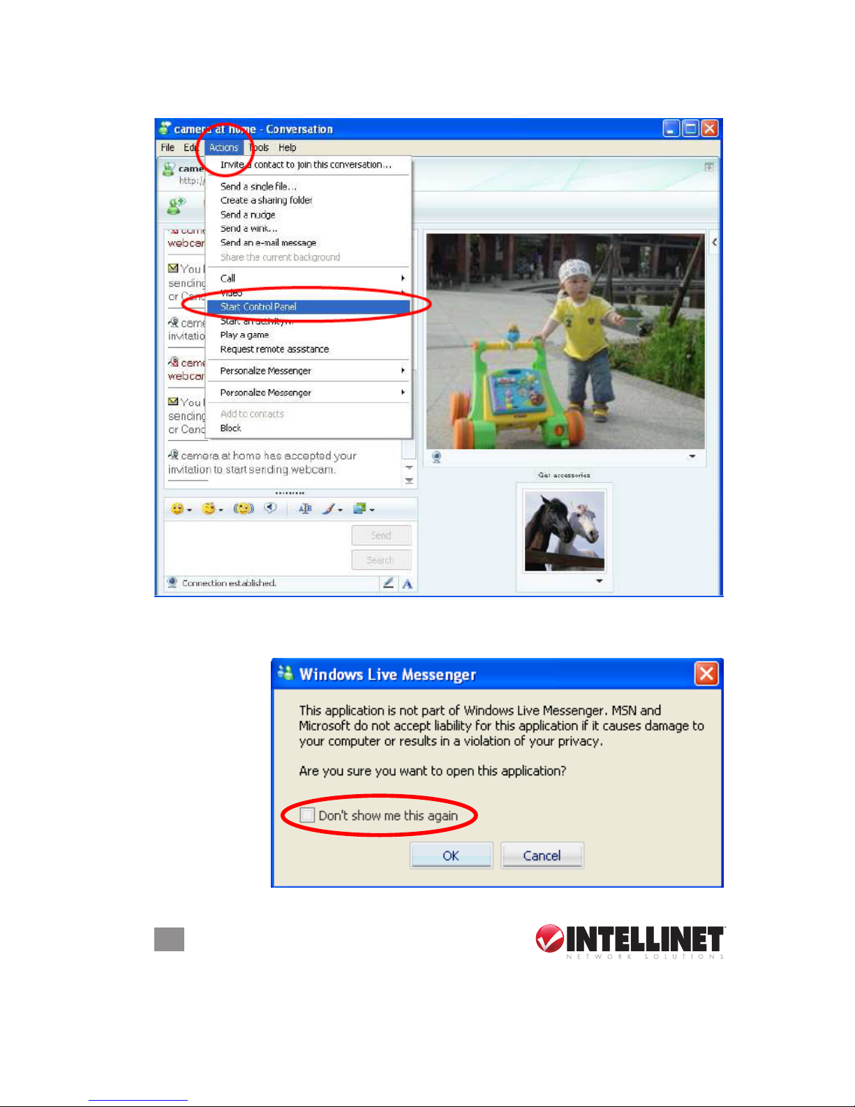
6. Open the Actions menu and select “Start Control Panel.”
Main Menu
7. A message displays stating “This application is not part of Windows
Live Messenger....” Select “Don’t show me this again” and click “OK.”
Page 11

11
OPERATION
8. When the Control Panel screen displays, you have several options:
• Click the camera/ snapshot icon to instantly send the image being
viewed.
• Click the paint/pallete icon to display the tool bar for setting up an
image: Brightness, Contrast, Saturation and Hue.
• After adjustments have been made, you can still click “Default” to
return to the previous settings.
Main Menu
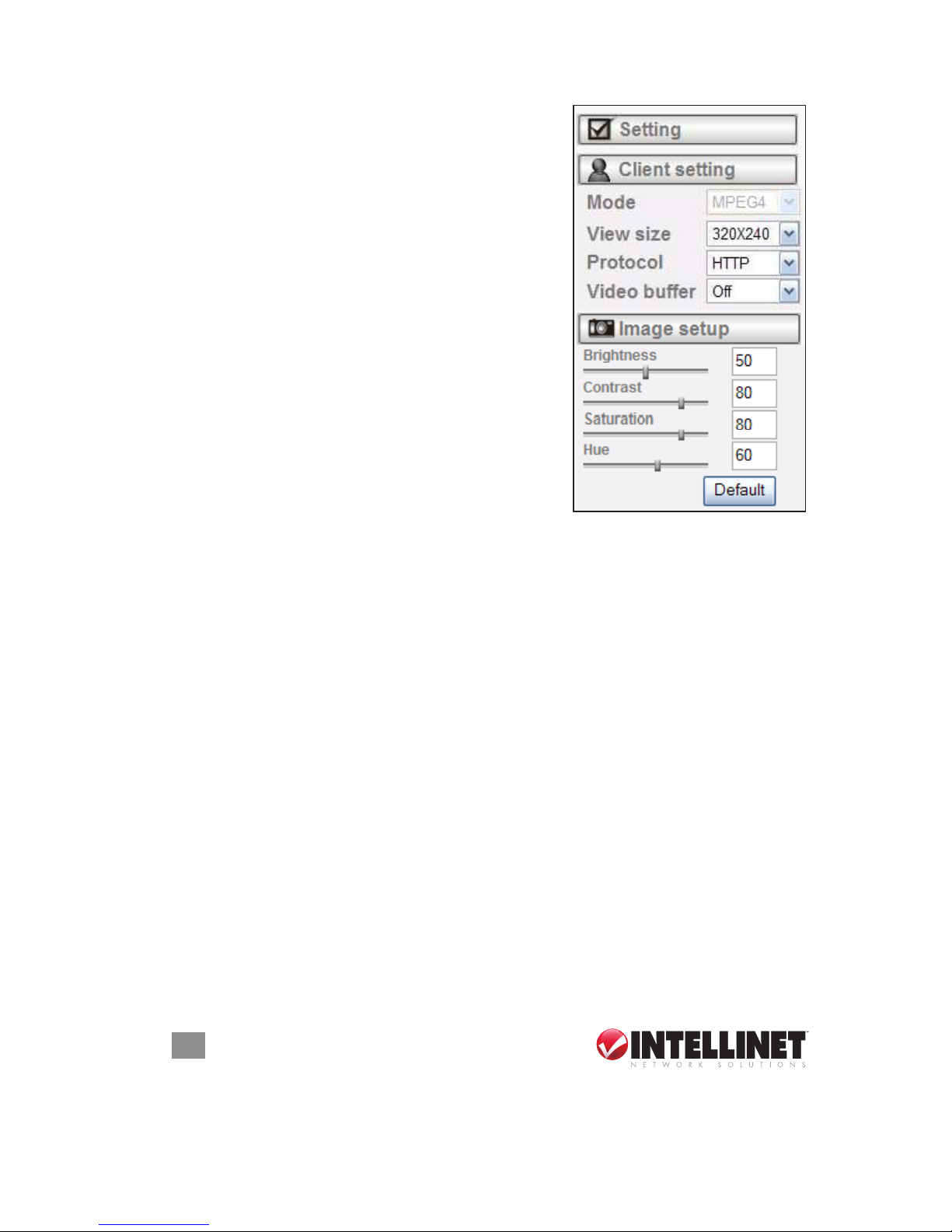
The main conguration screen displays the initial menu options for all the
camera settings: Setting, Client Setting and Image Setup on the left; Live
View options attached to the image on the right.
SETTING
If acting as the administrator, click to access the Basic and Advanced
settings menus (each explained in detail in separate sections below).
CLIENT SETTING
Click to access settings for the client(s).
Mode — From the pull-down menu, choose between MPEG4 and
http://2 20.133.2.196/ <bu cs_fan@hotm ail.com>
Page 12
12
OPERATION
MJPEG video compression modes.
NOTE: MJPEG streaming is unavailable
if RTSP mode is activated.
View Size — Select the desired display
image resolution: 640 x 480 or 320 x 240.
Protocol — Select the transfer protocol:
TCP, UDP, HTTP or Multicast.
Video Buffer — This makes the streaming
smoother in unsteady network
environments, but might cause a slight
delay in live viewing.
IMAGE SETUP
Use the slide-bars to adjust the levels: lower
to the left, high to the right.
Brightness — The higher the value, the
brighter the image.
Contrast — This is the ratio of white to
black produced by the system. The higher the value, the more dened
the image.
Saturation — This is determined by a combination of light intensity and
how much it’s distributed across the spectrum of different wavelengths.
The higher the value, the more colorful the image.
Hue — This is one of the three main attributes of perceived color,
affected by different wavelengths of color. The higher the value, the
more vivid the image.
Click “Default” to return to previous settings.
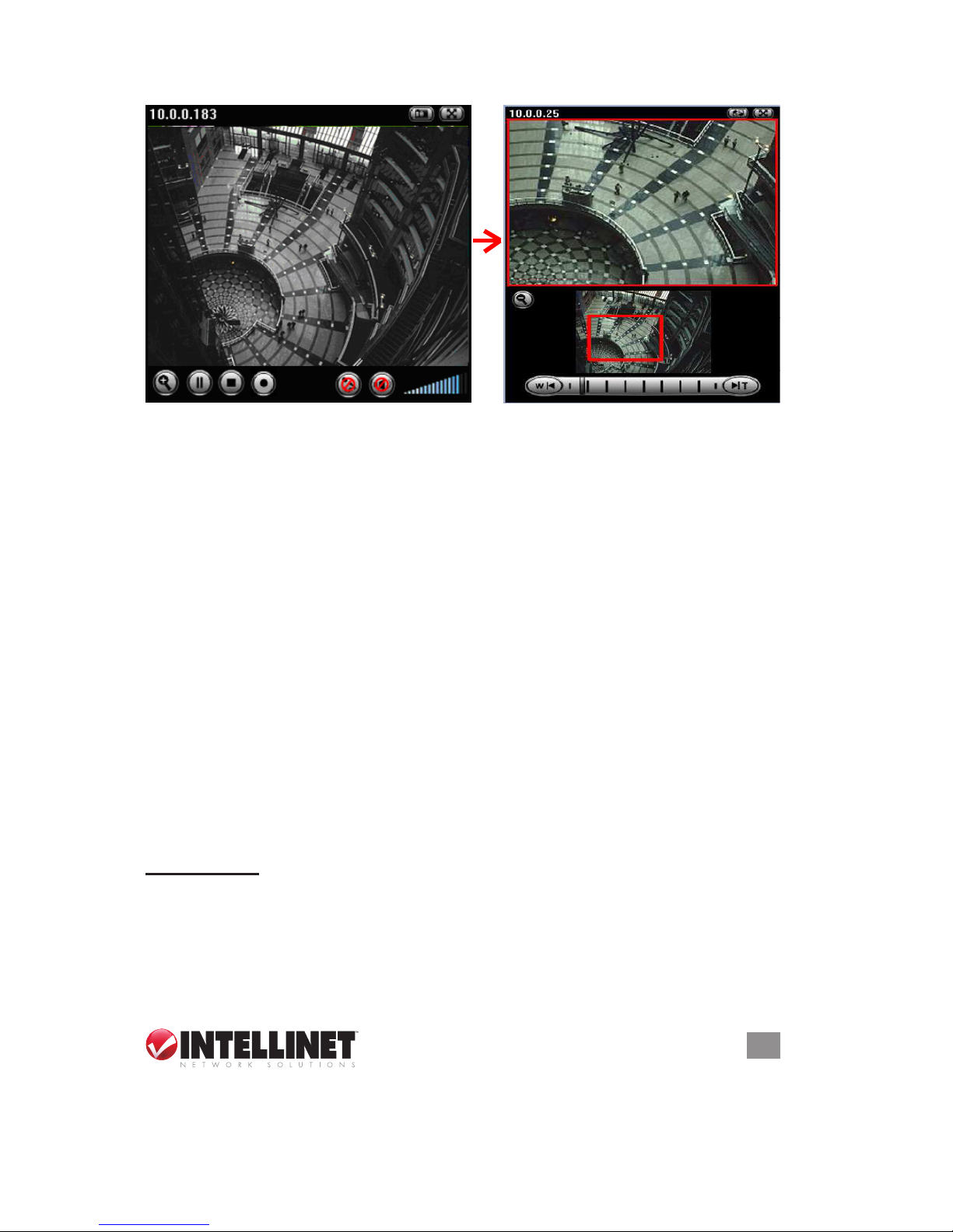
LIVE VIEW
The buttons and bars at the top and bottom of the image control the
following options.
Snapshot — To capture a still image and save it in your computer:
1. Click the camera icon (0) and a snapshot window will appear.
2. Click “Save” to save the picture in your computer.
3. Click “Close” to return to the view page.
Zoom — To display the digital zoom, click the zoom button (1). To adjust
the zoom range, move the slide-bar control (2). To position the red
view frame (3), left-click and drag your mouse.
Page 13
13
OPERATION
Audio buttons — Click on the speaker button (4) to turn the speakers
on/off. Click on the microphone button (5) to turn the microphone
on/off. The volume control bar (6) indicates the loudness level.
NOTE: When the speaker button is clicked “on,” the speakers on
your computer are turned on to transmit sound from the connected
camera(s). Likewise, when the microphone button is clicked “on,” it
means you can broadcast to the connected camera(s) via the
Ethernet using your microphone.
Video buttons — Click to pause the current video (7); to stop/play (8);
or to record (9).
Setting / Basic
From the Main menu, go to Setting, then Basic to access the System,
Camera, Network and Security submenus.
SYSTEM
Go to this menu to display and congure settings on the Information,
Date/Time and Initialize screens.
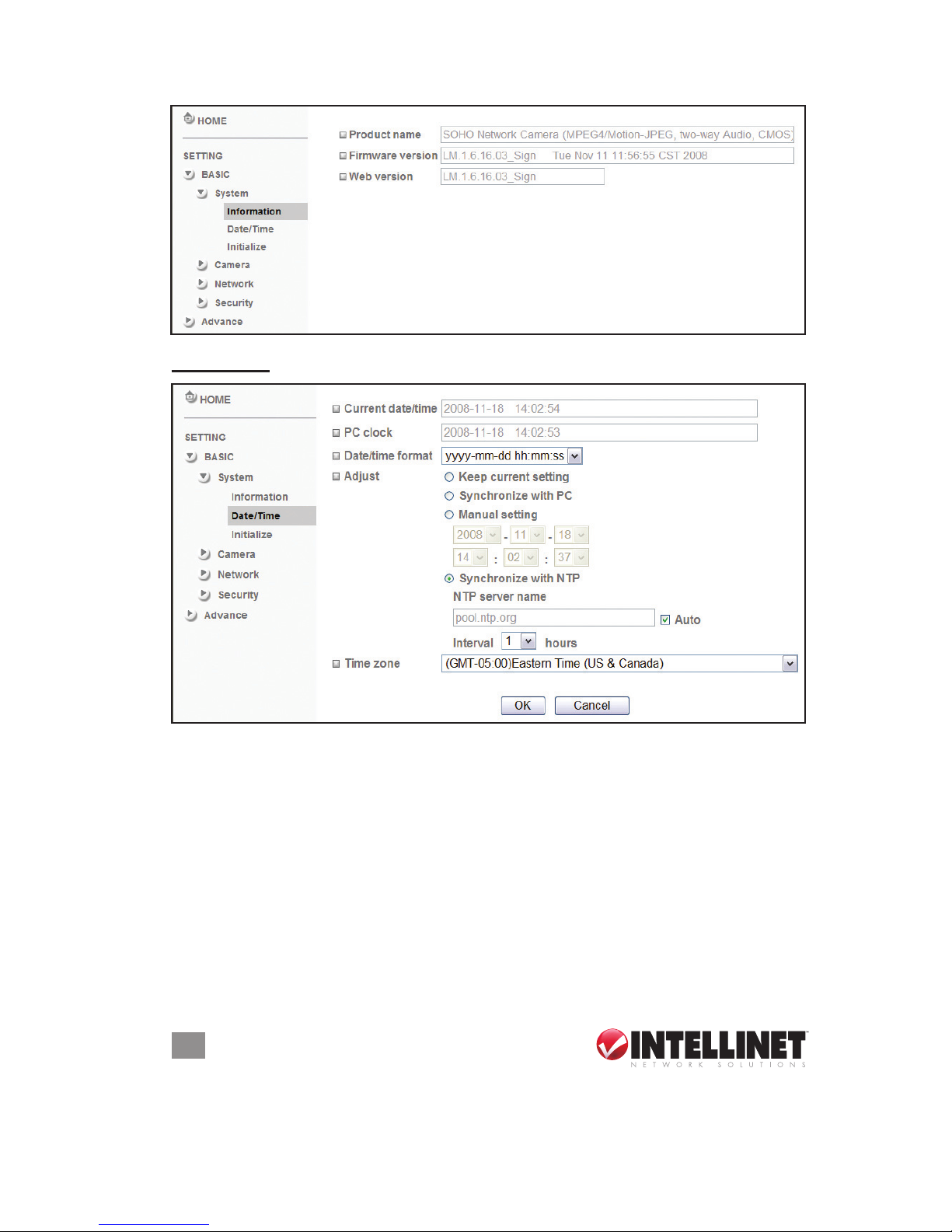
Information
The Information screen (below) displays basic product info: product
name, rmware version and Web version.
1 7 58
4
6
2
3
9
0
Page 14
14
OPERATION
Date/Time
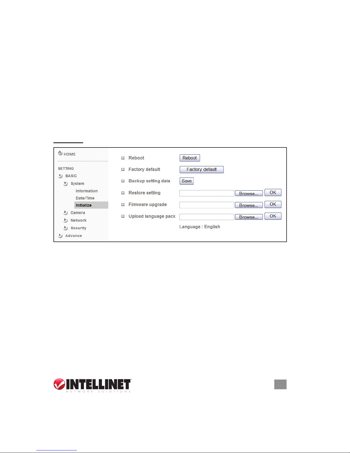
Current date/time — The current date and time of the device is displayed.
PC clock — This displays the date and time of the monitoring PC clock.
Date & time format — In the pull-down menu, select a time display
format: yyyy-mm-dd hh:mm:ss (year-month-day / hour:minute:second),
mm-dd-yyyy hh:mm:ss (month-day-year / hour:minute:second) or
dd-mm-yyyy hh:mm:ss (day-month-year / hour:minute:second).
Adjust — Select one of four time adjusting modes:
• Keep current setting: Keeps the current date and time of the device.
• Synchronize with PC: Makes the date/time of the device the same
as that of the monitoring PC.
• Manual setting: Select to manually adjust the device date and time.
Page 15
15
OPERATION
• Synchronize with NTP: Specify the NTP server name and the
Refresh Interval to synchronize the date and time of the device with
those of the time server, known as the NTP (Network Time Protocol)
server. Note: The NTP server is an Internet standard protocol
server (built on top of TCP/IP) that ensures accurate synchronization
to the millisecond of computer clock times in a network of computers.
NTP server name — Enter the host name or IP address of the NTP
server (up to 64 characters).
Time zone — From the pull-down menu, select the time zone and time
difference from Greenwich Mean Time (GMT) where the device is
installed.
Initialize
Reboot — Click to reboot the device. When the conrmation displays,
click “OK” to proceed. It takes about two minutes to reboot the device.
Factory default — Click to reset the camera to the factory default settings.
When the conrmation displays, click “OK” to proceed. The Network
LED will blink, and, after completing adjustments to the default
settings, the camera will reboot automatically. Do not turn off the
camera until the reboot is complete.
Backup setting data — To save the setting data of the device to a le,
click “Save” and follow the instructions on the browser to direct the
le to your specied location.
Restore setting — To load the saved setting data of the camera, click
“Browse” and select the le the data is stored in. Click “OK”; the
camera is adjusted according to the loaded data and is then restarted.
Page 16
16
OPERATION
Firmware update — To upgrade the device software, click “Browse” and
select the le for upgrading. When the conrmation displays, click
“OK” to start upgrading. The device will reboot upon completion.
NOTE: Use only upgrade les that are meant specically for this
device; otherwise, problems may occur. Also, do not turn off the
device or disconnect the network until the upgrade is completed.
Upload language pack — Click “Browse” and select the le for upgrading.
When the conrmation box displays, click “OK” to start upgrading.
The upgrade is applied immediately. The default language is English.
CAMERA
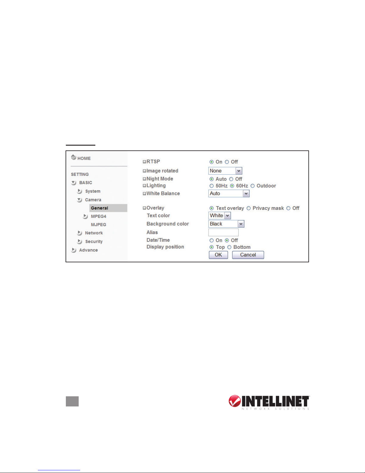
General
RTSP — Switch the RTSP streaming on/off. NOTE: RTSP (Real Time
Streaming Protocol) is supported by most the media clients (Real
Player, Media Player, QuickTime, etc.).
Image Rotate — Enables you to mirror or ip the display screen.
Night Mode — Switch the mode on (“Auto”) or off.
Lighting — Choose the lighting environment: “50Hz,” “60Hz” or “Outdoor.”
White Balance — Select from the drop-down menu: “Auto,” “Fluorescent,”
“Incandescent” or “Black & White.”
Overlay — Select “Text Overlay” so users can see some information on
the display screen, such as Date/Time and user-dened text; select
“Privacy Mask” so users can conceal an area of the video image.
• Text color: Select your preference from the pull-down menu.
• Background color: Select your preference from the pull-down menu.
Page 17
17
OPERATION
• Alias: Enter a name for the camera in this eld.
• Date/Time: Turn this display on or off to suit your preference.
• Display position: Select where you want the date/time to appear.
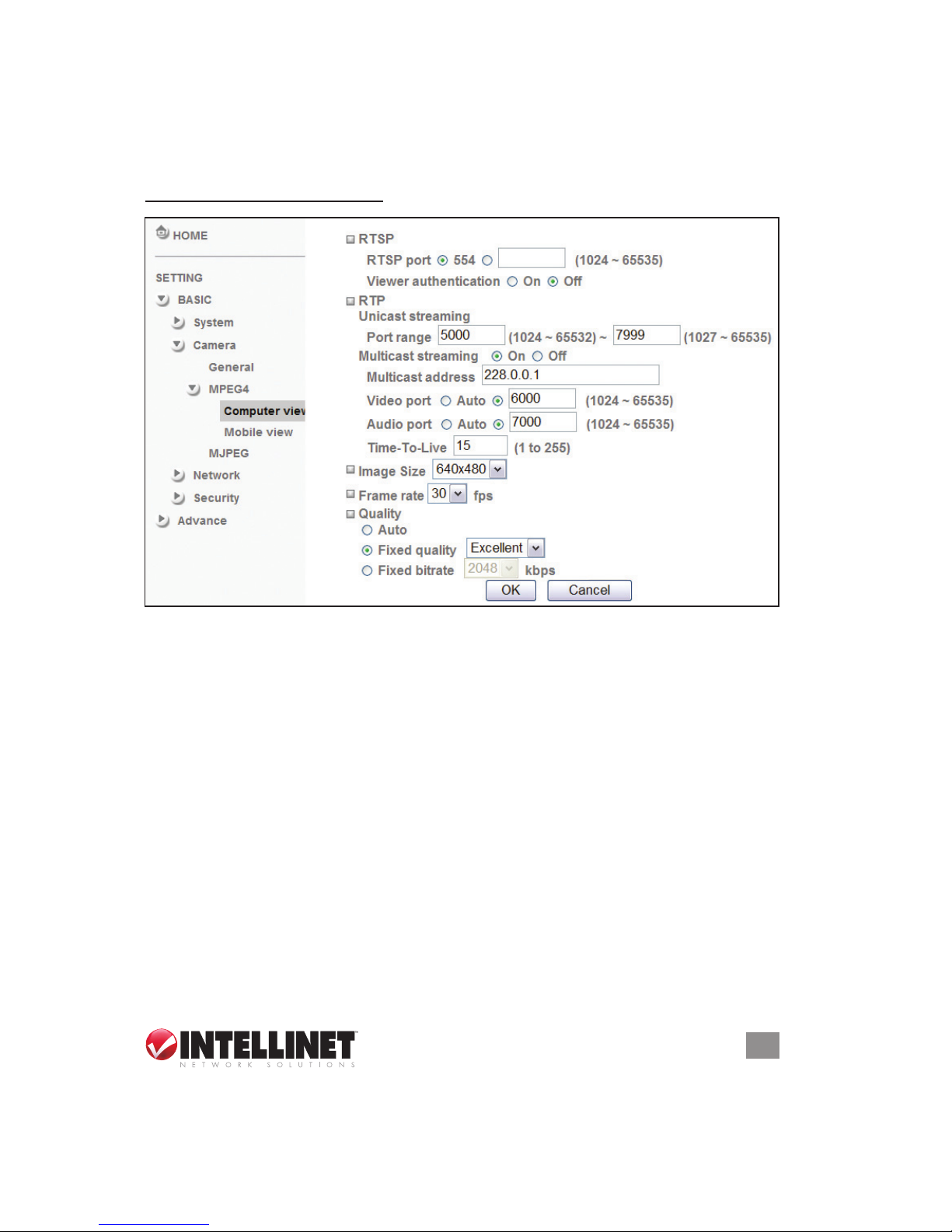
MPEG4 / Computer View
RTSP — This set of options (shown above) is available if RTSP mode
is enabled (on the Camera / General screen).
• RTSP port: Specify the transmission port number of RTSP streaming
video. The default value is 554.
• Viewer authentication: When enabled (“On”), users viewing through
RTSP will be prompted to enter a username and password.
RTP — This set of options is available if RTSP mode is enabled (on the
Camera / General screen).
• Unicast streaming: Specify the transmission port range of RTP
streaming video. RTP will select a port randomly from the range.
• Multicast streaming: Specify the multicast server address and the
transmission port numbers of the audio and the video data (even
numbers from 1024 to 65534).
• Time-To-Live: Set the maximum TTL that multicast can pass through.
MPEG4 viewer port — This set of options is available if RTSP mode is
disabled (on the Camera / General screen).
Page 18
18
OPERATION
• Unicast streaming / Video/Audio Port Number: Specify the
transmission port number (any even number from 1024 to 65534)
of the video data, which is initially set to 8090. If you change the
setting of Video/Audio Port Number, the setting of Video/Audio Port
Number (SSL) will change automatically.
Image Size — Using the drop-down menu options, specify the image
size the network camera transmits: 640 x 480, 320 x 240 or 160 x 120.
Frame rate — Using the drop-down menu, set the frame rate of the
MPEG4 image: 5, 10, 15, 20, 25 or 30 fps (frames sent per second).
Quality — You have three options for determining the image quality:
• Auto: The quality and bitrate will be automatically decided according
to the frame rate.
• Fixed Quality: The drop-down menu offers “Medium,” “Standard,”
“Good,” “Detailed (Delicate)” and “Excellent.”
• Fixed Bitrate: Set the bit rate of MPEG4 image transmission for a line:
64, 128, 256, 384, 512, 768, 1024, 1280, 1536 or 2048 kbps.
NOTE: The selected frame rate and bit rate are tentative values. The
actual frame rate and bit rate may be different depending on the image
size, the shooting scene or the network conditions.
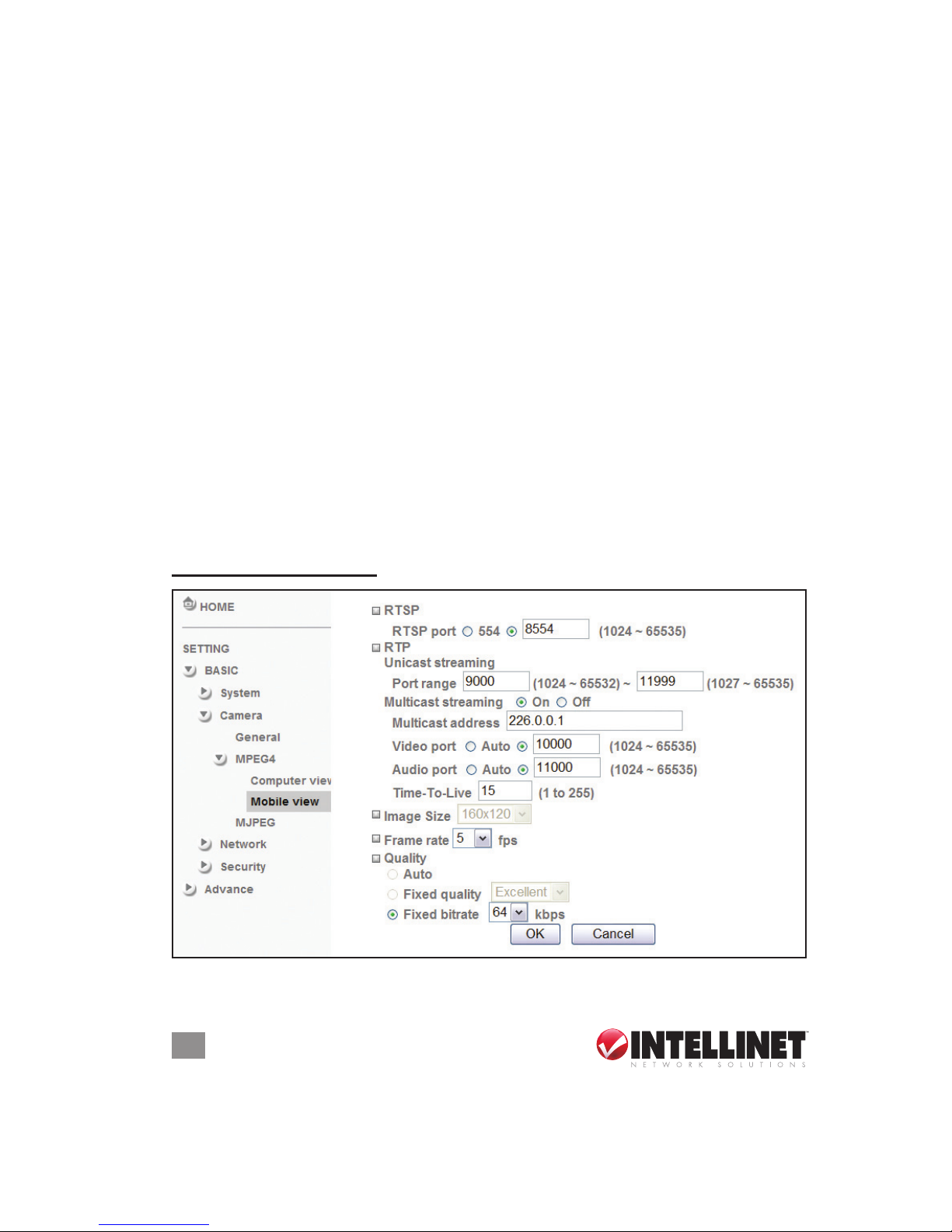
MPEG4 / Mobile View
RTSP — This set of options (shown above) is available if RTSP mode
Page 19
19
OPERATION
is enabled (on the Camera / General screen).
RTP — This set of options is available if RTSP mode is enabled (on the
Camera / General screen).
• Unicast streaming: Specify the transmission port range of RTP
streaming video. RTP will select a port randomly from the range.
• Multicast streaming: Specify the multicast server address and the
transmission port numbers of the audio and the video data. They’re
initially set to 10000 and 11000. Specify an even number from 1024
to 65534.
• Time-To-Live: Set the maximum TTL that multicast can pass through.
Image Size — For Mobile View, the size is xed at 160 x 120.
Frame rate — Using the drop-down menu, set the frame rate of the
MPEG4 image: 5, 10, 15 or 20 fps (frames sent per second).
Quality — You have three options for determining the image quality:
• Auto: The quality and bitrate will be automatically decided according
to the frame rate.
• Fixed Quality: The drop-down menu offers “Medium,” “Standard,”
“Good,” “Detailed” and “Excellent.”
• Fixed Bitrate: Set the bit rate of MPEG4 image transmission for a line:
16, 32 or 64 kbps.
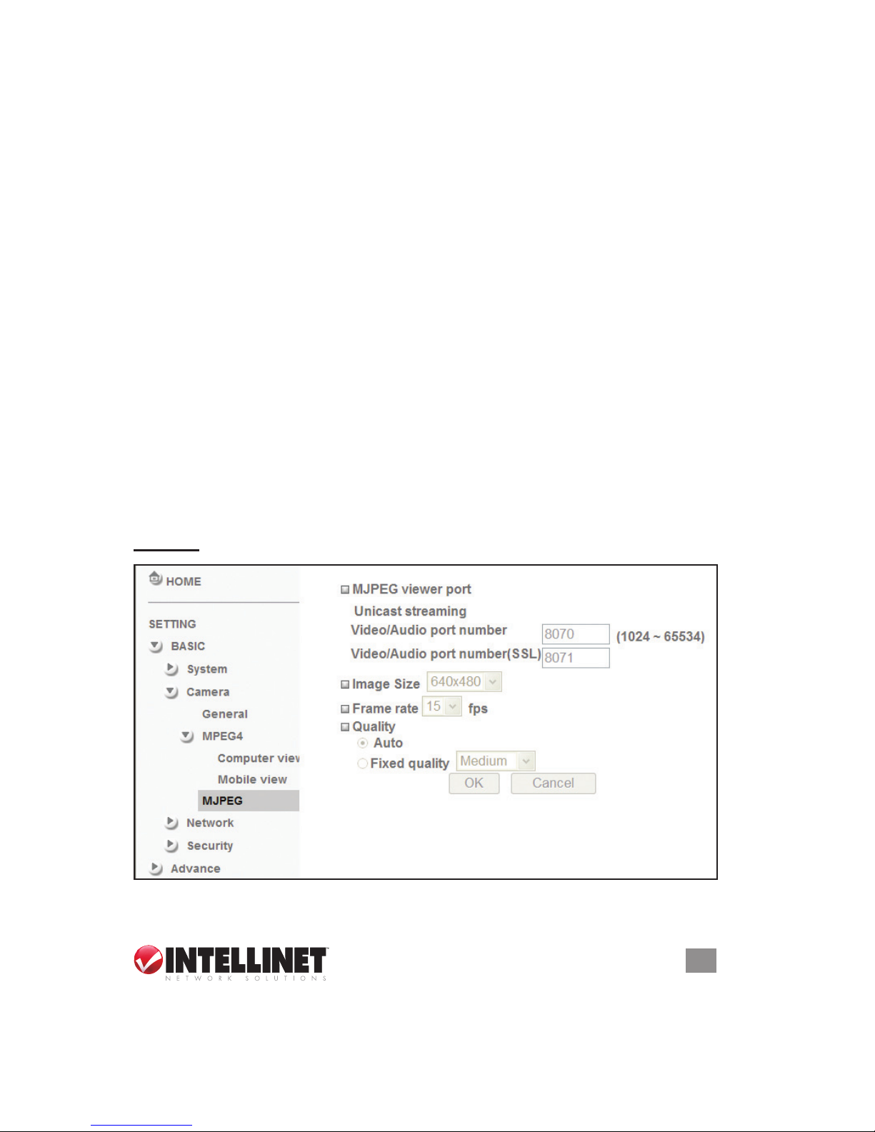
MJPEG
MJPEG viewer port — These options (shown above and similarly for
Page 20
20
OPERATION
Image Size, Frame rate and Quality) are unavailable if the RTSP
mode is enabled (which means the MJPEG streaming is closed).
• Unicast streaming: Specify the
transmission port number (any even number from 1024 to 65534)
of the video data, which is initially set to 8070. If you change the
setting of Video/Audio Port Number, the setting of Video/Audio Port
Number (SSL) will change automatically.
Image Size — Using the drop-down menu options, specify the image
size the network camera transmits: 640 x 480, 320 x 240 or 160 x 120.
Frame rate — Using the drop-down menu, set the frame rate of the
MJPEG image: 5, 10 or 15 fps (frames sent per second).
Quality — You have two options for determining the image quality:
• Auto: The quality will be automatically decided.
• Fixed quality: The drop-down menu offers “Medium,” “Standard,”
“Good,” “Detailed (Delicate)” and “Excellent.”
NETWORK
Information
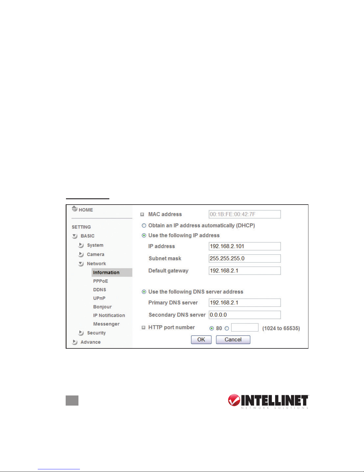
MAC address — Displays the MAC address of the device.
Obtain an IP address automatically (DHCP) — Select only if a DHCP
server is installed and working on the network.
Page 21
21
OPERATION
Use the following IP address — Select when a xed IP address is set.
• IP address: Enter the IP address of the device.
• Subnet mask: Enter the subnet mask.
• Default gateway: Enter the default gateway.
Use the following DNS server address — Select when setting the xed
address as the IP address of DNS server.
• Primary DNS server: Enter the IP address of the primary DNS server.
• Secondary DNS serve: Enter the IP address of the secondary
DNS server, if necessary.
HTTP port number — Select “80,” in general situations. If you want to
use a port number other than 80, select the text eld and enter a port
number between 1024 and 65535. NOTE: When setiing the HTTP
port number to a number other than 80 on the Network screen or in
the setup program, access the device by entering the IP address of
the device on the Web browser as in this example with the HTTP
port number set to 2000: http://192.168.1.100:2000/.
NOTE: The camera needs to be rebooted after it nishes changing the
network settings completely. Also, if you connect the camera directly to
a computer, the default network domain of the camera is 192.168.1.xx.
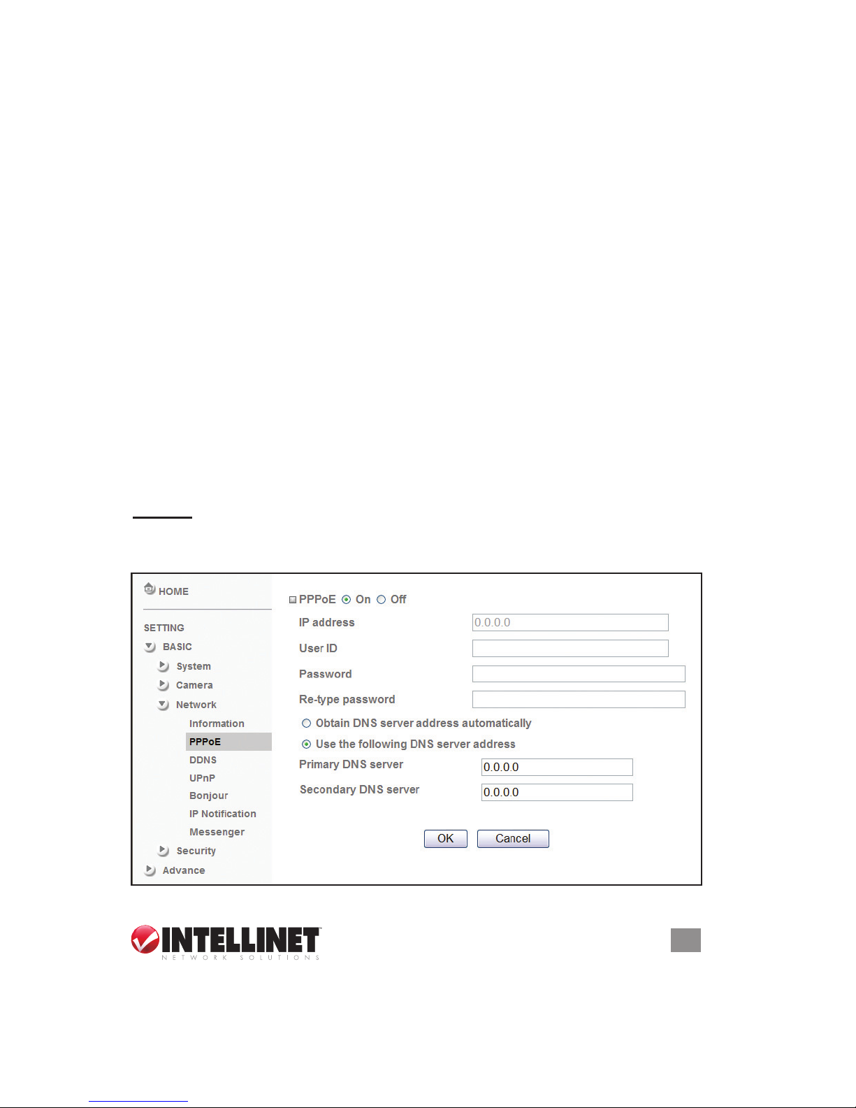
PPPoE
Congure this screen when you connect the device using Point-to-Point
Protocol over Ethernet. PPPoE is the protocol widely used in xDSL
Page 22
22
OPERATION
(digital afliate lines such as ADSL, VDSL or SDSL) as the authentication
and connection system. When you use the PPPoE function, you need
to turn on the DDNS or IP Notication function at same time.
IP address — Displays the IP address obtained at the PPPoE connecting
with the network.
User ID — Enter the user ID for authentication necessary for PPPoE
connections (up to 64 characters).
Password — Enter the password for authentication necessary for PPPoE
connections (up to 32 characters).
Re-type password — Re-type the password to conrm.
Obtain DNS server address automatically — Select to obtain the address
of the DNS server automatically.
Use the following DNS server address — Select when setting the xed
address as the IP address of DNS server.
Primary DNS server — Enter the IP address of the primary DNS server.
Secondary DNS server — Enter the IP address of the secondary DNS
server.
NOTE: The camera needs to be rebooted after it nishes changing the
network settings completely.
DDNS
DDNS is a system that allows the domain name data held in a name
server to be updated in real time. The most common use for DDNS is
allowing an Internet domain name to be assigned to a computer with a
varying/dynamic IP address, making it possible for other sites on the
Internet to establish a connection to the machine without needing to
track the IP address themselves.
Page 23
23
OPERATION
To use the DDNS function, you rst need to register and create an account on the DDNS server.
1. Log on to http://www.dyndns.org and click “Create Account.”
2. Follow the step-by-step instructions on the DynDNS screens, inputting
all information requested.
3. Log in with the new account and go to Account → My Hosts → Add
Host Services.
4. Enter the domain in the Hostname eld and select a sub-domain
from the drop-down menu.
5. After entering the information, check your DDNS service.
6. On the camera’s DDNS screen, ll in the elds and reboot the camera.
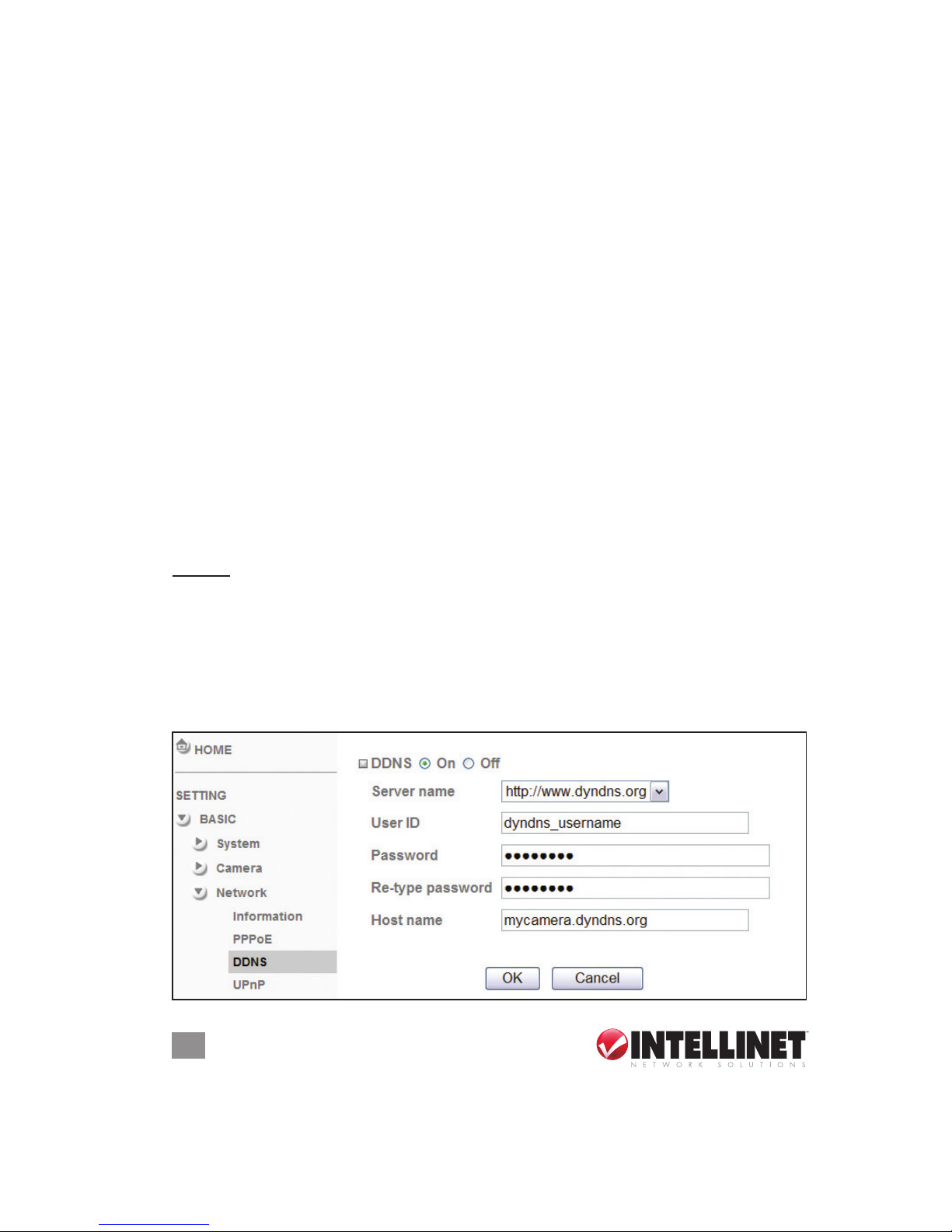
Server name — Choose the DDNS server from the list.
User ID — Enter the user ID for authentication necessary for DDNS
connections (up to 64 characters).
Password — Enter the password for authentication necessary for DDNS
connections (up to 32 characters).
Re-type password — Re-type the password to conrm.
Host name — Enter the host name registered to the DDNS server.
UPnP
The device includes support for UPnP (Universal Plug and Play), which
Page 24
24
OPERATION
is enabled by default. If UPnP is also enabled on your computer, the
device will automatically be detected and a new icon will be added to
your My Network Places folder. It provides port forwarding for opening
a port in a router or rewall in a private network in order to let a party
from the outside world contact a user inside. NOTE: If you’re using a
router to access the Internet and the router supports the UPnP IGD
function, you need to enable the UPnP Port Forwarding function.
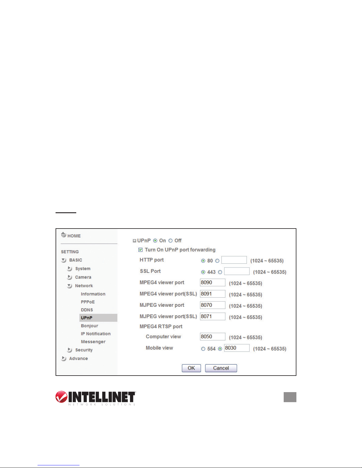
HTTP port — If you want to use a port number other than 80 (the
default setting), select the text eld and enter a port number between
1024 and 65535.
SSL port — If you want to use a port number other than 443 (the default
setting), select the text eld and enter a port number between 1024
and 65535.
MPEG4 viewer port — Use the default port number (8090) or enter a
different port number between 1024 and 65535.
MPEG4 viewer port (SSL) — Use the default port number (8091) or
enter a different port number between 1024 and 65535.
MJPEG viewer port — Use the default port number (8070) or enter a
different port number between 1024 and 65535.
MJPEG viewer port (SSL) — Use the default port number (8071) or
enter a different port number between 1024 and 65535.
MPEG4 RTSP port — Use the default port number (8050 for computer
view; 8030 for mobile view) or enter a different port numbers between
1024 and 65535.
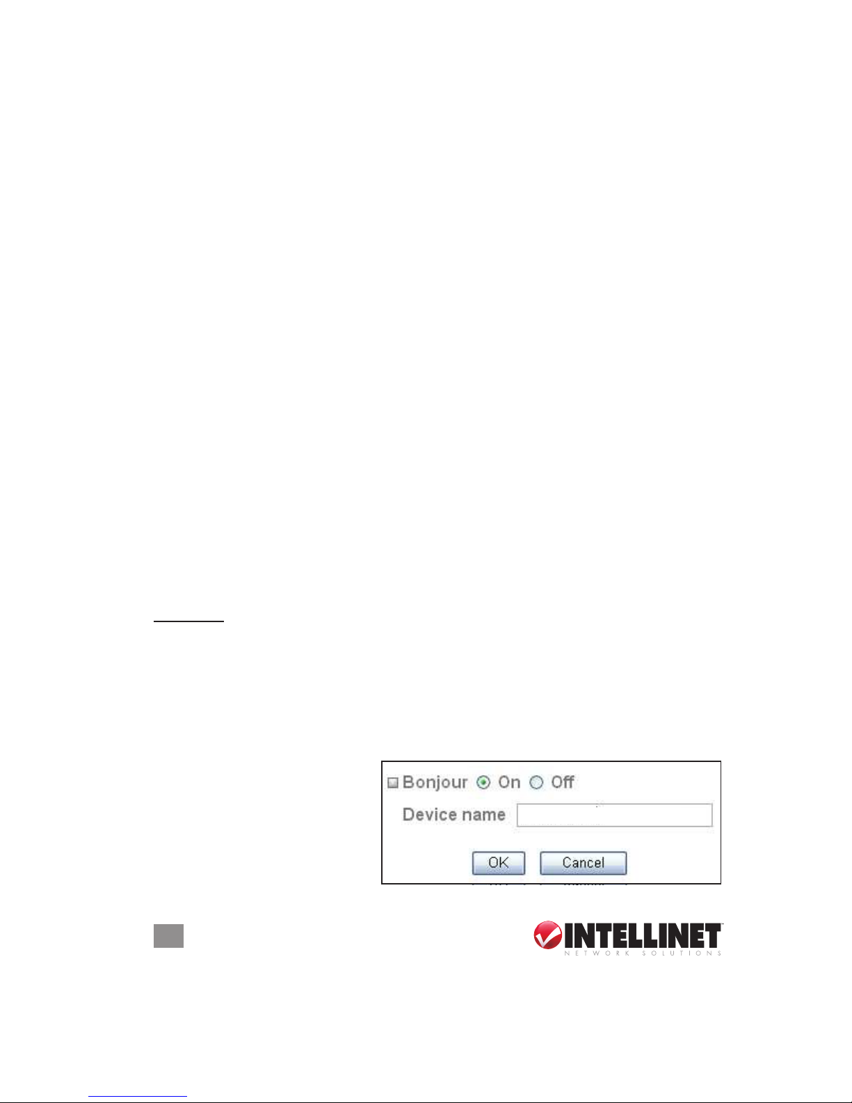
Bonjour
Bonjour, also known as zero-conguration networking, uses industry-
standard IP protocols to allow computers, devices and services on IP
networks to nd each other without the need to enter IP addresses or
congure DNS servers.
To use Bonjour in your Windows browser UI, follow the instructions at
http://www.apple.com/support/downloads/bonjourforwindows.html.
Bonjour — Select “On” to
enable the function.
Device name — Enter a
name you’ll recognize.
My camera
Page 25
25
OPERATION
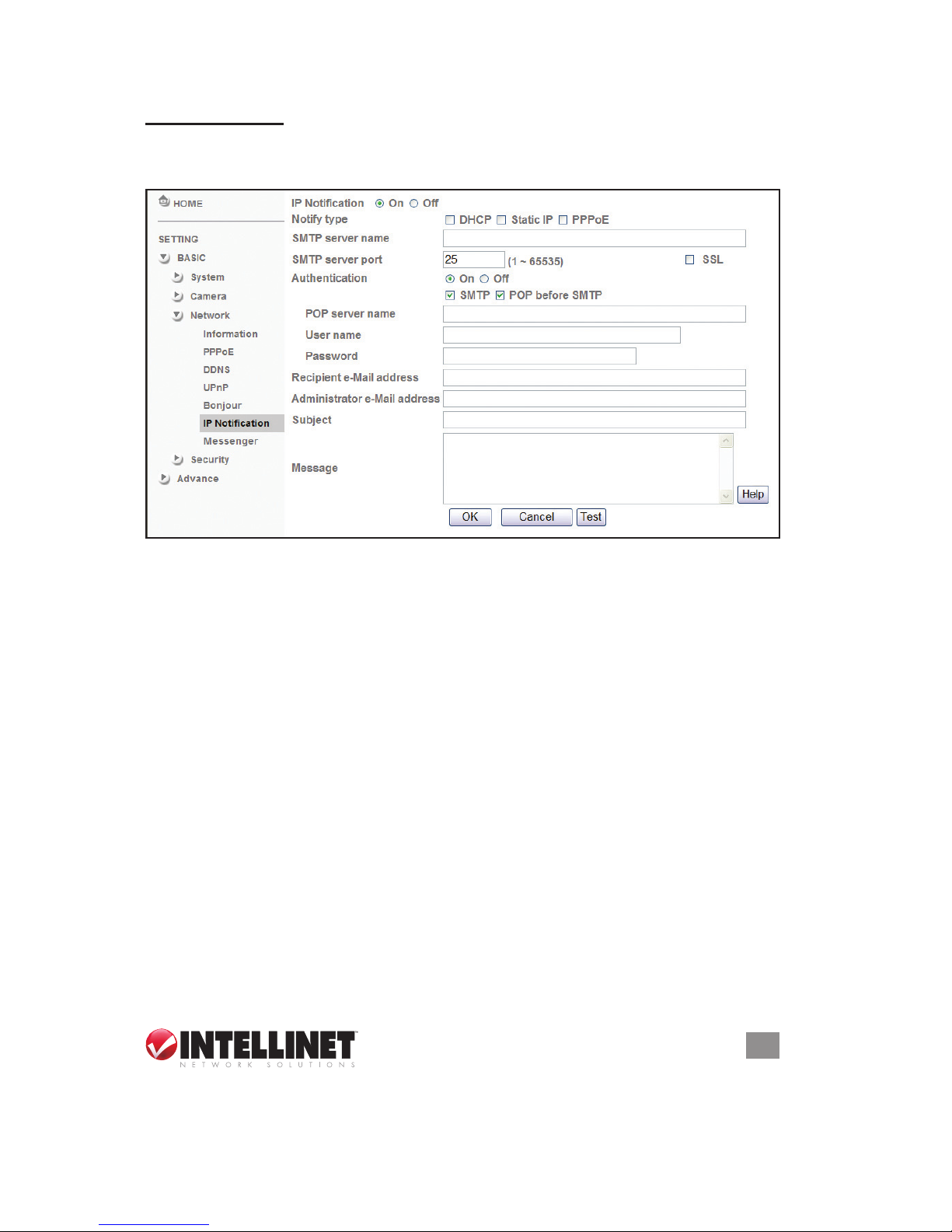
IP Notication
When IP Notication is enabled (“On”), you can send an e-mail
notication of the completion of the network setting.
Notify type — Select one of the options listed.
SMTP server name — Enter the SMTP server name (to 64 characters)
or the IP address of the SMTP server.
SMTP Server Port — You can set port number from 1 to 65535 according
to your mail server. The default value is 25.
• SSL: Select if the mail server you use has security restrictions. NOTE:
If you use g-mail as your mail server, use 587 as the port number.
Authentication — Select the authentication you want to be required when
you send an e-mail. By selecting “Off,” no authentication is necessary
when an e-mail is sent; by selecting “On,” one or both of the following
authentication methods — SMTP or POP before SMTP — need to
be assigned.
• SMTP: Select if SMTP authentication is required to send an e-mail.
• POP before SMTP: Select if POP-before-SMTP authentication is
necessary when an e-mail is sent.
• POP server name: This needs to be provided when “POP before
SMTP” is selected in “Authentication.” Enter the POP (receiving
mail) server name (up to 64 characters), or enter the IP address of
the POP server. This is needed when the SMTP server that sends
Page 26
26
OPERATION
e-mails performs authentication using the POP user account.
• User name, Password: Enter the username and password of the
user who has the mail account. This is needed when the SMTP
server that sends e-mails performs authentication.
Recipient e-mail address — Enter the recipient e-mail address (up to
64 characters). You can specify as many as three recipient e-mail
addresses.
Administrator e-mail address — Enter the administrator e-mail address
(up to 64 characters). This address is used for reply mail and for
sending system messages from the SMTP server.
Subject — Enter the subject/title of the e-mail (up to 64 characters). With
respect to mail which is sent according to the IP notication.
Message — Enter the text of the e-mail (up to 384 characters). Default
values provide network information such as IP address, port number,
MAC address, model, rmware version and Web version.
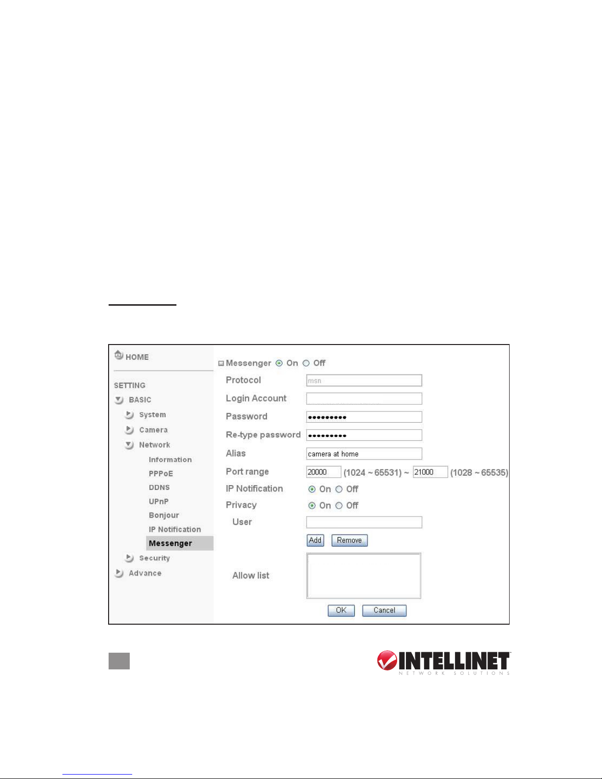
Messenger
This is an easy-connect feature to see the camera’s private and public
IP addresses.
bucs_fan@hotmail.com
bigger_bucs_fan@hotmail.com
Page 27
27
OPERATION
Protocol — Only MSN is supported.
Login Account — The camera will use this account to log in to the MSN
server. (You can establish an account at http://www.msn.com).
Password — Enter the password for authentication.
Re-type password — Re-type the password to conrm.
Alias — This alias will display on MSN as it appears here.
Port range — The camera will select one port from this range for video
transmission.
IP Notication — Enable or disable. When “On,” the camera will send
IP notications to the users who are allowed.
Privacy — Enable or disable. When “On,” only users on the allow list
can access the camera.
User — Enter a username for placement on the allow list.
Allow list — When “Privacy” is enabled, only users on the allow list can
access the camera.
SECURITY
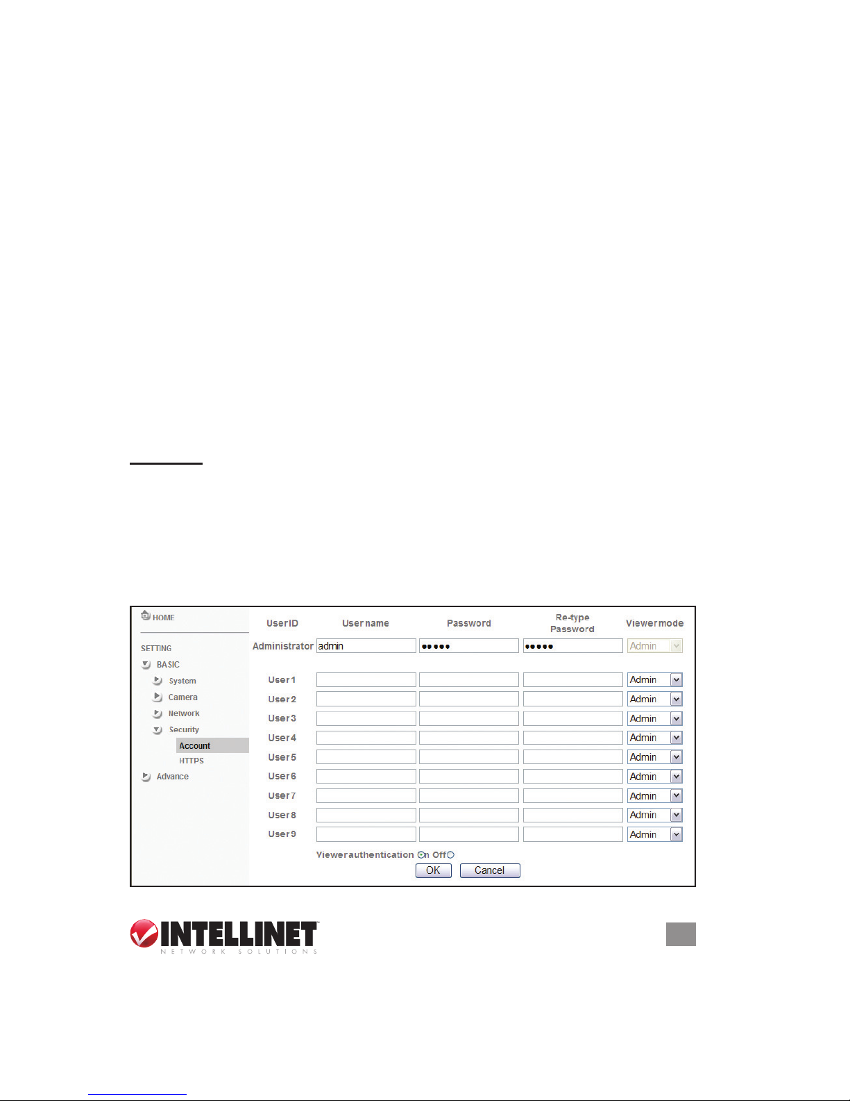
Account
The camera’s default account/username and password settings are both
“admin.” This means that anyone can access the camera — including
its conguration — if the IP address is known. Thus, it’s necessary that
a password be assigned if the camera is meant to be accessed by others.
Use this menu to set the usernames, passwords and access rights for
the administrator and as many as nine different users (User 1 to User 9).
Page 28
28
OPERATION
User name — Enter a username between 4 and 16 characters.
Password — Enter a password between 4 and 16 characters.
Re-type password — Re-enter the password to conrm.
Viewer Mode — From the drop-down menu, select a level of access.
• Admin: Access to the entire camera conguration.
• Operator: Access to the Live View.
• Viewer: Can only view the Live View.
Viewer authentication — Allows any viewer direct access to Live View.
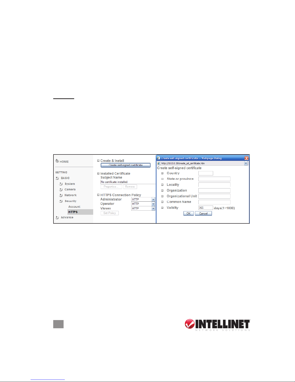
HTTPS
HTTPS is a URI (uniform resource identier) scheme used to indicate
a secure HTTP connection. It is syntactically identical to the http://
scheme normally used for accessing resources using HTTP. Using an
https: URL indicates that HTTP is to be used, but with a different
default TCP port (443) and an additional encryption/authentication layer
between the HTTP and TCP. You can use the IP camera through HTTPS
by using https:// instead of http://.
Create & Install — Create a self-signed certicate for HTTPS to recognize.
Installed Certicate — Display or remove the properties of the installed
certicate.
HTTPS Connection Policy — Using the drop-down menus, select the
HTTPS connection policy for each level of user.
NOTE: When enabling HTTPS with RTSP mode on, the camera only
protects setting such as username and password (and not video or
audio). When enabling HTTPS with RTSP mode off, the camera will
protect all settings, including video and audio.
Page 29
29
OPERATION
Advanced
FTP CLIENT
Congure these settings to capture and send images triggered by the
built-in motion detection function to an FTP server.
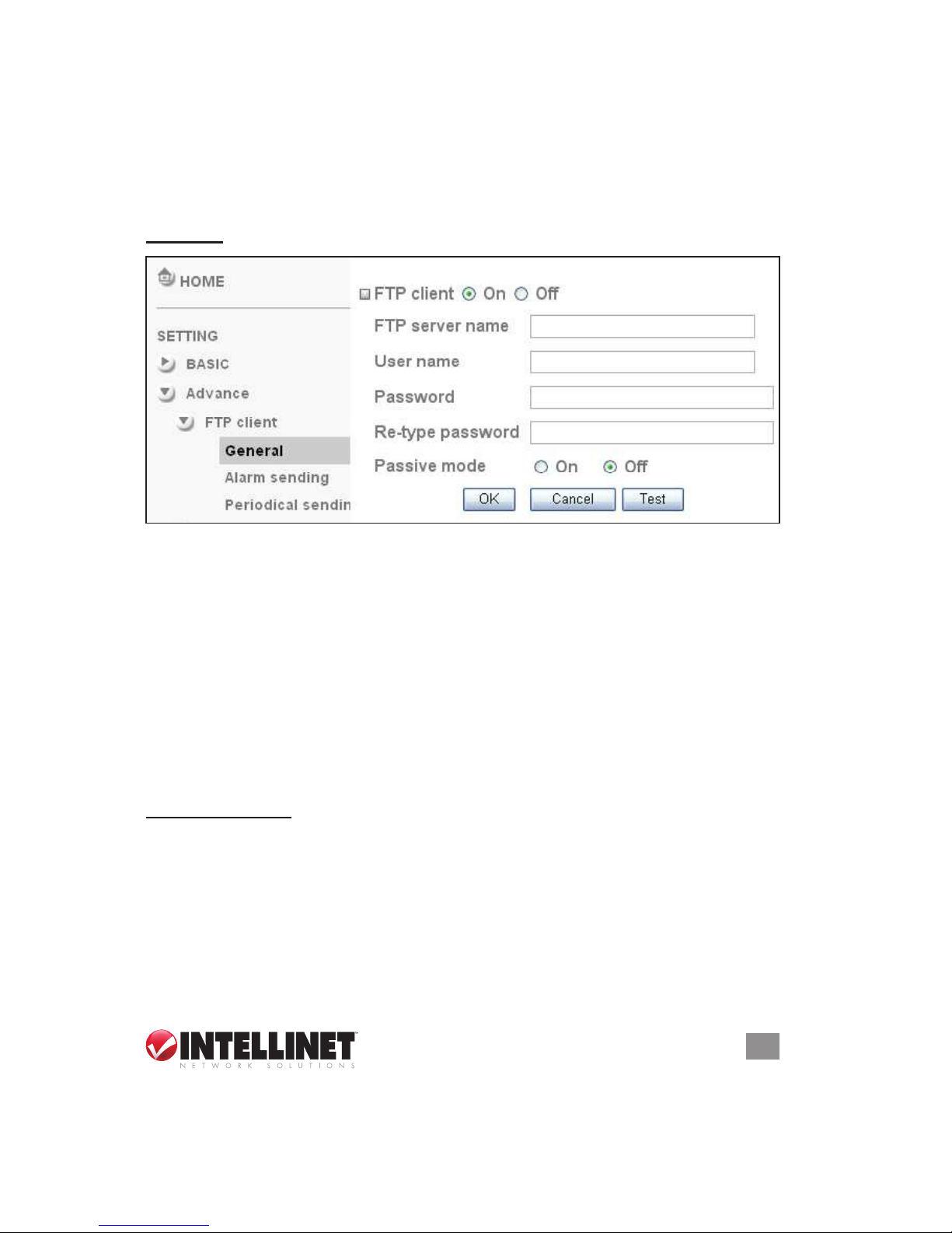
General
FTP client function — Select “On” to enable and display the Client Setting
screen. NOTE: Frame rate and operability on the main viewer may
decrease while a le is being transmitted by the FTP client function.
FTP server name — Enter the FTP server name IP address (up to 64
characters) to upload still images.
User name — Enter the username for the FTP server.
Password — Enter the password for the FTP server.
Re-type password — To conrm the password, enter the same
characters entered in the Password eld.
Passive mode — Select “On” to connect to the FTP server using the
passive mode.
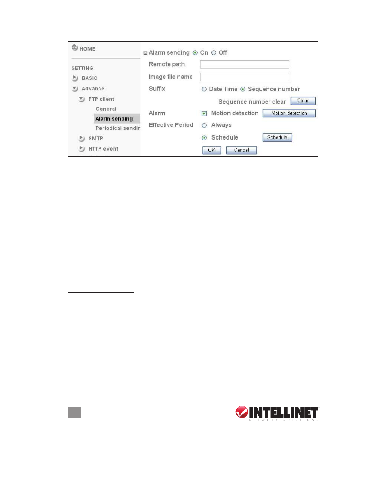
Alarm Sending
Set “Alarm sending” to “On” and use this screen’s options to forward
images and associated audio les — linked with the external sensor
input or with the built-in motion detection function — to an FTP server.
Remote path — Enter the path to the destination on the FTP server (up
to 64 characters).
Image le name — Enter the le name you want to assign to the images
when sending to the FTP server (up to 10 alphanumeric characters).
Page 30
30
OPERATION
Sufx — Select a sufx to add to the le name:
• Date Time: Seven pairs of digits (14 total) represent the year, month,
day, hour, minute, second and consecutive number.
• Sequence number: Select to append a consecutive-number sequence
of 10 digits (between 0000000001 and 4294967295) and two xed
digits to the image le name. Click “Clear” to return the number to 1.
Alarm — Select to use the Motion Detection function as a sensor (and
display the motion detection function screen — see the Motion
Detection section below).
Effective period — Select the period for which the periodic sending is
in effect: “Always” or “Schedule.” To specify the period, select/click
“Schedule” and the setting menu is displayed (see the Schedule
section below).
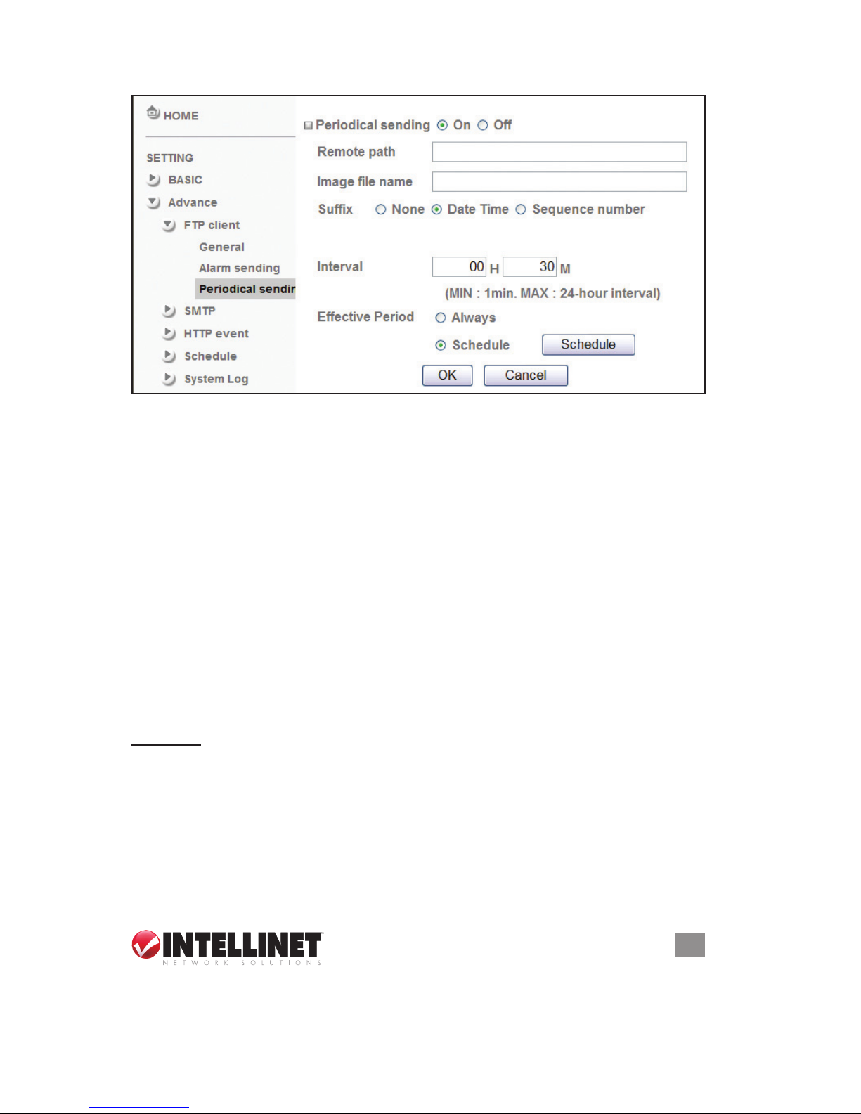
Periodic Sending
By enabling this function (“On”), you establish the settings so that an
image le is periodically sent to the FTP server.
Remote path — Enter the path to the destination on the FTP server (up
to 64 characters).
Image le name — Enter the le name you want to assign to the images
when sending to the FTP server (up to 10 alphanumeric characters,
including hyphen and underscore).
Sufx — Select a sufx to add to the le name:
• None: The name of the sent le will be the image le name.
• Date Time: Seven pairs of digits (14 total) represent the year, month,
Page 31
31
OPERATION
day, hour, minute, second and consecutive number.
• Sequence number: Select to append a consecutive-number sequence
of 10 digits (between 0000000001 and 4294967295) and two xed
digits to the image le name. Click “Clear” to return the number to 1.
Interval — You can determine the interval between sent les, with a
minimum setting of 1 minute and a maximum of 24 hours.
Effective period — Select the period for which the periodic sending is
in effect: “Always” or “Schedule.” To specify the period, select/click
“Schedule” and the setting menu is displayed (see the Schedule
section below).
SMTP
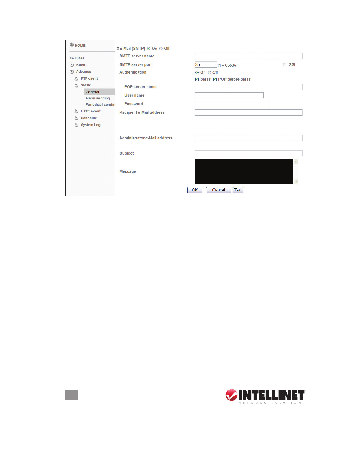
The settings on this screen are for sending an e-mail with an image
attached that’s been triggered by the built-in motion detection function.
The image le can also be sent periodically.
General
Enable this function by selecting “On.” To disable, select “Off” and
click “OK.” NOTE: During image-le e-mail transmissions, frame rate
and operational performance of the monitor image of the main viewer
may decline. Also, while the camera video mode is set to MPEG4, the
image of the composite video signal output from the video output
connector of the camera may be distorted.
Page 32
32
OPERATION
SMTP server name — Enter the SMTP server name (up to 64 characters)
or IP address.
SMTP Server Port — You can set port number from 1 to 65535 according
to your mail server. The default value is 25.
• SSL: Select if the mail server you use has security restrictions. NOTE:
If you use g-mail as your mail server, use 587 as the port number.
Authentication — Select the authentication you want to be required when
you send an e-mail. By selecting “Off,” no authentication is necessary
when an e-mail is sent; by selecting “On,” one or both of the following
methods — SMTP or POP before SMTP — need to be assigned.
• SMTP: Select if SMTP authentication is required to send an e-mail.
• POP before SMTP: Select if POP-before-SMTP authentication is
necessary when an e-mail is sent.
• POP server name: This needs to be provided when “POP before
SMTP” is selected in “Authentication.” Enter the POP (receiving
mail) server name (up to 64 characters), or enter the IP address of
the POP server. This is needed when the SMTP server that sends
e-mails performs authentication using the POP user account.
• User name, Password — Enter the username and password of the
user who has the mail account. This is needed when the SMTP
Page 33
33
OPERATION
server that sends e-mails performs authentication.
Recipient e-mail address — Enter as many as three recipient e-mail
addresses (up to 64 characters each).
Administrator e-mail address — Enter the administrator e-mail address
(up to 64 characters). This address is used for reply mail and for
sending system messages from the SMTP server.
Subject — Enter the subject/title of the e-mail (up to 64 characters). With
respect to mail which is sent according to the IP notication.
Message — Enter the text of the e-mail (up to 384 characters). A line
break is equivalent to two characters.
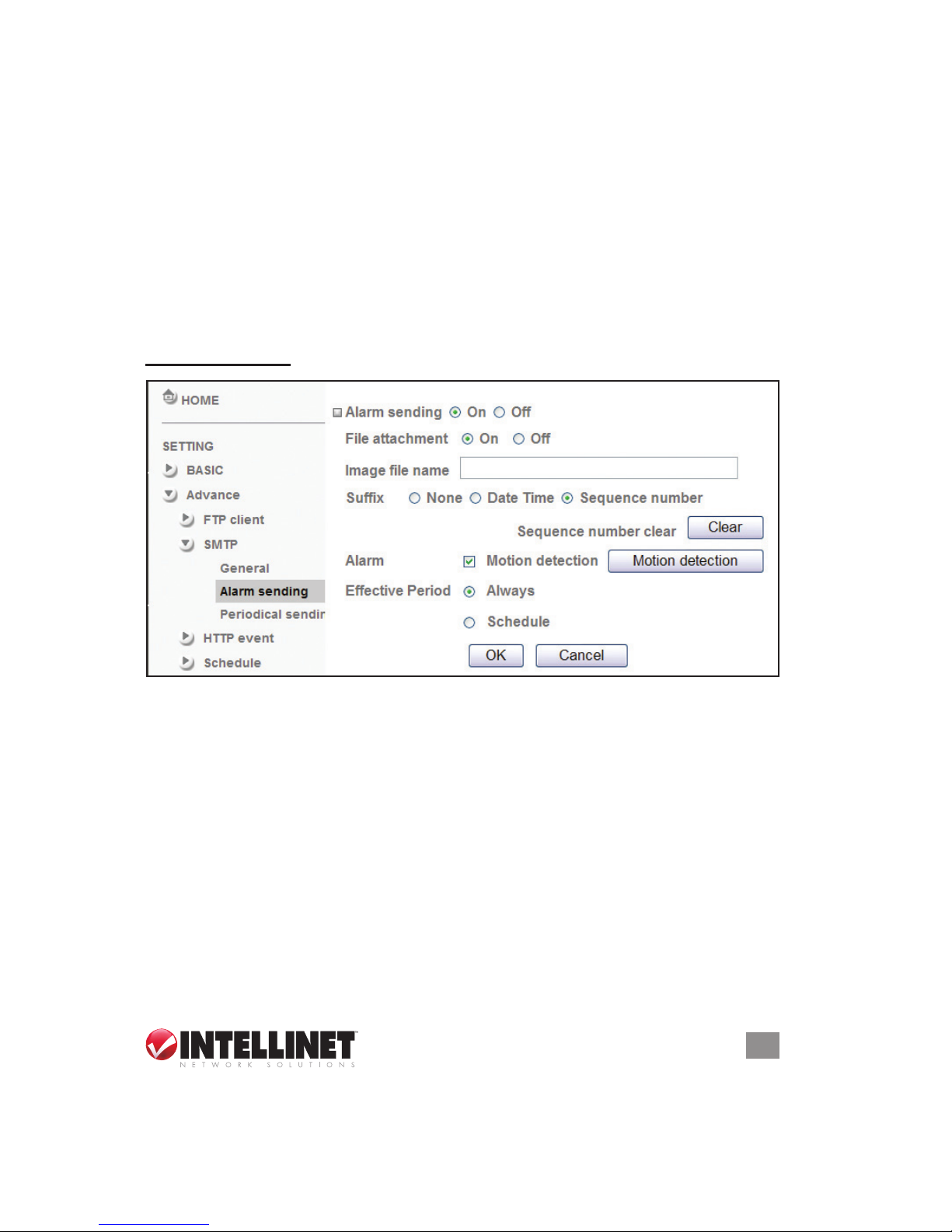
Alarm Sending
Alarm sending — Select “On” to send e-mail with a connection to the
alarm detection by the external sensor input or by the built-in motion
detection function.
File attachment — Select “On” and the image le is attached to the e-mail
using the settings below; “Off” allows only the message to be sent.
Image le name — Enter the le name you want to assign to the images
when sending to the FTP server (up to 10 alphanumeric characters,
including hyphen and underscore.
Sufx — Select a sufx to add to the le name:
• None: The name of the sent le will be the image le name.
• Date Time: Seven pairs of digits (14 total) represent the year, month,
day, hour, minute, second and consecutive number.
• Sequence number: Select to append a consecutive-number sequence
Page 34
34
OPERATION
of 10 digits (between 0000000001 and 4294967295) and two xed
digits to the image le name. Click “Clear” to return the number to 1.
Alarm — Select to use the Motion Detection function as a sensor (and
display the motion detection function screen — see the Motion
Detection section below).
Effective period — Select the period for which the alarm sending is
in effect: “Always” or “Schedule.” To specify the period, select/click
“Schedule” (see the Schedule section below).
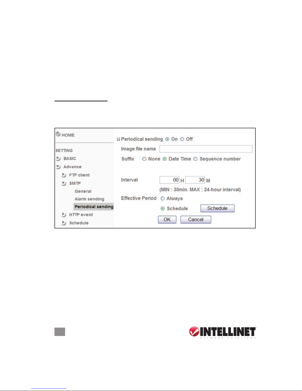
Periodic Sending
By enabling this function (“On”), you establish the settings (very similar
to those on the FTP Client screen) so that an image le is periodically
sent to the FTP server.
Image le name — Enter the le name of the image sent by SMTP (up
to 10 alphanumeric characters, including hyphen and underscore).
Sufx — Select a sufx to add to the le name:
• None: The name of the sent le will be the image le name.
• Date Time: Seven pairs of digits (14 total) represent the year, month,
day, hour, minute, second and consecutive number.
• Sequence number: Select to append a consecutive-number sequence
of 10 digits (between 0000000001 and 4294967295) and two xed
digits to the image le name. Click “Clear” to return the number to 1.
Interval — You can determine the interval between sent les, with a
minimum setting of 1 minute and a maximum of 24 hours.
Page 35
35
OPERATION
Effective period — Select the period for which the periodic sending is
in effect: “Always” or “Schedule.” To specify the period, select/click
“Schedule” (see the Schedule section below).
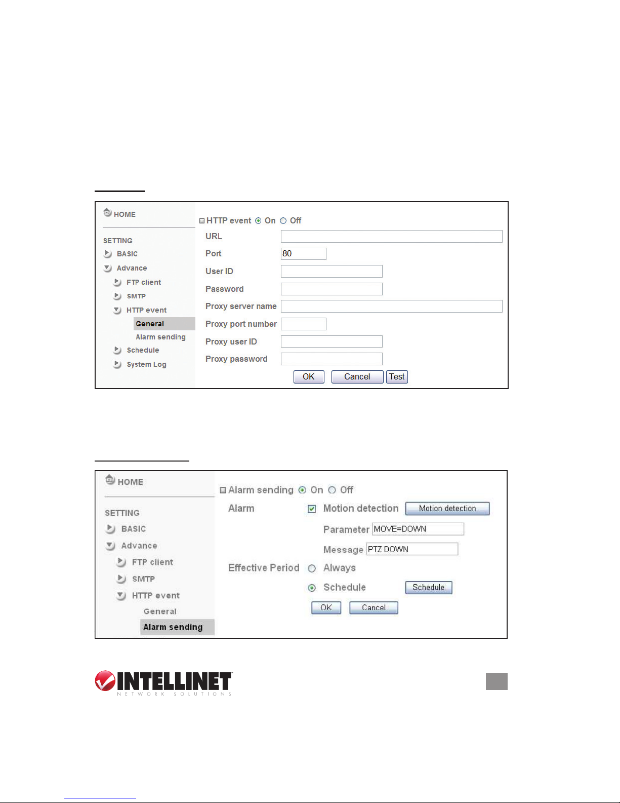
HTTP EVENT
Congure to capture and send images — linked with the external sensor
input or with the built-in motion detection function — to an HTTP server.
General
HTTP event — Enable this function (“On”) to congure the HTTP server
URL, Port, User ID, Password and Proxy Server settings. Sample
URL: 192.168.1.7/cgi-bin/operator/ptzset (should be the same as CGI).
Alarm Sending
Alarm sending — Select “On” to send e-mail with a connection to the
Page 36
36
OPERATION
alarm detection by the external sensor input or by the built-in motion
detection function.
Alarm — Select to use the Motion Detection function as a sensor (and
display the motion detection function screen). NOTE: This works only
when the Video mode is set to “MPEG4.”
Parameter — The parameter of CGI (dened in URL of HTTP → General)
is from your target device. For example, “move=down.”
Message — This will display in the form of “PTZ down.” If your target
device didn’t support the parameter of the message, you can’t see
the message. (You can just accept the message as a note.)
Effective period — Select the period for which the periodic sending is
in effect: “Always” or “Schedule.” To specify the period, select/click
“Schedule” (see the Schedule section below).
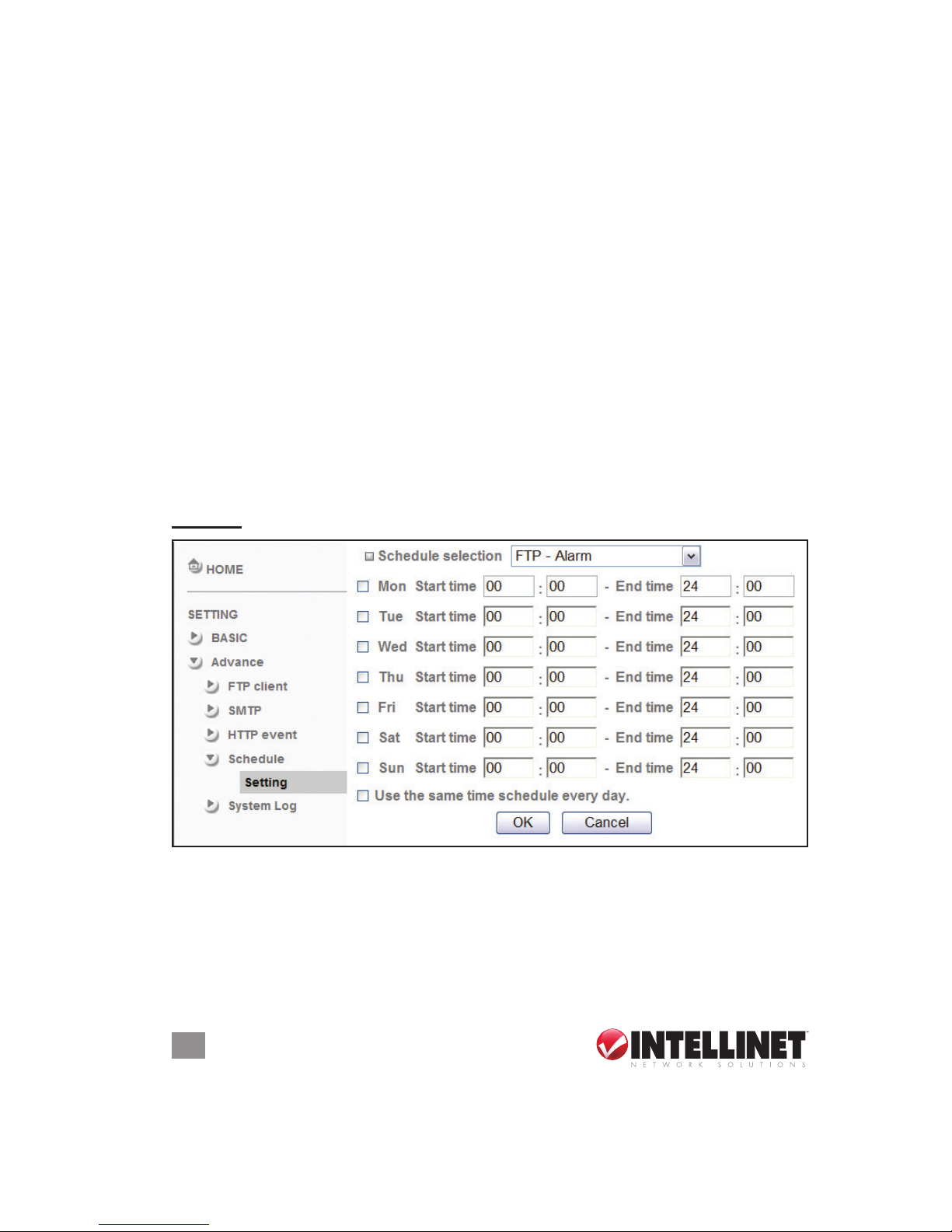
SCHEDULE
This is the same screen that’s displayed when you click “Schedule” in
FTP Client, SMTP and other sections.
Setting
Schedule selection — Using the drop-down menu, select the schedule
you want to set: “E-mail (SMTP) – Alarm,” “E-mail (SMTP) – Periodic,”
“FTP – Alarm,” “FTP – Periodic,” “HTTP event – Alarm,” “Alarm
output – Alarm” or “Alarm output – Timer.”
Mon (Monday) to Sun (Sunday) — The time period to the right of the
selected day is the effective period of the schedule.
Page 37
37
OPERATION
Start time, End time — Enter your preferences.
Use the same time schedule every day — When this is selected, the
start and end times set for Monday are applied to all days and the
times for the other days can’t be input.
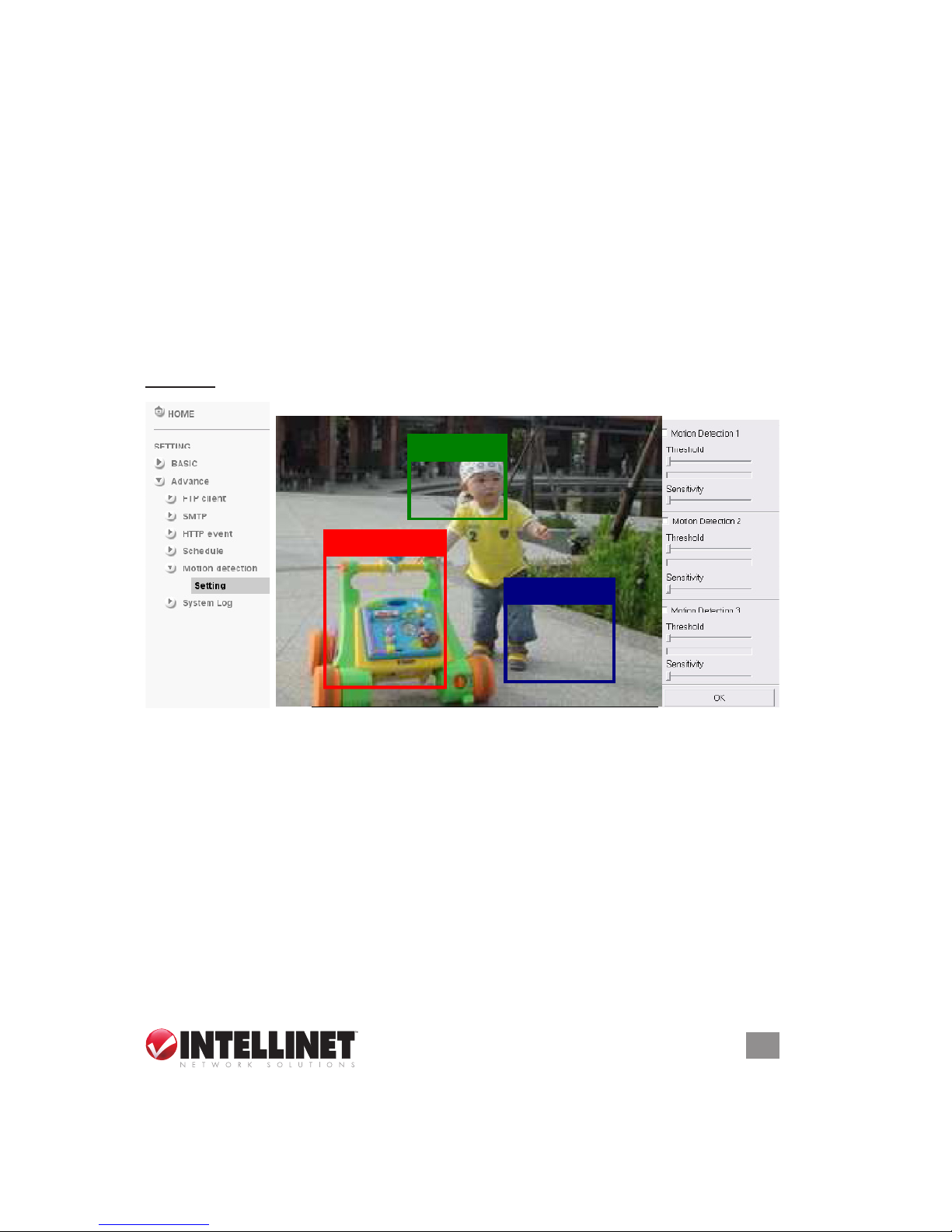
MOTION DETECTION
There are three zones covered by the Motion Detection function —
supporting FTP and SMTP (e-mail) — and each zone (1-3) has
Threshold and Sensitivity settings. When the function is enabled and
the rst detection zone displays, use the mouse to make adjustments
and move the zone boundaries and position.
Setting
Motion Detection 1–3 — Select to use the Motion Detection function as
a sensor. Adjust and move the detection zone by using your mouse.
Sensitivity — Position the slide-bar controller to suit your needs. The
higher the setting (to the right), the better the camera becomes at
discerning motion. At lower settings (to the left), the camera ignores
minor changes in the video images.
Threshold — Position the slide-bar controller to suit your needs. The
lower the setting (to the left), the more readily the camera triggers an
alarm event.
Page 38
38
OPERATION
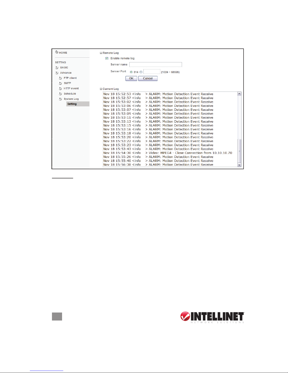
SYSTEM LOG
This screen displays any changes or events that have occurred.
Setting
Remote Log — Select to enable and send the log data to a specied
log server.
Page 39
39
TAB LES
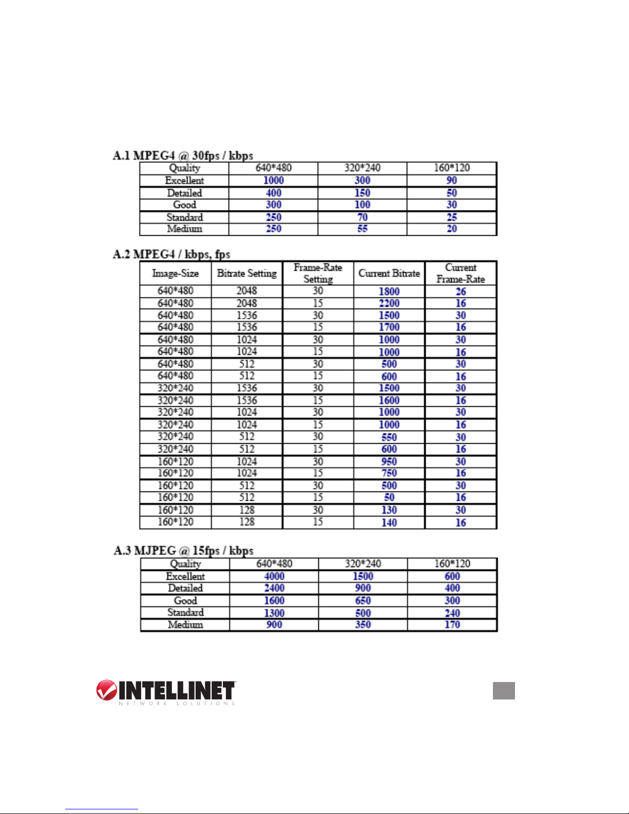
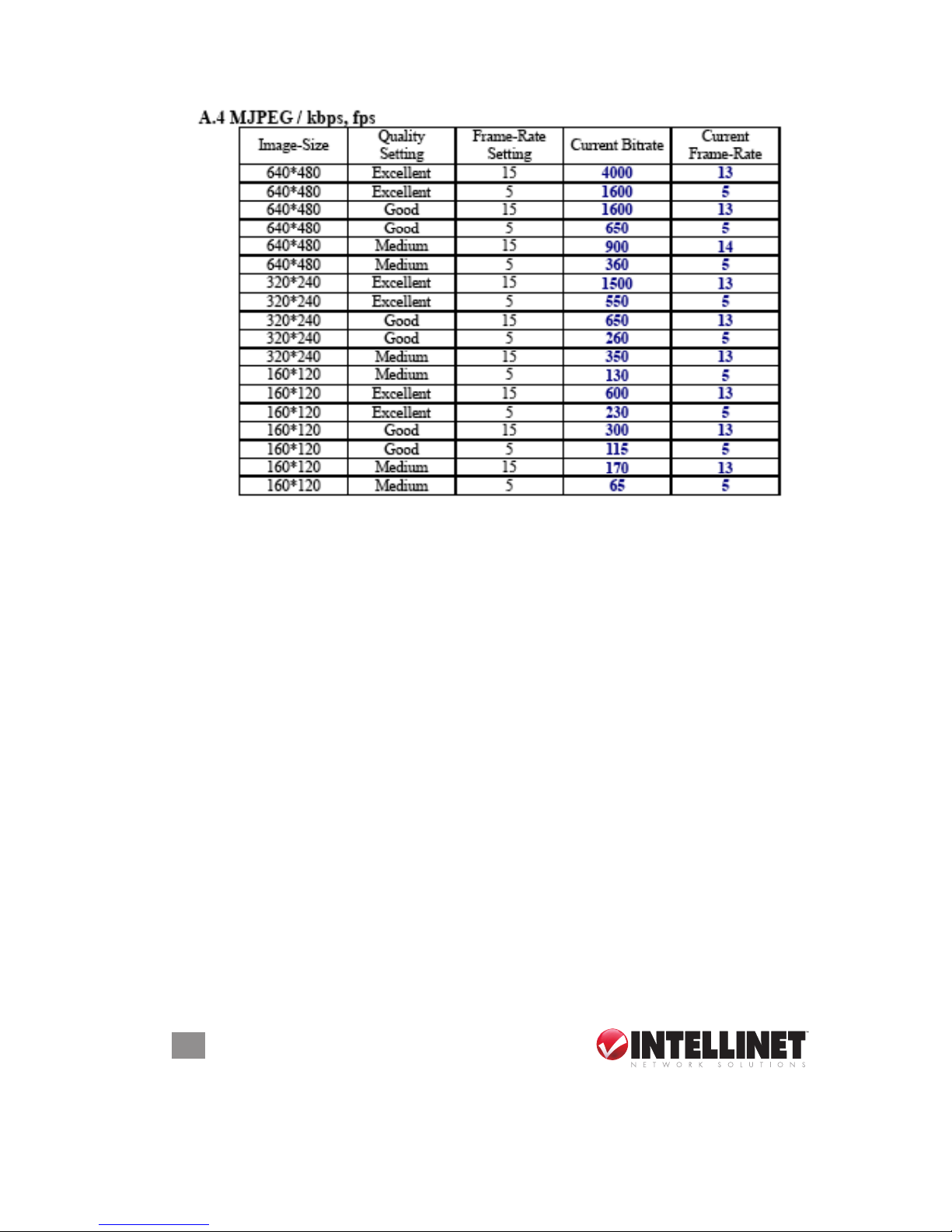
frame rate & bit rate tables
These tables can help guide you in optimizing the performance of your
SOHO Network Camera within your network environment.
Page 40
40
TAB LES
Page 41
41
TAB LES
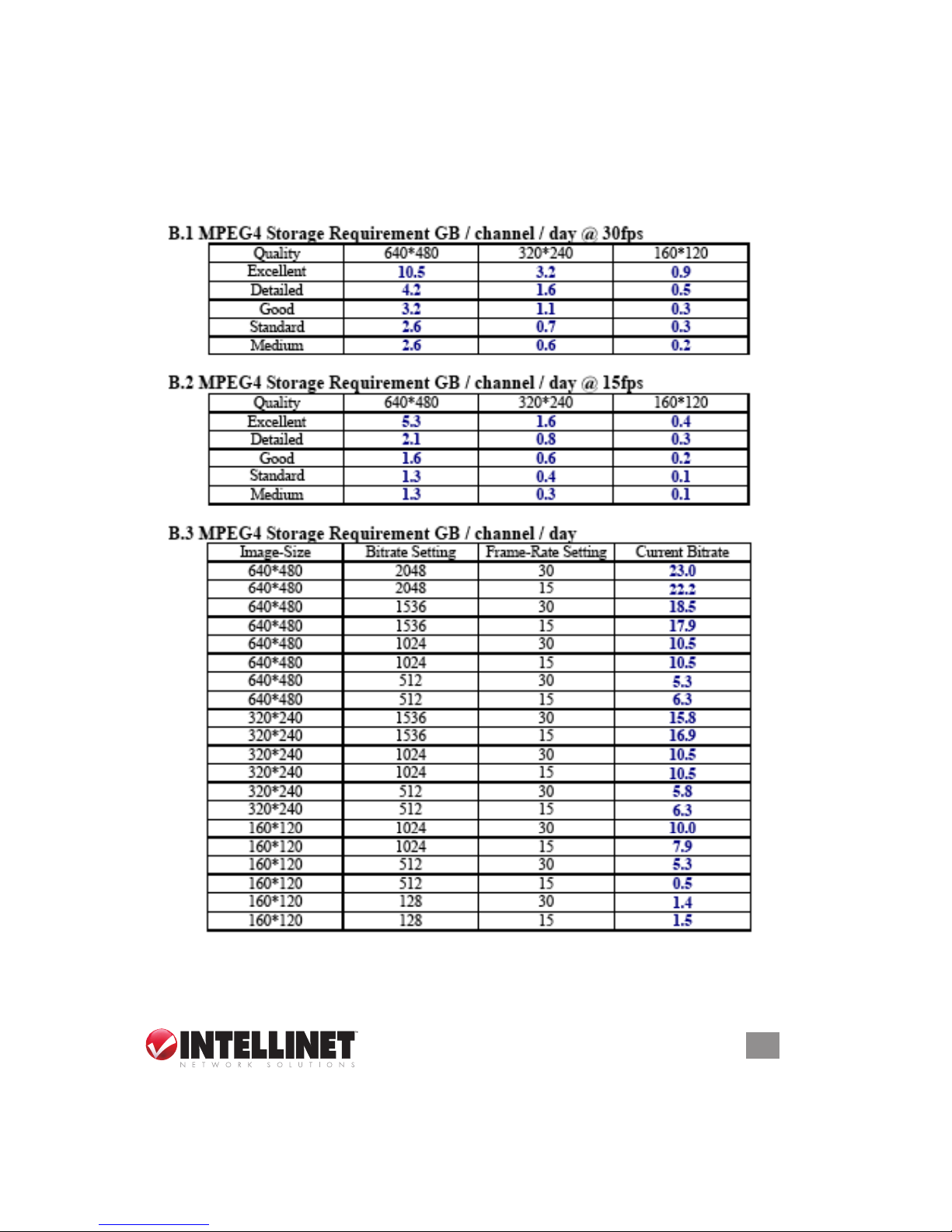
storage requirement tables
These tables can help you congure your recording storage system by
indicating your capability for recording onto your hard disk.
Page 42

42
SPECIFICATIONS
specifications
Standards
• IEEE 802.3 (10Base-T Ethernet)
• IEEE 802.3u (100Base-TX Fast Ethernet)
General
• 32-bit ARM9 RISC CPU
• 8 MByte ash memory
• 64 MByte SDRAM
• Supported image resolutions: 640 x 480;
320 x 240
• Video frame rate: max. 30 fps
• Audio support:
- Full duplex
- Bandwidth: G.711 PCM, 8 kHz, 64 kbit/s
- Microphone: built-in
- Audio line out jack: 3.5 mm / 1.8”
• Protocols supported: TCP/IP, DHCP,
PPPoE, ARP, ICMP, FTP, SMTP, DNS,
NTP, UPnP, RTSP, RTP, HTTP, TCP, UDP,
3GPP/ISMA RTSP
• Certications: FCC Class B, RoHS
Image Sensor and Lens
• Omnivision 1/4” progressive-scan CMOS
sensor with OmniPixel2 technology
• VGA resolution (664 H x 490 V)
• S/N ratio: 50 dB (max.)
• Pixel size: 6.0 µm x 6.0 µm
• Automatic Exposure Control (AEC),
Automatic Gain Control (AGC), Automatic
White Balance (AWB), Automatic Band
Filter (ABF) and Automatic Black-level
Calibration (ABLC)
• Manual brightness, contrast, saturation,
hue, sharpness control
• Minimum illumination: 0.5 lux at F2.0
• Focal length 4.0 mm, angular eld of view
59˚, object distance 0.2 m to innity
LEDs
• Power
• Network connection
Environmental
• Dimensions: 98 (W) x 58 (L) x 31 (H) mm
(3.8 x 2.3 x 1.2 in.)
• Weight: 0.6 kg (1.3 lbs.)
• Operating temperature: 0–45°C (32–113°F)
• Operating humidity: 20–80% RH,
non-condensing
Power
• External power adapter: 5 V DC, 1.2 A
• Power consumption: 3.5 Watts (maximum)
Page 43

Page 44

INTELLINET NETWORK SOLUTIONS™ offers a complete line
of active and passive networking products.
Ask your local computer dealer for more information or visit
www.intellinet-network.com.
Copyright © INTELLINET NETWORK
SOLUTIONS
All products mentioned are trademarks or registered trademarks of their respective owners.
 Loading...