

Intellinet 524360 (Annex A), 524377 User Manual
wireless n
ADsl2+ 4-port
mo
Dem router
user
mAnuAl
MODELS 524360 (ANNEX A)
& 524377 (ANNEX B)
INT-524360/524377-UM-1208-01
524360_524377_01_man.indd 1
12/18/08 2:23:36 PM

Contents
1 Introduction .......................................................................5
2 Hardware ..........................................................................6
Component Descriptions........................................................................... . 6
Setup/Installation................................................................ ...................7
3 Software/Setup Wizard ...................................................7
4 IP Address Settings ......................................................... 11
5 Web Management Configuration .................................. 13
Quick Start ...........................................................................14
Interface Setup ......................................................................15
Internet ..........................................................................15
LAN .............................................................................17
Wireless ........................................................................19
Advanced Setup ...................................................................23
Firewall..........................................................................23
Routing ..........................................................................23
NAT .............................................................................24
ADSL ............................................................................26
Access Management .............................................................27
ACL ..............................................................................27
IP Filter ..........................................................................27
SNMP ..........................................................................30
UPnP .............................................................................30
DDNS ........................................................................... 31
Maintenance ........................................................................31
Administrator ................................................................... 31
Time Zone ......................................................................32
Firmware ........................................................................32
System Restart .................................................................33
Diagnostics ....................................................................33
Status ..................................................................................33
Device Information ...........................................................33
System Log .....................................................................34
Statistics .........................................................................35
6 Troubleshooting ..............................................................35
7 Glossary ..........................................................................37
8 Specifications ..................................................................40
2
CONTENTS
section page
524360_524377_01_man.indd 2 12/18/08 2:23:37 PM

fCC regulAtory stAtements
FCC Part 68
This equipment complies with Part 68 of FCC Rules. On the bottom of this device is
a label with the FCC registration number and ringer equivalence number (R
EN) for
this equipment. You must provide this information to the telephone company upon
request. The REN is useful to determine the quantity of devices you may connect to
the telephone line and still have all of those devices ring when your number is called.
In most areas, the total of the R
EN of all devices connected to one line should not
exceed five. To be certain of the number of devices you may connect to your line,
as determined by the REN, contact your local telephone company.
If the modem causes harm to the telephone network, the telephone company may
discontinue your service temporarily, notifying you in advance (if feasible) or as
soon as possible. You will be advised of your right to file a complaint with the FCC.
Also, the telephone company may make changes in its facilities, equipment,
operations or procedures that could affect the proper operation of your equipment.
If they do, you will be notified in advance to give you an opportunity to maintain
uninterrupted telephone service.
If you experience trouble with this device, contact your I
NTELLINET NETWORK
SOLUTIONS
™
dealer for repair/warranty information. The telephone company
may ask you to disconnect this equipment from the network until the problem has
been corrected or until you are sure that the equipment is not malfunctioning.
This equipment may not be used on coin service provided by the telephone
company. Connection to party lines is subject to state tariffs.
Installation
This device is equipped with a US
OC RJ11C connector.
FCC Part 15
This equipment has been tested and found to comply with the limits for a Class
B
digital device, pursuant to Part 15 of FCC Rules. These limits are designed to provide
reasonable protection against harmful interference in a residential installation. This
equipment generates, uses and can radiate radio frequency energy and, if not
installed and used in accordance with the instructions, may cause harmful interference
to radio communications. However, there is no guarantee that interference will not
occur in a particular installation. If this equipment does cause harmful interference to
radio or television reception, which can be determined by turning the equipment off
and on, the user is encouraged to try to correct the interference by one or more of
the following measures:
1. Reorient or relocate the receiving antenna.
2. Increase the separation between the equipment and receiver.
3. Connect the equipment into an outlet on a circuit different from that to which the
receiver is connected.
4. Consult the dealer or an experienced radio technician for help.
3
REGULATORY NOTES AND STATEMENTS
524360_524377_01_man.indd 3 12/18/08 2:23:37 PM

FCC Caution
This equipment must be installed and operated in accordance with provided
instructions, and a minimum of 20 cm spacing must be provided between computermounted antenna and a person’s body (excluding extremities of hands, wrists and
feet) during wireless modes of operation.
This device complies with Part 15 of FCC Rules.
Operation is subject to the following two
conditions: (1) this device may not cause harmful interference, and (2) this device
must accept any interference received, including interference that may cause
undesired operation. Any changes or modifications not expressly approved by the
party responsible for compliance could void the authority to operate equipment.
Federal Communications Commission (FCC) Radiation Exposure Statement
This equipment complies with FCC radiation exposure limits set forth for an
uncontrolled environment. In order to avoid the possibility of exceeding the FCC
radio frequency exposure limits, human proximity to the antenna shall not be less
than 20 cm (8 inches) during normal operation. The antenna(s) used for this
transmitter must not be co-located or operating in conjunction with any other
antenna or transmitter.
R&TTE Compliance Statement
This equipment complies with all the requirements of
Directive 1999/5/EC of the
European Parliament and the Council of March 9, 1999, on radio equipment and
telecommunications terminal equipment and the mutual recognition of their conformity
(R&TTE), which repealed and replaced Directive 98/13/EEC (Telecommunications
Terminal
Equipment and Satellite Earth Station Equipment) as of April 8, 2000.
Safety
This equipment is designed with the utmost care for the safety of those who install
and use it. However, special attention must be paid to the dangers of electric
shock and static electricity when working with electrical equipment. All guidelines
of the FCC and of the computer manufacturer must therefore be followed at all
times to ensure the safe use of the equipment.
EU Countries Intended for Use
The
ETSI version of this device is intended for home and office use in Austria,
Belgium, Denmark, Finland, France, Germany, Greece, Ireland, Italy, Luxembourg,
the
Netherlands, Portugal, Spain, Sweden and the United Kingdom.
The ETSI version of this device is also authorized for use in EFTA member states
Iceland, Liechtenstein, Norway and Switzerland.
EU Countries Not Intended for Use
None.
NOTE: Some screen images have been modified to fit the format of this manual.
4
REGULATORY NOTES & STATEMENTS
524360_524377_01_man.indd 4 12/18/08 2:23:38 PM

1 introDuCtion
Thank you for purchasing this I
NTELLINET NETWORK SOLUTIONS
™
Wireless N
ADSL2+ 4-Port Modem Router, Model 524360 (Annex A) or Model 524377
(Annex
B). An all-in-one modem, router, Wireless N access point, firewall and
Fast Ethernet 4-port switch, it allows you to access the Internet and download music,
play interactive games online or surf the Web at double the speed previously
available through A
DSL2.
Improved modulation efficiency reduces framing overhead, achieves higher
coding gain, improves the initialization time and provides enhanced signalprocessing algorithms. ADSL2 increases downstream data rates to more than
12 Mbps (as compared to between 8 and 10 Mbps for original A
DSL) and can
extend reach by approximately 600 feet. With the ADSL2+ standard doubling
the maximum frequency used for downstream data transmission (from 1.1 MHz
to 2.2 MHz), the Wireless
N ADSL2+ 4-Port Modem Router effectively provides
downstream data rates of 24 Mbps on standard copper phone lines up to 5,000 feet.
Real-time performance-monitoring capabilities provide information regarding line
quality and noise conditions at both ends of the line. Service providers can use the
data to monitor the quality of your A
DSL connection to prevent service failures and
keep your connection up and running without disruption.
With these additional features, this router provides improved interoperability, fast
startup and enhanced voice support.
•
Advanced 2T3R MIMO technology for enhanced throughput and coverage
• Supports ADSL standards G.992.1 (G.dmt), G.992.2 (G.lite), G.992.3 (ADSL2),
G.992.4 (splitterless ADSL2) and G.992.5 (ADSL2+) for Annex A (Model
524360) or Annex B (Model 524377)
• Supports Wi-Fi Protected Setup (WPS)
• Supports WEP and WPA/WPA2 (TKIP and AES) data encryption
•
Integrated 10/100 Mbps LAN switch with Auto MDI/MDI-X support
• DHCP server assigns IP addresses and supports static lease management
• Supports virtual server and DMZ (demilitarized zone)
•
Supports DDNS (dynamic DNS)
• Supports UPNP (Universal Plug and Play)
• Integrated SPI rewall
•
VPN Pass Through (PPTP, IPSec)
• Supports SNMP management
• Complies with 2.4 GHz Draft IEEE 802.11n standard and is backward
compatible with IEEE 802.11g/b standards
•
Easy installation through Web-based user interface
• System Status and Security Log
• Firmware Upgradeable
•
Lifetime Warranty
5
INTRODUCTION
524360_524377_01_man.indd 5 12/18/08 2:23:38 PM
6
HARDWARE
2 hArDwAre
Component DesCriptions
Front Panel
As listed below, the LEDs indicate the current status of the router.
LED Mode Status
PWR (green) On Ready for operation.
WLAN (yellow) Off The wireless LAN is disabled.
Blinking Wireless traffic is being transmitted/received.
WPS (Yellow) Off WPS function is disabled.
Blinking WPS function is enabled.
ADSL (green) On Successful connection to an ADSL DSLAN.
Blinking No connection.
LAN (LNK/ACT) On The LAN cable is connected to the router.
Ports 1-4 (green) Off No network connection.
Blinking Network traffic is being transmitted/received.
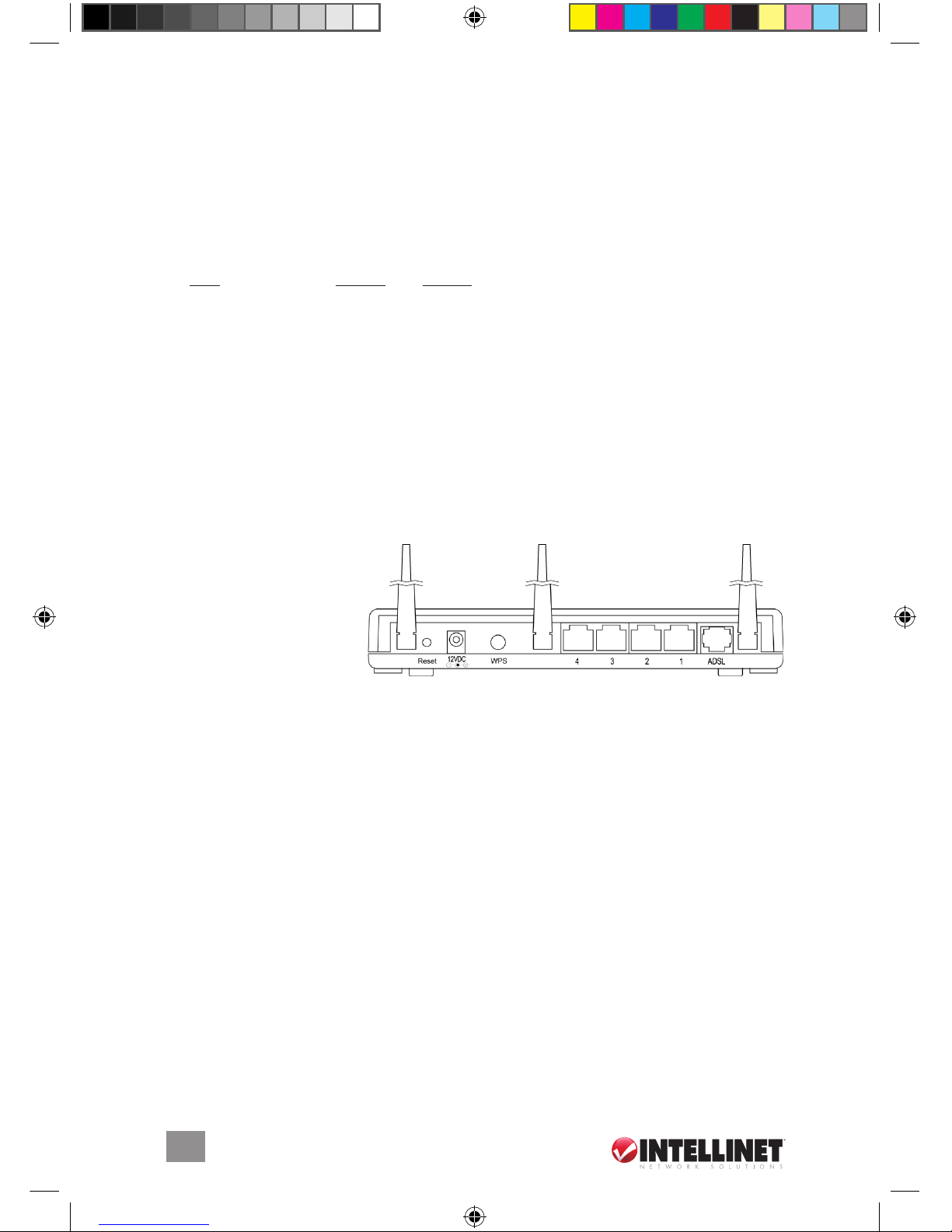
Rear Panel
Antenna Connectors: The
reverse SMA connectors
allow easy connection
to external antennas.
Reset button: This can be used to reset the router or to restore the factory default
settings. Press the button (using a pencil tip can help) for less than five seconds
to re-boot the router and save any configurations that have been set up.
If problems persist after a simple re-boot — or if you’ve forgotten your password —
hold the button in for longer than five seconds to reset the router to its factory
default settings. NOTE: The factory default settings will replace any others that
have been configured.
Power outlet: The included 12 V DC power adapter is connected here.
WPS button: Wi-Fi Protected Setup (WPS) is the simplest way to build a connection
between wireless network clients and this router. Press this button and enable the
WPS function of the wireless clients; the router and clients will automatically
configure the security key and connect directly. NOTE: The router will wait for
WPS requests from wireless clients for 2 minutes after the WPS button is pressed.
LAN ports: The four local area network (
LAN) ports are for connections to PCs,
LANs, printers, servers, hubs and so forth.
ADSL: The included RJ-11 phone line connects this to an A
DSL/phone network.
524360_524377_01_man.indd 6
12/18/08 2:23:40 PM
setup/instAllAtion
Once you’re familiar with the front and rear panels of the Wireless N ADSL2+
4-Port Modem Router, the setup and installation of the device is easy.
1.
From the ADSL port, connect the router to your ADSL network using the RJ-11
telephone cable provided.
2. From any of the LAN ports, connect the router to your PC, hub, switch or other
component using the Ethernet Cat5 RJ-45 cable provided.
3. Connect the router’s power outlet to a power source using the power adapter
provided. NOTE: Use only the power adapter included with this device.
4. Check that the green ADSL LED is on, indicating a successful connection. If
the ADSL LED is blinking — indicating that no connection has been made —
contact your Internet service provider.
3 softwAre/setup wizArD
This router provides a setup wizard to configure the ADSL settings. It collects and
enters ADSL settings from some Internet service providers (ISPs) simply by selecting
the ISP when prompted. If you can’t find your particular ISP listed in the wizard, go
ahead and manually input the ISP information through the wizard.
Before starting:
• Make sure the ADSL cable is connected to the router correctly. When the
ADSL cable is working normally, the ADSL LED will be on.
• Uninstall all dial-up programs previously installed for the USB modem or
other dial-up devices.
•
It is recommended that the router rst be congured with the Ethernet cable
connected prior to setting the wireless functions.
NOTE: This setup wizard can be run in Windows 2000, XP or Vista. The
following procedures and screen images represent Windows
XP, but are similar
for the other platforms.
1. Insert the enclosed setup CD (featuring the setup wizard) into your CD-ROM
drive. The Autorun.exe program should execute automatically. If not, run
Autorun.exe manually from the “Autorun” folder on the CD.
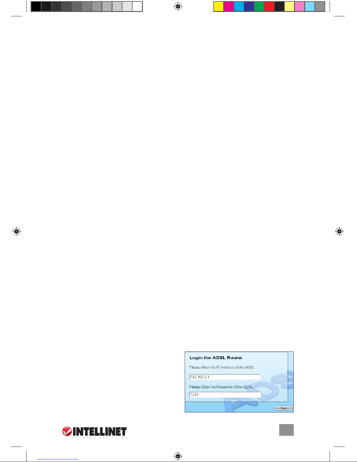
2. Click on “Setup Wizard” when the
initial menu appears on screen. The
wizard will search for the router. If
the router can’t be found, enter the
IP address and the password of the
router, then click “Next” to search
again.
7
SOFTWARE/SETUP WIZARD
524360_524377_01_man.indd 7 12/18/08 2:23:40 PM
8
SOFTWARE/SETUP WIZARD
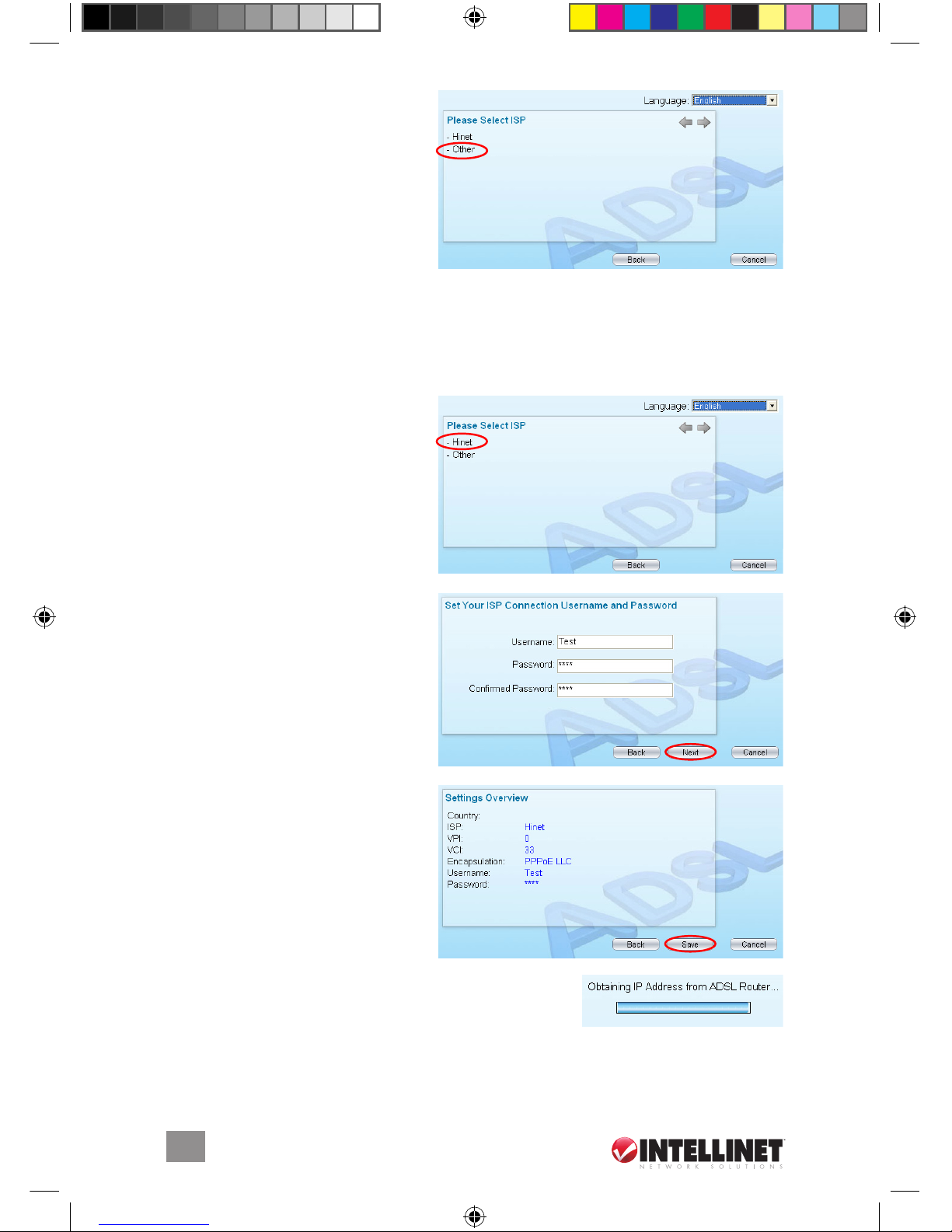
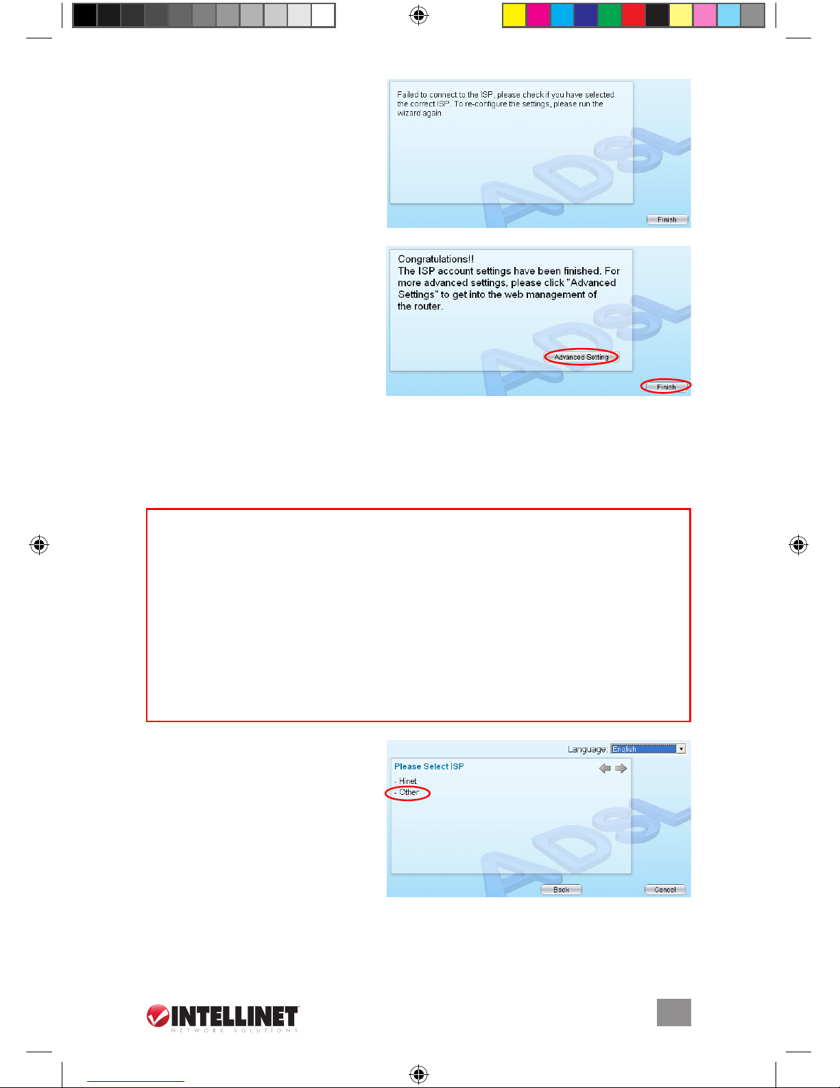
3. The wizard will automatically
select the country you’re in (by
identifying the language of the
computer’s operating system),
and will then display the Select
ISP screen. Select the ISP. If it’s
not listed, click “Other” to re select the country, or manually
configure the ISP information (see Manually Set ISP below).
Automatically Set ISP
If the Select ISP screen does list your ISP, follow these steps so the wizard can
configure the ISP settings automatically.
1.
As shown in the sample screen
at right, select the ISP of your
ADSL service.
2. If needed, enter the username
and password provided by
your ISP, then click “Next.”
3. When the Settings Overview
screen appears, click “Save,”
which will reboot the router.
After saving and rebooting, the
ISP settings are complete.
NOTE: To use the router to access
the Internet, the IP address of each
PC has to be set in the same
subnet as the router. This wizard will help to set the
proper IP address(es), and will display a status screen
(right) indicating so.
N
OTE: By default, the router’s DHCP server is enabled. If it is disabled before
running the setup wizard, the wizard will automatically enable it.
Your countr y
524360_524377_01_man.indd 8
12/18/08 2:23:41 PM
9
SOFTWARE/SETUP WIZARD
4. The wizard will try to connect
to the ISP you have selected.
If the connection fails, run the
wizard to select the ISP again.
5. With a successful ISP
connection, the Congratulations
confirmation screen will display.
To move on to the Web
management of the router, click
“Advanced Settings”; to close
the wizard, click “Finish.”
Manually Set ISP
If the ISP can’t be located using the wizard, follow the steps below to configure
the ISP settings manually. Confirm what kind of service is being provided — as
shown here — and keep the information for future reference.
1.
On the Select ISP screen, select
“Ot her.”
PPPoE VPI/VCI, VC-based/LLC-based multiplexing, Username,
Password (and Service Name).
PPPoA
VPI/VCI, VC-based/LLC-based multiplexing, Username,
Password.
RFC1483 Bridged VPI/VCI, VC-based/LLC-based multiplexing to use
Bridged Mode.
RFC1483 Routed
VPI/VCI, VC-based/LLC-based multiplexing, IP Address,
Subnet Mask, Gateway Address and Domain Name
System (DNS) IP Address (a fixed IP Address).
524360_524377_01_man.indd 9 12/18/08 2:23:42 PM
10
SOFTWARE/SETUP WIZARD
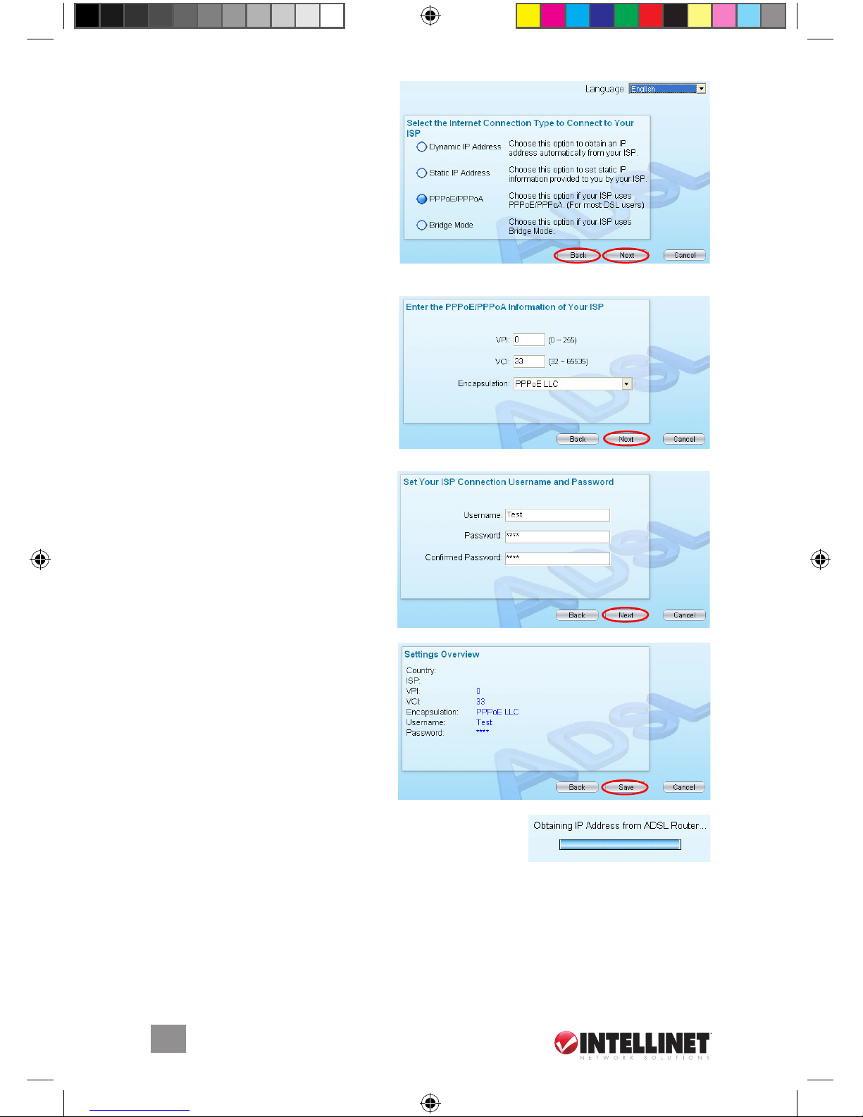
2. With the Select the Internet
Connection Type...” screen
displayed, make a selection
and click “Next.” NOTE: The
wizard will automatically select
the country that you’re in (by
identifying the language of the
computer’s operating system),
and will then display the Select
ISP screen. If you want to change the country, click “Back” instead of “Next.”
3. In the VPI, VCI and Encapsulation
fields, enter the data provided
by your ISP. If the connection
type is static IP address, enter
the IP address information
provided by your ISP. (For
details, see Web Management /
Interface Setup.) Click “Next.”
4. If needed, enter your username
and password (twice) in the
corresponding fields. Click
“Next.”
5.
When the Settings Overview
screen appears, click “Save,”
which will reboot the router.
After saving and rebooting, the
ISP settings are complete.
NOTE: To use the router to access
the Internet, the IP address of each
PC has to be set in the same
subnet as the router. This wizard will help to set the
proper IP address(es), and will display a status screen
(right) indicating so.
N
OTE: By default, the router’s DHCP server is enabled. If it is disabled before
running the setup wizard, the wizard will automatically enable it.
Other
Other
524360_524377_01_man.indd 10 12/18/08 2:23:43 PM
11
IP ADDRESS SETTINGS
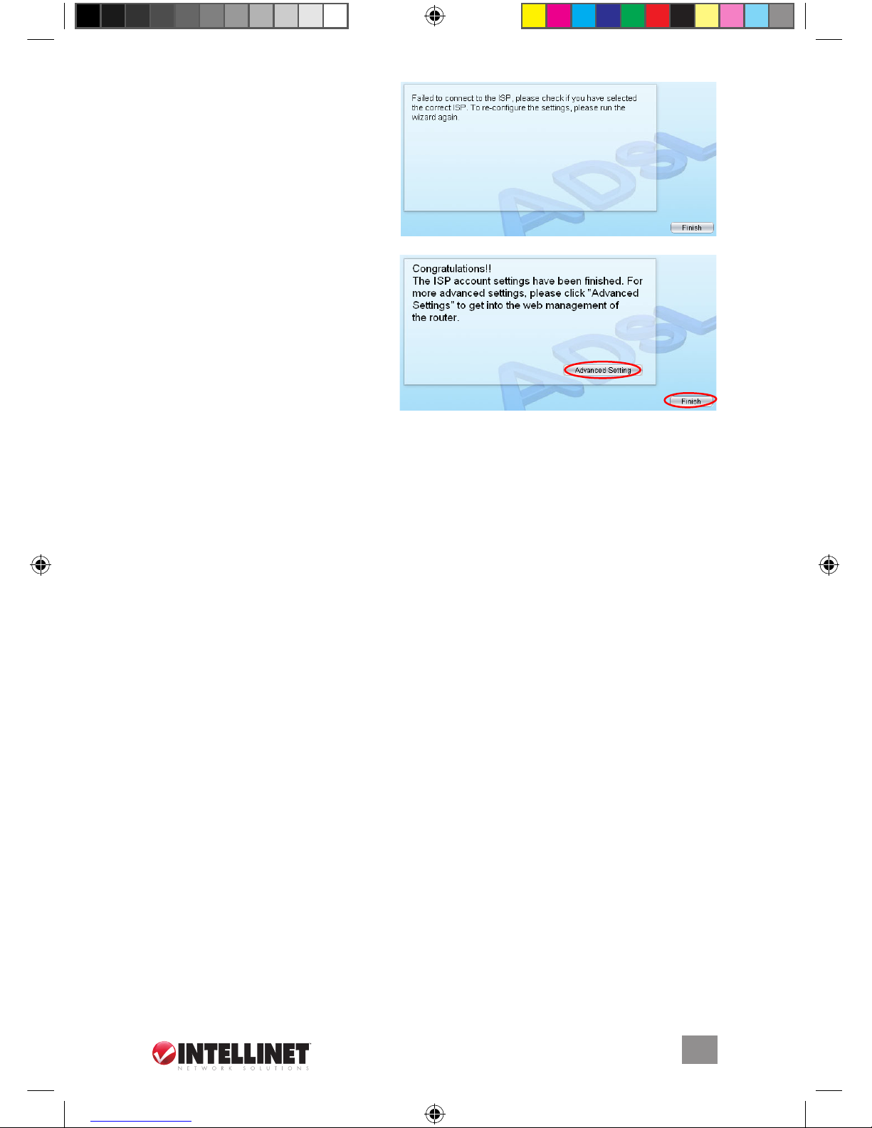
6. The wizard will try to connect
to the ISP you have selected.
If the connection fails, run the
wizard to select the ISP again.
7. With a successful ISP
connection, the Congratulations
confirmation screen will display.
To move on to the Web
management of the router, click
“Advanced Settings”; to close
the wizard, click “Finish.”
4 ip ADDress settings
As noted above, to use the router to access the Internet, the PCs in the network
must have an Ethernet adapter installed and be connected to the router either
directly or through a hub or switch. The TCP/IP protocol of each PC has to be
installed, and the IP address of each PC has to be set in the same subnet as
the router.
The router’s default IP address is
19 2.16 8. 2.1; the subnet mask is 255.255.255.0.
PCs can be configured to obtain an IP address automatically through the
DHCP
server of the router or a fixed IP address in order to be in the same subnet as the
router. By default, the DHCP server of the router is enabled and will dispatch an
IP address to the PC from between 192.168.2.100 and 192.168.2.200. It is
strongly recommended that IP addresses be set/obtained automatically.
This section explains how to configure a PC so that it can obtain an IP address
automatically for Windows 2000, XP or Vista. For other operating systems
(Macintosh, Sun, etc.), follow the manual of that operating system.
Windows Vista
1.
Click “Start,” select “Settings,” then go to the control panel and double-click
“Network and Sharing Center” to display its window.
2. Click “Manage network connections,” right-click on the Local Area Connection
icon and select Properties. The Local Area Connection screen will display.
3. Check the list of Network Components. You should see “Internet Protocol
Version 4 (TCP/IPv4)” on your list. Select it and click Properties.
524360_524377_01_man.indd 11 12/18/08 2:23:44 PM
12
IP ADDRESS SETTINGS
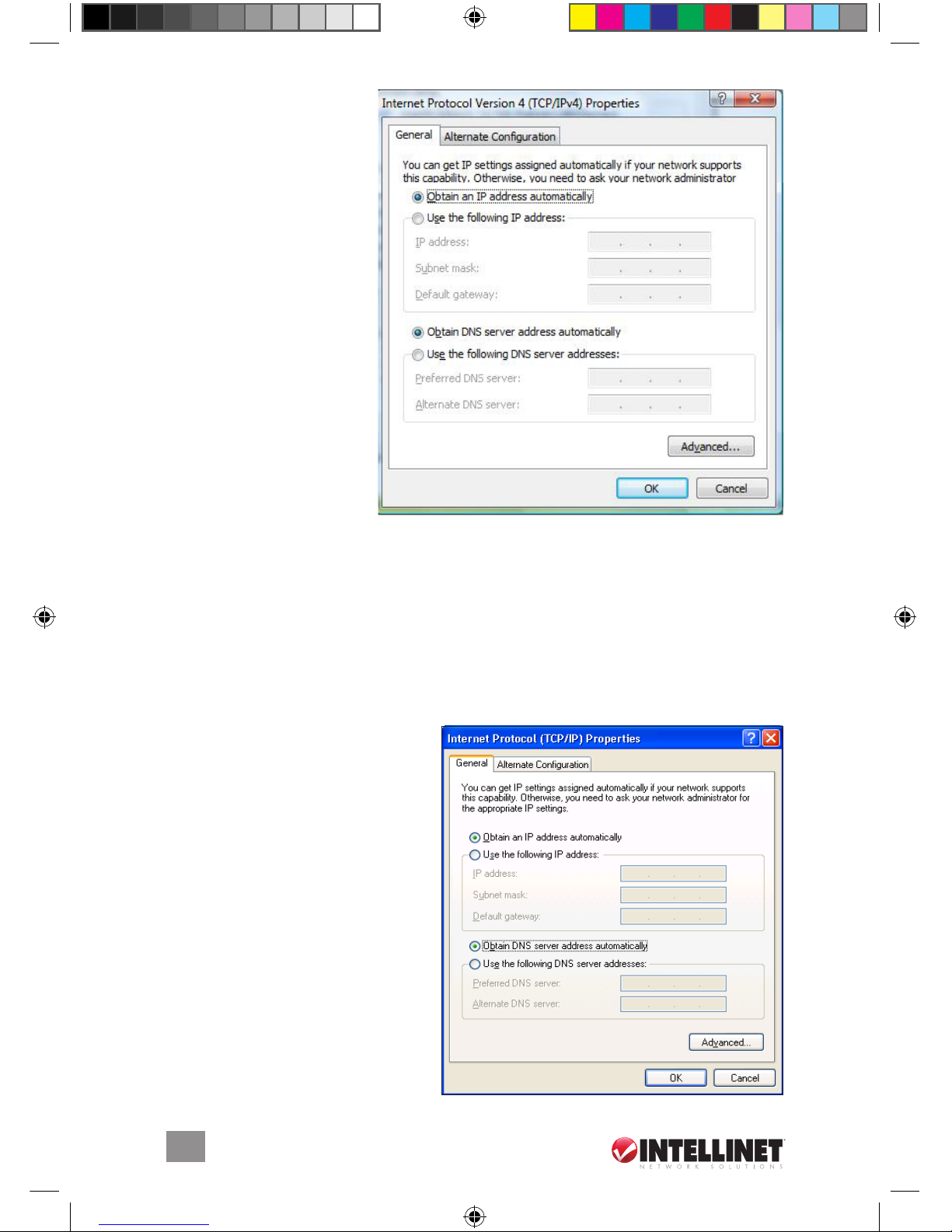
4. On the Internet Protocol
Version 4 (TCP/IPv4)
Properties screen, select
“Obtain an IP address
automatically” and
“Obtain DNS server
address automatically.”
5. Click “OK” to confirm
the setting. Your PC will
obtain an IP address
automatically from the
router’s DHCP server.
NOTE: Make sure that the
router’s
DHCP server is the
only one available on your
LAN.
Windows XP
1. Click “Start,” open the control panel and then double-click “Network
Connections.” The Network Connections window will appear.
2. Right-click on the Local Area Connection icon and select Properties. The Local
Area Connection window will appear.
3. Check the list of Network Components. You should see “Internet Protocol
(TCP/IP)” on your list. Select it and click Properties.
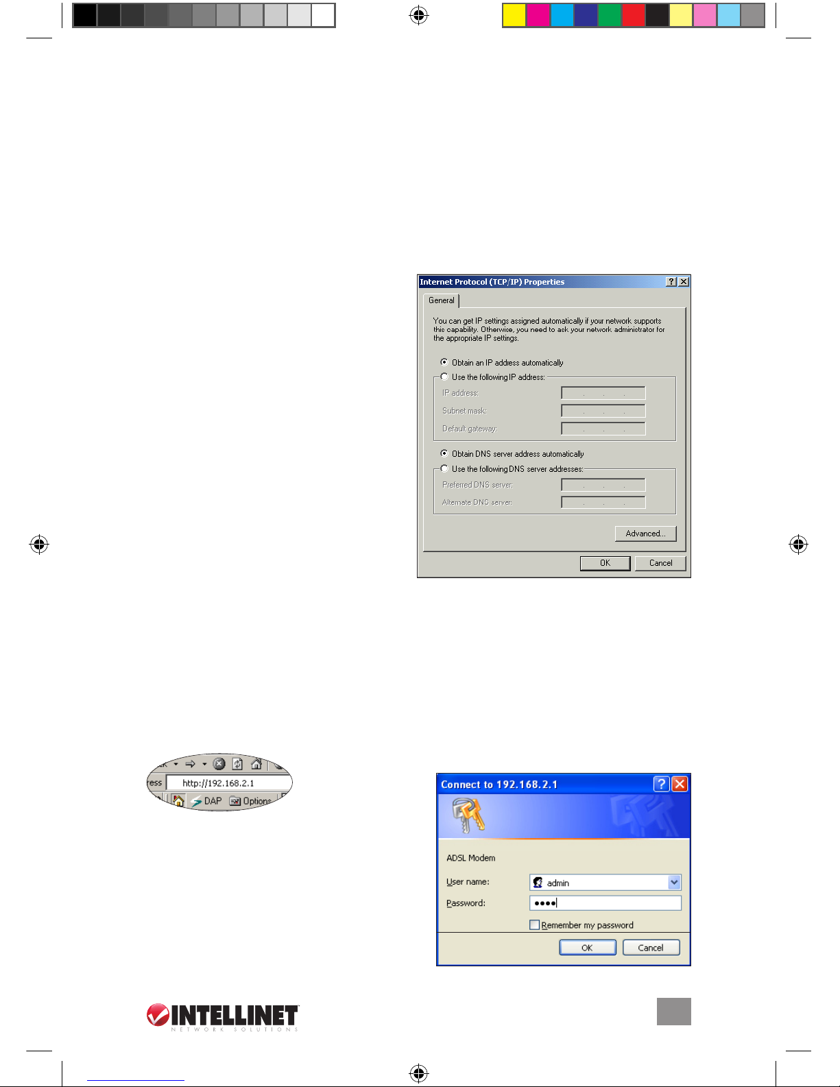
4. In the Internet Protocol (TCP/IP)
Properties window, select “Obtain
an IP address automatically” and
“Obtain DNS server address
automatically.”
5. Click “OK” to confirm the setting.
Your PC will now obtain an IP
address automatically from the
router’s DHCP server.
NOTE: Make sure the router’s
DHCP server is the only one
available on your LAN.
524360_524377_01_man.indd 12 12/18/08 2:23:45 PM
13
WEB MANAGEMENT
Windows 2000
1. Click “Start” and select Settings, then click “Control Panel.”
2. Double-click on the Network and Dial-up Connection icon. In the Network
and Dial-up Connection window, double-click on the Local Area Connection
icon. The Local Area Connection window will appear.
3. In the Local Area Connection window, click “Properties.”
4. Check your list of
Network Components. You should see “Internet Protocol
(TCP/IP)” on your list. Select it and click “Properties.”
5. In the Internet Protocol (TCP/IP)
Properties window, select “Obtain
an IP address automatically” and
“Obtain DNS server address
automatically.”
6.
Click “OK” to confirm the setting.
Your PC will obtain an IP address
automatically from your router’s
DHCP server.
NOTE: Make sure the router’s DHCP
server is the only one available on your
LAN.
5 web mAnAgement
After configuring the PC(s) to obtain the IP address(es) automatically, the router’s
DHCP server will automatically give LAN clients an IP address. By default, the server
is enabled so that an IP address can be obtained automatically.
Once the PC has obtained an IP address from the router, enter the default IP
address
19 2.16 8.2 .1 (the router’s IP address) into the PC’s
Web browser and
press “Enter.”
The login screen will appear.
Enter the
username and password, then click “OK”
to log in. By default, the username is
“admin”; the password is “1234.” For
security reasons, it’s recommended that the
password be changed as soon as possible.
Click “
OK” to continue.
524360_524377_01_man.indd 13 12/18/08 2:23:45 PM
14
WEB MANAGEMENT
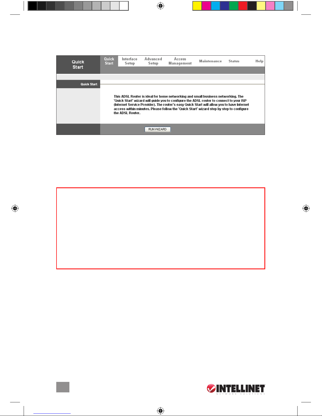
The Home Page screen appears, displaying seven instructional options: Quick
Start, Interface Setup, Advanced Setup, Access Management, Maintenance,
Status and Help.
quiCk stArt
The Quick Start section is designed to get you using the router as quickly as
possible.
Before configuring the router, check with your ISP (Internet service
provider) as to what kind of service is provided (examples shown below).
1. Click “Run Wizard” to start the configuration; then click “Next” to continue
through the five subsequent Quick Start screens: Password, Time Zone, ISP
Connection Type, PPPoE/PPPoA and Complete.
2. Set and confirm the new password; click “Next” to continue.
3. Select the time zone; click “Next” to continue.
4. Select your Internet connection type (as directed by your ISP, with examples
shown above); click “Next” to continue.
5. Enter the data provided by your ISP. For details on each setting, see the
Interface Setup section below. Click “Next” to continue.
6. Restart your ADSL router. Click “Next” to save the settings and restart the
router.
PPPoE VPI/VCI, VC-based/LLC-based multiplexing, Username,
Password (and Service Name).
PPPoA
VPI/VCI, VC-based/LLC-based multiplexing, Username,
Password.
RFC1483 Bridged VPI/VCI, VC-based/LLC-based multiplexing to use
Bridged Mode.
RFC1483 Routed
VPI/VCI, VC-based/LLC-based multiplexing, IP Address,
Subnet Mask, Gateway Address and Domain Name
System (DNS) IP Address (a fixed IP Address).
524360_524377_01_man.indd 14 12/18/08 2:23:46 PM
 Loading...