

Intellinet 523868 User Manual
MANAGED
LAYER 3
ACCESS
SWITCH
USER
MANUAL
MODEL 523868
INT-523868-UM-0807-01


INTRODUCTION
Thank you for purchasing the INTELLINET NETWORK SOLUTIONS™ Managed Layer 3
Access Switch, Model 523868.
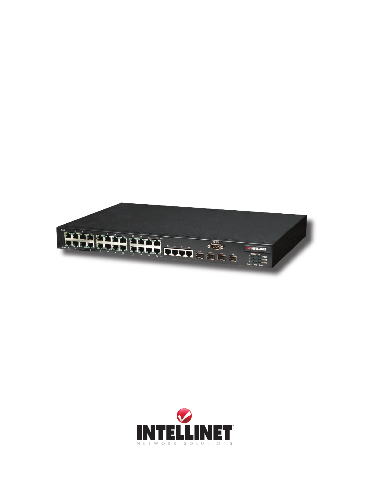
This is a high-performance managed SNMP switch that provides users with 24 10/100 Mbps
Ethernet and four Gigabit combo ports. The Web/SNMP management provides remote control
capability that gives exible network management and monitoring options. Whether managed
through an “in-band” SNMP management station, an Internet Web browser or an “out-of-band”
RS-232 console port, the Managed Layer 3 Access Switch facilitates network operational
control and diagnosis.
For increased bandwidth application, it can accommodate up to 32 trunk groups with LACP
link aggregation. Moreover, these trunk ports are set up with a fail-over function to provide
redundant backup if one or more ports are malfunctioning. It also supports both 802.1Q VLAN
and GVRP VLAN registration, thereby simplifying network trafc segmentation, broadcast domain
extension and other associated benets of constructing VLANs.
The abundance of popular features (highlighted below) translates into increased efciency and
performance in network administration, and the easy-to-follow instructions in this user manual
help make setup and operation quick and simple.
• Integrated 10/100 Mbps LAN switch with Auto MDI/MDI-X support
• Supports virtual server, port forwarding and DMZ (demilitarized zone)
• Supports DDNS (dynamic DNS)
• Supports VPN pass-through (IPSec, PPTP, L2TP)
• 94 Mbps WAN to LAN throughput for wired networks
• WOL (Wake-On LAN) function sends a wakeup signal to any computer in the LAN
• Integrated scheduler to limit Internet access to client computers in the LAN
• Remote management function (enable/disable and management port)
• Easy installation through Web-based user interface
• Firmware updates via Web-based user interface
• Lifetime Warranty
Package Contents
• Managed Layer 3 Access Switch
• Power cable
• 19” rackmount brackets
• User manual
FCC Warning
This equipment has been tested and found to comply with the limits for a class A device, pursuant
to part 15 of FCC rules. These limits are designed to provide reasonable protection against
harmful interference in a commercial installation. This equipment generates, uses and can
radiate radio frequency energy and, if not installed and used in accordance with the instructions,
may cause harmful interference to radio communication. Operation of this equipment in a
residential area is likely to cause harmful interference, in which case the user will be required
to correct the interference at the user’s own expense.
CE
This is a class A product. In a domestic environment, this product may cause radio interference,
in which case the user may be required to take adequate measures.
3
INTRODUCTION

TABLE OF CONTENTS
Introduction & FCC Warning ........................................................................................... 3
1 HARDWARE ................................................................................................................. 6
1.1 Front Panel Connections & Indicators ..................................................................... 6
1.1.1 10/100Base-TX Ports .................................................................................. 6
1.1.2 10/1001000Base-T Ports ............................................................................. 6
1.1.3 SFP Slots for SFP Modules ......................................................................... 6
1.1.4 LEDs ............................................................................................................ 6
1.2 Installation ............................................................................................................... 7
1.2.1 Location/Position ......................................................................................... 7
1.2.2 Powering On the Unit ................................................................................... 7
1.2.3 Installing the SFP Modules and Fiber Cable ............................................... 8
1.2.4 Connecting Copper Cable ........................................................................... 8
1.2.5 Connecting the Console Port Cable ............................................................ 8
1.2.6 Connecting to Computers or a LAN ............................................................ 8
2 SWITCH MANAGEMENT/OPERATION ........................................................................ 8
2.1 System Overview ..................................................................................................... 8
2.1.1 Conguration Using the Console Port (RS-232) ......................................... 9
2.1.1.1 Using HyperTerminal to Set the IP Address ................................ 9
2.1.2 Conguration Using Telnet and SSH ......................................................... 10
2.1.3 SNMP-Based Management and Settings ...................................................11
2.1.3.1 MIB Objects ................................................................................11
2.1.3.2 Traps ...........................................................................................11
2.1.4 Initial Connection to the Switch ..................................................................12
2.2 Web Management ..................................................................................................13
2.2.1 Login ...........................................................................................................13
2.2.2 System ........................................................................................................14
2.2.2.1 Management ...............................................................................14
2.2.2.2 IP Setup ......................................................................................14
2.2.2.3 Reboot ........................................................................................14
2.2.2.4 Firmware Upgrade ......................................................................14
2.2.3 Physical Interface .......................................................................................15
2.2.3.1 Interface Conguration ...............................................................15
2.2.3.2 Runtime Status ...........................................................................15
2.2.4 IP Interface ................................................................................................ 16
2.2.5 Router Reports .......................................................................................... 16
2.2.6 Routing ....................................................................................................17
2.2.6.1 Static Route ................................................................................17
2.2.6.2 RIP ..............................................................................................17
2.2.6.3 OSPF ..........................................................................................18
2.2.6.4 Multicast Route ...........................................................................19
section page
4
CONTENTS

2.2.6.5 VRRP ......................................................................................... 21
2.2.7 Bridge ......................................................................................................... 21
2.2.7.1 Spanning Tree ............................................................................ 21
2.2.7.2 Link Aggregation Static .............................................................. 23
2.2.7.3 LACP .......................................................................................... 24
2.2.7.4 Mirroring ..................................................................................... 25
2.2.7.5 Static Multicast ........................................................................... 25
2.2.7.6 IGMP Snooping ......................................................................... 26
2.2.7.7 Trafc Control ............................................................................ 27
2.2.7.8 Dynamic Addresses ................................................................... 27
2.2.7.9 Static Addresses ........................................................................ 28
2.2.7.10 VLAN Conguration ................................................................... 28
2.2.7.11 GVRP ......................................................................................... 29
2.2.7.12 Qos/CoS .................................................................................... 29
2.2.8 SNMP ..........................................................................................................31
2.2.8.1 Host Table ...................................................................................31
2.2.8.2 Trap Setting .................................................................................31
2.2.8.3 SNMPv3 VGU Table ...................................................................31
2.2.9 Filters ......................................................................................................... 33
2.2.9.1 Filter Set ..................................................................................... 33
2.2.9.2 Filter Attach ................................................................................ 34
2.2.10 Security ...................................................................................................... 34
2.2.10.1 Port Access Control ................................................................... 34
2.2.10.2 Dial-In User ................................................................................ 35
2.2.10.3 RADIUS ..................................................................................... 35
2.2.11 Trafc Chart ............................................................................................... 36
2.2.11.1 Trafc Comparison Chart........................................................... 36
2.2.11.2 Group Chart ............................................................................... 36
2.2.11.3 History Chart .............................................................................. 37
2.2.12 Save Conguration .................................................................................... 37
2.3 Command Line Interface ....................................................................................... 37
2.3.1 Power On ................................................................................................... 37
2.3.1.1 Boot ROM Command Mode ...................................................... 37
2.3.1.2 Boot ROM Commands ............................................................... 38
2.3.2 Login and Logout ....................................................................................... 38
2.3.3 CLI Commands .......................................................................................... 38
2.3.4 Miscellaneous Commands ........................................................................ 50
3 SPECIFICATIONS ........................................................................................................ 50
NOTE: Some screen-shot images have been modied to t the format of this user manual.
5
CONTENTS
1 HARDWARE
1.1 Front Panel Connections & Indicators
The Managed Layer 3 Access Switch utilizes ports with copper and SFP ber port connectors
functioning under Ethernet/Fast Ethernet/Gigabit Ethernet standards.
1.1.1 10/100Base-TX Ports
The 10/100Base-TX ports (1 above) support network speeds of either 10 Mbps or 100 Mbps,
and can operate in half- and full-duplex transfer modes. These ports also offer automatic MDI/
MDI-X crossover detection that gives true Plug and Play capability — just plug the network cables
into the ports and the ports will adjust according to the end-node devices. NOTE: Cat3 cables
or better are recommended for 10 Mbps connections; Cat5 or better for 100 Mbps.
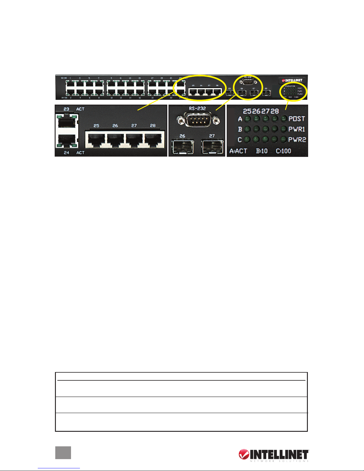
1.1.2 10/100/1000Base-T Ports
The switch has four Gigabit 10/100/1000Base-T ports (2 above)) for RJ-45 connectors that
have the same features as the above-mentioned 10/100 ports. The only difference is that the
Gigabit copper ports support network speeds of 10/100/1000 Mbps. These four ports are located
next to the four SFP-type ber slots, and each of these RJ-45 ports is interchangeable with a
corresponding SFP slot. The Gigabit copper port will have the same number as its corresponding
SFP slot. This means that once an SFP slot is connected, the corresponding RJ-45 port (25,
26, 27 or 28) won’t function.
1.1.3 SFP Slots for SFP Modules
The four SFP slots (3 above) are designed to house Gigabit SFP modules that support network
speeds of 1000 Mbps. These slots are interchangeable with the four 1000Base-T ports to their
left, and the slots have the same port numbers as their corresponding 1000Base-T ports. This
means that once an SFP slot is connected via an SFP module the correspondingly numbered
1000Base-T port (25, 26, 27 or 28) won’t function.
1.1.4 LEDs
The switch is equipped with Unit LEDs (4 above), which indicate the status of the device, and
Port LEDs, which display what is happening with all of the connections.
6
CONNECTIONS & INDICATORS
Unit LED Condition Status
POST Flashing Indicating POST (Power On Self Test) function upon start-up
On POST function successfully performed
PWR1 On (Green) Primary power normal
Off Primary power off or failure
PWR2 On (Green) Backup power normal
Off Backup power off or failure
4
4
3
3
2
2
1
1

7
INSTALLATION
1.2 Installation
1.2.1 Location/Position
The location of the switch can greatly affect its performance. Consider these guidelines before
placement, connection and operation.
• Choose a location that complies with the acceptable temperature and humidity ranges listed
in the Specications section.
• Avoid placing the switch in the vicinity of strong electromagnetic eld generators (such as
motors), vibration, dust and direct sunlight.
• Allow at least 10 cm of space at the front and rear of the unit for ventilation.
• As the switch is capable of connecting up to 28 network devices employing a combination of
twisted-pair and ber cabling paths, check that all cords/connectors can be safely secured.
You have three options for positioning the switch:
• For desktop use, choose a clean, at surface with convenient access to an AC power outlet
and afx the four included self-adhesive rubber pads to the bottom of the unit.
• For vertical mounting, use the underside of the switch as a template to measure and mark out
the position of the holes on the vertical surface where the unit is to be installed. Then use the
two screws provided to mount the switch rmly in place.
• For rack mounting, attach brackets to each side of the switch and place the brackets in the
rack’s slots. Insert and tighten two screws to secure the bracket to the rack on each side.
1.2.2 Powering On the Unit
The switch uses an AC power supply: 100–240 V AC / 50–60 Hz; or -48 V DC. The power on/
off switch is located at the rear of the unit, adjacent to the AC power connector and the system
fans. The switch’s power supply automatically self-adjusts to the local power source, and may
be powered on without having any or all LAN segment cables connected.
1. Plug the power cable directly into the receptacle located at the back of the device.
2. Plug the power adapter into an available socket. NOTE: For international use, you may need
to change the AC power adapter cord. Use only a power cord set that has been approved
for the receptacle type and electrical current in the country you’re in.
3. Check the front-panel LEDs as the device is powered on to verify that the PWR LEDs are
lit. If they’re not, check that the power cable is correctly and securely plugged in.
WarNiNg: Because invisible laser radiation may be emitted from the aperture of the
ports when no cable is connected, avoid exposure to laser radiation and do not stare
into open apertures.
Port LED Condition Status
10/100 On (green) Port operating at 100 Mbps
(copper) Off Port operating at below 100 Mbps
ACT On (green) Illuminated when connectors are attached
Flashing (green) Data trafc passing through port
Off No valid link established on port
A 25-28 On (green) Illuminated when connectors are attached
Gigabit E’net Flashing (green) Data trafc passing through port
Off No valid link established on port
B 25-28 On (green) Port is operating at 10 Mbps. If LED C is also on, port is
Gigabit E’net operating at 1000 Mbps
Off If LED C is on, port is operating at 100 Mbps or link is down
C 25-28 On (green) Port is operating at 100 Mbps. If LED B is also on, port is
Gigabit E’net operating at 1000 Mbps
Off If LED B is on, port is operating at 10 Mbps or link is down
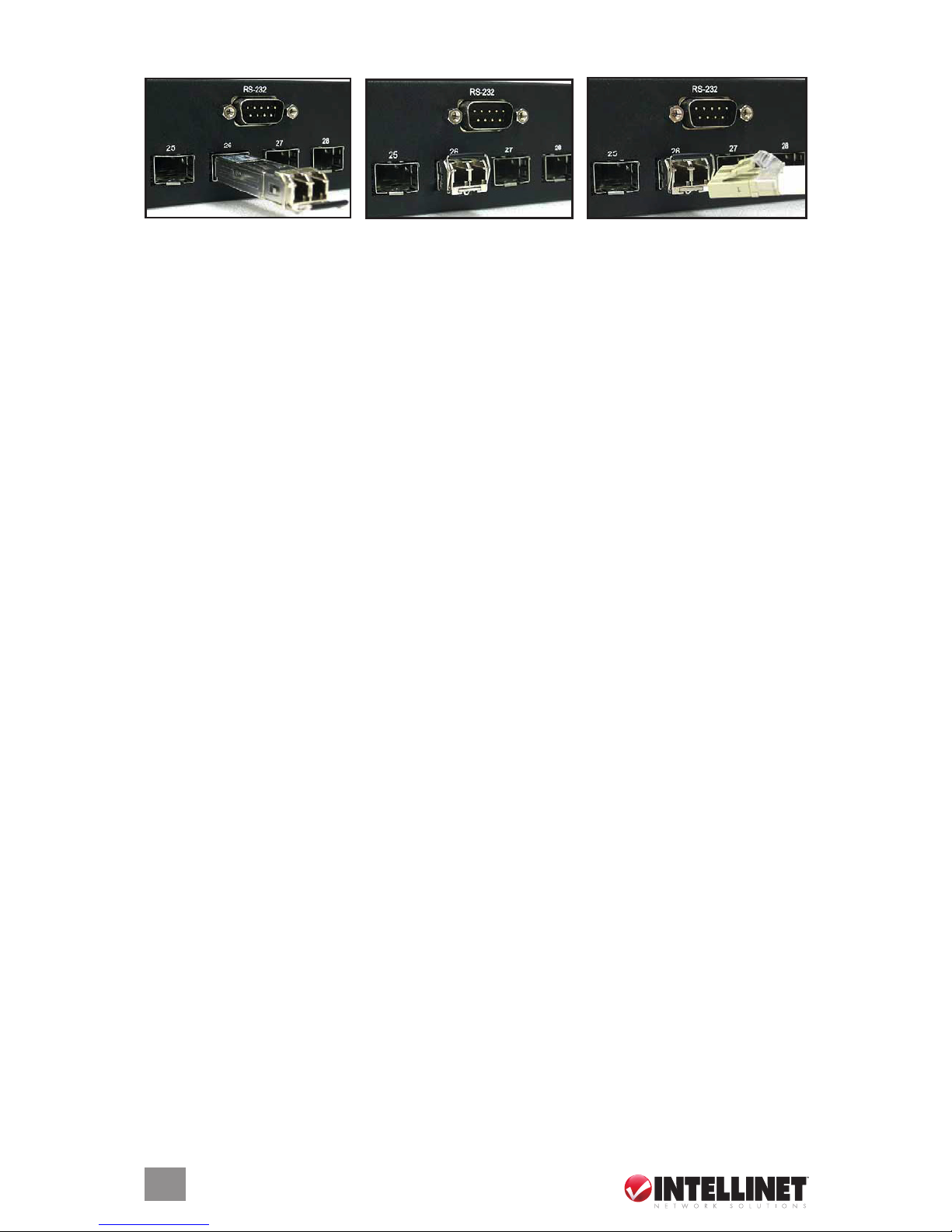
1.2.3 Installing the SFP Modules and Fiber Cable
1. Slide the selected SFP module into one of the four Gigabit SFP slots below the RS-232 port,
making sure the SFP module is aligned correctly with the inside of the slot.
2. Insert and slide the module into the SFP slot until it clicks into place, removing any rubber
plugs that may be present in the SFP module’s mouth.
3. Align the ber cable’s connector with the SFP module’s mouth and slide the connector in
until a click is heard. (To pull the connector out, rst push down the release clip on top of the
connector.) Check the corresponding port LED on the front panel to be sure the connection
is valid (see subsection 1.1.4).
TiP: To properly connect ber cabling, check that the ber terminators are clean. You can clean
the cable plugs by wiping them gently with a clean tissue or cotton ball moistened with a little
ethanol. Dirty ber terminators on ber optic cables will impair the quality of the light transmitted
through the cable and lead to degraded performance on the port.
1.2.4 Connecting Copper Cable
The 10/100Base-TX RJ-45 Ethernet port fully supports auto-sensing and auto negotiation.
1. Insert one end of a Category 3/4/5/5e twisted-pair cable into an available RJ-45 port on the
switch and the other end into the port of the network node.
2. Check the corresponding port LED on the front panel to ensure the connection is valid (see
subsection 1.1.4).
1.2.5 Connecting the Console Port Cable
The console port (DB-9) provides the out-of-band management facility.
1. Use null modem cable to connect the console port on the front panel of the switch to the
computer COM port.
2. Congure the HyperTerminal settings as explained in the next section(s).
1.2.6 Connecting to Computers or a LAN
Use Ethernet cable (either crossover or straight-through) to connect computers (or hubs or
other switches) directly to the Managed Layer 3 Access Switch ports. NOTE: Use a twistedpair Category 5 Ethernet cable to connect the 1000Base-T port; otherwise, the link speed
cannot reach 1 Gbps.
2 SWITCH MANAGEMENT/OPERATION
2.1 System Overview
This system can be managed three ways:
• Out-of-band through the console port on the front panel;
• In-band by using Telnet; or
• By using Web-based management — accessible through a Web browser— which allows you
to congure the switch, monitor the LED panel and display statistics graphically after a
successful installation.
8
SYSTEM OVERVIEW
2.1.1 Conguration Using the Console Port (RS-232)
Prior to accessing the switch’s onboard agent (software that supports SNMP — see subsection
2.1.3 below) via a network connection, rst congure the switch by giving it a valid IP address,
subnet mask and default gateway using an out-of-band connection or the BOOTP protocol.
After conguring the switch’s IP parameters, you can access the onboard conguration program
from anywhere in the attached network or via the Internet by using Telnet from any computer
attached to the network or by using a Web browser (Internet Explorer 4.0 or above or Netscape
Navigator 4.0 or above).
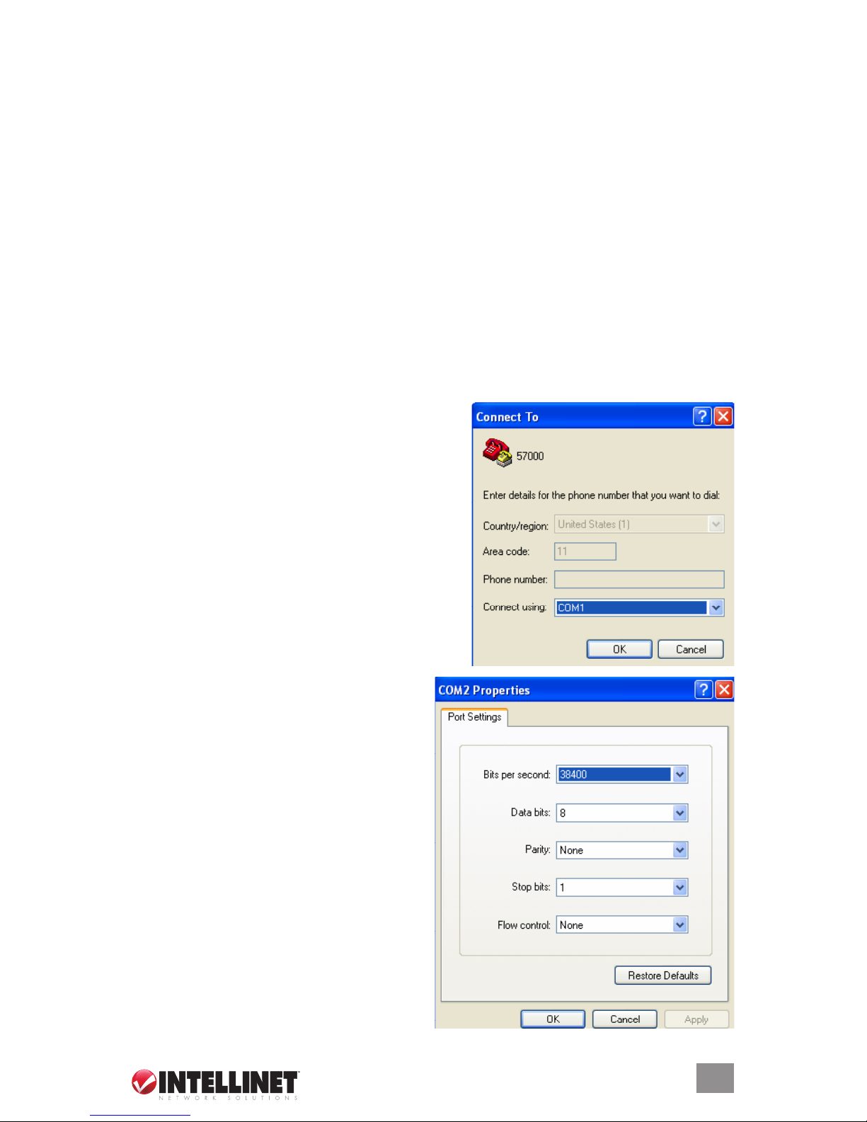
Access the switch via a terminal emulator (such as HyperTerminal) attached to the console port.
The console port is set at the factory with the following default COM port properties:
• Baud rate: 38,400
• Data size: 8 bits
• Parity: None
• Stop bits: 1
• Flow Control: None
NOTE: Congure your own terminal to match these settings; otherwise, the connection will not
work.
2.1.1.1 Using HyperTerminal to Set the IP Address
1. Verify that a console cable (RJ-45 to DB9 [for
the RS-232]) connection between the switch and
the workstation exists.
2. Launch the terminal emulation program on the
remote workstation and power on the switch.
Conrm that the correct COM port is selected.
3. Enter the correct parameters according to
the defaults presented above. Click “OK.”
9
SYSTEM OVERVIEW
3. The prompt screen will display. The default login is “admin,” with no preset password (just
press the “Enter” key).
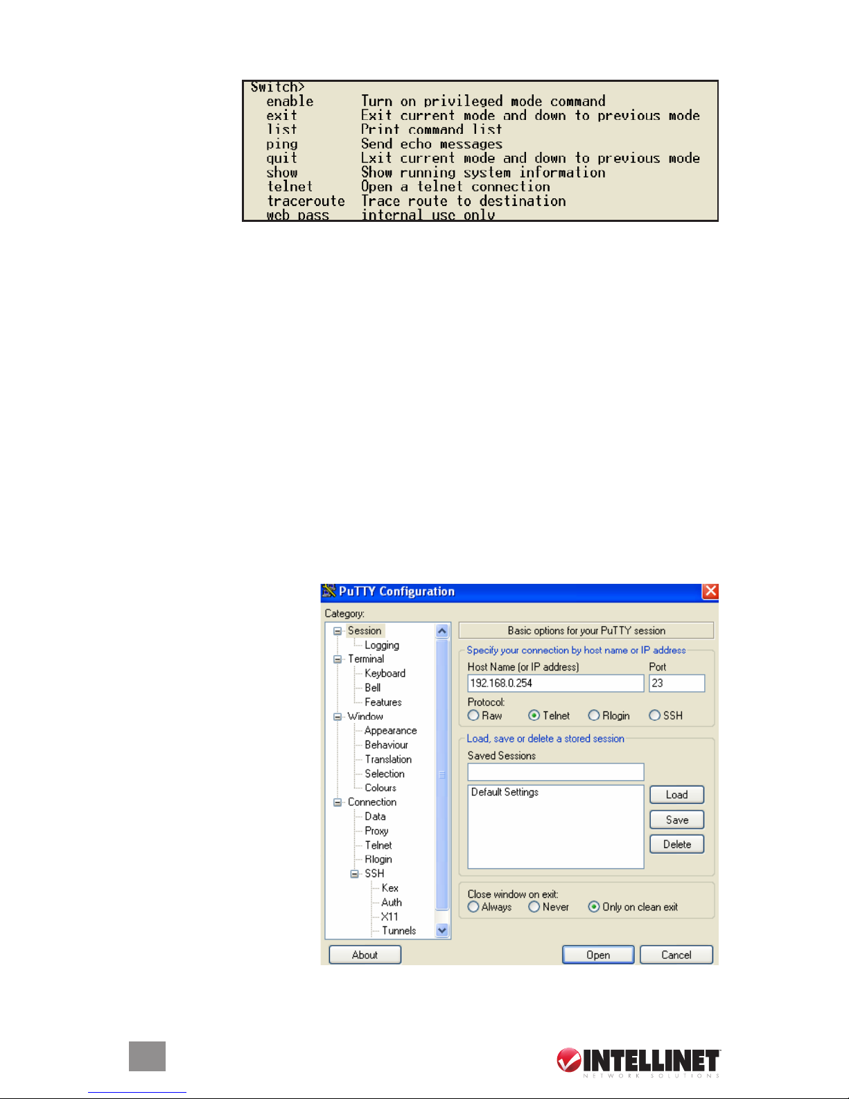
4. The prompt
Switch> will
display. For a
list of main
commands,
type “?” and
press “Enter.”
For a list of
subcommands, type a main command (such as “list”) and press “Enter.”
After a successful login, type the following command lines to change the device IP, network
mask and gateway address. The “xxx” segments represent values between 0 and 255. Be
sure to enter your IP address information in this form (including the periods separating the
segments), as the conguration program will not accept any other format.
• set eth0 ip xxx.xxx.xxx.xxx
• set eth0 netmask xxx.xxx.xxx.xxx
• set eth0 gateway xxx.xxx.xxx.xxx
Once the new information has been entered, the system will conrm whether the operation
is successful and restart automatically. Record the new address information and store it in
a secure location.
NOTE: With HyperTerminal, the command lines are the same as for Telnet: You can continue
using HyperTerminal along with the instructions given in the following sections. Otherwise, log
out by typing “exit” and pressing the “Enter” key. Then, you can congure the switch via an
HTTP Web browser or by using Telnet with menu-driven or command line interfaces.
NOTE: Remember that IP addresses are unique. If an address isn’t available, contact your
Internet service provider to obtain one.
2.1.2 Conguration Using Telnet and SSH
1. Activate your workstation’s
command prompt program
(such as PuTTY) and
access your switch via the
Internet by entering the
correct IP address. NOTE:
The factory default is
192.168.0.254: Connect
directly via the console
port to congure a unique
IP address. A command
prompt program such as
PuTTY will provide you
with the option of choosing
either Telnet or SSH
(Secure Shared). SSH is
an encrypted protocol
that’s ideal for ISP workers
who need to be extra
careful when managing
their switches.
2. Click “Open” to display a command prompt screen.
10
SYSTEM OVERVIEW
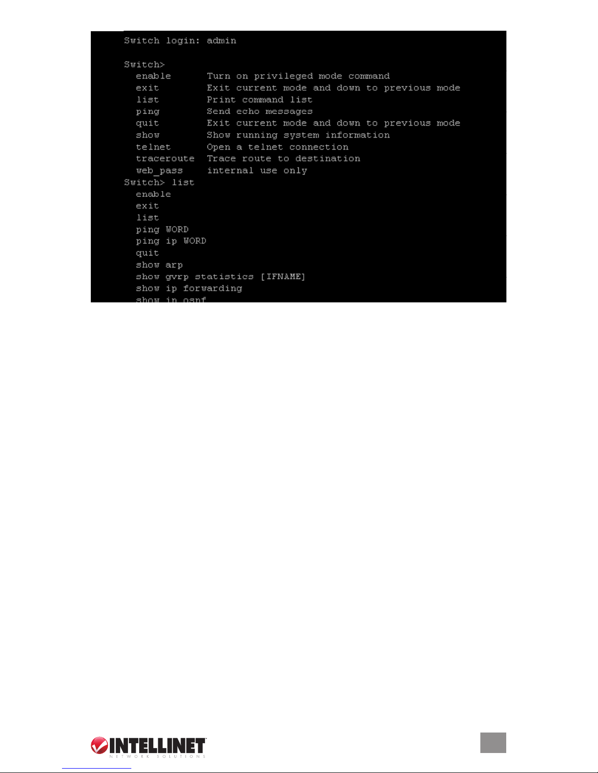
3. On the Switch login: line, type the pre-set password (the factory default is “admin”). Type
“?” and press the “Enter” key for a list of the main commands. As shown above, the “list”
command has been entered below the last main command listed.
2.1.3 SNMP-Based Management and Settings
You can manage the Managed Layer 3 Access Switch with SNMP Manager software (referred
to as an agent) that runs locally on the device. The SNMP agent decodes the incoming SNMP
messages and responds to requests with MIB (Management Information Base) objects that
are dened and stored in the database. The SNMP agent updates the MIB objects to generate
statistics and counters.
The Simple Network Management Protocol (SNMP) is an application layer specically designed
for managing and monitoring network devices. SNMP enables network management stations
to read and modify the settings of gateways, routers, switches and other network devices. Use
SNMP to congure system features for proper operation, to monitor performance and to detect
potential problems in the switch, switch group or network.
In short, SNMP denes both the format of the MIB specications and the protocol used to
access this information over the network.
2.1.3.1 MIB Objects
The Management Information Base (MIB) stores management and counter information. The
switch uses the standard MIB-II Management Information Base module, so, consequently,
values for MIB objects can be retrieved from any SNMP-based network management software.
MIB values can be either read-only or read-and-write.
2.1.3.2 Traps
Traps are messages that notify network personnel of events that occur on the switch. The events
can be as serious as a reboot (someone accidentally turns the switch off) or as minor as a port
status change. The switch generates traps and sends them to the trap recipient (or network
manager). Typical traps include trap messages for Authentication Failure, Topology Change
and Broadcast/Multicast Storm.
11
SYSTEM OVERVIEW

2.1.4 Initial Connection to the Switch
The switch supports user-based security that allows you to prevent unauthorized users from
accessing the switch or changing its settings. This feature requires Java Runtime Environment
(JRE) 5.0 Update 5, which, if not already on your computer, can be easily installed in as little
time as ve minutes by following these steps.
1. Open your network browser (you must be connected to the Internet) and enter the factory
default IP address of the switch (192.168.0.254) in the address bar. If a pop-up screen
appears and advises you to click on it to install, do so.
2. If the security warning shown
at right displays, click “Install.”
3. The initial Java Installer
screen will display. Wait a
few moments until the next
screen (License Agreement)
appears.
4. After reading the License
Agreement, select Typical
setup (the recommended
option vs. Custom setup). Click “Accept.”
5. If Internet Explorer is set as
the default browser on your
system, then the Java
Runtime Environment 5.0
Update 5 – Google Programs
dialog box will appear. By
default, Google Toolbar for
Internet Explorer is selected.
Click “Next” to begin installing
selected program features,
including the JRE, on your
system.
6. The Progress screen displays
to indicate installation status
once the process has begun.
(Depending on connection
speed, the process takes
between ve and 30 minutes.)
A few brief dialog boxes will
conrm the last steps of the
installation process, then a
concluding message will
appear with the conrmation
“Installation Completed OK.”
Click “Finish.”
12
SYSTEM OVERVIEW
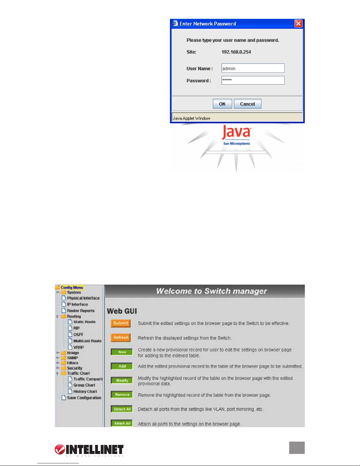
After completing the installation process,
the program will display the screen at right
every time you enter the IP address. The
default username and password are both
“admin.” Click “OK” to enter the switch’s
management interface.
NOTE: If you still have problems accessing
the hyperlink:
• Check the rewall in your PC or the
rewall that your company uses. This
rewall could be blocking access to the
hyperlink.
• Make sure you have downloaded the
latest version of Java Runtime
Environment. This software will run on
any of the normal Windows systems, as
well as on Unix.
2.2 Web Management
The Managed Layer 3 Access Switch provides Web pages that allow equipment management
through the Internet. The Java Runtime Environment (JRE) is required to run Java applet
programs that are automatically downloaded from the switch during management functions.
(See subsection 2.1.4 above.)
2.2.1 Login
1. Open your Web browser, enter the factory default IP address — http://192.168.0.254 — in
the Web address (location) box, then press “Enter.” The login screen shown above (subsection
2.1.4) is displayed.
2. Enter the default username and password (“admin” for both) the rst time you log in. These
can subsequently be changed (recommended for security purposes) through the CLI interface.
(See subsection 2.3.2.) Click “OK.”
3. The Welcome (home) screen will display each time you log in, presenting the Conguration
Menu (on the left side of the screen) and the following Web GUI options.
13
WEB MANAGEMENT
• Click “New” to create a new entry for editing to the table (temporary until “Submit” is clicked).
• Click “Add” to add the new entry to the table (temporary until “Submit” is clicked).
• Click “Modify” to save changes to an existing entry (temporary until “Submit” is clicked).
• Click “Remove” to remove a selected entry (temporary until “Submit” is clicked).
• Click “Attach All” to select all ports for a selected entry (temporary until “Submit” is clicked).
• Click “Detach All” to unselect all ports for a selected entry (temporary until “Submit” is clicked).
• Click “Submit” to save changes to the RAM memory of the switch.
• Click “Refresh” to display current settings of the switch for viewing the effect of changes.
WarNiNg: Clicking “Submit” only congures the switch hardware and saves the
settings to RAM memory. Such changes will be lost if the switch is powered off. To
save changes permanently in the switch’s Flash memory, click on “Save Conguration”
(listed at the bottom of the Conguration Menu). Once the “Save Conguration” screen displays,
click “Save” to store all congurations permanently in the Flash memory.
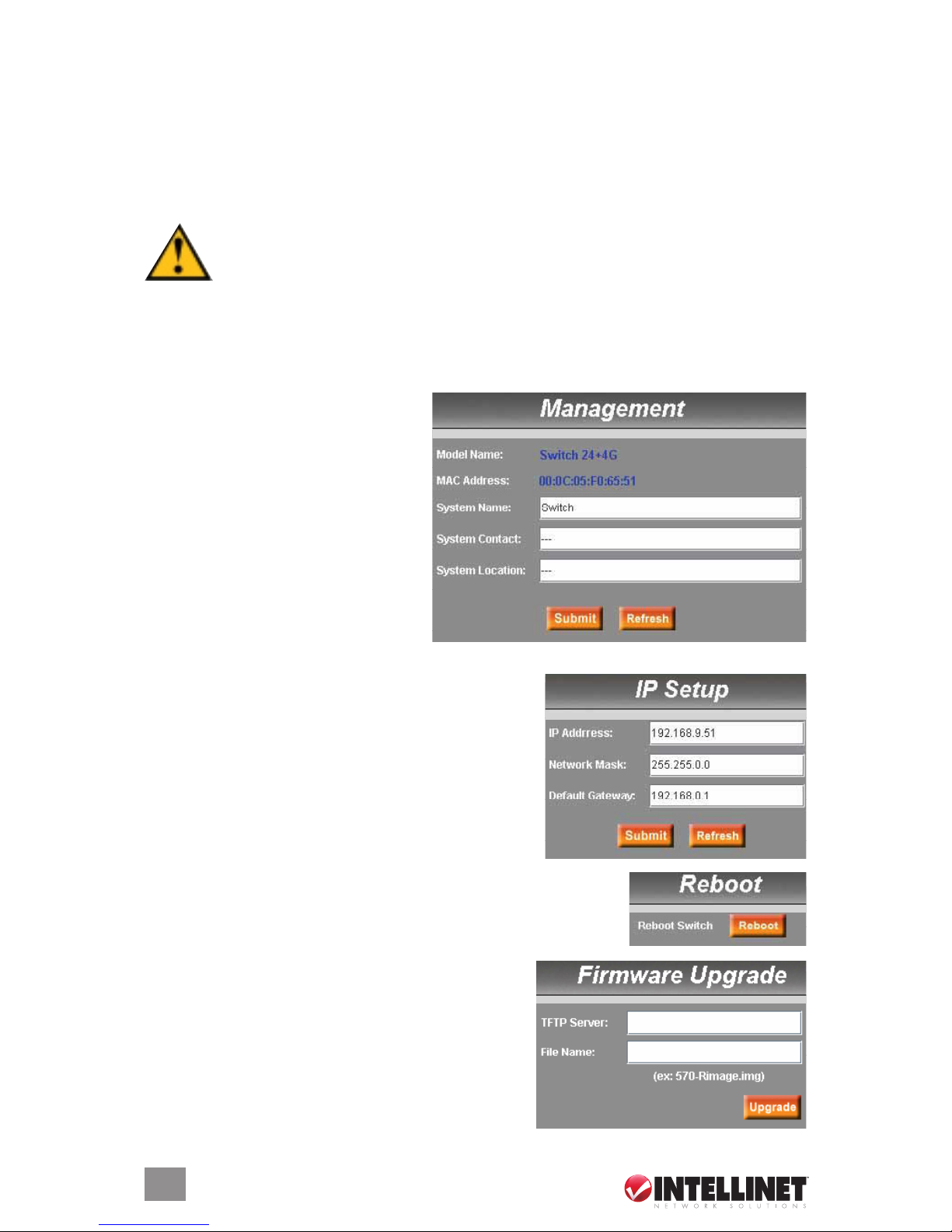
2.2.2 System
System on the Cong Menu presents Management, IP Setup, Reboot and Firmware Upgrade.
2.2.2.1 Management
Model Name: The product name is listed.
MAC Address: The switch’s MAC
address is listed.
System Name: The user-assigned name
to identify the system (editable).
System Contact: Enter info as desired.
System Location: Enter info as desired.
Click “Submit” to commit the settings.
Click “Refresh” to display current switch
settings. To eventually make all changes
permanent in Flash memory, click on
“Save Conguration” (listed at the bottom of the Conguration Menu) and click “Save.”
2.2.2.2 IP Setup
IP Address: This is the IP address for the switch.
Network Mask: This is the network mask for this network.
Default Gateway: This is the default gateway of the network.
Click “Submit” to commit the settings. Click “Refresh” to
display current switch settings. To eventually make all
changes permanent in Flash memory, click on “Save
Conguration” (listed at the bottom of the Conguration
Menu) and click “Save.”
2.2.2.3 Reboot
Clicking “Reboot” (rebooting the system) stops the network trafc and
terminates the Web interface connection.
2.2.2.4 Firmware Upgrade
Enter the TFTP server IP address and rmware lename
(e.g., enter “192.168.1.155” and “3112Single-v10.img”).
Click “Upgrade” to update the switch’s rmware from the
TFTP server. Click “Upload” to load the assigned
rmware to the switch, then reboot the system after a
successful rmware update. You’ll need to log in to the
Web interface again.
14
WEB MANAGEMENT
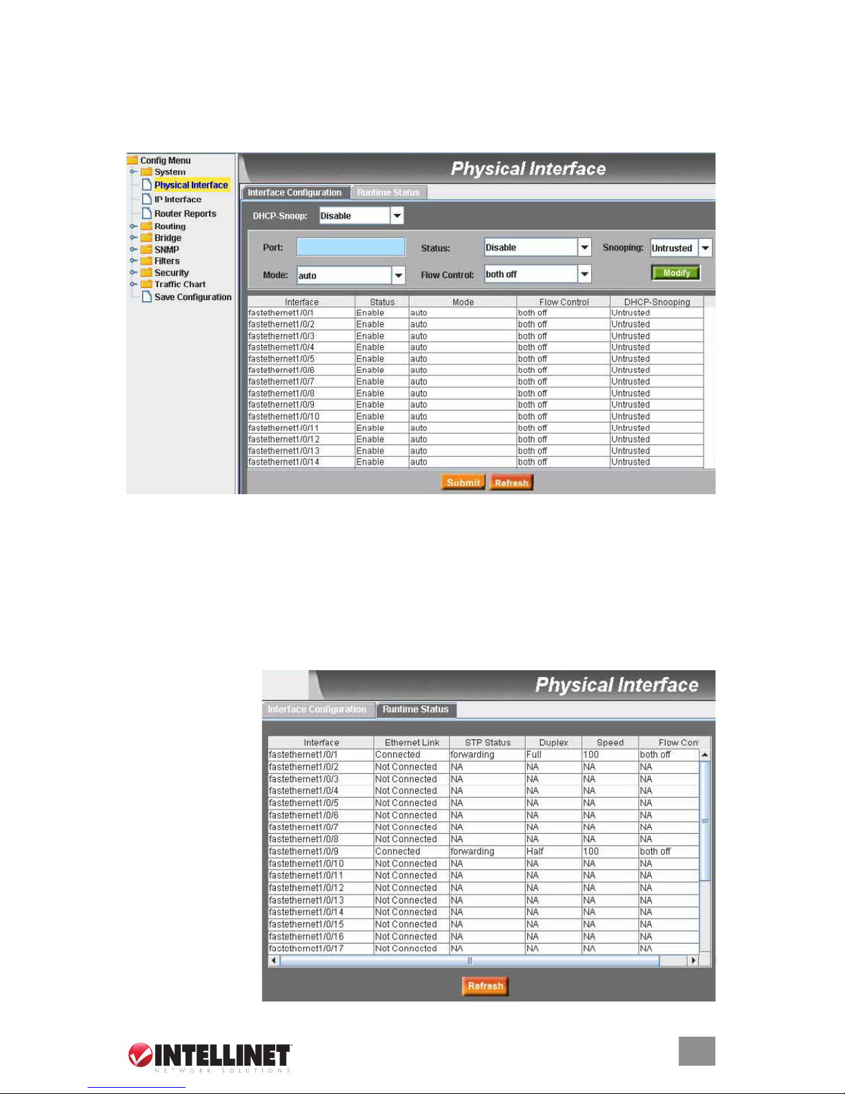
2.2.3 Physical Interface
Physical Interface on the Cong Menu displays Ethernet port status in real time. Two options
are available: Congure the port in the elds in the Interface Conguration window; and check
the results in the Runtime Status window.
2.2.3.1 Interface Conguration
Port: Select the port to congure.
Status: Enable/disable the port.
Mode: Set the speed and duplex mode.
Flow Control: Enable/disable the 802.3x ow control mechanism.
DHCP-Snoop: Enable/disable the DHCP snooping function.
Snooping: Assign the selected port to be an untrusted or trusted port.
Select the corresponding port number and congure the port setting, then click “Modify.” The
eld you change will update the content of the display window. However, the new settings do
not take effect until “Submit” is clicked.
2.2.3.2 Runtime
Status
Ethernet Link: The
link is connected
or not connected.
STP Status: STP is
enabled or disabled
on the port.
Duplex: Full duplex,
half duplex or NA.
Speed: This is the
link speed.
Flow Control: The
setting of the
802.3x ow control
mechanism on
both directions
of the port.
15
WEB MANAGEMENT

2.2.4 IP Interface
IP Interface on the Cong Menu allows users to see the Layer 3 interface status in real time
and congure the interface in the following elds.
Interface: Select the interface to be congured (vlan1 is used by the system).
IP: This is the interface IP address
Mask: This is the interface subnet mask.
MAC: This is the MAC address of this interface.
Status: This is the up/down status of this interface.
DHCP IP Helper Address: This is the IP address of your DHCP server.
Select the corresponding interface and congure the interface parameters, then click “Modify.”
The eld you changed will update the associated content in the display window. To save any
changes and make them effective immediately, click “Submit.” Click “Refresh” to refresh the display.
NOTE: There is one important thing to remember regarding DHCP and VLANs: Because each
VLAN is a separate IP subnet, you must congure your DHCP server to deliver IP addresses
that are appropriate for each subnet. With Windows 2000’s DHCP server, you do this by setting
up a separate DHCP realm for each VLAN. Not all DHCP servers have this capability. If your
existing DHCP server works only with at LANs, you’ll probably have to upgrade to a more
sophisticated package.
SPECiaL NOTE: It is strongly recommended that each interface have its own VLAN; i.e, one
VLAN should not be assigned for two interfaces. Otherwise, it will create confusion while RIP
is enabled. It is also recommended that only one physical port be assigned to the VLAN used
for the L3 interface. When assigning multiple ports to one L3 interface, the L3 trafc will always
go through the the port with lowest ID. The trafc load sharing is not supported in this case.
2.2.5 Router Reports
Router Reports on the Cong Menu displays the routing table of the switch.
16
WEB MANAGEMENT
Routing Protocol: This is the routing protocol type of the route. If it’s “connected,” the destination
is on the local LAN segment connected to the interface.
Destination: The destination IP address will be masked to generate an IP range as the objective
IP addresses of packets to be routed.
Mask: This is the mask for generating a range of IP addresses.
Connected via: This is the IP address of the next router for routing to another network.
Interface: This is the interface or VLAN ID from which the packets are routed outside.
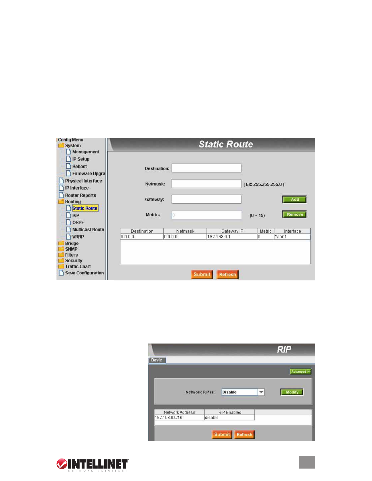
2.2.6 Routing
Routing on the Cong Menu presents Static Route, RIP, OSPF, Multicast Route and VRRP.
2.2.6.1 Static Route
This section is used to add a routing entry into the switch routing table. A routing entry added this
way will never be deleted by the system, hence the designation as “static.” The parameters below
must be input in order to congure a static route.
Destination: Enter the destination of the IP address.
Netmask: Enter the subnet mask of the destination for generating the IP range to be routed.
Gateway IP: Enter the gateway IP address of the next router the packets are to be sent to.
Metric: Enter a metric value (1-15). The lower the metric value, the more preferred the route.
Click “Add” after entering a new static route. The newly added entry displays in the list window.
Delete the selected route by clicking “Remove.” Routes that are added or removed will be stored
in the conguration le immediately.
2.2.6.2 RIP
This section is used to activate
the RIP routing protocol. When
RIP is turned on, the switch will
exchange routing information with
neighbor switches that are also
running RIP. Three subsections
present additional options: Basic,
Passive Interfaces and RIP
Version, the latter two being
accessible from the Basic screen,
as explained below.
17
WEB MANAGEMENT
 Loading...