

Intellinet 523769 User Manual
FAST
ETHERNET
MANAGED
SWITCH
USER
MANUAL
MODEL 523769
INT-523769-UM-0607-01


INTRODUCTION
Thank you for purchasing the INTELLINET NETWORK SOLUTIONS™ Fast Ethernet Managed
Switch, Model 523769.
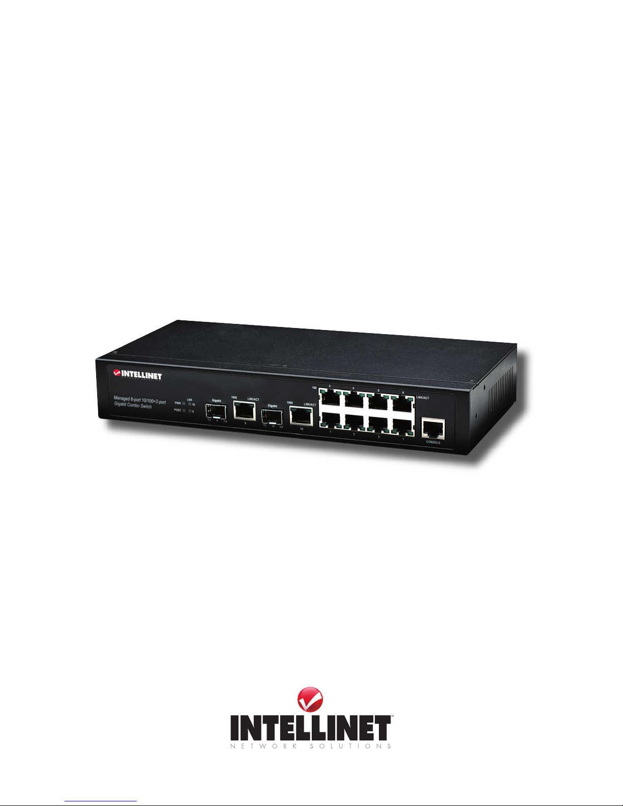
Equipped with eight 10/100Base-TX ports plus two combo 1000 Mb slots (ber options are
SFP-type and 1000Base-SX/LX/LHX), this device is designed with SNMP, RMON, exible
network management and monitoring options for increased efciency and performance.
Whether managing from an “in-band” SNMP management station or Internet Web browser, or
“out-of-band” on the RS-232 console port, this Fast Ethernet Managed Switch makes network
monitoring and troubleshooting easy.
With its Auto MDI/MDI-X and NWay capabilities — plus VLAN capabilities, Spanning Tree
Protocol, port isolation and the ability to add special software features upon request — it’s
simple to deploy within a network. Additionally, the slim housing design is ideal for installation
in locations with limited space and in applications requiring low port density. Once installed on
any premises, the switch immediately connects the premises via its combo Gigabit Ethernet
ports, which provide high-bandwidth uplinks over variable distances.
The easy-to-follow instructions in this user manual help make setup and operation quick and
simple, so you’ll also soon be enjoying the benets of these additional features:
• Store and forward switching architecture
• Full/half duplex operation
• IEEE 802.3x ow control for full duplex
• Packet ltering/forwarding rates of 1,488,000 pps (1000 Mbps), 148,800 pps (100 Mbps),
14,880 pps (10 Mbps)
• Port Mirroring support
• Broadcast storm control
• Support for jumbo frames (9 kBytes)
• Support for up to 8192 MAC address entries
• 180 kBytes buffer memory
• Lifetime Warranty
FCC WARNING
This equipment has been tested and found to comply with the limits for a Class A device,
pursuant to part 15 of FCC rules. These limits are designed to provide reasonable protection
against harmful interference in a commercial installation. This equipment generates, uses
and can radiate radio frequency energy and, if not installed and used in accordance with the
instructions, may cause harmful interference to radio communication. Operation of this
equipment in a residential area is likely to cause harmful interference, in which case the user
will be required to correct the interference at the user’s own expense.
CE
This is a Class A product. In a domestic environment, this product may cause radio
interference, in which case the user may be required to take adequate measures.
NOTE: Screen-shot images may have been modied to t the format of this manual.
3
INTRODUCTION

TABLE OF CONTENTS
Introduction ...................................................................................................... 3
1 HARDWARE .................................................................................................... 6
1.1 Front Panel ........................................................................................................ 6
1.2 Rear Panel ........................................................................................................ 6
1.3 Connectors ........................................................................................................ 6
1.3.1 10/100Base-TX Ports ........................................................................................ 6
1.3.2 10/100/1000Base-T Ports ................................................................................. 6
1.3.3 SFP Slots for SFP Modules .............................................................................. 7
2 INSTALLATION ................................................................................................ 7
2.1 Placement of the Device ................................................................................... 7
2.2 Connections and Indicators .............................................................................. 7
2.2.1 Power ................................................................................................................ 7
2.2.2 SFP Modules and Fiber Cable .......................................................................... 8
2.2.3 Connecting Copper Cable ................................................................................ 8
2.2.4 Connecting the Console Port Cable ................................................................. 8
2.2.5 Connecting to Computers or a LAN .................................................................. 8
2.2.6 Connecting the Power Adapter ......................................................................... 8
2.2.7 LED Indicators .................................................................................................. 9
3 ENHANCED FEATURES ................................................................................. 9
3.1 Jet Ring ............................................................................................................. 9
3.2 Xpress Ring .................................................................................................... 10
4 CONFIGURATION .......................................................................................... 10
4.1 CLI Management via the Console Port ........................................................... 10
4.1.1 Connecting a HyperTerminal............................................................................11
4.2 Menu-Driven User Interface via Telnet ............................................................12
4.2.1 System Information Menu ................................................................................12
4.2.2 DHCP Conguration Menu ..............................................................................13
4.2.3 Device Control Menu .......................................................................................13
4.2.3.1 Port Conguration ............................................................................................13
4.2.3.2 Bridge Menu .....................................................................................................14
4.2.3.3 VLAN Menu..................................................................................................... 16
4.2.3.4 Rate Control Conguration .............................................................................19
4.2.3.5 Port Mirror Conguration ................................................................................19
4.2.3.6 Trunk Conguration ........................................................................................ 20
4.2.3.7 IGMP Menu .................................................................................................... 20
4.2.3.8 MAC Conguration ......................................................................................... 20
4.2.3.9 Quality of Service (QoS) ................................................................................ 22
4.2.4 Management Setup Menu .............................................................................. 23
4.2.4.1 SNMP Conguration Menu ............................................................................ 23
4.2.4.2 Email Alarm Conguration ............................................................................. 24
4.2.4.3 Firmware Upgrade Menu ............................................................................... 24
4.2.4.4 User Conguration Menu ............................................................................... 25
4.2.4.5 Port Counter Menu ......................................................................................... 25
4.2.4.6 System Restart Menu .................................................................................... 25
4.3 Management via Internet Browser Interface .................................................. 25
4.3.1 System Details ............................................................................................... 25
4.3.1.1 System Information ........................................................................................ 26
4.3.1.2 Board Information .......................................................................................... 26
section page
4
CONTENTS

4.3.1.3 DHCP Conguration ...................................................................................... 26
4.3.2 Conguration .................................................................................................. 26
4.3.2.1 Port Conguration .......................................................................................... 26
4.3.2.2 Port Status ...................................................................................................... 27
4.3.3 Bridge Menu ................................................................................................... 27
4.3.3.1 Bridge Conguration (Enable/Disable STP, Jet Ring or Xpress Ring) .......... 28
4.3.3.2 STP System Conguration ............................................................................. 28
4.3.3.3 STP Per-Port Conguration ........................................................................... 29
4.3.3.4 Jet Ring Status ................................................................................................ 29
4.3.3.5 Xpress Ring Conguration .............................................................................. 29
4.3.4 VLAN Menu..................................................................................................... 30
4.3.4.1 VLAN Type (Conguration) ............................................................................. 30
4.3.4.2 Tag-Based Info .................................................................................................31
4.3.4.3 Management VLAN ....................................................................................... 32
4.3.5 Rate Control .................................................................................................... 32
4.3.6 Port Mirroring .................................................................................................. 33
4.3.7 Trunk Conguration ......................................................................................... 33
4.3.8 IGMP Menu ..................................................................................................... 34
4.3.8.1 IGMP Conguration ........................................................................................ 34
4.3.8.2 IGMP Groups Status ....................................................................................... 34
4.3.9 MAC Menu ...................................................................................................... 34
4.3.9.1 MAC Table Status ........................................................................................... 34
4.3.9.2 Lock MAC Address Learning ......................................................................... 35
4.3.9.3 Static MAC Conguration ............................................................................... 35
4.3.9.4 MAC Limit Conguration ................................................................................. 35
4.3.10 QoS Menu ....................................................................................................... 36
4.3.10.1 Base Conguration ......................................................................................... 36
4.3.10.2 Tag Priority ...................................................................................................... 36
4.3.10.3 IP ToS Priority ................................................................................................. 37
4.3.11 Management Conguration ............................................................................ 37
4.3.12 SNMP Conguration ....................................................................................... 37
4.3.12.1 SNMP Communities........................................................................................ 37
4.3.12.2 IP Trap Manager ............................................................................................. 37
4.3.13 Email Alarm Conguration .............................................................................. 38
4.3.14 User Conguration .......................................................................................... 38
4.3.15 Firmware Download (Upgrade System) .......................................................... 39
4.3.16 Conrmation File (System Backup) ................................................................ 39
4.3.17 System Restart Menu (Restart Option)........................................................... 39
4.4 CLI via the Console Port (Basic Instructions) ................................................. 40
4.4.1 Help Commands ............................................................................................. 40
4.4.2 Show Commands ............................................................................................ 40
4.4.3 System Congurations .....................................................................................41
4.4.3.1 Switch Congurations ..................................................................................... 42
4.4.3.2 Port Congurations ......................................................................................... 42
4.4.3.3 Spanning Tree Protocol (STP) Congurations ................................................ 42
4.4.3.4 Virtual LAN (VLAN) Congurations ................................................................ 43
4.4.4 SNMP Congurations Using CLI .................................................................... 43
4.4.4.1 SNMP Congurations ..................................................................................... 43
4.4.4.2 Set SNMP Traps ............................................................................................. 43
4.4.4.3 Set Email ......................................................................................................... 44
5 TROUBLESHOOTING ................................................................................... 44
6 SPECIFICATIONS .......................................................................................... 45
5
CONTENTS
6
HARDWARE
1 HARDWARE
The Fast Ethernet Managed Switch was developed with a host of features — including both
Xpress Ring and Jet Ring — that makes it particularly well-suited for SOHO applications that
demand the utmost in reliability. The Jet Ring offers a recovery time of less than 300 ms in
case of any network-link failure; the Xpress Ring can recover from such a failure within 50 ms.
The device comes with eight copper ports (10/100) and two Gigabit combo ports (2 SFP ber
slots and two copper ports – 1000 Mbps) that provide 10/100/1000Base ber-to-copper
conversion, helping ensure “always-on” connectivity and eliminating costly network downtime.
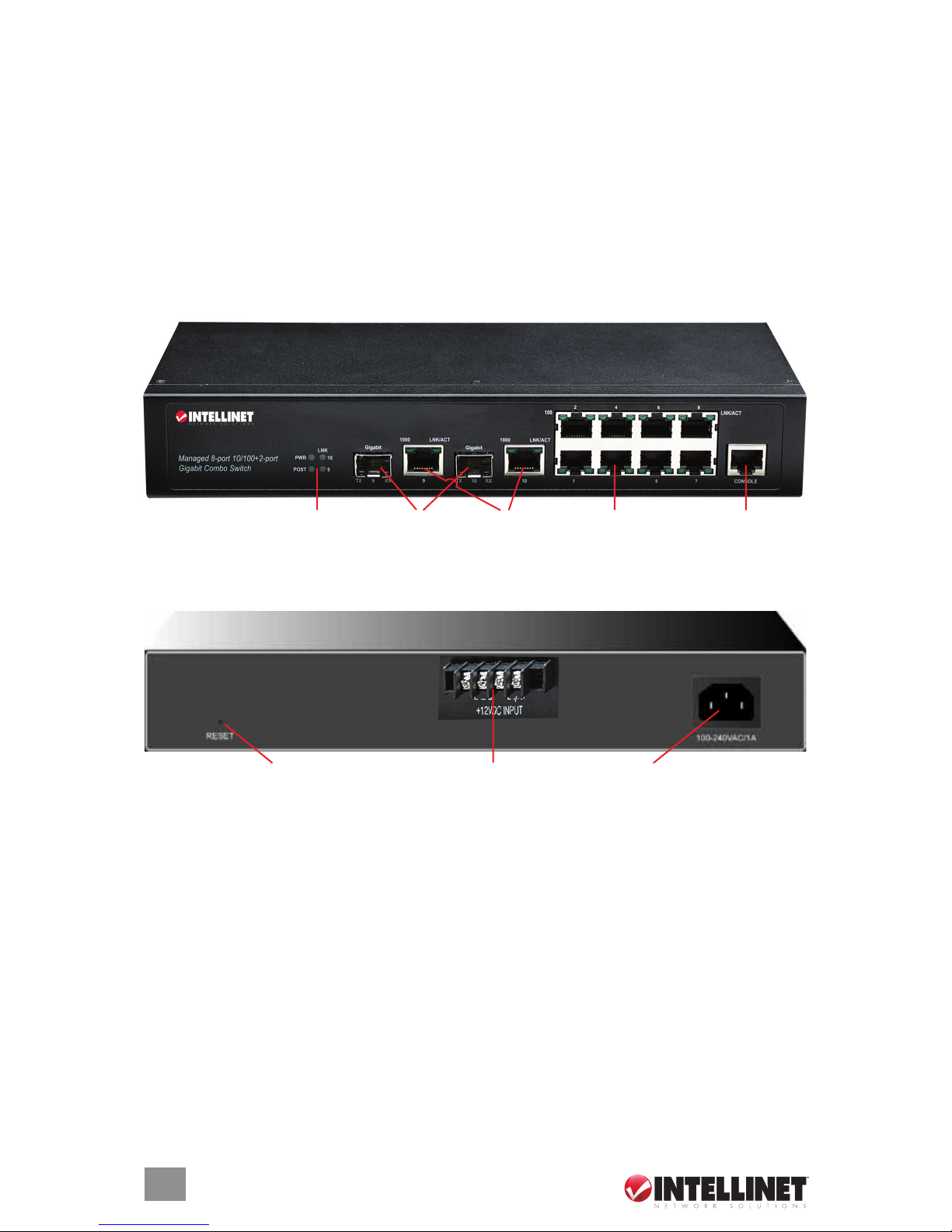
1.1 Front Panel
1.2 Rear Panel
1.3 Connectors
The switch utilizes ports with copper and SFP ber port connectors functioning under Ethernet/
Fast Ethernet/Gigabit Ethernet standards.
1.3.1 10/100Base-TX Ports
The 10/100Base-TX ports support network speeds of either 10 Mbps or 100 Mbps, and can
operate in half and full duplex transfer modes. These ports also offer automatic MDI/MDI-X
crossover detection that gives true Plug and Play capability: Just plug the network cables into
the ports and the ports will adjust according to the end-node devices. NOTE: Cat3 or better
cable is recommended for the 10 Mbps ports; Cat5 or better for the 100 Mbps ports.
1.3.2 10/100/1000Base-T Ports
The switch has two Gigabit 10/100/1000Base-T ports for RJ-45 connectors that have the
same features as the above-mentioned 10/100 ports. The only difference is that the Gigabit
Unit LEDs
SFP slots Gigabit
Ethernet ports
Copper ports Console port
Power socketReset button
DC power connections

copper ports support network speeds of 10/100/1000 Mbps.
These two ports are located next to their corresponding SFP-type ber slots, and each of these
RJ-45 ports is interchangeable with its corresponding SFP slot. The Gigabit copper port will
have the same number as its corresponding SFP slot. Once an SFP ber slot is connected, the
correspondingly numbered RJ-45 port won’t function.
1.3.3 SFP Slots for SFP Modules
The two SFP slots are designed to house Gigabit SFP modules that support network speeds
of 1000 Mbps. These slots are interchangeable with the two 1000Base-T ports, and the slots
have the same port numbers as their corresponding 1000Base-T ports. Once an SFP slot is
connected via an SFP module, the correspondingly numbered 1000Base-T port won’t function.
2 INSTALLATION
The location of the switch can greatly affect its performance. Follow these recommendations:
• Install the switch in an appropriate place based on the Specications (Section 12) for the
acceptable temperature and humidity ranges.
• Install the switch in a location that isn’t affected by strong electromagnetic eld generators
(such as motors), vibration, dust and direct sunlight.
• Leave at least 10 cm of space at the front and rear of the unit for ventilation.
• Afx the provided rubber pads to the bottom of the switch to protect the case.
2.1 Placement of the Device
For horizontal (desktop, shelf, etc.) installation of the switch, follow these steps.
1. Place the switch on a clean, at and safe surface that has convenient access to AC power.
2. Separate the four self-adhesive rubber pads and attach them to the switch’s underside.
3. Connect the switch to an AC power source. (The green PWR LED on the front panel should
light up.)
4. Connect the cables from the network partner devices to the ports on the front panel. (The
green LNK LED on the front panel associated with the port should light.)
For vertical (wall, post, etc.) installation of the switch, simply use the underside of the unit as a
template to measure and mark the position of the holes on to the surface where the unit is to
be installed. Then use the two screws provided to mount the switch rmly in place.
WARNING: Because invisible laser radiation may be emitted from the aperture of a
port when no cable is connected, avoid exposure to laser radiation and do not stare
into open apertures.
For rackmounting of the switch, attach brackets to each side of the switch and place the
brackets in the rack’s slots. Insert and tighten two screws to securely attach the bracket to the
rack on each side.
2.2 Connections & Indicators
The switch can be used to connect up to 10 network devices by employing a combination of
twisted-pair and ber cabling paths at Ethernet, Fast Ethernet or Gigabit Ethernet speeds.
2.2.1 Power
The switch uses a DC power supply of 9 – 48 V DC. The power and redundant power
7
INSTALLATION

connection is provided via a terminal block located at the top of the switch. The switch’s power
supply automatically self-adjusts to the local power source and may be powered on without
having any or all LAN segment cables connected. Check the front-panel as the device is turned
on to verify that the PWR LED lights. If it doesn’t, check that the power cable is correctly and
securely plugged in. If a redundant power supply is connected, an RPS LED will light
2.2.2 SFP Modules and Fiber Cable
To connect to either of the SFP (small form factor pluggable) slots:
1. Making sure it’s aligned properly, slide the SFP module (Fig. 2) into the selected SFP slot
(Fig. 1) until it clicks in place (Fig. 3).
2. Remove any rubber plugs from the mouth of the module.
3. Making sure it’s aligned properly, slide the ber cable connector (Fig. 4) into the SFP
module until it clicks in place (Fig. 5).
4. Check the corresponding port LED on the front panel to be sure the connection is valid.
(See 2.2.7 LED Indicators, Page 9.)
5. To remove a connector from a module, squeeze the release clip on the connector’s top.
NOTE: Check that the ber terminators are clean. As needed, wipe them gently with a clean
tissue or cotton ball lightly moistened with ethanol. Dirty ber terminators on ber optic cables
will impair the quality of the light transmitted through the cable, leading to degraded performance
on the port.
2.2.3 Connecting Copper Cable
The 10/100/1000Base-T RJ-45 Ethernet ports fully support auto-sensing and auto-negotiation.
1. Insert one end of a Category 3/4/5/5e twisted pair cable (see 1.3.1 NOTE, Page 6) into an
available RJ-45 port on the switch and the other end into the port of the network node.
2. Check the corresponding port LED on the front panel to be sure the connection is valid.
(See 2.2.7 LED Indicators, Page 9.)
2.2.4 Connecting the Console Port Cable
The console port (DB-9) serves the out-of-band management facility.
1. Use null modem cable to connect the console port on the switch to the computer’s COM port.
2. Insert the RJ-45 end of the (8-pin RJ-45 to DB-9) cable into the RJ-45 console port on the
switch and the other end into the computer’s COM port. For console port (8-pin RJ-45) pin
assignment, see Appendix A.
3. Congure the HyperTerminal settings. (See Section 4.1, Management via Console Port.)
2.2.5 Connecting to Computers or a LAN
Use either crossover or straight-through Ethernet cable to connect computers, hubs or other
switches directly to the switch ports. NOTE: Use a twisted pair Category 5 Ethernet cable to
connect the 1000Base-T port; otherwise, the link speed cannot reach 1 Gbps.
2.2.6 Connecting the Power Adapter
Connect the AC power cord to the power receptacle on the back of the switch and plug the
other end into a wall outlet or power strip. Check that the front-panel LEDs light up (as described
below) to indicate that the switch’s hardware is working properly.
Fig. 1 Fig. 2 Fig. 3 Fig. 4 Fig. 5
8
INSTALLATION
2.2.7 LED Indicators
This switch is equipped with unit LEDs (indicating the status of the switch) and port LEDs
(positioned alongside each copper port and indicating the status of the connections). All LEDs
light green.
LED Condition Status
PWR On Switch is being fed primary power.
Off Primary power is off or a failure has occurred.
POST Flashing POST function upon startup.
On POST function successfully performed.
100 (copper ports 1-8) On Port is operating at 100 Mbps.
Off Port is operating below 100 Mbps.
1000 (copper ports 9-10) On Port is operating at 1000 Mbps.
Off Port is operating below 1000 Mbps.
LNK/ACT (copper ports 1-10) On Port is connected with a compliant device.
Flashing Data trafc is passing through the port.
Off No valid link has been established at the port.
LNK (SFP ports 9-10) On Port is connected with a compliant device.
Off No valid link has been established at the port.
NOTE: The ber module does not support half duplex mode.
3 ENHANCED FEATURES
3.1 Jet Ring
Setting up Jet Ring (redundant linking) on your network helps protect critical links against
failure and network loops, and reduces network downtime to less than 300 ms. It allows users
to set up a redundant path in the network to provide a backup data transmission route in the
event that a connection is abruptly disconnected or damaged. This is an extremely important
feature in many applications because a link failure in a link with no backup can result in several
minutes of network downtime, possibly causing heavy losses.
Jet Ring automatically identies one switch as the “master” of the network, then automatically
blocks ports to prevent packets from traveling through any of the network’s redundant loop
segments. If one segment of this ring becomes disconnected from the rest of the network
because of a link failure, the Jet Ring protocol automatically re-adjusts the ring so that the
part of the network that was disconnected re-establishes contact with the rest of the network.
You can apply the ring
as in the diagram by
connecting four
switches. Jet Ring
then automatically
selects the “arbiter”
switch, and the
network is ready.
9
ENHANCED FEATURES
Jet Ring
bpdu
packet s
bpdu pac ket s
bpdu pac ket s
bpdu
packet s
MASTER
MASTER
2
2
4
4
3
3

3.2 Xpress Ring
Xpress Ring enables networks to recover from link failure within 50 ms. Unlike Jet Ring, however,
it needs some network conguration efforts. The user must assign two ring ports for each switch
in the ring. The user must also assign the “arbiter” switch, which will decide if it is necessary
to activate the backup path. For Xpress Ring, any switch can be the arbiter – just remember
that the arbiter switch must be part of the ring. In addition to rerouting the transmission within
50 ms, the arbiter switch will issue an alarm when a link failure occurs. The user will then be
informed of the failure and will be able to x the problem and recongure if required.
4 CONFIGURATION
For advanced management capabilities, the onboard management agent provides CLI
(command line interface) and menu-driven interface conguration programs. These programs
can be accessed by a direct or modem connection to the console port on the front panel (outof-band), or by a Telnet connection over the network (in-band).
The management agent is based on SNMP (Simple Network Management Protocol). This
SNMP agent permits the switch to be managed from any PC in the network by using in-band
management software. The management agent also includes an embedded HTTP Web agent
that can be accessed using a standard Web browser from any network computer.
This switch gives you exibility to access and manage it using any or all three of the methods below:
• CLI via the console port to initially set IP parameters (with added details in Section 4.4);
• Menu-driven congurations via Telnet;
• Internet browser interface
The administration console and Web browser interfaces are embedded in the switch software
and can be used immediately after setup.
4.1 CLI Management via the Console Port
Prior to accessing the switch’s onboard agent via a network connection, congure it with a
valid IP address, subnet mask and default gateway using an out-of-band connection or the
BOOTP protocol. After conguring the switch’s IP parameters, you can access the onboard
conguration program from anywhere within the attached network or via the Internet.
The onboard conguration program can be accessed using Telnet from any computer attached
to the network. It can also be managed from any computer using a Web browser (Internet
Explorer 4.0 or above, or Netscape Navigator 4.0 or above).
Access the switch via a terminal emulator (such as HyperTerminal) attached to the console
port. The console port is set at the factory with the following default COM port properties.
Congure your own terminal to match:
• Baud rate: 38,400
• Data size: 8 bits
• Parity: None
• Stop bits: 1
• Flow control: None
NOTE: Ensure that the terminal or PC you are using to make this connection is congured to
match the above settings; otherwise, the connection will not work. A console port cable is
provided with the switch to connect the PC’s COM port with the switch’s serial console (RJ-45)
port. (See Appendix A in Specications if necessary for cable pin assignment details.)
10
CONFIGURATION
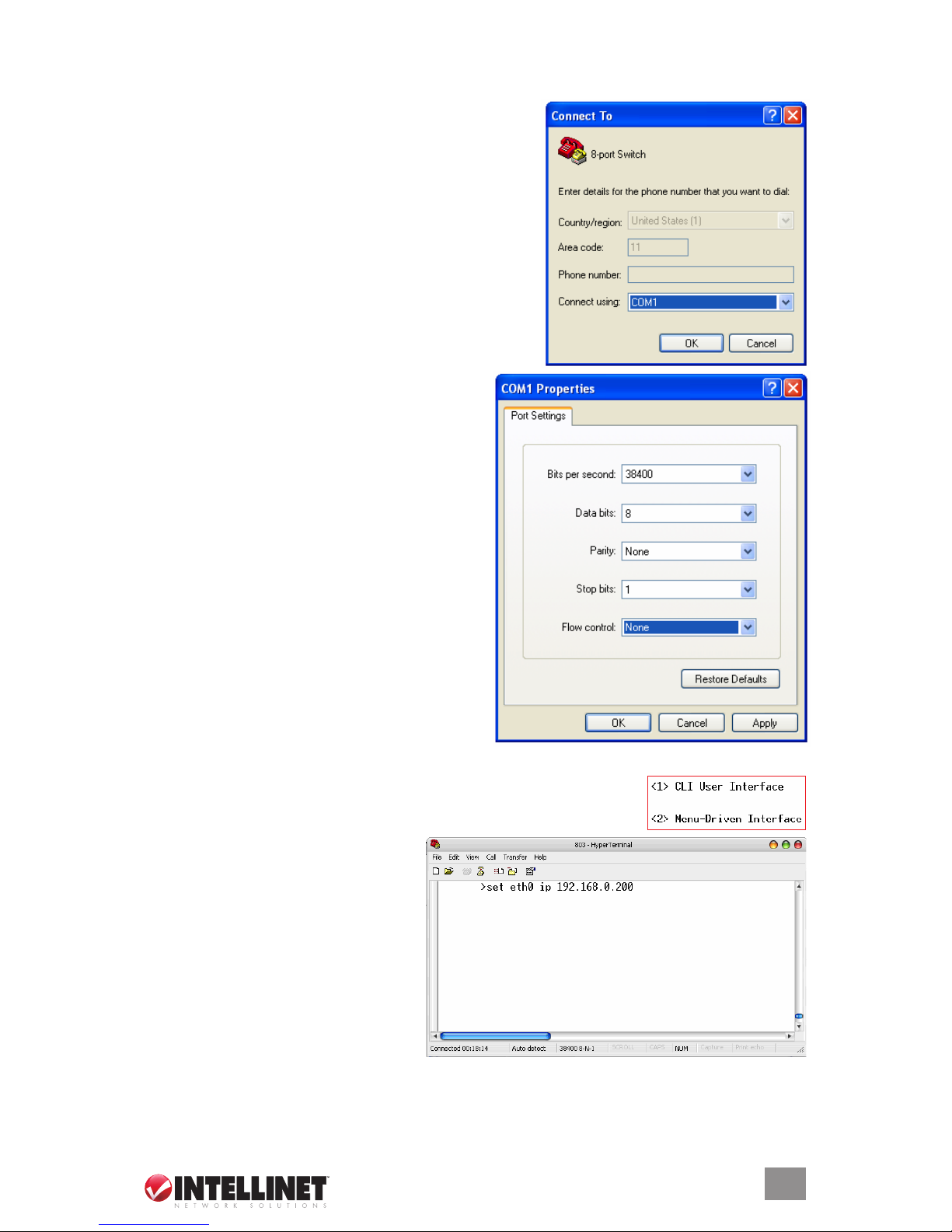
4.1.1 Connecting via HyperTerminal
1. Verify the console cable (RJ-45 to DB9) connection between the switch and workstation.
2. Launch the terminal emulation program on the remote
workstation and turn on the switch. Be sure to select
the correct COM port. Click “OK.”
3. Enter the proper parameters based on the
defaults listed above. Click “OK.”
4. A start screen appears. Press the “Enter” key to advance to HyperTerminal’s login screen.
5. The program presents both CLI and menu-driven user interfaces via
console or Telnet. After logging in to the system, the prompt at right
displays. Enter “1” to select the “CLI User Interface” operation.
6. Enter the commands below to reset
the IP address, subnet mask and
gateway. (Each “xxx” represents a
value between 0 and 255, as shown
at right.) NOTE: Be sure to separate
each 1- to 3-digit segment with a
period, as the program won’t accept
anything other than this format:
• set eth0 ip xxx.xxx.xxx.xxx
• set eth0 netmask xxx.xxx.xxx.xxx
• set eth0 gateway xxx.xxx.xxx.xxx
Once the new information has been entered, the system will conrm the success of the
operation (as shown at right) and then restart automatically. Remember to record the new IP
address and keep it in a secure location.
11
CONFIGURATION

With HyperTerminal, command lines are
the same as those for Telnet. You can
continue to use HyperTerminal with the
instructions provided. Otherwise, log
out by entering “exit” and pressing the
“Enter” key. The switch can then be
congured via an HTTP Web browser
or Telnet with menu-driven or command
line interfaces.
4.2 Menu-Driven User Interface via Telnet
1. Open a command-prompt window and enter the following command line, in which the “xxx”
segments represent the IP address: telnet xxx.xxx.xxx.xxx. (Examples like 192.168.0.200
are used throughout this manual.) Press the “Enter” key to advance to the next screen.
NOTE: The default login is “admin,” with no preset password.
2. The program presents both CLI and menu-driven interfaces
via console or Telnet. Select “Menu-Driven Interface.”
3. The Main Menu screen displays. Press the “Tab” key to move
through and highlight options; press the “Enter” key to select/
unselect or receive a text prompt (or to exit from sub-menus);
press the “Esc(ape)” key to return to the main menu. Save
after editing; unsaved entries will return to default values or
the most recent saved values.
System Information: Default system information, such as IP
Address, Subnet Mask and Gateway.
DHCP Conguration: Disable DHCP Client or enable it to set
and display DHCP Leased Time and DHCP Expiry Time.
Device Control: Conguration options (Port, Bridge, VLAN Rate Control, Trunks, etc.)
Management Setup: Conguration options for SNMP, Email Alarm, Firmware Upgrade and User.
Port Counter: Ports statistics, such as packet and collision totals.
System Restart: Options for restarting through software and/or restoring factory default settings.
4.2.1 System Information Menu
This menu screen presents a number of
switch features and the status of specic
switch parameters, as shown at right. Also
displayed is the IP address of the switch;
the subnet mask, which identies the
host-address bits used for routing to
specic subnets; and the gateway, which
passes trap messages from the system’s
agent to the management station — each
of which can be changed as needed or
required. NOTE: Sample addresses may
be presented that don’t represent factory
defaults or the required addresses.
12
CONFIGURATION
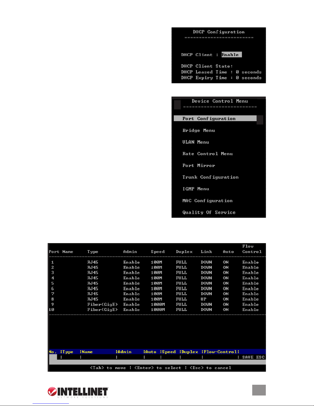
4.2.2 DHCP Conguration Menu
This screen presents the option of either disabling
or enabling DHCP Client. When enabled, DHCP
Leased Time and DHCP Expiry Time are displayed
in seconds, as shown.
4.2.3 Device Control Menu
Port Conguration: Congure various parameters for
each of the switch’s ports.
Bridge: Congure bridge settings, including those
of Jet Ring and Xpress Ring.
VLAN: Congure port- or tag-based VLANs.
Rate Control: Dene bandwidth/data rate control and
Jumbo Packet limits for each port.
Port Mirror: Select a port for mirroring to monitor
trafc.
Trunk Conguration: Congure up to four trunk groups.
IGMP Menu: Congure IGMP (Internet Group
Management Protocol) snooping and query, and
check group status.
MAC Conguration: Check MAC Table status, lock
MAC Address Learning and congure Static Unicast
MAC and MAC Limit.
Quality of Service: Set the QoS base conguration and the tag priority and IP ToS tables.
4.2.3.1 Port Conguration
13
CONFIGURATION
Port No.: In the settings panel at the bottom of the screen, use the “Enter” and “Tab” keys to
position the cursor in the desired eld and enter whichever port number you want to congure.
Name: The name assigned to a port for keeping records of the connections.
Type: The type of a port connector (ber or RJ-45).
Admin: Enable or disable the admin congurations.
Auto: Enable or disable the Auto-negotiation on the copper ports.
Speed: Presents the speed of ports in operation. You can also set the speed (10 – 100 Mbps) for
the RJ-45 ports.
Duplex: Presents the duplex status. You can also select the duplex mode (half or full).
Link: Presents the link status of a port.
Flow Control: Enable or disable the RJ-45 ports.
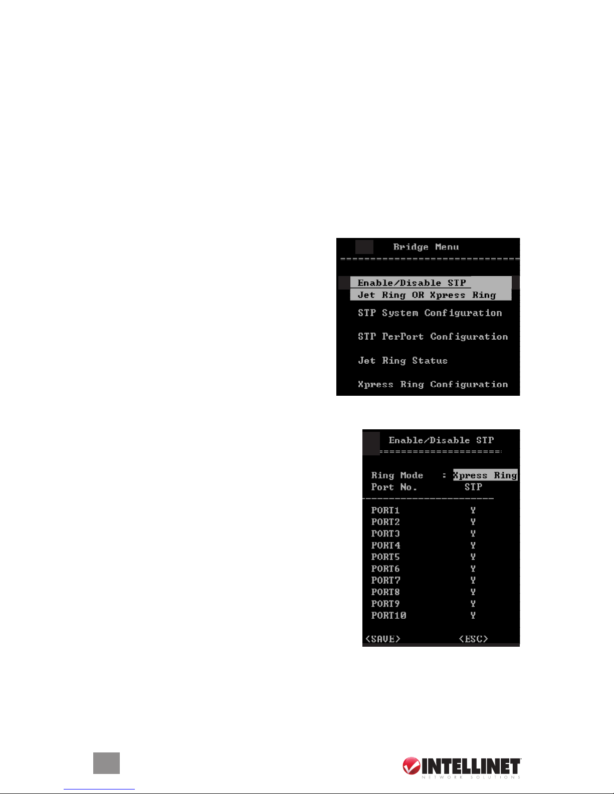
4.2.3.2 Bridge Menu
This menu is used to enable/disable STP (Spanning
Tree Protocol Algorithm), Jet Ring or Xpress Ring,
and to congure the STP settings if STP is enabled.
If Jet Ring is enabled, it offers a fast recovery time of
less than 300 ms in case a node goes down in the
ring. Xpress Ring offers a very fast recovery time of
less than 50 ms. The Spanning Tree algorithm is
used for detecting and disabling network loops, and
for providing backup links between switches, bridges
and routers. This allows the switch to communicate
and interact with other bridging devices (that is,
STA-compliant devices) in a network to ensure that
only one route exists between any two stations, and to provide redundant or backup links that
automatically take over when a primary link fails.
4.2.3.2.1 EnablE/DisablE sTP, JET Ring oR XPREss Ring
Choose an option — by scrolling with the space bar, by
selecting with the “Enter” key and by canceling with the
“Esc(ape)” key — and then set its parameters based on
network needs. The default setting is “Disabled.”
Press the “Tab” key to move through and highlight options;
press the “Enter” key to select/unselect or to exit a eld;
press the “Esc(ape)” key to return to the main menu. Save
after editing; unsaved congurations will return to default
values or the most recent saved values.
Ports 1 – 8 STP: When enabled (Y), the port participates in
the STP algorithm execution of the switch when 802.D is
selected. When disabled (–), the port does not participate.
4.2.3.2.2 sysTEm ConfiguR aTion
Use this option to congure the STP parameters. Before moving to this menu, however, make
sure the “802.1D” mode is selected when enabling or disabling (Enable/Disable) the STP, Jet
Ring or Xpress Ring modes. Otherwise, the values can’t be congured. On the left side of the
window, the root bridge information is displayed.
14
CONFIGURATION
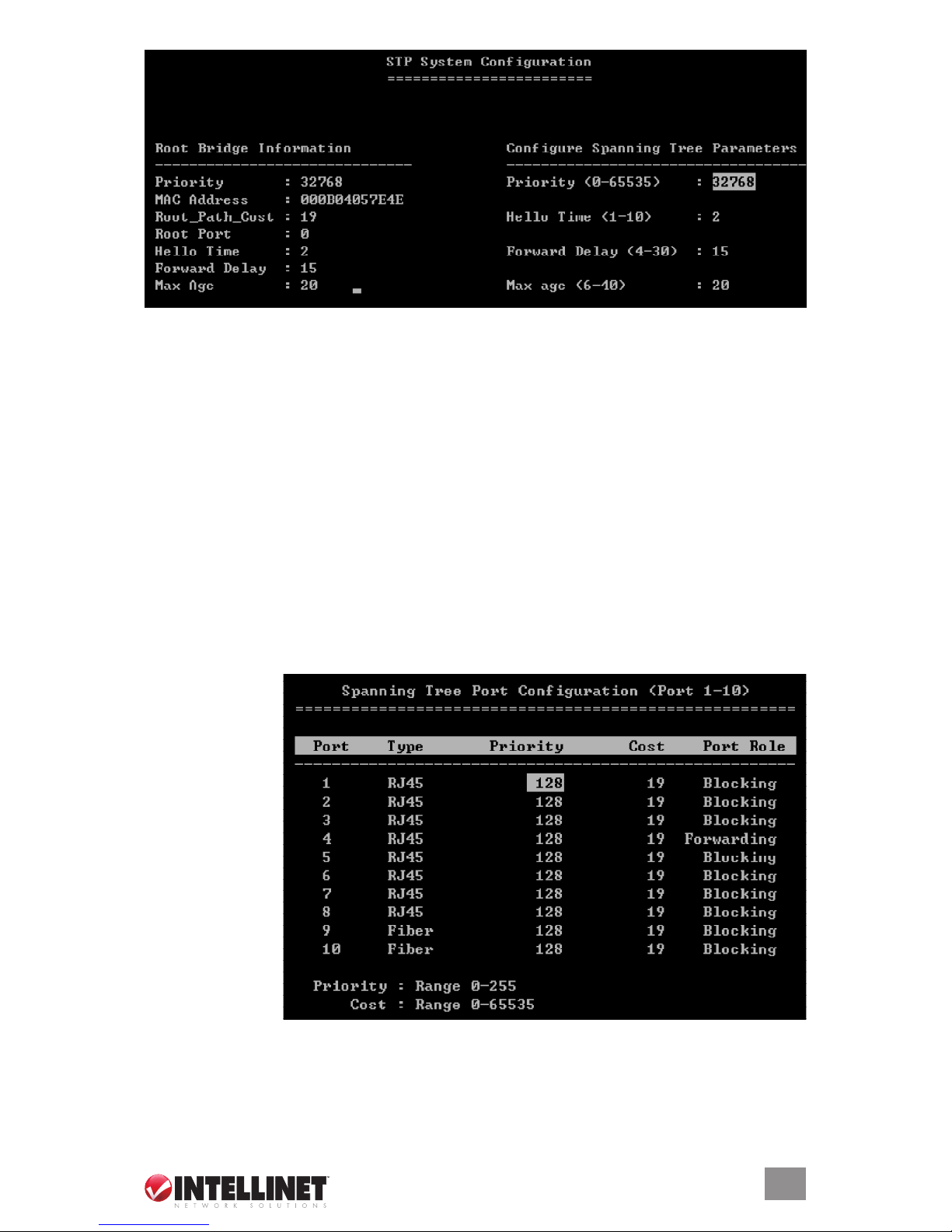
Priority: When setting the bridge priority, the limit can be from 0 (the highest priority) to 65535
(the lowest priority). The bridge priority is used in selecting the root device, root port and
designated port. The device with the highest priority becomes the STA root device. However,
if all devices have the same priority, the device with the lowest MAC address will then become
the root device.
Hello Time: This is the interval (in seconds) at which the root device transmits a conguration
message. The limit is 1 – 10 seconds.
Forward Delay: When setting the forward delay, the limit is 4 – 30 seconds. This is the maximum
time the root device will wait before changing states (e.g., listening to learning to forwarding).
Max. Age: When setting the maximum age, the limit is 6 – 40 seconds. This is the waiting time
for receiving packets before attempting to recongure the link.
4.2.3.2.3 sTP PER-PoRT ConfiguRaTions
STP allows the switch to assign a priority status to each of its ports with respect to other
networking nodes in the network. In other words, given the priority level of each node on the
network, STP determines the best route for data to ow. Ensure that this function is activated
when setting up backup links and to avoid collisions.
Press the “Tab”
key to move
through and
highlight options;
press the “Enter”
key to select/
unselect or to exit
a eld; press the
“Esc(ape)” key to
return to the main
menu. Save after
editing; unsaved
congurations will
return to default
values or the most
recent saved
values.
Priority: When setting the priority of each port, the limit is 1 – 255. The default priority is set at
128, the midpoint of this limit.
Cost: The cost assigned to each port determines the route of information ow.
Port Role: This displays the role of each port as either Forwarding or Blocking.
15
CONFIGURATION
 Loading...