

Intellinet 523547, 523554 User Manual
16/24-PORT
GIGABIT
ETHERNET
RACKMOUNT
MANAGED SWITCH
USER
MANUAL
MODEL 523547/523554
INT-523547/523554-UM-0107-01

CONTENTS
1. Introduction .......................................................................3
Front Panel............................................................................. .................4
Rear Panel................................................................ ...........................5
2. Installation ........................................................................5
Device Installation............................................................................. .......5
Network Cable Installation................................................................ ......6
3. Functions ............................................................................6
4. Switch Management .........................................................7
Managing through a Web Browser ............................................7
Managing with Command Line Interface ....................................17
5. Specifications ..................................................................24
FCC STATEMENTS
FCC Warning
This equipment has been tested and found to comply with the limits for a Class A
digital device, pursuant to part 15 of the FCC Rules. These limits are designed to
provide reasonable protection against harmful interference when the equipment
is operated in a commercial environment. This equipment generates, uses and can
radiate radio frequency energy and, if not installed and used in accordance with
the instruction manual, may cause harmful interference to radio communications.
Operation of this equipment in a residential area is likely to cause harmful
interference, in which case the user will be required to correct the interference
at his own expense.
This device complies with Part 15 of the FCC Rules. Operation is subject to the
following two conditions: 1) This device may not cause harmful interference and
2) This device must accept any interference received, including interference that
may cause undesired operation.
CE Mark Warning
This equipment complies with the requirements relating to electromagnetic
compatibility, EN 55022 class A for ITE, the essential protection requirement
of Council Directive 89/336/EEC on the approximation of the laws of the
member states relating to electromagnetic compatibility.
2
CONTENTS
section page

1. INTRODUCTION
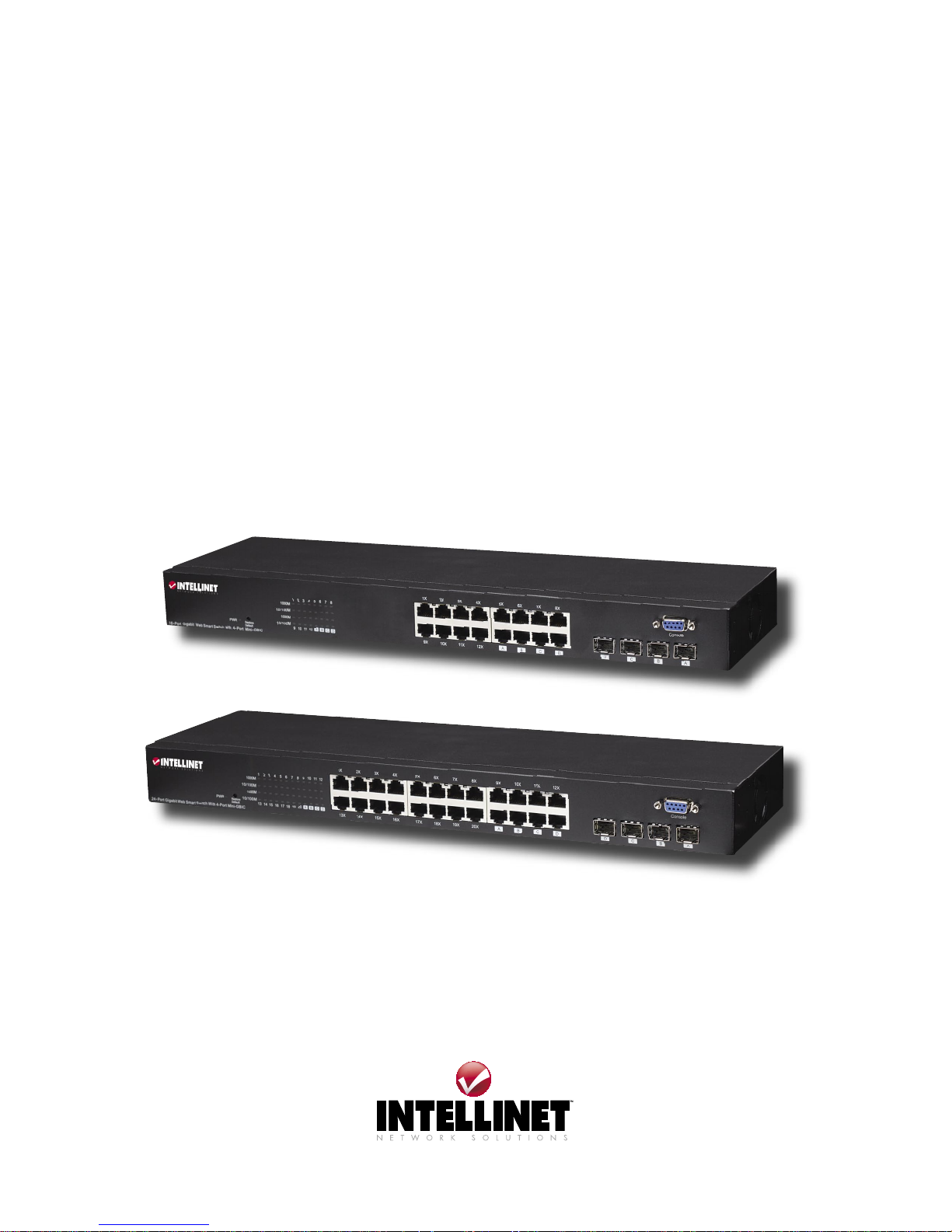
Thank you for purchasing this INTELLINET NETWORK SOLUTIONS™
Gigabit Ethernet Rackmount Managed Switch, Model 523547 (16-port)
or Model 523554 (24-port). With its 10/100/1000 Mbps gigabit ports
and user-friendly Web-based management interface, this switch boosts
networking throughput to provide a real gigabit connection that makes
it possible to transfer large, high-bandwidth files with greater speed,
efficiency and reliability.
Refer to this user manual for complete setup and operation instructions, and
enjoy the benefits of these additional features:
• 10/100/1000 auto-sensing ports automatically detect optimal network speeds
• 4 SFP mini-GBIC transceiver module slots (use of an SFP port automatically
disables the connection of its corresponding copper port)
• All RJ-45 ports with Auto-MDIX (auto uplink) support
• Supports NWay Auto-Negotiation
• Store and forward switching architecture
• Full/half duplex operation
• IEEE 802.3x flow control for full duplex
• Zero packet loss back-pressure flow control for half duplex
• Non-blocking wire-speed forwarding and filtering
• Supports port controls (speed, flow control and maximum frame size)
• Broadcast storm control with multicast packet rate settings
• Supports VLAN (16-port version: 16 groups; 24-port version: 24 groups)
and trunking (16-port version: 8 groups; 24-port version: 12 groups)
• Supports Quality of Service (QoS) with 2 priority levels
• Supports port mirroring
• Supports jumbo frames up to 9 kBytes
• Packet filtering/forwarding rates: 1,488,000 pps (1000 Mbps), 148,800 pps
(100 Mbps), 14,880 pps (10 Mbps)
• Rugged metal housing for maximum durability
• Supports up to 8192 MAC address entries
• 340 kBytes buffer memory, 16-port version;
500 kBytes buffer memory, 24-port version
• Supports SNMP management
• Configuration via Web browser or RS-232 console port
• Includes 19” rackmount brackets
• Lifetime Warranty
Package Contents
• Gigabit Ethernet Rackmount Managed Switch
• Power cable
• User manual
3
INTRODUCTION
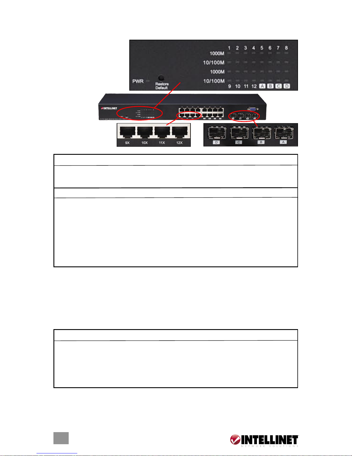
FRONT PANEL
Ports and LED indicators
are found on the front
panel of the switch. The
tables below explain
their purpose and
operation.
LEDs
NOTE: The four mini-GBIC slots (A, B, C and D) share LED indicators with the
last four RJ-45 (copper) ports (i.e., ports 13–16 on the 16-port model and ports
21–24 on the 24-port model).
Ports
The auto-negotiation feature allows ports to operate in one of the following modes:
NOTE: For the last four (highest numbered) ports, when both the fiber (miniGBIC) and copper (RJ-45) interfaces are connected, the switch automatically
disables the copper port and activates the fiber interface.
4
INTRODUCTION
System LED Status Operation
PWR Steady green Power on
Off Power off
Port LEDs Status Operation
1000M Steady green Valid port connection at 1000 Mbps
Blinking green Valid port connection; data being transmitted/
received
Off No valid link or connected at 10/100 Mbps
10/100M Steady green Valid port connection at 10/100 Mbps
Blinking green Valid port connection; data being transmitted/
received
Off No valid link or connected at 1000 Mbps
Media Speed Duplex Mode
10/100/1000 Mbps copper 10 Mbps Half/Full Duplex
100 Mbps Half/Full Duplex
1000 Mbps Full Duplex
1000 Mbps (fiber – mini-GBIC 1000 Mbps Full Duplex
required)
16-port
model
shown

Restore Default Button
Use this button to reset the switch or restore factory default settings. To reset,
press the button once. To restore factory default settings, press and hold the
button for three seconds.
REAR PANEL
Power Receptacle
Plug the female end of the power cord firmly into the receptacle and the other
end into an electrical outlet. Confirm that the power LED is lit for a normal
power status.
2. INSTALLATION
DEVICE INSTALLATION
The Gigabit Ethernet Rackmount Managed Switch can be placed directly on
your desktop or mounted in a rack. Rackmounting facilitates orderly installation
when you are going to install a series of networking devices.
Prior to use, it is recommended that the device be placed/positioned:
• with a minimum of 25 mm of clearance on the top and sides for adequate
ventilation
• away from sources of electrical noise, such as radios, transmitters and
broadband amplifiers
• where it cannot be affected by excessive moisture
Desktop
1. Attach the included rubber feet to the bottom of the device to keep it from
slipping. The recommended positions are marked on the switch.
2. Place the device on a level surface that can support the weight of the switch
(and any other items that need to be considered).
Rackmount
1. Disconnect any cables from the switch before proceeding with rackmounting.
2. Place the device on a hard, flat surface with the front facing you.
3. Position one of the two included mounting brackets over the mounting holes
on one side of the unit.
4. Insert the screws and fully tighten them with a suitable screwdriver.
5. Repeat the two previous steps for the other side of the device.
6. Insert the switch into the rack (secure with suitable screws, if desired);
reconnect cables as needed.
5
INSTALLATION

NETWORK CABLE INSTALLATION
Crossover/Straight-Through Cable
All the ports on the Gigabit Ethernet Rackmount Managed Switch support
Auto-MDI/MDI-X functionality, so both crossover and straight-through cables can
be used to connect to PCs, routers, additional switches and other devices.
Cat3/4/5/5e UTP/STP Cable
Cat3/4/5/5e UTP/STP cables provide optimal performance when the proper
cable is matched to the required transmit/receive speed, as indicated below.
3. FUNCTIONS
Jumbo Frames
With Jumbo Frames supported, the switch can transport data in fewer frames,
which helps prevent overheads, shortens processing time and reduces the
number of interruptions. NOTE: To enable Jumbo Frames, Flow Control should
be enabled first.
Flow Control and Back Pressure
Flow Control and Back Pressure both make it easier for lower-speed and
higher-speed devices to communicate with each other, ensuring that data
transmissions are correct. The 802.3x Flow Control and Back Pressure
mechanisms work for full and half duplex modes, respectively. Flow Control
can be enabled or disabled on a per-port basis.
Mirror
The Mirror function lets a network administrator monitor traffic by forwarding a
copy of the packets transferred by the monitored port to a “sniffer” port.
VLAN
With VLAN support, the network can be segmented into groups to reduce
collisions caused by heavy traffic among multiple devices. The switch supports
both port-based and 802.1Q tag-based VLAN. Port-based VLAN classifies
6
FUNCTIONS
Media Speed Recommended cable
10/100/1000 Mbps copper 10 Mbps Cat3/4/5 UTP/STP
100 Mbps Cat5 UTP/STP
1000 Mbps Cat5/5e UTP/STP
1000 Mbps fiber (mini-GBIC 1000 Mbps Cable type depends on
required the GBIC: Refer to the
mini-GBIC instructions.

incoming packets to VLANs according to their ingress port. The 802.1Q-based
VLAN adds a tag to the header of the packet to classify the VLANs.
Trunk (Aggregation)
The Trunk function integrates several ports to enlarge the bandwidth, which
helps boost the backbone connectivity. The switch allows a maximum of eight
(16-port) or twelve (24-port) groups, with eight members for each group.
Quality of Service (QoS)
QoS classifies packets based on precedence, which means the packets are
transmitted and received by their priorities. This helps high-bandwidth-demanded
applications such as VoIP to get an unobstructed connection.
Simple Network Management Protocol (SNMP)
This device is SNMP-supported, allowing it to be monitored or inspected by
an SNMP management station.
4. SWITCH MANAGEMENT
Advanced management options can be accessed through a Telnet session/
Internet browser over the network (in-band) or through a console port.
MANAGING THROUGH A WEB BROWSER
Authentication
To access the Web-based management interface, configure the management
station with an IP address and subnet mask compatible to the switch, which
has the following factory default settings:
IP address: 192.168.1.1
Subnet mask: 255.255.255.0
Default gateway: 192.168.1.254
1. Activate your Web browser and enter the above IP address in the Address
field.
2. Key in the username and password to authenticate. The factory default
value for both username and password is “admin.” Click “Apply.”
After authentication, the System Configuration page (shown on next page)
displays as the homepage. The complete Configuration menu — plus
Monitoring and Maintenance links — appears on the left side of each page
for access to all management functions.
7
MANAGEMENT
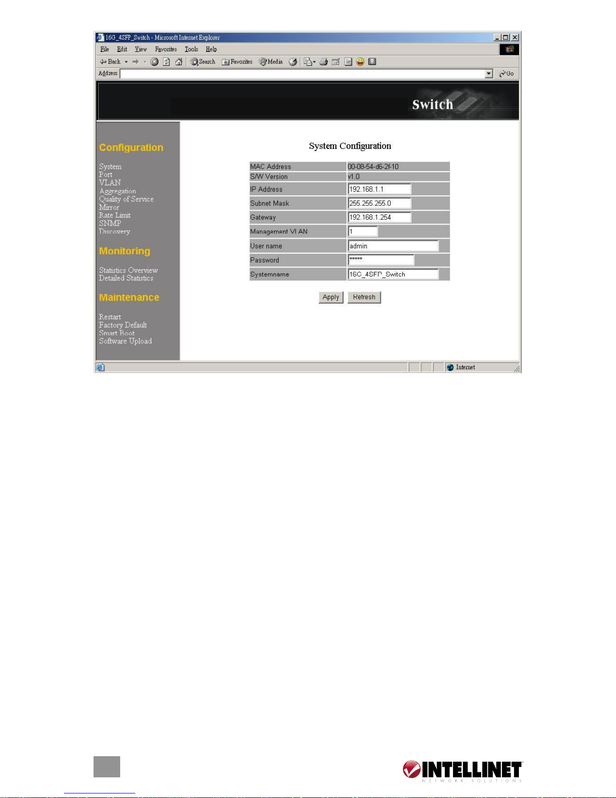
System Configuration
The System Configuration window presents the switch information and allows
the configuration of the switch properties.
MAC Address: The MAC address of this device.
S/W Version: The software version of this device.
IP Address: Set up the IP address of the switch.
Subnet Mask: Set up the subnet mask of the switch.
Gateway: Set up the gateway of the switch.
Management VLAN: The VLAN group that is allowed to access the WEB-based
management interface.
Username: The login name. (default: “admin”)
Password: The login password. (default: “admin”)
System Name: The name of the device.
To save the configuration of the system, click “Apply.” NOTE: After applying a
new IP address, a new login page will be started automatically. Login again
to proceed to other configurations.
8
MANAGEMENT
Gigabit Ethernet Rackmount Managed
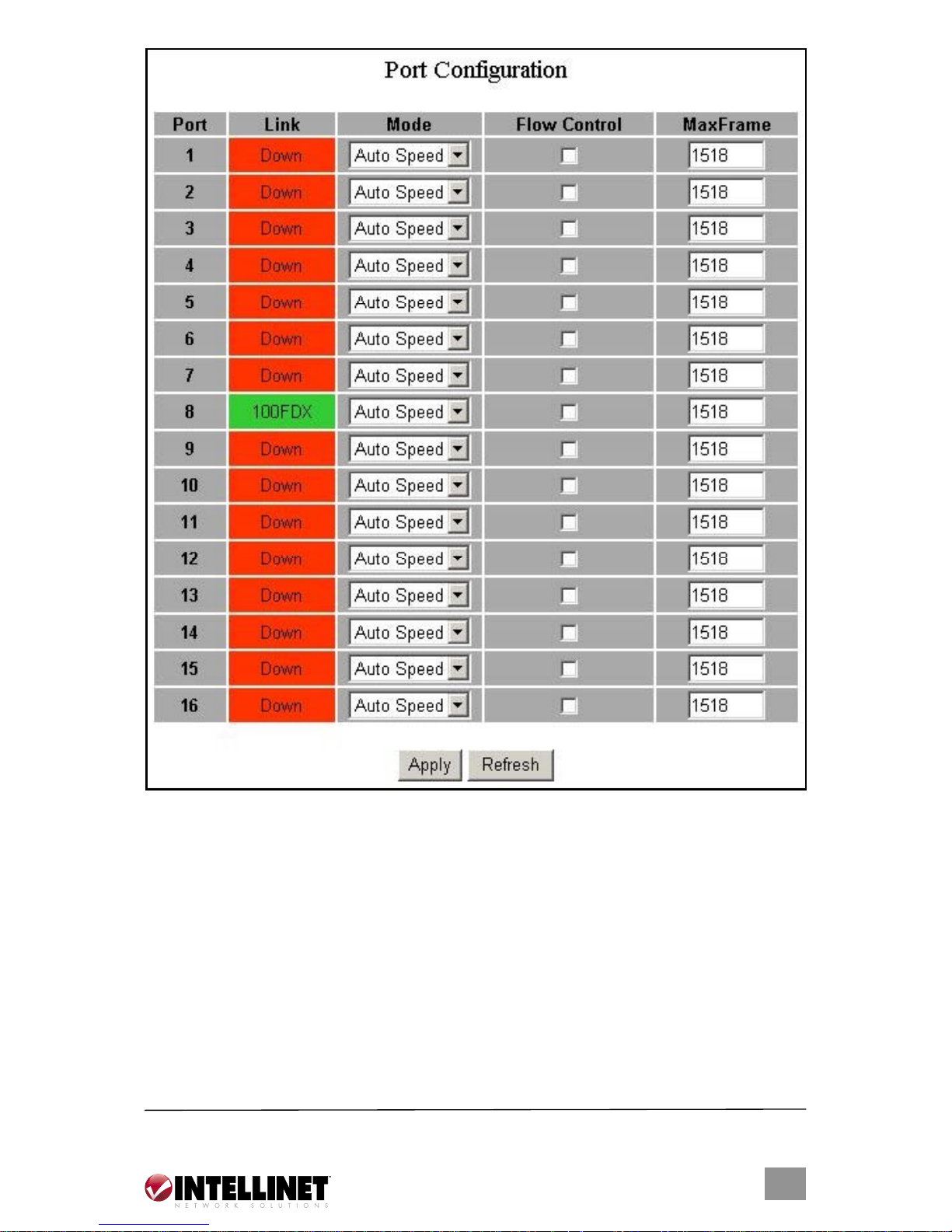
Port Configuration
The Port Configuration page shows the link status of each port and allows the
configuration of speed, flow control and maximum frame size for each port.
Link: Shows the link status of each port. The column lights green with the link
speed while there is a valid connection to this port.
Mode: Select a speed for each port. “Auto Speed” enables auto-negotiation;
“Disable” stops the port from functioning.
Flow Control: Check the boxes to enable FDX flow control; uncheck to disable.
Max Frame: Adjust the size of jumbo frames. The set length is 1518 bytes; the
maximum value can be up to 9216 bytes.
9
MANAGEMENT
*
* 16-port images are used throughout this user manual. 24-port images show identical information.
 Loading...