

Page 1

1
ADSL2+ Router
User’s Guide
Rev. 1 July 2005
Page 2

2
Table of Contents
1
Getting to Know.....................................................13
Features....................................................................................13
System Requirements............................................................13
Parts Check..............................................................................13
2
Quick Start.............................................................14
Quick Start Part 1 — Connecting the Hardware.................14
Step 1. Connect the ADSL cable..................................14
Step 2. Connect the Ethernet cable..............................14
Step 3: Install USB software and connect the
USB cable(optional).....................................................14
Step 4. Attach the power connector..............................15
Step 5. Turn on the ADSL2+ Router and
power up your systems...............................................15
Quick Start Part 2 — Configuring Your Computers...........16
Before you begin..............................................................16
Windows® XP PCs..........................................................16
Windows 2000 PCs.........................................................17
Windows ME PCs............................................................18
Windows 95, 98 PCs.......................................................19
Windows NT 4.0 workstations.......................................20
Assigning static Internet information to your
PCs.................................................................................21
Connecting a computer to the USB port......................22
Logging in to the ADSL2+ Router Quick
Configuration Page......................................................26
Default Router Settings...................................................28
Testing Your Setup.................................................................30
3 Getting Started with the Configuration Manager31
Accessing the Configuration Manager.................................31
Functional Layout....................................................................33
Page 3

Table of Contents
3
Commonly used buttons.................................................33
The Home Page and System View Table...........................34
Modifying Basic System Information....................................36
Modifying the Date and Time or Configuring
SNTP.............................................................................36
Specifying theADSL2+ Router’s Name and
Network Domain Name...............................................38
Committing Changes and Rebooting...................................39
Committing Changes.......................................................39
Rebooting the device using Configuration
Manager........................................................................40
4 Configuring the LAN and USB Interfaces............43
Connecting Your PCs via Ethernet and/or USB.................43
Configuring the LAN (Ethernet) Interface............................44
Configuring the USB Interface IP Address..........................47
5 Configuring WAN Interfaces.................................49
Configuring the ATM VC........................................................50
Modifying ATM VCs.........................................................51
Adding ATM VCs.............................................................52
Configuring PPP Interfaces...................................................53
Viewing Your Current PPP Configuration....................53
Viewing PPP Interface Details.......................................56
Adding a PPP Interface...................................................58
Configuring EoA Interfaces....................................................59
Adding EoA Interfaces....................................................61
Configuring IPoA Interfaces...................................................64
Adding IPoA Interfaces...................................................66
6 Configuring the System Operating Modes..........68
Overview of Bridges and Routers.........................................68
How Bridges Work...........................................................68
How Routers Work..........................................................69
Overview of System Operating Modes................................70
Configuring Routable and Bridgeable Interfaces................71
Page 4

4
Making Interfaces Routable (IP-Enabled)....................71
Making Interfaces Bridgeable (Bridge-Enabled)
........................................................................................71
Enabling Bridging Mode..................................................72
Common Scenarios................................................................73
Scenario 1: Routed Connection to ISP.........................73
Scenario 2: Bridged Connection to ISP........................74
Scenario 3: Routed and Bridged Connections
to ISP.............................................................................75
Configuring Special Bridging Features................................76
Configuring WAN-to-WAN Bridging..............................76
Configuring Bridge/Router AutoSense (BRAS)
Mode..............................................................................77
Configuring ZIPB Mode..................................................78
7 Viewing System IP Addresses and IP Performance
Statistics................................................................83
Viewing the ADSL2+ Router’s IP Addresses......................83
Viewing IP Performance Statistics........................................84
8
Configuring Dynamic Host Configuration Protocol
................................................................................85
Overview of DHCP..................................................................85
What is DHCP?................................................................85
Why use DHCP?..............................................................85
ADSL2+ Router DHCP modes......................................86
Configuring DHCP Server......................................................87
Guidelines for creating DHCP server address
pools...............................................................................87
Adding DHCP Server Address Pools...........................88
Viewing, modifying, and deleting address
pools...............................................................................90
Excluding IP addresses from a pool.............................91
Viewing current DHCP address assignments.............91
Configuring DHCP Relay.......................................................92
Setting the DHCP Mode.........................................................93
Page 5

Table of Contents
5
9
Configuring DNS Server Addresses....................95
About DNS...............................................................................95
Assigning DNS Addresses to PCs........................................95
Configuring DNS Relay..........................................................96
10 Configuring IP Routes...........................................98
Overview of IP Routes............................................................98
IP routing versus telephone switching..........................98
Hops and gateways.........................................................99
Using IP routes to define default gateways..................99
Do I need to define IP routes?.......................................99
Viewing the IP Routing Table..............................................100
Adding IP Routes..................................................................102
11
Configuring the Routing Information Protocol.103
RIP Overview.........................................................................103
When should you configure RIP?................................103
Configuring the ADSL2+ Router’s Interfaces with
RIP.......................................................................................104
Viewing RIP Statistics...........................................................106
12 Configuring Network Address Translation.......109
Overview of NAT...................................................................109
Viewing NAT Global Settings and Statistics......................111
Viewing NAT Rules and Rule Statistics.............................114
Viewing Current NAT Translations.....................................115
Adding NAT Rules.................................................................117
The NAPT rule: Translating between private
and public IP addresses............................................117
The RDR rule: Allowing external access to a
LAN computer.............................................................119
The Basic rule: Performing 1:1 translations...............122
The Filter rule: Configuring a Basic rule with
additional criteria........................................................123
Page 6

6
The Bimap rule: Performing two-way
translations..................................................................125
The Pass rule: Allowing specific addresses to
pass through untranslated........................................126
13 Configuring Firewall Settings.............................127
Configuring Global Firewall Settings..................................127
Managing the Blacklist..........................................................130
14
Configuring Filters and Blocking Protocols.....131
Configuring IP Filters............................................................132
Viewing Your IP Filter Configuration...........................132
Configuring IP Filter Global Settings...........................133
Creating IP Filter Rules.................................................134
IP filter rule examples....................................................139
Viewing IP Filter Statistics.............................................140
Managing Current IP Filter Sessions..........................140
Configuring Bridge Filters.....................................................142
Configuring Global Bridge Filter Settings...................142
Adding Bridge Filter Rules............................................143
Bridge Filter Rule Example...........................................147
Editing and Deleting Rules and Subrules..................148
Viewing Rule Statistics..................................................148
Blocking Protocols.................................................................149
15 Managing Access to the Configuration Program
..............................................................................153
Managing User Logins..........................................................153
Changing Login Passwords.................................................155
Enabling Management through the WAN Port.................156
Configuring SNMP................................................................157
Creating Communities...................................................157
Adding Hosts to Communities.....................................158
Viewing Hosts.................................................................158
Viewing Global SNMP Statistics..................................158
Page 7

Table of Contents
7
16
Monitoring System Status and Performing
Diagnostics..........................................................159
Viewing System Alarms........................................................159
Viewing the Alarm Table...............................................159
Viewing the System Log.......................................................160
Viewing DSL Information......................................................161
Using Diagnostics..................................................................164
Running the Diagnostics Program..............................164
Using the Ping Utility.....................................................165
Using the Traceroute Utility..........................................166
17 Upgrading the Software and Storing and
Restoring the Configuration Data......................168
Upgrading the Image............................................................168
Upgrading Using an Image Stored Locally................168
Uploading an Image Stored Remotely.......................169
Storing and Restoring Configuration Settings...................170
18
Modifying Port Settings......................................172
Overview of IP port numbers...............................................172
Modifying the ADSL2+ Router’s Port Numbers................172
19 Configuring Autodetect......................................174
How Autodetect Works.........................................................174
Autodetect Modes.................................................................174
Configuring Autodetect.........................................................175
A IP Addresses, Network Masks, and
Subnets....................................................176
IP Addresses..........................................................................176
Structure of an IP address............................................176
Network classes.............................................................177
Page 8

8
Subnet masks........................................................................177
B
Troubleshooting............................179
Page 9

Page 10

10
About this User’s Guide
This User’s Guide shows you how to set up the ADSL2+ Router
and its configuration to meet the needs of your network and Internet
connection type.
This document is organized in five major parts, each containing
several chapters:
„ Part 1, “Getting Started,” describes the product features,
provides quick start setup instructions, and explains basic
configuration information you will need to begin using the
ADSL2+ Router.
Read the chapters in Part 1 before attempting to use or
configure the device. Depending on your LAN and Internet
connection requirements, no additional configuration may
be needed before you begin using the device.
„ Part 2, “Interfaces and Operating Modes,” describes the
available operating modes and how to configure them. Part
2 also provides detailed configuration instructions for each
of the ADSL2+ Router’s interfaces.
„ Part 3, “Routing and IP-Related Features,” provides
configuration instructions and detailed information on using
the ADSL2+ Router routing features, such as DHCP server,
DNS relay, and IP routes.
„ Part 4, “Security Features,” describes how to configure
Network Address Translation (NAT) and the embedded
firewall, and how to create your own data filters.
„ Part 5, “Administrative Tasks and System Monitoring,”
provides instructions for network and system administrators
on controlling access to the ADSL2+ Router’s configuration
software, viewing system performance statistics,
diagnosing problems, upgrading the system software,
managing the configuration, and configuring special
features.
The document’s appendices explain basic Internet and networking
concepts and provide solutions to common troubleshooting issues.
Page 11

Chapter 1 About Part 1
11
Part 1
Getting Started
Page 12

Part 1 Getting Started - ADSL2+ Router User’s Guide
12
About Part 1
Part 1 provides an overview of the ADSL2+ Router’s features and
basic setup and configuration instructions. All users are encouraged
to follow these setup instructions when first installing the ADSL2+
Router on a network.
Some users may find these instructions sufficient to begin using the
device on their network, with no additional changes required to the
product settings.
Part 1 contains the following chapters:
„ Chapter 1, “Getting to Know” describes the product
features and provides a parts list.
„ Chapter 2, “Quick Start,” provides instructions for setting
up the hardware and for performing initial configuration of
the ADSL2+ Router and your LAN PCs.
„ Chapter 3, “Getting Started with the Configuration
Manager,” provides basic instructions for using the
ADSL2+ Router’s configuration program. Detailed
instructions for modifying each setting are provided in
subsequent chapters.
Page 13

13
1
Getting to Know
Features
„ ADSL2+ modem for high-speed Internet access
„ 10/100Base-T Ethernet router to provide Internet
connectivity to all computers on your LAN
„ USB port for connecting a USB-enabled PC
„ Network address translation (NAT), firewall, and IP filtering
functions to provide security for your LAN
„ Network configuration through DHCP Server and DHCP
Relay
„ Services including IP route and DNS server configuration,
RIP, and IP and DSL performance monitoring
„ Configuration program you access via your Web browser
System Requirements
You must have the following:
„ ADSL service up and running on your telephone line.
„ One or more computers each containing an Ethernet
10Base-T/100Base-T network interface card (NIC) and/or a
single computer with a USB port
„ An Ethernet hub or switch, if you are connecting the device
to more than one computer on an Ethernet network
„ For system configuration using the supplied web-based
program: a web browser such as Internet Explorer v5.0 or
later, or Netscape v6.1 or later
Parts Check
„ ADSL2+ Router
„ Power adapter
„ USB cable(Optional)
„ Ethernet cable (“straight-through” type)
„ RJ11 phone cable
„ Quick Installation Guide
„ Driver CD
Page 14

ADSL2+ Router User’s Guide
14
2 Quick Start
This Quick Start provides basic instructions for connecting the
ADSL2+ Router to a computer or LAN and to the Internet.
„ Quick Start Part 1 describes setting up the hardware.
„ Quick Start Part 2 describes how to configure Internet
properties on your computer(s) and how to install the
software for using a computer attached to the USB port
(optional).
„ Quick Start Part 3 shows you how to configure basic
settings on the ADSL2+ Router to get your LAN or PC
connected to the Internet.
After setting up and configuring the device, you can follow the
instructions on page 30 to verify that it is working properly.
This Quick Start assumes that you have already established ADSL
service with your Internet service provider (ISP). These instructions
provide a basic configuration that should be compatible with your
home or small office network setup. If necessary, refer to the
subsequent chapters for additional configuration instructions.
Quick Start Part 1 — Connecting the Hardware
In Quick Start Part 1, you connect the device to the phone jack, the
power outlet, and your computer or network.
WARNING
Before you begin, turn the power off for all devices. These
include your computer(s), your LAN hub/switch (if applicable),
and the ADSL2+ Router.
Step 1. Connect the ADSL cable.
Connect one end of the provided phone cable to the port labeled
ADSL(or DSL) on the rear panel of the device. Connect the other
end to your wall phone jack.
Step 2. Connect the Ethernet cable.
If you are connecting a LAN to the ADSL2+ Router, attach one end
of the provided Ethernet cable to a regular hub port and the other
end to the Ethernet port on the ADSL2+ Router .
Step 3: Install USB software and connect the USB
cable(optional).
You can attach a single computer to the device using a USB cable.
The USB port is useful if you have an USB-enabled PC that does
not have a network interface card for attaching to your Ethernet
Page 15

Chapter 1 About Part 1
15
network. You must install software on the PC to enable
communication; see Connecting a computer to the USB port on
page 22.
Step 4. Attach the power connector.
Connect the AC power adapter to the Power connector on the back
of the device and plug in the adapter to a wall outlet or power strip.
Step 5. Turn on the ADSL2+ Router and power up your systems.
Press the On/Off switch on the back panel of the device to the On
position. Turn on and boot up your computer(s) and any connected
LAN devices such as hubs or switches.
Page 16
ADSL2+ Router User’s Guide
16
Quick Start Part 2 — Configuring Your Computers
Quick Start Part 2 provides instructions for configuring the Internet
settings on your computers to work with the ADSL2+ Router.
Before you begin
By default, the ADSL2+ Router automatically assigns all required
Internet settings to your PCs. You need only to configure the PCs to
accept the information when it is assigned.
Note
In some cases, you may want to assign Internet information
manually to some or all of your computers rather than allow the
ADSL2+ Router to do so. See “Assigning static Internet information
to your PCs” on page 21 for instructions.
„ If you have connected your PC via the USB port, see the
USB configuration instructions on page 22.
„ If you have connected your PC(s) or LAN via Ethernet to
the ADSL2+ Router, follow the instructions that correspond
to the operating systems installed on your PCs.
Windows® XP PCs
1. In the Windows task bar, click , and then click
Control Panel.
2. Double-click the Network Connections icon.
3. In the LAN or High-Speed Internet window, right-click on the
icon corresponding to your network interface card (NIC) and
select Properties. (Often, this icon is labeled Local Area
Connection).
The Local Area Connection dialog box displays with a list of
currently installed network items.
4. Ensure that the check box to the left of the item labeled
Internet Protocol TCP/IP is checked, and click
.
5. In the Internet Protocol (TCP/IP) Properties dialog box, click
the radio button labeled Obtain an IP address
automatically. Also click the radio button labeled Obtain
DNS server address automatically.
6. Click twice to confirm your changes, and close
the Control Panel.
Page 17
Chapter 1 About Part 1
17
Windows 2000 PCs
First, check for the IP protocol and, if necessary, install it:
1. In the Windows task bar, click the Start button, point to
Settings, and then click Control Panel.
2. Double-click the Network and Dial-up Connections icon.
3. In the Network and Dial-up Connections window, right-click
the Local Area Connection icon, and then select Properties.
The Local Area Connection Properties dialog box displays with
a list of currently installed network components. If the list
includes Internet Protocol (TCP/IP), then the protocol has
already been enabled. Skip to step 10.
4. If Internet Protocol (TCP/IP) does not display as an installed
component, click .
5. In the Select Network Component Type dialog box, select
Protocol, and then click .
6. Select Internet Protocol (TCP/IP) in the Network Protocols
list, and then click .
You may be prompted to install files from your Windows 2000
installation CD or other media. Follow the instructions to install
the files.
7. If prompted, click to restart your computer with
the new settings.
Next, configure the PCs to accept IP information assigned by the
ADSL2+ Router:
8. In the Control Panel, double-click the Network and Dial-up
Connections icon.
9. In Network and Dial-up Connections window, right-click the
Local Area Connection icon, and then select Properties.
10. In the Local Area Connection Properties dialog box, select
Internet Protocol (TCP/IP), and then click .
11. In the Internet Protocol (TCP/IP) Properties dialog box, click
the radio button labeled Obtain an IP address
automatically. Also click the radio button labeled Obtain
DNS server address automatically.
12. Click twice to confirm and save your changes,
and then close the Control Panel.
Page 18
ADSL2+ Router User’s Guide
18
Windows ME PCs
1. In the Windows task bar, click the Start button, point to
Settings, and then click Control Panel.
2. Double-click the Network and Dial-up Connections icon.
3. In the Network and Dial-up Connections window, right-click
the Network icon, and then select Properties.
The Network Properties dialog box displays with a list of
currently installed network components. If the list includes
Internet Protocol (TCP/IP), then the protocol has already been
enabled. Skip to step 11.
4. If Internet Protocol (TCP/IP) does not display as an installed
component, click .
5. In the Select Network Component Type dialog box, select
Protocol, and then click .
6. Select Microsoft in the Manufacturers box.
7. Select Internet Protocol (TCP/IP) in the Network Protocols
list, and then click .
You may be prompted to install files from your Windows Me
installation CD or other media. Follow the instructions to install
the files.
8. If prompted, click to restart your computer with
the new settings.
Next, configure the PCs to accept IP information assigned by the
ADSL2+ Router:
9. In the Control Panel, double-click the Network and Dial-up
Connections icon.
10. In Network and Dial-up Connections window, right-click the
Network icon, and then select Properties.
11. In the Network Properties dialog box, select TCP/IP, and
then click .
12. In the TCP/IP Settings dialog box, click the radio button
labeled Server assigned IP address. Also click the radio
button labeled Server assigned name server address.
13. Click twice to confirm and save your changes,
and then close the Control Panel.
Page 19

Chapter 1 About Part 1
19
Windows 95, 98 PCs
First, check for the IP protocol and, if necessary, install it:
1. In the Windows task bar, click the Start button, point to
Settings, and then click Control Panel.
2. Double-click the Network icon.
The Network dialog box displays with a list of currently installed
network components. If the list includes TCP/IP, and then the
protocol has already been enabled. Skip to step 9.
3. If TCP/IP does not display as an installed component, click
.
The Select Network Component Type dialog box displays.
4. Select Protocol, and then click .
The Select Network Protocol dialog box displays.
5. Click on Microsoft in the Manufacturers list box, and then
click TCP/IP in the Network Protocols list box.
6. Click to return to the Network dialog box, and
then click again.
You may be prompted to install files from your Windows 95/98
installation CD. Follow the instructions to install the files.
7. Click to restart the PC and complete the
TCP/IP installation.
Next, configure the PCs to accept IP information assigned by the
ADSL2+ Router:
8. Open the Control Panel window, and then click the Network
icon.
9. Select the network component labeled TCP/IP, and then
click .
If you have multiple TCP/IP listings, select the listing associated
with your network card or adapter.
10. In the TCP/IP Properties dialog box, click the IP Address tab.
11. Click the radio button labeled Obtain an IP address
automatically.
12. Click the DNS Configuration tab, and then click the radio
button labeled Obtain an IP address automatically.
13. Click twice to confirm and save your changes.
You will be prompted to restart Windows.
14. Click .
Page 20
ADSL2+ Router User’s Guide
20
Windows NT 4.0 workstations
First, check for the IP protocol and, if necessary, install it:
1. In the Windows NT task bar, click the Start button, point to
Settings, and then click Control Panel.
2. In the Control Panel window, double click the Network icon.
3. In the Network dialog box, click the Protocols tab.
The Protocols tab displays a list of currently installed network
protocols. If the list includes TCP/IP, then the protocol has
already been enabled. Skip to step 9.
4. If TCP/IP does not display as an installed component, click
.
5. In the Select Network Protocol dialog box, select TCP/IP,
and then click .
You may be prompted to install files from your Windows NT
installation CD or other media. Follow the instructions to install
the files.
After all files are installed, a window displays to inform you that
a TCP/IP service called DHCP can be set up to dynamically
assign IP information.
6. Click to continue, and then click if
prompted to restart your computer.
Next, configure the PCs to accept IP information assigned by the
ADSL2+ Router:
7. Open the Control Panel window, and then double-click the
Network icon.
8. In the Network dialog box, click the Protocols tab.
9. In the Protocols tab, select TCP/IP, and then click
.
10. In the Microsoft TCP/IP Properties dialog box, click the radio
button labeled Obtain an IP address from a DHCP server.
11. Click twice to confirm and save your changes,
and then close the Control Panel.
Page 21

Chapter 1 About Part 1
21
Assigning static Internet information to your PCs
In some cases, you may want to assign Internet information to
some or all of your PCs directly (often called “statically”), rather than
allowing the ADSL2+ Router to assign it. This option may be
desirable—but not required—if:
„ You have obtained one or more public IP addresses that
you want to always associate with specific computers (for
example, if you are using a computer as a public web
server).
„ You maintain different subnets on your LAN (subnets are
described in Appendix A).
Before you begin, be sure to have the following information on hand.
Contact your ISP if necessary:
„ The IP address and subnet mask to be assigned to each
PC.
„ The IP address of the default gateway for your LAN. In
most cases, this is the address assigned to the LAN
interface on the ADSL2+ Router. By default, the LAN
interface is assigned this IP address: 192.168.1.1. (You
can change this number, or another number can be
assigned by your ISP. See Chapter 4 for more information.)
„ The IP address of your ISP’s Domain Name System (DNS)
server.
On each PC, follow the instructions on pages 16 through 20 relating
only to checking for and/or installing the IP protocol. Once it is
installed, continue to follow the instructions for displaying Internet
Protocol (TCP/IP) properties. Instead of enabling dynamic
assignment of the IP addresses for the computer, DNS server, and
default gateway, click the radio buttons that enable you to enter the
information manually.
Note
Your PCs must have IP addresses that place them in the same
subnet as the ADSL2+ Router’s LAN interface. If the IP addresses
you manually assign to your LAN PCs are in a different subnet than
the LAN interface, follow the instructions in Chapter 4 to change the
LAN interface IP address as needed.
Page 22
ADSL2+ Router User’s Guide
22
Connecting a computer to the USB port
If you use the ADSL2+ Router’s USB port to connect to a PC, you
must install the provided USB driver software on the PC. The driver
enables Ethernet-over-USB communication with the ADSL2+
Router.
Configuring the USB computer is a two-part process:
„ In USB Driver Installation Part 1, you install the USB driver
on the PC.
„ In USB Driver Installation Part 2, you configure the IP
properties on the PC.
USB Driver Installation Part 1. Installing the USB Driver on the
PC:
1. Ensure that the USB cable is not connected to the USB
port on the PC. The installation program will prompt you
when to connect the cable.
2. Copy the USB installation files to a temporary directory on
the USB computer.
3. In the folder where you copied the files, double-click on
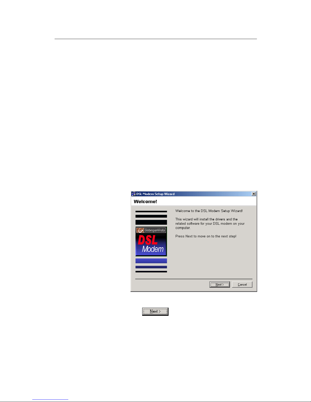
setup.exe to start the DSL Modem Setup Wizard.
The Welcome page for the DSL Modem Setup Wizard displays:
Figure 1. DSL Modem Setup Wizard— Welcome! Page
4. Click .
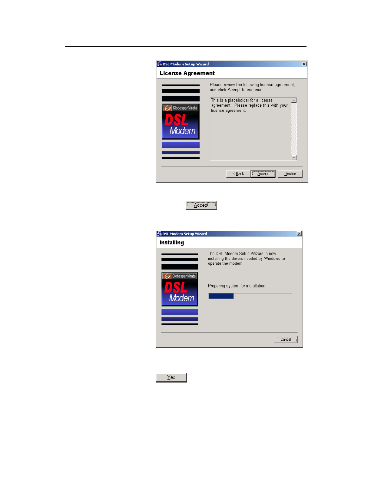
The License Agreement page displays:
Page 23
Chapter 1 About Part 1
23
Figure 2. DSL Modem Setup Wizard— License Agreement Page
5. Review the terms of the license, and, if you agree to the
terms, click .
The Installing window displays as the Wizard prepares your
system for the installation:
Figure 3. USB Setup Wizard: Installing Page
If a Microsoft digital signature dialog box displays, click
to continue.
The Installer begins copying the necessary installation files to
the required locations. When complete, a window displays,
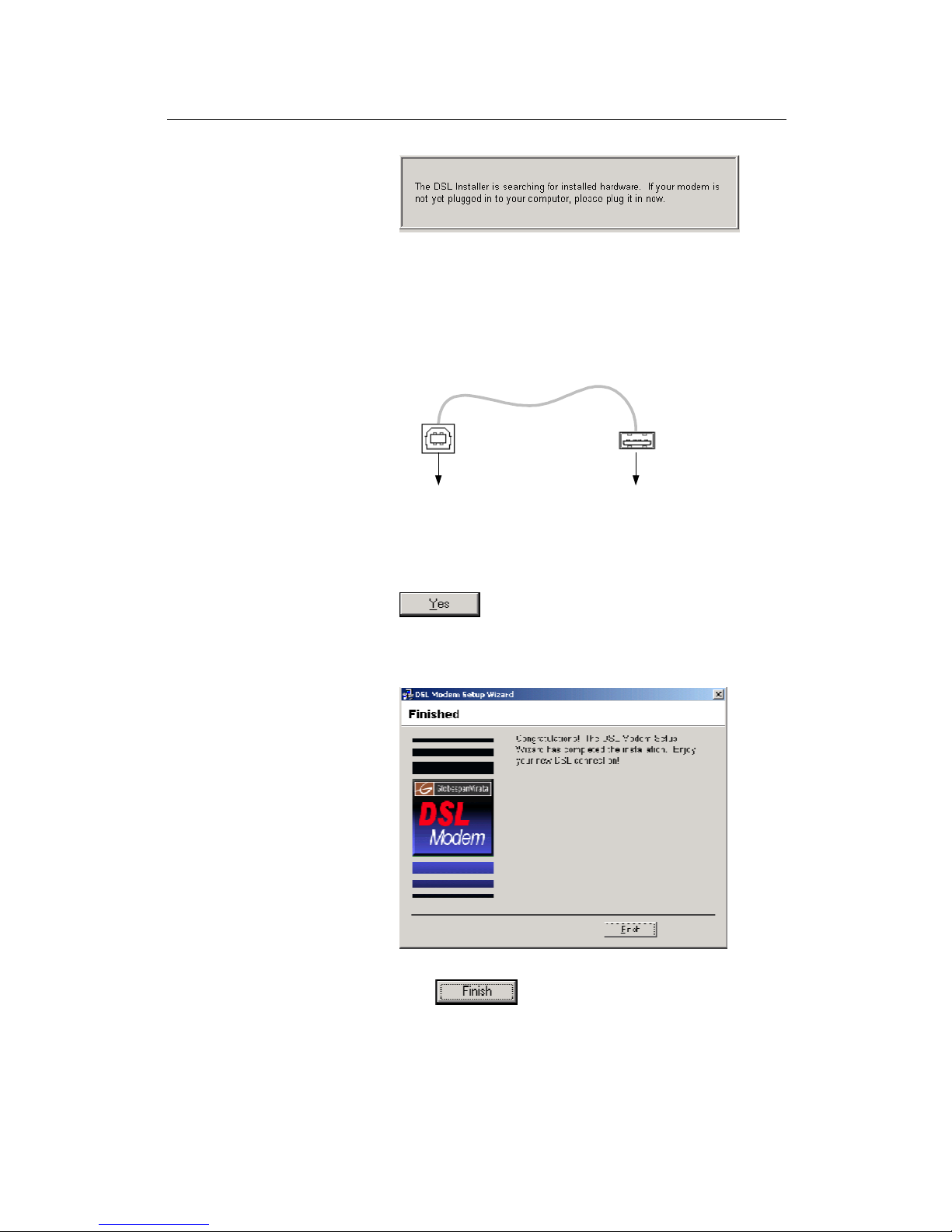
prompting you to connect the USB cable to your computer.
Page 24
ADSL2+ Router User’s Guide
24
Figure 4. USB Setup Wizard—Prompt for Hardware Plug In
6. Connect the USB cable to the ADSL-Ethernet router and to
your computer.
The provided USB cable provided has a flat connector on one
end (called Type A) and a square connector on the other (Type
B). Connect the flat connector to your PC and the square
connector to the ADSL2+ Router. See Figure 5.
To ADSLEthernet router
To PC
Figure 5. USB Cable Connectors
If a Microsoft digital signature dialog box again displays, click
to continue.
A window displays briefly, indicating that the system has found
new hardware, and the Finished page displays to complete the
installation:
Figure 6. DSL Modem Setup Wizard— Finished Page
7. Click .
You are now finished installing the driver. You do not need to restart
your computer. Proceed to USB Driver Installation Part 2 to
configure IP properties on the USB PC.
Page 25

Chapter 1 About Part 1
25
USB Driver Installation Part 2. Configuring IP properties on the
USB PC. Now that the USB driver installation is complete, you must
configure the USB PC so that its IP properties place it in the same
subnet as the ADSL2+ Router’s USB port. There are two ways to
do this:
„ The ADSL2+ Router is configured to assign an appropriate
IP address to the USB PC. If you want to use this
automatic assignment feature, called “DHCP server,” you
must configure the USB PC to accept dynamically
assigned IP information. Follow the instruction on pages 16
through 20 that correspond to the operating system
installed on your PC.
„ If you want to assign a static IP address to the PC, follow
the instructions on page 21 and use the following
information:
o
In the Network and Dial-up Connections window, be
sure to select the icon that corresponds to your new
USB connection (not the one that corresponds to your
Ethernet NIC). When you display properties for the
icon, the following text should display in the Connect
Using text box:
USB IAD LAN Modem #n
o
The USB interface on the ADSL2+ Router is
preconfigured with these properties:
USB interface IP address: 192.168.1.2
USB interface subnet mask: 255.255.255.0
Therefore, your PC must be configured as follows:
IP address: 192.168.1.n where n is a
number from 3 to 254.
Subnet mask: 255.255.255.0
Default gateway: 192.168.1.2
Page 26
ADSL2+ Router User’s Guide
26
Quick Start Part 3 — Configuring the ADSL2+ Router
In Quick Start Part 3, you log into the program on the ADSL2+
Router and configure basic settings for your Internet connection.
Your ISP should provide you with the necessary information to
complete this step.
Logging in to the ADSL2+ Router Quick Configuration Page
The ADSL2+ Router provides a preinstalled software program
called Configuration Manager that enables you to configure the
operation of the device via your Web browser. The settings that you
are most likely to need to change before using the device display on
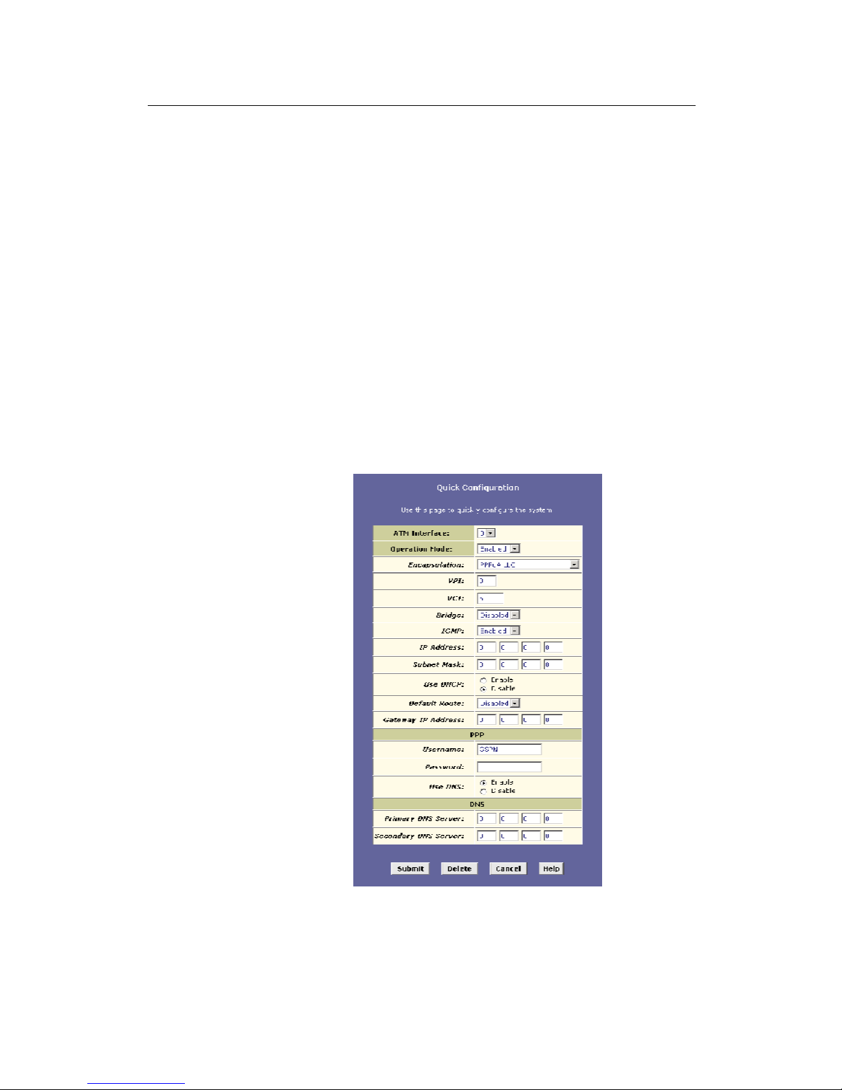
the Quick Configuration page.
Follow these instructions configure the device settings:
1. At any PC connected to the ADSL2+ Router via Ethernet or
USB, open your Web browser, and type the following URL in
the address/location box:
192.168.1.1
When you press Quick Configuration button, the page shown
in Figure 7 should display (see Appendix B, “Troubleshooting,”
if you receive an error message or the page does not display).
Figure 7. Quick Configuration Page in Configuration Manager
Page 27

Chapter 1 About Part 1
27
The fields are described in the following table. Work with your ISP to
determine which settings you need to change and refer to the
indicated chapter for more information about each setting.
Field Description
General Settings
ATM Interface
Selects the ATM interface you want to use (0). Your system
may be configured with more than one ATM interface if you
are using different types of services with your ISP.
(Chapter 5)
Operation
Mode
Enables or disables the ADSL2+ Router. When set to
"Disabled", the device cannot be used to provide Internet
connectivity or routing services for your network.
Encapsulation
Determines the type of data link your ISP uses to
communicate with your ADSL/Ethernet router. (Chapter 5)
VCI and VPI
Determine the unique data path your modem uses to
communicate with your ISP. (Chapter 5)
Bridge
Enables or disables bridging between the ADSL2+ Router
and your ISP. (Chapter 6)
IGMP
Used to enable the WAN interface to pass Internet Group
Management Protocol messages it receives to the LAN PCs.
You must also enable the LAN or USB interfaces for IGMP
(Chapter 4).
IP Address
and Subnet
Mask
If your ISP has provided a public IP address to your LAN,
enter the address and the associated subnet mask in the
boxes provided. (Note: In bridge configurations, the public IP
address may be entered on your PC rather than on the
ADSL/Ethernet router; check with your ISP.) (Chapter 5)
Use DHCP
When enabled, your ISP will assign IP addresses to your
WAN interface. When disabled, the WAN interface must
(Chapter 5).
Default Route
When enabled, specifies that the WAN interface IP address
specified above will be used as the default route for your
LAN. Whenever one of your LAN computers attempts to
access the Internet, the data will be sent via this interface.
(Chapter 5)
Gateway IP
Address
Specifies the IP address that identifies the ISP server
through which your Internet connection will be routed.
(Chapter 5)
PPP Settings
PPP User
Name and
Password
The user name and password you use to log in to your ISP.
(Note: this is not the same as the user name and password
you used to log in to Configuration Manager.) (Chapter 5)
Use DNS
Specifies whether the DNS server addresses that your LAN
will use should be supplied dynamically each time you
connect to the ISP. If you click Disable, you must configure
DNS addresses manually on each PC or on the fields below.
(Chapter 5)
DNS Settings
Primary/
Secondary
DNS Server
Specifies the primary and secondary domain name system
(DNS) server addresses provided by your ISP. (Chapter 9)
Page 28
ADSL2+ Router User’s Guide
28
2. When finished customizing these settings, click .
The settings are now in effect; however, if you reboot or if the
power is disconnected, your settings will be lost. In step 3, you
save the changes to permanent memory:
3. Click the Admin tab, and then click Commit & Reboot in
the task bar.
4. Click .
A page will display briefly to confirm your changes, and then
you will be returned to the Commit & Reboot page.
You are now finished customizing basic settings. Read the following
section to determine if you need to change additional settings.
Note
On the Quick Configuration page, you can click to
remove all existing Quick Configuration settings and return to the
default values.
Default Router Settings
The ADSL2+ Router can provide a variety of services to your
network. The device is preconfigured with default settings for use
with a typical home or small office network.
Table 1 lists some of the most important default settings; these and
other features are described fully in subsequent chapters. If you are
familiar with network configuration, review the settings in Table 1 to
verify that they meet the needs of your network. Refer to the Quick
Configuration page instructions (on page 26) or to the document
sections referenced in the table for further instructions. If you are
unfamiliar with these settings, try using the device without
modification, or contact your ISP for assistance.
Before you attempt to modify any settings, review Chapter 3 for
general information about accessing and using the Configuration
Manager program. We strongly recommend that you contact your
ISP prior to changing the default configuration.
Page 29

Chapter 1 About Part 1
29
Table 1. Default Settings Summary
Option Default Properties Explanation/Instructions
LAN interfaces — connecting to your network
Ethernet
Static IP address: 192.168.1.1
Subnet mask: 255.255.255.0
DHCP server pool of addresses:
192.168.1.3 through 192.168.1.34
The LAN interface connects the device to your Ethernet
network. Typically, you will not need to change the IP
address. See Chapter 4 for instructions.
The DHCP service (see Chapter 8) is enabled for operation
over this interface, with a pool of private IP addresses for
dynamic assignment to your LAN computers. To use this
service, you must set up your computers to accept IP
information dynamically, as described in Quick Start Part 2.
USB
Static IP address: 192.168.1.2
Subnet mask: 255.255.255.0
The USB interface can connect to a single USB-enabled
computer with an IP address in the same subnet. See
Chapter 4 for instructions.
WAN interface — connecting to the Internet
ATM VC
VPI = 0
VCI = 35
The VPI and VCI values make up a VC (virtual circuit) that
determines the path your data must take to connect over the
phone lines to the ISP. These values must be changed as
directed by your ISP. See Chapter 5 for more information.
PPP interface
PPPoE interface
Login: guest
Password: guest
The PPP interface determines the method of communication
with your ISP and logging in to their servers. A particular type
of PPP interface – PPP over Ethernet (PPPoE) – is
configured by default, with the ISP login information shown.
See “Configuring PPP Interfaces” on page 53 for instructions
on modifying this information as required by your ISP.
Services
NAT (Network
Address
Translation)
NAPT rule enabled Your computers’ private IP addresses (see DHCP above) will
be translated to your public IP address whenever they
access the Internet. See Chapter 4 for a description of the
NAT service.
Page 30

ADSL2+ Router User’s Guide
30
Testing Your Setup
The Quick Start process should enable any computer on your LAN
to use the ADSL2+ Router to access the Internet.
To test the connection, turn on the device, wait about 30 seconds,
and then verify that its LEDs are illuminated as shown in Table 2.
Table 2. LED Indicators
LED Behavior
PWR
Displays solid green to indicate that the device is turned
on.
LAN
Displays solid green when the Ethernet connection is up.
Flashes while data is being sent to and received from your
LAN PCs.
DSL Displays solid yellow when the DSL line is up. Flashes
during DSL handshake.
If the LEDs illuminate as expected, test your Internet connection
from a LAN computer (and from the USB computer, if applicable):
Open your web browser and type the URL of any external website
(such as http://www.yahoo.com). The LED labeled Internet should
be blinking rapidly and may appear solid as the device connects to
the site.
If the LEDs do not illuminate as expected or the web page does not
display, see Appendix A for troubleshooting suggestions. Or,
contact your ISP for assistance.
Page 31

31
3
Getting Started with the Configuration Manager
The ADSL2+ Router includes a preinstalled program called the
Configuration Manager, which provides an interface to the software
installed on the device. It enables you to configure the device
settings to meet the needs of your network. You access it through
your web browser from any PC connected to the ADSL2+ Router
via the LAN or USB ports.
This chapter provides basic information on using the Configuration
Manager.
Accessing the Configuration Manager
The Configuration Manager program is preinstalled into memory on
the ADSL2+ Router. To access the program, you need the following:
„ A PC or laptop connected to the LAN port on the device as
described in the Quick Start chapter.
„ A web browser installed on the PC. The program is
designed to work best with Microsoft Internet Explorer®
version 5.0, Netscape Navigator® version 6.1, or later
versions.
You can access the program from any computer connected to the
ADSL2+ Router via the LAN or USB ports.
1. From a computer connected via Ethernet or USB, open your
web browser, type the following URL in the web address (or
location) box, and press <Enter>:
http://192.168.1.1
This is the predefined IP address of the Ethernet interface
(however, since the USB interface is in the same subnet as the
LAN interface you can use this IP address from a USB
computer also).
.
A login screen displays:
Page 32

ADSL2+ Router User’s Guide
32
Figure 8. Login Screen
2. Enter your user name and password, and then click
.
The first time you log into the program, use these defaults:
Default User Name:
root
Default Password:
root
Note
You can change the password at any time (see Chapter 15 for
instructions).
The System View page on the Home tab displays each time
you log into the program (shown in Figure 10 on page 33).
Page 33

Chapter 1 About Part 1
33
Functional Layout
Configuration Manager tasks are grouped into categories, which
you can access by clicking the tabs at the top of each page. Each
tab displays the available tasks in a horizontal menu at the top of
the page. You can click on these menu items to display the specific
configuration options.
Figure 9. Web Interface Functional Layout
A new page displays when you click each task in the task bar. The
left-most task displays by default when you click on a new tab. The
same task may appear in more than one tab, when appropriate. For
example, the LAN Config task displays in both the LAN tab and the
Routing tab.
Commonly used buttons
The following buttons are used throughout the application.
Button Function
Stores in temporary system memory any changes you
have made on the current page. See “Committing
Changes” on page 39 for instructions on storing
changes permanently.
Redisplays the current page with updated statistics or
settings.
On pages that display accumulated statistics, this
button resets the statistics to their initial values.
Launches the online help for the current topic in a
separate browser window. Help is available from any
main topic page.
Selected Tab
Page 34

ADSL2+ Router User’s Guide
34
The Home Page and System View Table
The Home page displays when you first access the program or, if
another tab is already displaying, when you click on the Home tab.
Figure 10. System View Table
The Home page contains the System View table, which provides a
snapshot of your system configuration. Note that some settings link
to the related pages in Configuration Manager where you can
change the data or view details. The following table describes each
section of the System View table.
Table Heading Description
Device
Displays basic information about the ADSL2+
Router hardware and software versions, the
system uptime (since the last reboot), and the
preconfigured operating mode.
DSL
Displays the operational status, version, and
performance statistics for the DSL line. You can
click on DSL in the table heading or display the
WAN tab to view additional DSL settings, which
are described in Chapter 16.
Page 35

Chapter 1 About Part 1
35
Table Heading Description
WAN Interfaces
Displays the software name(s) and various
settings for the device interface(s) that
communicate with your ISP via DSL. Although you
only have one physical DSL port, multiple
software-defined interfaces can be configured to
use it. Most users need only one. See Chapter 5
for more information about configuring the WAN
interfaces.
For each interface, a "Lower Interface" name,
such as aal5-0, should display. You can click on
the lower interface name to view or change the
ATM VC settings that this interface uses.
LAN Interface
Displays the software names and various settings
for the device interfaces that communicate directly
with your network. These typically include an
Ethernet interface named eth-0, and may include
a USB interface named usb-0. For information on
modifying properties of these interfaces, see
Chapter 4.
Services Summary
Displays the status of various services that the
ADSL2+ Router performs to help you manage
your network. A green check mark indicates the
service is active and a red X indicates that it is
inactive:
o NAT: Translates private IP addresses to your
public IP address. The type of NAT interface
is indicated (inside/outside). (See
Chapter 12.)
o IP Filter: Allows setting up filtering rules that
accept or deny incoming or outgoing data.
(See Chapter 14.)
o RIP: Enables router-to-router communication.
(See Chapter 5.)
o DHCP Relay: Enables dynamic assignment
of IP information from your ISP to your
computers. (See Chapter 8.)
o DHCP Client: Enables dynamic assignment
of IP information from your ISP or another
computer on your network to the device’s
LAN interface. (See Chapter 4.)
o DHCP Server: Enables dynamic assignment
of IP information from the device’s built-in
DHCP server to your LAN computers. (See
Chapter 8.)
o
IGMP: Enables message forwarding from
external sources such as your ISP, based on
the Internet Group Management Protocol.
Page 36

ADSL2+ Router User’s Guide
36
Modifying Basic System Information
You can modify the system date and time or configure the device to
acquire this information from an ISP server. You can also assign a
name to the ADSL2+ Router and to the network domain in which it
resides.
Modifying the Date and Time or Configuring SNTP
You can set the system date and time manually or enable the SNTP
feature so that the device acquires this information from an ISP
server.
„ When you set the date and time manually, the information
will be held only as long as the device stays on; if power is
turned off or you reboot, the date and time revert to default
values and must again be updated.
„ When you enable SNTP (Simple Network Time Protocol),
the device connects to an ISP server that provides the date
and time information. You cannot use Configuration
Manager to specify the IP address of this server; it must
have been included as a preconfigured software setting.
Verify with the ISP that they have provided an SNTP server
address in the configuration before enabling this service.
Note
Setting the ADSL2+ Router date and time, whether manually or
through SNTP, does not affect the date and time on your PCs.
Follow these instructions to change the system date and time or
enable SNTP:
1. At the bottom of the Home page, click .
The System - Modify page displays in a separate browser
window:
Figure 11. System - Modify Page
Page 37

Chapter 1 About Part 1
37
2. Modify the fields on this page as required. The following
table describes each field:
Option Description
SNTP
To enable SNTP, click the Enable radio button.
The remaining date and time fields will be
dimmed (unavailable for entry).
Date and Time
To set the date and time manually, ensure that
the SNTP field is set to Disable. Click the date
and time check boxes to select the appropriate
values from the drop-down lists. The time
displays in military format.
Time Zone,
Daylight Savings
Time
If you are setting the date and time manually,
you can select your time zone from the dropdown list, and then click the appropriate radio
button to indicate whether Daylight Savings Time
is currently in effect.
After you initially set the time, turning DST on or
off will adjust the current displayed time by one
hour in the appropriate direction.
You must remember to change the DST option
each spring and fall — it will not change
automatically.
3. When you are finished modifying the settings, click
, and then click to return to the System
View page.
4. To save your changes to permanent memory, click the
Admin tab, and then click Commit & Reboot in the task bar.
5. Click to save your changes to permanent
memory.
Page 38

ADSL2+ Router User’s Guide
38
Specifying theADSL2+ Router’s Name and Network Domain
Name
You can specify an easy-to-remember name for the ADSL2+
Router and a domain name for the network on which it resides.
These are used only to simplify access to the Configuration
Manager program.
The Name and Domain Name fields display on the System-Modify
page, as shown in Figure 11 on page 36.
You can set a name only, or a name and domain name together.
„ If you specify a name only, then the next time you want to
access Configuration Manager, you can type this name in
the location box in your Web browser instead of typing the
numeric IP address. For example, if you named the device
myrouter (and left the Domain Name field blank), then you
could type the following in your Web browser to access
Configuration Manager:
http://myrouter
„ If you also specify a domain name for the ADSL-Ethernet
router, the next time you access Configuration Manager,
type the domain name and the device name in your Web
browser. For example, if you entered myrouter in the Name
field and mydomain.com in the Domain Name field, then
you would type the following in your Web browser to
access Configuration Manager:
http://myrouter.mydomain.com
After you enter information in these fields, follow steps 3 through 5
on page 37 to save your changes.
Note
Using a name/domain instead of the IP address to access
Configuration Manager will work only when the DNS relay feature is
enabled. DNS Relay is automatically enabled when the DNS server
address configured on your PCs is also the address assigned to the
LAN interface on theADSL2+ Router. See Chapter 9 for more
information.
Page 39

Chapter 1 About Part 1
39
Committing Changes and Rebooting
Committing Changes
Whenever you use Configuration Manager to change system
settings, the changes are initially placed in temporary storage called
random access memory or RAM. Your changes are made effective
when you submit them, but will be lost if the device is reset or
turned off.
You can commit changes to save them permanently to flash
memory.
Definition
Submitting changes activates them immediately, but saves them
only until the device is reset or powered down. Committing
changes saves them permanently.
Follow these steps to commit changes.
1. Click the Admin tab, and then click Commit & Reboot in the
task bar.
The Commit & Reboot page displays:
Figure 12. Commit & Reboot Page
2. Click . (Disregard the selection in the Reboot
Mode drop-down list; it does not affect the commit process.)
The changes are saved to permanent storage.
The previous settings are copied to backup storage so that they
can be recalled if your new settings do not work properly (see
the rebooting instructions on page 40).
Page 40

ADSL2+ Router User’s Guide
40
Rebooting the device using Configuration Manager
To reboot the device, display the Commit & Reboot page, select the
appropriate reboot mode from the drop-down menu, and then click
.
You can select from the following reboot options:
Option Description
Reboot
Reboots using the settings currently in memory,
including any changes you made and committed
during the current session.
Reboot from Default
Configuration
Reboots the device to default settings provided by
your ISP or the manufacturer. Choosing this
option erases any custom settings.
Reboot from Backup
Configuration
Reboots the device using the settings that were in
effect prior to the most recently committed
settings.
Reboot from Last
Configuration
Same as Reboot.
Reboot from Clean
Configuration
Reboots the device with no configuration. This
option will disable access to the Configuration
Manager, as no LAN interface will be defined. This
option is intended only for technicians who have a
serial port connection to the device and
knowledge of its command line interface.
Reboot from
Minimum
Configuration
Reboots the device with only these settings:
o An Ethernet interface is configured with IP
address 192.168.1.1 (mask 255.255.255.0).
o The user login is set to the following:
User Name: root
Password: root
Rebooting may take 20-30 seconds. If your browser appears to be
waiting to reconnect, press <F5> on your keyboard to refresh the
connection. Or, retype the URL (192.168.1.1 by default) in your
browser’s address box and press <Enter>. The page should
redisplay.
If you have difficulty in reconnecting to Configuration Manager after
rebooting, or if the device is not providing Internet connectivity as
before, reboot using the Reboot from Backup Configuration setting
to return to the previous settings.
WARNING
If the ADSL2+ Router provides a Reconfigure button on the back
panel (in addition to the power on/off button), do not use it to
activate new changes. This button resets the device settings to the
manufacturer’s default values. Any custom settings will be lost.
Page 41

41
Part 2
Interfaces and Operating Modes
Page 42

ADSL2+ Router User’s Guide
42
About Part 2
Part 2 explains how to configure theADSL2+ Router’s interfaces to
communicate with your LAN PC(s) and your ISP. Part 2 also
describes the device’s operating modes and explains how to
configure the interfaces to enable each mode.
Definitions
Interfaces refers to those points in the various communication
paths where the ADSL2+ Router exchanges data with external
devices. This document distinguishes between the terms port and
interface: a port is a hardware-based point of entry to or exit from
a device. Often, several software-based interfaces can be defined
to operate over the same port.
Operating modes determine which protocols the device can use
to communicate with LAN computers and the ISP, and which
product features are made available to the user.
Part 2 contains the following chapters:
„ Chapter 4, “Configuring the LAN and USB Interfaces,”
explains how to configure the Ethernet and USB interfaces,
which connect though distinct ports to your LAN hub/switch
and optional USB-enabled PC. Because the Ethernet
interface can be used to connect to multiple computers, it is
referred to as the LAN interface.
„ Chapter 5, “Configuring WAN Interfaces,” explains how
to configure the ATM Virtual Circuit (VC) interface and
higher-level interfaces that the device uses to communicate
via the DSL port.
„ Chapter 6, “Configuring the System Operating Mode,”
describes the device’s operating modes and explains how
the LAN and WAN interfaces must be configured to enable
each mode.
Page 43

43
4
Configuring the LAN and USB Interfaces
This chapter describes how to configure the interfaces on the
ADSL2+ Router that communicate with your LAN and USB
computers.
Connecting Your PCs via Ethernet and/or USB
If you are using the ADSL/Ethernet router with multiple PCs on your
LAN, you must connect the LAN via an Ethernet hub or switch to
the device's LAN port, also called the Ethernet port.
If you are using a single PC with the ADSL/Ethernet router, you
have two connection options:
„ You can connect the PC directly to the LAN port using a
crossover Ethernet cable. See Appendix B,
“Troubleshooting,” for a description of crossover versus
straight-through Ethernet cables.
„ If the PC is USB-enabled, you can connect it directly to the
device's USB port. Only one computer can be connected in
this manner.
You can also use the USB and Ethernet ports simultaneously,
connecting your LAN via the Ethernet port and a standalone PC to
the USB port.
Note
LAN and USB interfaces are preconfigured and cannot be created
using Configuration Manager. However, you can modify the
properties of an existing interface. If you require a LAN or USB
interface that was not preconfigured, contact your ISP for
assistance.
Page 44

ADSL2+ Router User’s Guide
44
Configuring the LAN (Ethernet) Interface
In order to use the device as a router on your LAN, Internet Protocol
(IP) properties must be assigned to the LAN interface. These
properties must identify the interface as residing in the same subnet
as the PCs on your LAN. (See Appendix A for an explanation of
subnets.)
Default IP properties are assigned to the LAN interface to enable
you to connect to it when you configure your PCs as described in
the Quick Start.
Note
If the IP addresses that you want to assign to your PCs are not in
the same subnet as the default LAN interface, you can use
Configuration Manager to change the LAN interface IP properties
accordingly. However, because you must access Configuration
Manager from a PC in the same subnet as the LAN interface,
initially configure one PC as indicated in the Quick Start. Then,
access Configuration Manager and change the LAN IP address as
required. When done, change the IP properties on the PC to so
that it is also in the appropriate subnet.
If your network uses a DHCP server (other than the ADSL/Ethernet
router) to assign IP addresses, you can also configure the device to
accept and use a LAN IP address assigned by that server. Similarly,
if your ISP performs DHCP serving for your network, you can
configure the device to accept an IP address assigned from the
ISP’s server. In this mode, the ADSL/Ethernet router is considered
a DHCP client of your (or your ISP’s) DHCP server.
Note
The ADSL2+ Router itself can function as a DHCP server for your
LAN computers, as described in Chapter 8, but not for its own
LAN interface.
Follow these steps to change the default LAN IP properties or to
configure the LAN interface as a DHCP client:
1. Log into Configuration Manager and click the LAN tab.
The LAN Configuration page displays:
Page 45

Chapter 2. About Part 2
45
Figure 13. LAN Configuration Page
Note
Depending on the preconfigured settings, the LAN Configuration
or USB Configuration table may not display. You cannot create
these interfaces using Configuration Manager. Contact your ISP
for assistance.
The LAN Configuration table displays the following settings:
Setting
Description
System Mode
Identifies the system operating mode for your device,
such as Routing mode, Bridging mode, or both modes
simultaneously. See Chapter 6 for information on the
system operating modes.
Get LAN
Address
Provides options for how the device’s LAN interface is
assigned an IP address:
o Manual indicates that you will be assigning a
static IP address, which you can enter in the
fields below.
o External DHCP Server indicates that your ISP will
be assigning an IP address from their own DHCP
server, dynamically each time you log on.
o Internal DHCP Server indicates that you have a
DHCP server device on your network that will
assign an address to the port.
If you choose either the internal or external server
option, the LAN interface is called a DHCP client of
the server.
Note that the public IP address assigned to you by
your ISP is not your LAN IP address. The public IP
address identifies the WAN (ADSL) port on your
ADSL/Ethernet router to the Internet. (Or, in bridge
configurations, it may be assigned to your PC.)
LAN IP
Address and
Network Mask
The IP address and network mask for the port. See
Appendix A for and overview of IP addresses and
masks.
Page 46

ADSL2+ Router User’s Guide
46
Speed/Duplex
Speed indicates the speed of the Ethernet
communication between the ADSL/Ethernet router
and the LAN PCs or hub. Duplex indicates the type of
Ethernet communication (i.e., full duplex, or halfduplex).
These settings are not user-configurable.
IGMP
Indicates whether this interface is enabled with the
Internet Group Management Protocol. When enabled,
the Ethernet interface collects and consolidates
requests from the LAN PCs to receive IGMP
messages from external computers. The interface also
forwards IGMP messages it receives on its WAN
interface to the appropriate hosts. The WAN interface
must also be enabled for the IGMP protocol (see the
Quick Configuration page and the corresponding
instructions on page 26).
MTU
The Maximum Transmission Unit specifies the size in
bytes of the largest Ethernet packet that the interface
will accept. Packets larger than this size will be
dropped.
2. Enter an IP address and mask in the fields provided or
enable an external or internal DHCP server in the Get LAN
Address field. Keep these points in mind:
„ Manually specifying an address: If you are using routing
services on you LAN such as DHCP and NAT, you must
assign a fixed LAN IP address and mask to the interface.
The IP address must be in the same subnet as your LAN
computers that connect to it. See Appendix A for an
explanation of IP addresses and network masks.
If you change the LAN IP address, you may need to update
the DHCP configuration so that the addresses that the
DHCP server dynamically assigns to your computers are
on the same subnet as the new LAN IP address. See
Chapter 8 for instructions on changing the pool of
dynamically assigned addresses.
„ Enabling DHCP: If you choose to have the LAN interface
be a DHCP client of an internal or external server, the LAN
Network Mask field will be dimmed and made unavailable
for entry. The LAN IP Address field will remain editable,
however. The address that you specify here will be used as
a request to the DHCP server. This is referred to as a
Configured IP Address in Configuration Manager. The
configured IP address is requested during communication
with the DHCP server. If the configured IP address is not
available, then system will accept another address from the
server. Even if another number is assigned, the same
configured IP address will continue to display in this field.
3. If you are using IGMP on your network, click the IGMP
Enable radio button (see the explanation of IGMP on
page 46).
4. Click .
Page 47

Chapter 2. About Part 2
47
„ If you changed the LAN IP address while working from a
PC that is connected to the device via Ethernet, then your
connection will be terminated.
„ If you changed the LAN IP address while working from a
PC connected to the device via USB, a page will display to
confirm your change and your connection will remain active.
„ If you enabled the DHCP service, the ADSL/Ethernet router
will initiate a request for an IP address from your LAN's
DHCP server. If a different IP address is assigned than was
previously configured, your current connection will be
terminated.
5. Reconfigure your PCs, if necessary, so that their IP
addresses place them in the same subnet as the new IP
address of the LAN interface. See “Quick Start Part 2 —
Configuring Your Computers,” for instructions.
6. Log into Configuration Manager by typing the new IP
address in your Web browser’s address/location box.
7. If you want the changes to be permanent, follow the
instructions on page 39 to commit them.
Configuring the USB Interface IP Address
1. If the LAN Configuration page is not already displaying,
click the LAN tab.
If the USB Configuration table does not display below the LAN
Configuration table, then your system does not support a USB
connection. Contact your ISP for assistance.
2. In the USB Configuration table, enter the IP Address and
Network Mask for the USB interface.
The IP address must place the USB interface in the same
subnet as the USB computer. The USB interface and USB
computer can also be in the same subnet as the LAN interface
and the computers attached to it.
For example, if the LAN and USB interfaces are assigned
addresses 192.168.1.1 and 192.168.1.2, respectively, then the
PCs attached to either port can be assigned addresses in the
range 192.168.1.3 through 192.168.1.254.
3. If you are using IGMP on your network, click the IGMP
Enable radio button. (See the explanation of IGMP on
page 46.)
4. In the MTU field, enter the Maximum Transmission Unit size
in bytes. This specifies the largest Ethernet packet that the
interface will accept. Packets larger than this size will be
dropped.
5. Click .
Page 48

ADSL2+ Router User’s Guide
48
„ If you changed the USB interface IP address while working
from the USB-attached computer, then the connection will
be terminated.
„ If you were using the Ethernet interface, a page will display
to confirm your change and your connection will remain
active.
6. If necessary, reconfigure your USB PC so that its IP address
places it in the same subnet as the new IP address of the
USB interface. See “Quick Start Part 2 — Configuring Your
Computers,” for instructions.
7. Log into Configuration Manager by typing the new USB
interface IP address in your Web browser’s address/location
box.
8. If you want the changes to be permanent, follow the
instructions on page 39 to commit them.
Page 49

49
5
Configuring WAN Interfaces
TheADSL2+ Router’s WAN-side interfaces are used to
communication via the DSL port.
A WAN interface comprises two layers—a lower-level ATM VC
interface and a higher-level protocol interface:
„ The ATM VC interface enables the device to communicate
using the Asynchronous Transfer Mode protocol. The ATM
protocol provides a common format for transmitting data
over a variety of hardware systems that make up the
backbone of the Internet. The virtual circuit (VC) properties
of the ATM VC interface identify a unique path that your
ADSL/Ethernet router uses to communicate via the ATMbased network with the telephone company central office
equipment.
„ The higher-level protocol interface(s) operate “on top” of
the ATM VC interface. The higher-level interface handles
the protocols needed to log onto and exchange data with
the ISP’s access server. ISPs can use several different
protocols, including the Point-to-Point Protocol (PPP),
Ethernet-over-ATM (EoA) protocol, or the Internet Protocolover-ATM (IPoA). Be sure to create the specific type of
WAN interface your ISP requires.
The following section describes configuring the AMT interface
properties. After you have defined these properties, you can
configure one of the higher level WAN interfaces to enable
communication with your ISP, as described in the subsequent
sections.
Page 50

ADSL2+ Router User’s Guide
50
Configuring the ATM VC
The device is preconfigured with an ATM VC interface called aal5-0.
You may need to change the default VC values associated with the
interface to values assigned by your ISP.
To view the current values, log into Configuration Manager, click the
WAN tab, and then click ATM VC in the task bar. The ATM VC
Configuration page displays:
Figure 14. ATM VC Configuration Page
Note
The Quick Start instructions in Chapter 2 also include ATM
interface configuration via Configuration Manager’s Quick
Configuration page. You can use either page to configure the
required values.
The ATM VC Configuration table displays the following fields.
Field Description
Interface
The name of the ATM interface to which these VC
properties apply. The ATM interface names identify
the type of traffic that can be supported, such as data
or voice. Internet data services typically use an AAL5type interface.
Vpi, Vci, and Mux
Type
These settings identify a unique ATM data path for
communication between your ADSL/Ethernet router
and your ISP.
Max Proto per
AAL5
If you are using an AAL5-type of interface, this setting
indicates the number of higher-level interfaces that
the VC can support (the higher-level interfaces can be
PPP, EoA, or IPoA interfaces). Contact your ISP to
determine which type they require.
Actions
Displays icons you can click on to modify ( ) and
delete ( ) the associated interface. You cannot
delete an ATM interface if another protocol such as
PPP, EoA, or IPoA has been defined to operate over
the ATM interface. You must first delete the higherlevel interface.
Page 51

Chapter 2. About Part 2
51
Modifying ATM VCs
Your device may contain placeholder values that you must change
to establish an ATM connection. Contact your ISP to determine
your ATM VC values. Follow these instructions to modify a
preconfigured VC:
1. From the ATM VC Configuration page, click in the
Actions column for the interface you want to modify.
The ATM VC Interface – Modify page displays:
Figure 15. ATM VC Interface – Modify Page
2. Enter the new VPI and VCI values, select the MUX type, or
change the maximum number of protocols that the VC can
carry, as directed by your ISP.
3. Click .
4. On the confirmation page, click to return to the
ATM VC Configuration page.
5. If you want the changes to be permanent, follow the
instructions on page 39 to commit them.
If you already have defined a higher-level PPP, EoA, or IPoA
interface that uses this VC, then you can verify that the new settings
work by attempting to access the Internet from a LAN/USB
computer. Contact your ISP for troubleshooting assistance.
Page 52

ADSL2+ Router User’s Guide
52
Adding ATM VCs
You can create an ATM VC interface if none has been predefined
on your system or if you use multiple services with your ISP. Each
service may require its own VC. Follow these instructions to add a
VC:
1. From the ATM VC Configuration page, click .
The ATM VC – Add page displays:
Figure 16. ATM VC – Add Page
2. Select an interface name from the VC Interface drop-down
list.
The list begins with the next available ATM VC interface name,
in sequential order.
3. Enter the VPI and VCI values assigned by your ISP, and
select the mux type from the drop-down list.
4. In the Max Proto per AAL5 text box, enter the number of
higher-level protocols (PPP, EoA, and IPoA) that the ISP
indicated that you will need to configure to operate over this
VC.
For many users, only one is required.
5. Click .
6. When the confirmation page displays, click to
return to the ATM VC Configuration page.
The new interface should now display in the ATM VC
Configuration table.
7. If you want the changes to be permanent, follow the
instructions on page 39 to commit them.
You may need to create a new WAN interface, or modify an existing
interface, so that it uses the new VC. See the instructions for
configuring a PPP (page 53), EoA (page 59), or IPoA (page 63)
interface, depending on the type you use to communicate with your
ISP.
Page 53

Chapter 2. About Part 2
53
Configuring PPP Interfaces
The Point-to-Point Protocol (PPP) is one of several protocols used
to enable communication between ISPs and their customers. PPP
handles tasks such as the following:
„ Identify the type of service the ISP should provide to a
given customer
„ Identify the customer to the ISP through a username and
password login
„ Enable the ISP to assign an Internet address and other IP
information to the customer’s DSL modem
PPP can be used only when your connection with your ISP is a
routed connection (i.e., it cannot be used for bridged connections).
For more information on bridged and routed connections, see
Chapter 6, “Configuring the System Operating Mode.”
A PPP interface can be either of two types: PPP over ATM (PPPoA)
and PPP over Ethernet (PPPoE). Although to the end user they
function similarly, the ISP’s network may be configured to handle
only one protocol type. Furthermore, an ISP may not use the PPP
protocol at all, instead offering EoA-type connections (described on
page 59). Contact your ISP before changing the preconfigured
WAN interface type.
Viewing Your Current PPP Configuration
To view your current PPP setup, log into Configuration Manager,
click the WAN tab, and then click PPP in the task bar. The Point to
Point Protocol (PPP) Configuration page displays:
Figure 17. Point to Point Protocol (PPP) Configuration Page
A PPP interface is configured as a group of software settings
associated with an ATM VC interface. Each PPP interface is given
a name, such as ppp-0, ppp-1. Users typically need only one PPP
interface; in some cases, multiple interfaces are created to allow the
user to log on to more than one account with the ISP.)
Page 54

ADSL2+ Router User’s Guide
54
You can configure the following settings on the PPP Configuration
page:
„ Inactivity TimeOut...: The time in minutes that must
elapse before a PPP connection times-out due to inactivity.
This setting applies only to PPP interfaces that are
configured as “start-on-data” interfaces. This type of
interface starts up only when it receives data, and then
returns to a down state after the specified amount of time
(see the status field on page 56).This setting works with the
following setting to determine what type of data can
activate a start-on-data interface.
„ Ignore WAN to LAN traffic while monitoring inactivity...:
When enabled, data traffic traveling in the incoming
direction—from the WAN interface to the LAN interface—
will not count as activity on the WAN interface for the
purposes of determining whether to make it inactive; i.e.,
incoming traffic will not activate a start-on-data interface.
Only LAN-to-WAN traffic will start the interface.
The PPP Configuration Table displays the following fields:
Field Description
Interface The name of the PPP interface.
VC
The virtual circuit over which this PPP data is sent.
The VC identifies the physical path the data takes to
reach your ISP.
Interface Sec Type
The type of firewall protections that are in effect on
the interface (public, private, or DMZ):
o A public interface connects to the Internet (PPP
interfaces are typically public). Packets received
on a public interface are subject to the most
restrictive set of firewall protections defined in the
software.
o A private interface connects to your LAN, such
as the Ethernet interface. Packets received on a
private interface are subject to a less restrictive
set of protections, because they originate within
the network.
o The term DMZ (de-militarized zone), in Internet
networking terms, refers to computers that are
available for both public and in-network accesses
(such as a company's public Web server).
Packets incoming on a DMZ interface -- whether
from a LAN or external source -- are subject to a
set of protections that is in between public and
private interfaces in terms of restrictiveness.
Protocol
The type of PPP protocol used. Your ISP may use
PPP-over-Ethernet (PPPoE) or PPP-over-ATM
(PPPoA).
WAN IP
The IP address currently assigned by your ISP to the
interface.
Gateway IP
The IP address, provided by your ISP, of the server
that provides you access to the Internet. See “Hops
and gateways” on page 99 for a description of
gateway addresses.
Page 55

Chapter 2. About Part 2
55
Field Description
Default Route
Indicates whether the ADSL/Ethernet router should
use the IP address assigned to this connection as its
default route. Can be Enabled or Disabled. See
Chapter 10 for an explanation of default routes.
Use DHCP When set to Enable, the device will acquire additional
IP information from the ISP's DHCP server. The PPP
connection itself acquires the device's IP address,
mask, DNS address, and default gateway address.
With Use DHCP enabled, the device will acquire IP
addresses for various other server types (WINS,
SMTP, POP3, etc. – these server types are listed on
the DHCP Server Configuration page in the LAN tab).
Use DNS When set to Enable, the DNS address learned
through the PPP connection will be distributed to
clients of the device's DHCP server. This option is
useful only when the ADSL/Ethernet Router is
configured to act as a DHCP server for your LAN.
When set to Disable, LAN hosts will use the DNS
address(es) specified in the DHCP pool (see
“Configuring DHCP Server” on page 87) and
specified in the DNS configuration (see Chapter 9).
Oper. Status
Indicates whether the link is currently up or down or if
a specific type of data exchange is under way (e.g.,
password authorization or DHCP).
Actions
You can use these icons to modify ( ), delete ( ),
and view additional details on ( ) the PPP interface.
Not all settings are available on the PPP Interface -
Modify page. To modify the other settings, you must
delete the interface and create a new one. Be sure to
submit and commit your changes if you make
modifications.
Page 56

ADSL2+ Router User’s Guide
56
Viewing PPP Interface Details
When you click to view additional details, the PPP Interface Detail page displays:
Figure 18. PPP – Detail Page
In addition to the properties defined on page 54, the Detail page
displays these fields:
Field Description
Status
Indicates which of the following interface statuses has
been manually selected:
o Start: The connection will be established for use
whenever the device is turned on or rebooted.
o Stop: The PPP interface has been manually
disabled and cannot currently be used. It can only
be used after being manually returned to the Start
state.
o Start On Data: The PPP connection will be
established automatically whenever data is sent to
the interface (e.g., when a LAN user attempts to use
the Internet), and will time-out whenever the
interface is idle for a specified amount of time.
Service Name
(This feature is available with PPPoE interfaces but not
with PPPoA interfaces.) The name of the ISP service
you are using with this PPP connection. ISPs may offer
different types of services (for example, for online
gaming or business services), each requiring a different
login and other connection properties.
Page 57

Chapter 2. About Part 2
57
Field Description
Last Fail Cause
Indicates the action that ended the previous PPP
session:
o No Valid PADO Recvd: The device initiated a PPoE
handshake but did not receive a packet in reply from
the ISP.
o
No Valid PADS Recvd: After the initial handshake,
the device did not receive a confirmation packet
from the ISP.
o Stopped by User: The user stopped the connection
(for example, by changing the Configuration
Manager settings for the PPP interface.)
o No Activity: The PPP communication timed out, in
accordance with the timeout period specified on the
PPP Configuration page.
o
Auth Failure: The ISP could not authorize the
connection based on the user name and/or
password provided.
o PADT Recvd: The ISP issued a special packet type
to terminate the PPP connection.
o VC down: The Virtual Circuit between the device
and the ISP is down.
o Internal failure: A system software failure occurred.
DNS
The IP address of the DNS server (located with your
ISP) used on this PPP connection.
SDNS
The IP address of the secondary DNS server (located
with your ISP) used on this PPP connection.
Security
Protocol
The type of PPP security your ISP uses: PAP (Password
Authentication Protocol) or CHAP (Challenge
Handshake Authentication Protocol).
Login Name
The name you use to log in to your ISP each time this
PPP connection is established.
Page 58

ADSL2+ Router User’s Guide
58
Adding a PPP Interface
Follow this procedure to add a PPP interface.
Note
If you need to use more than one PPP connection, you may be
able to create multiple PPP interfaces. The number and type of
PPP interfaces you can create depends on the lower-level ATM
VC interface type (LLC Mux or VC Mux), the Max Protocol setting
for the ATM VC interface, the PPP interface type you want to
create (PPPoA or PPPoE), and whether other WAN interface
types have already been configured (EoA or IPoA). Contact your
ISP for assistance.
1. From the PPP Configuration Page, click .
The PPP Interface – Add page displays:
Figure 19. PPP Interface – Add Page
2. Select a PPP interface name from the drop-down list, and
then enter or select data for each field.
The fields are defined in the tables on page 54 and 56.
3. Click .
A page displays to confirm your changes.
4. Click to return to the PPP page and view the new
interface in the table.
5. If you want the changes to be permanent, follow the
instructions on page 39 to commit them.
Page 59

Chapter 2. About Part 2
59
Configuring EoA Interfaces
The Ethernet-over-ATM (EoA) protocol is often referred to as
RFC1483, which is the Internet specification that defines it. It is
commonly used to carry data from an Ethernet-based local area
network over the ATM-based wide area network.
Unlike PPP, EoA can be implemented to provide a bridged
connection between a DSL modem and the ISP. In a bridged
connection, data is shared between the ISP’s network and their
customer’s as if the networks were on the same physical LAN.
Bridged connections do not use the IP protocol. EoA can also be
configured to provide a routed connection with the ISP, which uses
the IP protocol to exchange data. See Chapter 6 “Configuring the
System Operating Mode,” for more information on bridged and
routed Internet connections.
Before creating an EoA interface or modifying the default settings,
contact your ISP to determine which type of protocol they use.
Note
PPP and EoA: Bridged Internet connections must use an EoA
WAN interface. Routed Internet connections can use an EoA (if
configured with an IP address) or a PPP interface. See Chapter 5
for more information.
To view your current EoA interface configuration, log into
Configuration Manager, click the WAN tab, and then click EOA in
the task bar. The RFC1483/EoA Config page displays.
Figure 20. RFC1483/EoA Config Page
The EoA table contains a row for each EoA interface currently
defined on the device. The table may be empty.
Page 60

ADSL2+ Router User’s Guide
60
The following table describes the fields on this page:
Field Description
Interface
The name the software uses to identify the EoA
interface.
Interface Sec Type
The type of security protections in effect on the
interface (public, private, or DMZ):
o
A public interface connects to the Internet (IPoA
interfaces are typically public). Packets received
on a public interface are subject to the most
restrictive set of firewall protections defined in the
software.
o
A private interface connects to your LAN, such
as the Ethernet interface. Packets received on a
private interface are subject to a less restrictive
set of protections, because they originate within
the network.
o
The term DMZ (de-militarized zone), in Internet
networking terms, refers to computers that are
available for both public and in-network accesses
(such as a company's public Web server).
Packets incoming on a DMZ interface—whether
from a LAN or external source—are subject to a
level of protection that is in between those for
public and private interfaces.
Lower interface
EoA interfaces are defined in software, and then
associated with lower-level software and hardware
structures (at the lowest level, they are associated
with a physical port —the WAN port). This field should
reflect an interface name defined in the next lower
level of software over which the EoA interface will
operate. This will be an ATM VC interface, such as
aal5-0 .
Config IP Address
and Netmask
The IP address and network mask you want to assign
to the interface. If the interface will be used for
bridging with your ISP and you will not be using the
ADSL2+ Router as a router on your LAN, then you do
not need to specify IP information. If you enable
DHCP for this interface, then the Configured IP
address will serve only as a request to the DHCP
server. The actual address that is assigned by the
ISP may differ if this address is not available.
Use DHCP
When enabled, this setting instructs the device to
accept IP information assigned dynamically by your
ISP’s DHCP server. If the interface will be used for
bridging with your ISP and you will not be routing data
through it, leave this checkbox unselected.
Default Route
Indicates whether the ADSL2+ Router uses the IP
address assigned to this interface, if any, as its default
route for your LAN. Your system can have only one
default route. See Chapter 10 for an explanation of
default routes.
Gateway Address
The external IP address that the ADSL/Ethernet
router communicates with via the EoA interface to
gain access to the Internet. This is typically an ISP
server.
Page 61

Chapter 2. About Part 2
61
Field Description
Status
A green or red ball will display to indicate that the
interface is currently up or down, respectively. You
cannot manually enable or disable the interface; a red
ball may indicate a problem with the DSL connection
or the connection to the ISPs access server.
Action
Icons you can click on to edit ( ) or delete ( ) the
associated EoA interface.
Not all settings are available on the EoA Interface Modify page. To modify the other settings, you must
delete the interface and create a new one. Be sure to
submit and commit your changes if you make
modifications.
Adding EoA Interfaces
Follow these instructions to add an EoA interface:
1. Click the WAN tab, and then click EOA in the task bar.
2. Click .
The EoA Interface - Add page displays:
Figure 21. EoA Interface - Add Page
3. Select one of the predefined interface names from the EoA
Interface drop down list.
4. From the Interface Sec Type drop-down list, select the level
of IP Firewall to be used on this interface, as defined on
page 60.
5. In the Lower Interface field, select the lower-level interface
name over which this protocol is being configured.
If the interface will be used to provide only a bridged connection to
your ISP, skip to step 8.
6. If you are creating the EoA interface to provide a routed
Internet connection, enter the IP address for the interface in
the Conf. IP Address field, and enter the network mask.
This address serves as the public IP address for your entire
LAN and is usually assigned by your ISP.
Page 62

ADSL2+ Router User’s Guide
62
7. If your ISP will assign the IP address from their DHCP server,
click the Enable radio button in the Use DHCP field.
When DHCP is enabled, the address you entered in the Conf.
IP Address field will be requested from the DHCP server; the
server many assign a different address if necessary.
8. If you are using the EoA interface to provide a routed
connection to your ISP and you want the EoA interface to
serve as the default route for Internet access for your LAN,
ensure that the Default Route: Enable radio button is
selected. (If you have more than one WAN interface, note
that only one of them can be specified as the default route.)
If you are using the interface to provide a bridged connection,
then deselect this field.
9. In the Gateway IP Address field, enter the address of your
ISP’s access server.
10. Click .
A confirmation page displays to confirm your changes.
11. Click to return to the EoA page and view the new
interface in the table.
„ If the interface will be used to provide a bridged-only
connection or a bridged-and-routed connection to your ISP,
then continue with step 12 to enable bridging.
12. Click the Bridging tab.
The Bridge Configuration page displays:
Figure 22. Bridge Configuration Page
The Bridge Configuration page provides links (shown in red) to
the System Mode page, where you can enable or disable the
corresponding bridging services. The Bridge Configuration
page also displays a table for specifying the interfaces that
support bridging. The table may be empty if bridging has not yet
been configured.
13. In the interface table, select all interface names on which
you want to perform bridging and click .
Page 63

Chapter 2. About Part 2
63
To enable bridging with your ISP, select the EoA interface and
the LAN interface(s) (eth-0 and/or usb-0).
You can enable bridging on an IP-enabled EoA interface; in this
case, the same interface will be capable of handling both
bridged and routed data packets.
14. Click the Bridging: Enable/Disable link.
The System Mode page displays:
Figure 23. System Mode Page
You can also access the System Mode page from the task bar
in the Home tab.
15. Click the Bridging: Enabled radio button (if not already
selected), and then click .
A page will briefly display to confirm your changes, and will
return you to the Bridge Configuration page.
16. If you want the changes to be permanent, follow the
instructions on page 39 to commit them.
Page 64

ADSL2+ Router User’s Guide
64
Configuring IPoA Interfaces
An IPoA interface can be used to exchange IP packets over the
ATM network, without using an underlying Ethernet over ATM (EoA)
connection. Typically, this type of interface is used only in product
development and test environments, to eliminate unneeded
variables when evaluating IP protocol processing.
To configure an IPoA interface, log into Configuration Manager,
click the WAN tab, and then click IPoA in the task bar. The IPoA
Configuration page displays:
Figure 24. IPoA Configuration Page
The table contains a row for each IPoA interface currently defined.
The table may initially be empty. The following table describes the
fields on this page:
Field Description
Interface
The name the software uses to identify the IPoA
interface
Interface Sec Type
The type of security protections in effect on the
interface (public, private, or DMZ):
o A public interface connects to the Internet (IPoA
interfaces are typically public). Packets received
on a public interface are subject to the most
restrictive set of firewall protections defined in the
software.
o A private interface connects to your LAN, such
as the Ethernet interface. Packets received on a
private interface are subject to a less restrictive
set of protections, because they originate within
the network.
The term DMZ (de-militarized zone), in Internet
networking terms, refers to computers that are
available for both public and in-network accesses
(such as a company's public Web server). Packets
incoming on a DMZ interface—whether from a LAN
or external source—are subject to a level of
protection that is in between those for public and
private interfaces.
RFC 1577
Specifies whether the IPoA protocol to be used
complies with the IEFT specification named “RFC
1577 - Classical IP and ARP over ATM" (contact your
ISP if unsure).
Page 65

Chapter 2. About Part 2
65
Field Description
Lower interface
IPoA interfaces are defined in software, and then
associated with lower-level software and hardware
structures (at the lowest level, they are associated
with a physical port – the WAN port). This field should
reflect an interface name defined in the next lower
level of software over which the IPoA interface will
operate. This will be an ATM VC interface, such as
aal5-0.
Peer IP Address
The IP address of the remote computer you will be
connecting to via the WAN interface.
Config IP Address
and Netmask
The IP address and network mask you want to assign
to the interface. If DHCP is enabled, this address
serves as a request to the remote computer’s DHCP
server, which may assign another address.
Gateway Address
The external IP address that the ADSL/Ethernet
router communicates with via the IPoA interface to
gain access to the Internet. This is typically an ISP
server.
Status
A green or red ball will display to indicate that the
interface is currently up or down, respectively. You
cannot manually enable or disable the interface; a
down interface may indicate a problem with the DSL
connection, or with the remote IPoA computer.
Action
Icons you can click on to edit ( ) or delete ( ) the
associated IPoA interface.
Not all settings are available on the IPoA Interface Modify page. To modify the other settings, you must
delete the interface and create a new one. Be sure to
submit and commit your changes if you make
modifications.
Page 66

ADSL2+ Router User’s Guide
66
Adding IPoA Interfaces
Follow these instructions to add an IPoA interface:
1. Display the IPoA page and click .
The IPoA Interface – Add page displays:
Figure 25. IPoA Interface – Add Page
2. Select the next available interface name from the IPoA
Interface drop-down list.
3. In the Configured IP Address and Net Mask text boxes, type
the address and mask that you want to assign to the IPoA
interface.
If you enable the DHCP option (in step 6 below), then the IP
address you enter here will serve as a requested address; the
DHCP server may assign another address if necessary.
4. From the Interface Sec Type drop-down list, select the level
of firewall security for the interface: Public, Private, or DMZ
(see page 64 for definitions).
5. In the RFC 1577 field, click the Yes radio button if the
interface complies with the IETF specification RFC 1577 and
click .
6. If the remote IPoA computer provides a DHCP server, you
can click the Enable radio button in the Use DHCP field to
have the IP address dynamically assigned from the server.
7. If you want the IPoA interface to serve as the default route
for your LAN, click the Enable radio button in the Default
Route field.
Only one WAN interface can be selected as the default route.
8. In the Gateway IP Address field, enter the address of the
Internet computer to contact to gain initial access to the
Internet.
Page 67

Chapter 2. About Part 2
67
9. Click .
A confirmation page will display to confirm your changes.
10. Click to return to the IPoA page and view the new
interface in the table.
IPoA interfaces must be mapped to a lower ATM VC interface
before they can be used. Follow these instructions to map and IPoA
interface to an ATM VC:
11. In the IPoA interface table, click in the row
corresponding to the IPoA interface you want to map.
The IPoA Map Information page displays:
Figure 26. IPoA Interface – Map Page
12. From the Lower Interface drop-down list, select the ATM VC
interface you want to map the IPoA interface to, and then
click .
13. Click to return to the IPoA Configuration page.
14. If you want the changes to be permanent, follow the
instructions on page 39 to commit them.
To view all IPoA-to-ATM VC interface mappings, click at the
bottom of the IPoA Configuration page (not in the table). The IPoA
Interface – Global Map displays:
Figure 27. IPoA Interface – Global Map Page
You can click in the Action column to delete an IPoA mapping.
The IPoA interface itself is not deleted.
Page 68

68
6
Configuring the System Operating Modes
The ADSL2+ Router can operate as a router, a bridge, or both. The
system operating mode is determined by how you configure the
LAN and WAN interfaces to exchange data within your network and
with your ISP. This chapter provides an overview of how routers
and bridges work, and explains how to configure the device
interfaces and other settings to meet the needs of your network and
ISP connection type.
Overview of Bridges and Routers
Both bridges and routers enable communication between two
networks, such as a home network and ISP’s network of Internet
access servers. Although to an end-user they may appear to
provide the same functionality, bridges and routers operate
differently and provide different services. Some ISPs require their
customers to use a bridge connection, whereas others allow a
routed connection.
How Bridges Work
Bridges enable computers on two networks to communicate as if
they are on two segments of the same physical LAN. A bridge
learns the hardware IDs of all computers on each network it is
attached to. (These hardware IDs are assigned by manufacturers to
devices such as network interface cards that enable computers to
connect to networks.) The bridge determines which hardware IDs
are connected on each side of the bridge, and stores these
associations in its bridge forwarding table.
For example, when the ADSL2+ Router is acting as a bridge, it
learns to associate the hardware IDs of each of your LAN
computers with its LAN interface (e.g., eth-0 or usb-0), and the
hardware IDs of your ISP’s access server(s) with its WAN interface
(e.g., eoa-0).
When the bridge receives a data packet, the bridge compares the
packet’s destination hardware ID to the entries in its bridge
forwarding table. When the packet's destination ID matches one of
the entries, it forwards the packet through the associated interface,
where the computer with the matching hardware ID can claim the
packet. When the bridge does not recognize a packet’s destination
hardware ID, it broadcasts the packet through all of its interfaces –
to each network it is attached to.
Hardware IDs are also referred to as Media Access Control (MAC)
addresses. Ethernet is a commonly used “MAC-layer” network
protocol. Bridges provide a simple way to allow two or more
Ethernet-based networks to share data, without requiring additional
internetworking protocols. Bridges generally cannot link networks
that use different MAC-layer protocols.
Page 69

Chapter 2. About Part 2
69
How Routers Work
Routers use a higher-layer protocol than bridges use to determine
how to pass data between two networks. Routers such as the
ADSL2+ Router operate based on the Internet Protocol and use IP
addresses to identify where to send data.
Unlike a MAC address, an IP address is not permanently
associated with a particular piece of hardware, but is assigned to a
computer by its user (or by an administrator or an automated
mechanism called DHCP). Within a group of networked computers,
a router can associate each PC’s assigned IP address with its MAC
address. When a PC initiates communication through the router
outside the network, the router sends out IP packets to the Internet
on behalf of the PC, revealing only the PC’s IP address. As IP
packets are received in response, the router reconciles the IP
address with the PCs MAC address and sends Ethernet (MAClayer) packets on the network for the PC to claim.
Because they use a standardized higher-layer protocol for internetwork communication, routers can connect two or more networks
even when their underlying MAC-layer protocols differ. Routers are
considered more intelligent and flexible devices than bridges, and
often provide a variety of security and network administration
services based on the IP protocols.
For a more detailed description of how routers pass data, see
Chapter 10.
Page 70

ADSL2+ Router User’s Guide
70
Overview of System Operating Modes
The ADSL2+ Router can operate in Bridging mode, Routing mode,
or Routing and Bridging mode. You can view the currently
configured mode in the System View table on the Home page, as
shown in Figure 28.
Figure 28. Viewing the Operating Mode
The system mode that displays is not configured using a single
setting. Rather, it is determined at system startup based on whether
the device’s LAN and WAN interfaces are configured with IP
information (i.e., are “IP-enabled”), and whether the Bridging setting
on the System Mode page is enabled or disabled. The System
Mode page is located in the Home tab and is shown in Figure 30 on
page 72.
„ When the Bridging setting on the System Mode page is
disabled, then the system mode will display as “Routing.”
„ When the Bridging setting is enabled and at least one LAN
or WAN interface is IP-enabled, then the system mode will
display as “Routing and Bridging.”
„ When the Bridging setting is enabled and no interfaces are
IP enabled, then the device is considered to be in Bridging
Mode. Note, however, that in this case you would not be
able to access Configuration Manager; without being IPenabled, the Ethernet interface could not communicate
using the Internet protocol HTTP which is used to display
information in your Web browser.
Instead of focusing on selecting a system mode of operation, users
should ensure that the appropriate settings are in place to enable
communication with the ISP and to provide the required LAN
services. The correct operating mode will be selected automatically
when these settings are properly configured.
The following sections describe how to configure IP-enabled and
bridge-enabled interfaces and how to enable/disable the Bridging
setting. Several common configurations are described on
pages 73-75.
Page 71

Chapter 2. About Part 2
71
Configuring Routable and Bridgeable Interfaces
Making Interfaces Routable (IP-Enabled)
A routable or IP-enabled interface is simply one that has been
assigned an IP address. IP-enabled interfaces are capable of
forwarding IP packets. You can assign IP addresses to any LAN or
WAN interface.
„ For information about assigning IP information to LAN
interfaces (e.g., eth-0 and usb-0), see Chapter 4.
„ For information about assigning IP information to WAN
interfaces, see Chapter 5.
Making Interfaces Bridgeable (Bridge-Enabled)
When you make an interface bridgeable, you enable the software to
receive Ethernet packets through that interface, for forwarding
through the device’s other bridgeable interfaces. If an interface is
not bridgeable, it can only forward IP packets (assuming the
interface has been IP-enabled).
Note
If you create a LAN or WAN interface, it must be IP-enabled,
bridge enabled, or both. An interface that has no IP address and is
not made bridgeable will not pass any data.
Follow these instructions to specify which interfaces can perform
bridging.
1. Lon into Configuration Manager and click the Bridging tab.
The Bridge Configuration page displays:
Figure 29. Bridge Configuration Page
The Bridge Configuration page provides links (shown in red) to
the System Mode page, where you can enable or disable the
corresponding bridging services. The Bridge Configuration
page also displays a table for specifying the interfaces that
support bridging. The table may be empty if bridging has not yet
been configured.
Page 72

ADSL2+ Router User’s Guide
72
2. In the interface table, select all interface names on which
you want to perform bridging and click .
To enable bridging with your ISP, select the LAN interface
(eth-0 and/or usb-0) and the EoA interface you created for the
bridging path.
After creating bridgeable interfaces, you must enable the bridging
feature, as described in the following section, “Enabling Bridging
Mode.”
To make an interface non-bridgeable, display the Bridge
Configuration page and click next to the interface you want to
delete. Click to confirm the deletion. The interface
remains defined in the system, but is no longer capable of
performing bridging.
Enabling Bridging Mode
After you have created bridgeable interfaces, you must enable the
bridging service on the system as a whole.
1. Click the Home tab, and then click System Mode in the task
bar.
The System Mode page displays.
Figure 30. System Mode Page
You can also access the System Mode page from Bridging
page. Click any of the links that display in red near the top of
the page.
2. Click the Bridging: Enabled radio button (if not already
selected), and then click .
A page will briefly display to confirm your changes, and will
return you to the System Mode page.
3. If you want the changes to be permanent, follow the
instructions on page 39 to commit them.
The other features shown on the System Mode page are described
in “Configuring Special Bridging Features” on page on page 76.
Page 73

Chapter 2. About Part 2
73
Common Scenarios
The sections that follow describe common system configurations
that use bridging, routing, or both.
Note that you can also configure several special operating modes.
These are described in ”Configuring Special Bridging Features” on
page 76.
Scenario 1: Routed Connection to ISP
In this scenario, the ISP requires customers to have a routed
connection to their access server. For a routed connection, the LAN
and WAN interfaces must be IP-enabled. No bridging services need
to be enabled. This configuration would have these features:
„ An Ethernet (and/or USB) interface with an IP address and
network mask that identify it as being in the same subnet
as your LAN PCs. See Chapter 4 for instructions.
„ An IP-enabled WAN interface. The interface type can be
PPP or EoA. An IPoA interface can also be used, but they
are rarely used in customer settings. See Chapter 5 for
instructions.
o If an EoA interfaces is created, an IP address should
be assigned to it. Or, the interface should be
configured to receive an IP address through DHCP.
o For PPP interfaces, IP information is assigned when
the link is negotiated.
o For either type of WAN interface, the Default Gateway
check box is normally selected.
„ Each PC’s IP properties specify the ADSL/Ethernet router's
LAN interface as its gateway IP address. The PCs may
also be configured to obtain IP information automatically
from a DHCP server.
With this configuration, all IP packets originating from your LAN and
destined for the Internet will be routed to the PCs’ default gateway
(the LAN interface), then to the ADSL2+ Router’s default gateway
(the WAN interface), and then to the WAN interface’s gateway (the
ISP’s access server).
In the System View page in the Home tab, the Mode field will reflect
Routing. With no bridging services enabled, non-IP packets will be
ignored.
Page 74

ADSL2+ Router User’s Guide
74
Scenario 2: Bridged Connection to ISP
In this configuration, your ISP requires you to configure a bridged
Internet connection. For a bridged Internet connection, the WAN
interface must be bridge-enabled. The configuration would have
these features:
„ A bridge-enabled EoA WAN interface. Bridged IP
connections must use an EoA-type WAN interface. An IP
address may or may not be specified for the interface.
Note that even when the device communicates with your
ISP as a bridge, its Ethernet interface must remain IPenabled to allow you access to the Configuration Manager
program through your Web browser. The ADSL2+ Router
can also continue to provide certain IP-based services to
your LAN such as DHCP server and DNS relay.
„ Both the LAN (eth-0 and/or usb-0) and the WAN interfaces
(eoa-0) are enabled for bridging. See “Making Interfaces
Bridgeable (Bridge-Enabled)” on page 71.
„ The bridging service is enabled. See “Enabling Bridging
Mode” on page 72.
„ The ISP should provide setup instructions for the LAN
PC(s), which may involve installing software to enable
logging in to their servers (called a "PPPoE client"). The
PC's gateway IP address should be configured as the IP
address of the ISPs access server.
In the System View page in the Home tab, the Mode field will reflect
Routing and Bridging. Although you are exclusively using a bridging
connection to your ISP, the device recognizes at least one IPenabled interface (eth-0), and therefore regards the device as
capable of both routing and bridging.
Page 75

Chapter 2. About Part 2
75
Scenario 3: Routed and Bridged Connections to ISP
In this configuration, the LAN is like that described in Scenario 1, but
also includes PCs that use a bridged Internet connection. You
would then need to establish bridging services in addition to routing.
This would also be necessary if the LAN contains PCs that use nonIP networking protocols, such has AppleTalk or IPX. This
configuration would have these features:
„ An Ethernet (and/or USB) interface with an IP address and
network mask that identify it as being in the same subnet
as the LAN PCs. See Chapter 4 for instructions.
„ An WAN interface for the routing path. This can be a PPP
or EoA interface and must be IP-enabled, as described in
Scenario 1.
„ A WAN interface for the bridging path. This must be an
EoA interface. If an EoA interface was created for the
routing path, the bridging path may be able to use the
same interface. Check with your ISP.
„ Bridging is enabled on the LAN interface (eth-0 and/or
usb-0) and on the EoA interface to be used for the bridging
path. If separate interfaces are created for the bridging and
routing paths, then enable bridging only on the EoA
interface to be used for bridging. See “Making Interfaces
Bridgeable (Bridge-Enabled)” on page 71.
„ The bridging service is enabled. See “Enabling Bridging
Mode” on page 72.
„ For the PCs that will use the routing path, the LAN
interface's IP address should be specified as the IP
gateway, whether assigned statically or dynamically from a
DHCP server.
„ For the PCs that will use the bridging path, the ISP should
provide setup instructions for the LAN PC(s), which may
involve installing software to enable logging in to their
servers (called a "PPPoE client"). The PC's gateway IP
address should be configured as the IP address of the ISPs
access server.
In the System View page in the Home tab, the Mode field will reflect
you the Mode field will now reflect Routing and Bridging.
Page 76

ADSL2+ Router User’s Guide
76
Configuring Special Bridging Features
Configuring WAN-to-WAN Bridging
WAN-to-WAN bridging refers to the bridging of data between WAN
interfaces. This can occur only when bridging is enabled on the
device and it has two or more WAN interfaces. With WAN-to-WAN
bridging enabled, if a packet with an unknown destination address
is received from a WAN interface, that packet is forwarded to all the
other ports — including the other bridge-enabled WAN interface(s).
However, this ability may not be desirable for all users, due to
security concerns and bandwidth constraints. If this is the case,
WAN-to-WAN bridging should be disabled.
Follow this procedure to enable or disable WAN-to-WAN bridging:
1. Click the Bridging tab.
2. In the interface table, select all WAN interfaces and any
others on which you want to perform bridging and click
.
3. Click the WAN-to-WAN bridging: Enable/Disable link.
4. On the System Mode Page, click the WAN-to-WAN Bridging:
Enabled (or Disabled) radio button, and then click
.
A page will display briefly to confirm your changes, and will
return you to the Bridge Configuration page.
5. If you want the changes to be permanent, follow the
instructions on page 39 to commit them.
Page 77

Chapter 2. About Part 2
77
Configuring Bridge/Router AutoSense (BRAS) Mode
In Bridge-Router AutoSense (BRAS) mode, the ADSl2+ Router
chooses at startup whether to operate in Routing and Bridging
mode or in Bridging-only mode, based on information it learns while
communicating with the LAN PCs. This capability allows units to be
delivered to customers with one preconfiguration for both
deployment types.
If BRAS is to be used, the modem must be preconfigured with both
PPPoE and EoA interfaces, and bridging must be enabled. When
the modem is booted up with BRAS enabled, the mode is
determined as follows:
1. The modem comes up with both bridging and routing
enabled, with its own internal PPPoE client active.
2. If the modem subsequently detects PPPoE traffic from the
LAN PC's PPPoE client (indicating a bridge deployment),
then the modem automatically switches to bridging mode by
stopping its own PPPoE client, causing PPPoE packets to
be bridged from the LAN side.
3. Otherwise (no PPPoE traffic is detected) the modem
continues to operate as before in bridging mode (nonPPPoE traffic) as well as routing mode.
Follow these instructions to enable Bridge-Router AutoSense:
1. Ensure that both a PPPoE and an EoA interface is
established and that the EoA interface has been made
bridgeable (see “Making Interfaces Bridgeable (BridgeEnabled)” on page 71).
2. Click the Home tab to display the Home page, then select
System Mode in the task bar.
3. Ensure that the Bridging: Enabled radio button is selected.
4. Click the BRAS: Enabled radio button, and then click
.
A page displays briefly to confirm the change, and the System
Mode page redisplays.
5. If you want the changes to be permanent, follow the
instructions on page 39 to commit them.
Enabling or disabling BRAS takes effect immediately; i.e., a system
reboot is not required.
Page 78

ADSL2+ Router User’s Guide
78
Configuring ZIPB Mode
The ADSL2+ Router offers a special type of bridging mode called
ZIPB (Zero Installation PPP Bridge) mode. This mode enables the
ISP to simplify the installation process for customers who will be
using the device as a bridge. ZIPB mode also allows customers to
use the embedded firewall features, which are normally not
available on bridged connections.
Note
Contact your ISP to determine if they offer this connection type
before you configure it.
With ordinary DSL modems that use a bridged connection to the
ISP, the customer must install a program on their PC called a PPP
client. This program enables the customer to log in to the ISP’s
access server and acquire IP information that the computer needs
for all subsequent Internet communication. In ZIPB mode, the
ADSL2+ Router uses its own PPP software to communicate at
startup with the ISP. The ISP assigns the IP information to the
device’s PPP interface, which then uses its DHCP server to pass
the information on to the user’s PC. Therefore, the PPP interface
and the user’s PC both use the same IP address.
Working with your ISP, follow this procedure to enable ZIPB mode:
1. Ensure that your PCs are configured to accept IP information
assigned by a DHCP server. See “Quick Start Part 2 —
Configuring Your Computers,” for instructions.
2. Ensure that at least one PPPoE or PPPoA interface has
been created on theADSL2+ Router. See Chapter 5 for
instructions.
The Status field for the PPP interface must be set to Start on
Data. You can modify an existing interface to set this property.
Note
If you have more than one computer on your LAN and your ISP
provides multiple public IP addresses for those computers, you
must establish a PPP interface for each public IP address.
3. If it does not already exist, create a DHCP server pool with
poolid=0.
The pool should include at least one unique private IP address
for each computer on your LAN. The gateway IP address
should be set to the address of the LAN interface, which must
be in the same subnet (see Chapter 4 for instructions).
4. Enable DHCP server, as described in “Setting the DHCP
Mode” on page 93.
5. Click the Services tab to display the NAT Configuration page.
If the NAT feature is enabled, click the Disable radio button.
6. Click the Bridging tab to display the Bridging page, and then
click the ZIPB: Enable radio button.
7. Click the Bridging: Disable radio button.
Page 79

Chapter 2. About Part 2
79
8. Click .
A page displays briefly to confirm the change, and the System
Mode page redisplays.
9. If you want the changes to be permanent, follow the
instructions on page 39 to commit them.
Page 80

Page 81

81
Part 3
Routing and IP-Related Features
Page 82

ADSL2+ Router User’s Guide
82
About Part 3
Part 3 explains how to view information relating to Internet Protocol
processing, and describes configuring theADSL2+ Router’s IP
routing features.
Part 3 contains the following chapters:
„ Chapter 7, “Viewing System IP Addresses and IP
Performance Statistics,” shows how to view the IP
information associated with the device interfaces and
statistics related to IP packet processing.
„ Chapter 8, “Configuring Dynamic Host Configuration
Protocol,” describes how to configure theADSL2+
Router’s DHCP server and DHCP relay agent to
dynamically assign IP information to your LAN PCs.
„ Chapter 9, “Configuring DNS Server Addresses,”
describes how to specify the IP addresses for the Domain
Name Servers that your LAN will use when accessing the
Internet.
„ Chapter 10, “Configuring IP Routes,” describes how to
create rules that specify the device interfaces through
which data packets should be forwarded, based on their
destination IP addresses.
„ Chapter 11, “Configuring the Routing Information
Protocol,” explains how to configure a protocol that
enables the ADSL2+ Router to share its routing information
with other routers on your LAN or the Internet.
Page 83

83
7
Viewing System IP Addresses and IP
Performance Statistics
The interfaces on the ADSL2+ Router that communicate with other
network and Internet devices are identified by unique Internet
protocol (IP) addresses. You can use the Configuration Manager to
view the list of IP addresses that your device uses, and to view
other system and network performance data.
See Appendix A for a description of IP addresses and masks.
Viewing the ADSL2+ Router’s IP Addresses
To view the ADSL2+ Router’s IP addresses, click the Routing tab,
and then click IP Addr in the task bar. The IP Address Table page
displays:
Figure 31. IP Address Table Page
The table lists the IP addresses, network masks (“Net Mask”), and
interface names (“IF Name”) for each of its IP-enabled interfaces.
The listed IP addresses may include:
„ The IP address of the device’s LAN (Ethernet) port, called
eth-0. See Chapter 40 for instructions on configuring this
address.
„ The IP address of the device’s USB interface, named usb-0.
See Chapter 40 for instructions on configuring this address.
„ The IP address of the WAN (ADSL line) interface, which
your ISP and other external devices use to identify your
network. It may be identified in the Configuration Manager
by the names ppp-0, eoa-0, or ipoa-0, depending on the
protocol your device uses to communicate with your ISP.
Your ISP may assign the same address each time, or it
may change each time you reconnect.
„ The “loopback” IP address, named lo-0, of 127.0.0.1. This
special address enables the device to keep any data
addressed directly to it, rather than route the data through
the default interfaces.
If your device has additional IP-enabled interfaces, the IP
addresses of these will also display.
Page 84

ADSL2+ Router User’s Guide
84
Viewing IP Performance Statistics
You can view statistics on the processing of Internet protocol
packets (a packet is a collection of data that has been bundled for
transmission). You will not typically need to view this data, but you
may find it helpful when working with your ISP to diagnose network
and Internet data transmission problems.
To view global IP statistics, click on the IP
Address Table page. Figure 32 shows the IP Global Statistics page:
Figure 32. IP Global Statistics Page
To display updated statistics showing any new data since you
opened the page, click .
Page 85

85
8
Configuring Dynamic Host Configuration
Protocol
You can configure your network and ADSL2+ Router to use the
Dynamic Host Configuration Protocol (DHCP). This chapter
provides an overview of DHCP and instructions for implementing it
on your network.
Overview of DHCP
What is DHCP?
DHCP is a protocol that enables network administrators to centrally
manage the assignment and distribution of IP information to
computers on a network.
When you enable DHCP on a network, you allow a device — such
as the ADSL2+ Router or a router located with your ISP — to
assign temporary IP addresses to your computers whenever they
connect to your network. The assigning device is called a DHCP
server, and the receiving device is a DHCP client.
Note
If you followed the Quick Start instructions, you either configured
each LAN PC with an IP address, or you specified that it will
receive IP information dynamically (automatically). If you chose to
have the information assigned dynamically, then you configured
your PCs as DHCP clients that will accept IP addresses assigned
from a DCHP server such as the ADSL2+ Router.
The DHCP server draws from a defined pool of IP addresses and
“leases” them for a specified amount of time to your computers
when they log onto the network. It monitors, collects, and
redistributes the addresses as needed.
On a DHCP-enabled network, the IP information is assigned
dynamically rather than statically. A DHCP client can be assigned a
different address from the pool each time it reconnects to the
network.
Why use DHCP?
DHCP allows you to manage and distribute IP addresses
throughout your network from a central computer. Without DHCP,
you would have to configure each computer separately with IP
addresses and related information. DHCP is commonly used with
large networks and those that are frequently expanded or otherwise
updated.
Page 86

ADSL2+ Router User’s Guide
86
ADSL2+ Router DHCP modes
The device can be configured as a DHCP server, relay agent or
client.
„ If you configure the device as a DHCP server, it will
maintain the pool of addresses and distribute them to your
LAN computers. If the pool of addresses includes private IP
addresses, you must also configure the Network Address
Translation service, so that the private addresses can be
translated to your public IP address on the Internet.
„ If your ISP performs the DCHP server function for your
network, then you can configure the device as a DHCP
relay agent. When a computer logs onto the network, the
ADSL2+ Router contacts the ISP for the necessary IP
information, which it relays back to the computer.
„ If you have another PC or device on your network already
performing the DHCP server function, then you can
configure the device’s LAN interface to be a DHCP client of
that server (as are your PCs). This configuration is
described in Chapter 4.
Note
You can input settings for both DHCP server and DHCP relay
mode, and then activate either mode at any time. Deactivated
settings are retained for your future use.
Page 87

87
Configuring DHCP Server
Note
Before you begin, be sure to configure your PCs to accept DHCP
information assigned by a DHCP server. See “Quick Start Part
2 — Configuring Your Computers,” for instructions.
To set up DHCP server, you first define the ranges of IP addresses
that you want to be distributed to your PCs, called DHCP server
address pools.
Guidelines for creating DHCP server address pools
An IP address pool typically includes a range private addresses that
you define. LAN administrators often define private IP addresses for
use only on their networks. See “Overview of NAT” on page 109 for
an explanation of private IP addresses. You can also use DHCP
server pools to distribute multiple public IP addresses, if, for
example, these are to be shared among a larger set of LAN
computers.
You can create up to two DHCP server address pools. You can
define a single pool with addresses that can be assigned to your
LAN PCs (connected via the Ethernet port) and to a USBconnected computer, as long you have assigned to the USB and
Ethernet interfaces static IP addresses that place them in the same
subnet. See Appendix A for an explanation of subnets.
For example, assume you assigned the following addresses to the
Ethernet and USB interfaces:
Ethernet interface (eth-0): IP address 192.168.1.1
mask 255.255.255.0
USB interface (usb-0): IP address 192.168.1.2
mask 255.255.255.0
Then you could create a single pool for assignment to all your PCs:
Pool 0: 192.168.1.3 through 192.168.1.20
mask 255.255.255.0
You can create a second pool – which must be in a different subnet
than the first – if either of these circumstances apply:
„ You assigned static IP addresses to the device’s Ethernet
and USB interfaces that place them in different subnets
(note that this is not required).
Page 88

ADSL2+ Router User’s Guide
88
Adding DHCP Server Address Pools
Follow these instructions to create an IP address pool:
1. Log into Configuration Manager, click the LAN tab, and then
click DHCP Server in the task bar.
The DHCP Server Configuration page displays:
Figure 33. DHCP Configuration Page
Depending on your preconfigured settings, the table may
display up to two address pools, each in a row, or may be
empty.
2. Click .
The DHCP Server Pool – Add page displays:
Figure 34. DHCP Server Pool – Add Page
3. Enter values for the Start IP Address, End IP Address, and
Net Mask fields, which are required, and any others as
needed:
Field Description
Page 89

89
Field Description
Start/End IP
Addresses
Specifies the lowest and highest addresses in
the pool, up to a maximum range of 254
addresses. For example, if the LAN interface is
assigned IP address 192.168.1.1, then you
could create a pool with address range
192.168.1.2 – 192.168.1.254 for distribution to
your LAN computers.
Mac Address
A MAC address is a manufacturer-assigned
hardware ID that is unique for each device on a
network. Use this field only if you want to assign
a specific IP address to the computer that uses
this MAC address. If you type a MAC address
here, you must have specified the same IP
address in both the Start IP Address and End
IP Address fields.
Net Mask
Specifies which portion of each IP address in
this range refers to the network and which
portion refers to the host (computer). For a
description of network masks and LAN network
masks, see Appendix A. You can use the
network mask to distinguish which pool of
addresses should be distributed to a particular
subnet (as explained on page 87).
Domain Name
A user-friendly name that refers to the subnet
that includes the addresses in this pool. This is
used for reference only.
Gateway Address
The address of the default gateway for
computers that receive IP addresses from this
pool. If no value is specified, then the
appropriate LAN (eth-0) or USB (usb-0) port
address on the device will be distributed to
each PC as its gateway address, depending on
how each is connected.
See “Hops and gateways” on page 99 for an
explanation of gateway addresses.
DNS/SDNS
Address
The IP address of the Domain Name System
server and Secondary Domain Name System
server to be used by computers that receive IP
addresses from this pool. These DNS servers
translate common Internet names that you type
into your web browser into their equivalent
numeric IP addresses. Typically, these servers
are located with your ISP.
SMTP...SWINS
(optional)
The IP addresses of devices that perform
various services for computers that receive IP
addresses from this pool (such as the SMTP, or
Simple Mail Transfer Protocol, server which
handles e-mail traffic). Contact your ISP for
these addresses.
4. When you are done defining the pool, click .
Page 90

ADSL2+ Router User’s Guide
90
A confirmation page displays briefly to indicate that the pool has
been added successfully. After a few seconds, the DHCP
Server Pool – Add page displays with the newly added pool.
5. Follow the instructions in “Setting the DHCP Mode” on
page 93 to enable the DHCP Server.
Viewing, modifying, and deleting address pools
To view, modify, or delete an existing address pool, display the
DHCP Server Configuration page, and click the icons in the
corresponding row in the address pool table.
„ To delete an IP address pool, click , then submit and
commit your changes.
„ To view details on an IP address pool, click . A page
displays with the same information that you entered when
you added the pool.
„ To modify the pool, click . The DHCP Server Pool –
Modify page displays:
Figure 35. DHCP Server Pool – Modify Page
You can change the domain name associated with an IP
address pool or enable/disable the pool. By default, a pool
is enabled when you create it.
If you want the changes to be permanent, follow the
instructions on page 39 to commit them.
Page 91

91
Excluding IP addresses from a pool
If you have IP addresses that are designated for fixed use with
specific devices, or for some other reason you do not want to make
them available to your network, you can exclude them from the
pool. Display the DHCP Server Pool – Modify page, as shown in
Figure 35. Type each address to be excluded in the Excluded IP
field, and click . When you are done specifying excluded
addresses, click , and then use the Commit function to
save your changes to permanent memory (see page 39).
Viewing current DHCP address assignments
When the ADSL2+ Router functions as a DHCP server for your
LAN, it keeps a record of any addresses currently leased to your
computers. To view a table of all current IP address assignments,
display the DHCP Server Configuration page, and then
click .
A page displays similar to that shown in Figure 36.
Figure 36. DHCP Server Address Table Page
The DHCP Server Address Table lists any IP addresses that are
currently leased to your computers. For each leased address, the
table lists the following information:
Field Description
IP Address
The address that has been leased from the pool.
Netmask
The network mask associated with the leased address.
This identifies the network ID and host ID portions of
the address (see Appendix A for an explanation of
these terms).
Mac Address
The unique hardware ID of the computer to which the
IP address has been assigned.
Pool Start
The lower boundary of the address pool (shown here to
identify the pool from which the leased address was
assigned).
Address Type Can be Static or Dynamic. Static indicates that the IP
number has been assigned permanently to the specific
hardware device. Dynamic indicates that the number
has been leased temporarily for a specified length of
time.
Time Remaining
The amount of time left for the device to use the
assigned address. The default lease time is 30 days.
Page 92

ADSL2+ Router User’s Guide
92
Configuring DHCP Relay
Some ISPs perform the DHCP server function for their customers’
home/small office networks. In this case, you can configure the
device as a DHCP relay agent. When a computer on your network
requests Internet access, the ADSL2+ Router contacts your ISP to
obtain an IP address (and other information), and then forwards that
information to the computer. Follow these instructions to configure
DHCP relay:
First, you must configure your PCs to accept DHCP information
assigned by a DHCP server:
1. Open the Windows Control Panel and display the computer's
Networking properties. Configure the TCP/IP properties to
"Obtain an IP address automatically" (the actual text may
vary depending on your operating system). For detailed
instructions, see “Quick Start Part 2 — Configuring Your
Computers,” for instructions.
Next, you specify the IP address of the DHCP server and select the
interfaces on your network that will be using the relay service.
2. Log into the Configuration Manager, click the LAN tab, and
then click DHCP Relay in the task bar.
The DHCP Relay Configuration page displays:
Figure 37. DHCP Relay Configuration Page
3. In the DHCP Server Address fields, type the IP address of
your ISP’s DHCP server.
If you do not have this address, it is not essential to enter it here.
Requests for IP information from your LAN will be passed to the
default gateway, which should route the request appropriately.
4. Select the device’s WAN interface from the drop-down list
and click .
The WAN interface may be named ppp-0, eoa-0, or ipoa-0.
Contact your ISP if you are unsure which type to use.
(Note that you can also delete an interface from the table by
clicking in the right column.)
Page 93

93
5. Click .
A page displays to confirm your changes, and the program
returns to the DHCP Relay Configuration page.
6. Follow the instructions in “Setting the DHCP Mode” to set the
DHCP mode to DHCP Relay.
Setting the DHCP Mode
You must enable the appropriate DHCP mode to activate your
DHCP relay or DHCP server settings.
Follow these instructions to set the DHCP mode:
1. Click the LAN tab, and then click DHCP Mode in the task bar.
The DHCP Configuration page displays:
Figure 38. DHCP Configuration Page
2. From the DHCP Mode drop-down list, choose DHCP Server,
DHCP Relay, or None.
If you choose none, your LAN computers must be configured
with static IP addresses.
3. Click .
4. If you want the changes to be permanent, follow the
instructions on page 39 to commit them.
Page 94

Page 95

95
9
Configuring DNS Server Addresses
About DNS
Domain Name System (DNS) servers map the user-friendly domain
names that users type into their Web browsers (e.g., "yahoo.com")
to the equivalent numerical IP addresses that are used for Internet
routing.
When a PC user types a domain name into a browser, the PC must
first send a request to a DNS server to obtain the equivalent IP
address. The DNS server will attempt to look up the domain name
in its own database, and will communicate with higher-level DNS
servers when the name cannot be found locally. When the address
is found, it is sent back to the requesting PC and is referenced in IP
packets for the remainder of the communication.
Assigning DNS Addresses to PCs
Multiple DNS addresses are useful to provide alternatives when one
of the servers is down or is encountering heavy traffic. ISPs typically
provide primary and secondary DNS addresses, and may provide
additional addresses. Your LAN PCs learn these DNS addresses in
one of the following ways:
„ Statically: If your ISP provides you with their DNS server
addresses, you can assign them to each PC by modifying
the PCs' IP properties.
„ Dynamically from a DHCP pool: You can configure the
DHCP Server feature on the ADSL/Ethernet router and
create an address pool that specifies the DNS addresses to
be distributed to the PCs. Refer to “Configuring DHCP
Server,” on page 87 for instructions on creating DHCP
address pools.
In either case, you can specify the actual addresses of the ISP's
DNS servers (on the PC or in the DHCP pool), or you can specify
the address of the LAN interface on the ADSL/Ethernet router (e.g.,
192.168.1.1). When you specify the LAN interface IP address, the
device performs DNS relay, as described in the following section.
Note
If you specify the actual DNS server addresses on the PCs or in
the DHCP pool, the DNS relay feature is not used.
Page 96

ADSL2+ Router User’s Guide
96
Configuring DNS Relay
When you specify the ADSL2+ Router's LAN interface IP address
as the DNS address, then the device automatically performs “DNS
relay”; i.e., because the device itself is not a DNS server, it forwards
domain name lookup requests it receives from the LAN PCs to a
DNS server at the ISP. It then relays the DNS server’s response to
the PC.
When performing DNS relay, the ADSL2+ Router must maintain the
IP addresses of the DNS servers it contacts. It can learn these
addresses in either or both of the following ways:
„ Learned through PPP: If the device uses a PPP
connection to the ISP, the primary and secondary DNS
addresses can be learned via the PPP protocol. To use this
method, the "Use DNS" checkbox must be selected in the
PPP interface properties. (See “Configuring PPP
Interfaces,” on page 53 for related instructions. Note that
you cannot change this property by modifying an existing
PPP interface; you must delete the interface and recreate it
with the new setting.)
Using this option is advantageous in that you will not need
to reconfigure the PCs or the ADSL/Ethernet router if the
ISP changes their DNS addresses.
„ Configured on the ADSL/Ethernet router: You can use
the device's DNS feature to specify the ISP's DNS
addresses. If the device also uses a PPP interface with the
"Use DNS" property enabled, then these configured
addresses can be used in addition to the two addresses
learned through PPP. If "Use DNS" is not enabled, or if a
protocol other than PPP is used (such as EoA), then these
configured addresses will be used as the primary and
secondary DNS addresses.
Follow these steps to configure DNS relay:
1. Configure the LAN PCs to use the ADSL/Ethernet router's
LAN IP address as their DNS server address using either of
the following methods:
„ by assigning the LAN IP address statically to each PC
„ by inputting the LAN IP address or the address 0.0.0.0 as
the DNS address in the DHCP server pool used by the PCs.
2. If using a PPP connection to the ISP, click the "Use DNS"
check box so that the DNS server addresses it learns are
used for DNS relay.
Or, ...
If not using a PPP connection (or if you want to specify DNS
addresses in addition to those learned through PPP),
configure the DNS addresses on the ADSL/Ethernet router
as follows:
Page 97

97
a.
Click the Services tab, and then click
DNS
in the task bar. The
DNS Configuration page displays.
Figure 39. DNS Configuration Page
b. Type the IP address of the DNS server in an empty row and click
.
You can enter up to two addresses.
c.
Click the DNS Relay Poll Status check box if you want the
software to send regular test messages to the DNS servers to
ensure that they remain up (recommended). If none of the
specified DNS servers respond (including any acquired by PPP,
which do not display in the table), then an alert will display in the
System Log window (see the Admin tab, System Log page).
You can specify the interval in minutes between each DNS poll
message in the DNS Relay Poll Timeout text box.
d.
Click the Enable radio button, and then click .
3. If you want the changes to be permanent, follow the
instructions on page 39 to commit them.
Note
DNS addresses that are assigned to LAN PCs prior to enabling
DNS relay will remain in effect until the PC is rebooted. DNS relay
will only take effect when a PC's DNS address is the LAN IP
address.
Similarly, if after enabling DNS relay, you specify a DNS address
(other than the LAN IP address) in a DHCP pool or statically on a
PC, then that address will be used instead of the DNS relay
address.
Page 98

98
10
Configuring IP Routes
You can use Configuration Manager to define specific routes for
your Internet and network data. This chapter describes basic routing
concepts and provides instructions for creating routes.
Note that most users do not need to define IP routes.
Overview of IP Routes
The essential challenge of a router is: when it receives data
intended for a particular destination, which next device should it
send that data to? When you define IP routes, you provide the rules
that a computer uses to make these decisions.
IP routing versus telephone switching
IP routing decisions are similar to those made by switchboards that
handle telephone calls.
When you dial a long distance telephone number, you are first
connected to a switchboard operated by your local phone service
carrier. All calls you initiate go first to this main switchboard.
If the phone number you dialed is outside your calling area, the
switchboard opens a connection to a higher-level switchboard for
long distance calls. That switchboard looks at the area code you
dialed and connects you with another switchboard that serves that
area. This new switchboard, in turn, may look at the prefix in the
number you dialed (the middle set of three numbers) and connect to
a more localized switchboard that handles numbers with that prefix.
This final switchboard can then look at the last four digits of the
phone number to open a connection with the person or company
you dialed.
In comparison, when your computer initiates communication over
the Internet, such as viewing a web page connecting to an web
server, the data it sends out includes the IP address of the
destination computer (the “phone number”). All your outgoing
requests first go to the same router at your ISP (the first
“switchboard”). That router looks at the network ID portion of the
destination address (the “area code”) and determines which next
router to send the request to. After several such passes, the request
arrives at a router for the destination network, which then uses the
host ID portion of the destination IP address (the local “phone
number”) to route the request to the appropriate computer. (The
network ID and host ID portions of IP addresses are explained in
Appendix A.)
With both the telephone and the computer, all transactions are
initially sent to the same switchboard or router, which serves as a
gateway to other higher- or lower-level devices. No single device
knows at the outset the eventual path the data will take, but each
uses a specific part of the destination address/phone number to
make a decision about which device to connect to next.
Page 99

99
Hops and gateways
Each time Internet data is passed from one Internet address to
another, it is said to take a hop. A hop can be a handoff to a
different port on the same device, to a different device on the same
network, or to a device on an entirely different network.
When a hop passes data from one type of network to another, it
uses a gateway. A gateway is an IP address that provides initial
access to a network, just as a switchboard serves as a gateway to a
specific set of phone numbers. For example, when a computer on
your LAN requests access to a company’s web site, your ISP
serves as a gateway to the Internet. As your request reaches its
destination, another gateway provides access to the company’s
web servers.
Using IP routes to define default gateways
IP routes are defined on computers, routers, and other IP-enabled
devices to instruct them which hop to take, or which gateway to use,
to help forward data along to its specified destination.
If no IP route is defined for a destination, then IP data is passed to a
predetermined default gateway. The default gateway serves like a
higher-level telephone switchboard; it may not be able to connect
directly to the destination, but it will know a set of other devices that
can help pass the data intelligently. If it cannot determine which of
these devices provides a good next hop (because no such route
has been defined), then that device will forward the data to its
default gateway. Eventually, a high level device, using a predefined
IP route, will be able to forward the data along a path to its
destination.
Do I need to define IP routes?
Most users do not need to define IP routes. On a typical small home
or office LAN, the existing routes that set up the default gateways
for your LAN computers and for the ADSL2+ Router provide the
most appropriate path for all your Internet traffic.
„ On your LAN computers, a default gateway directs all
Internet traffic to the LAN interface on the ADSL2+ Router.
(assuming the device is configured in Routing mode). Your
LAN computers know their default gateway either because
you assigned it to them when you modified their TCP/IP
properties, or because you configured them to receive the
information dynamically from a server whenever they
access the Internet. (Each of these processes is described
in “Quick Start Part 2 — Configuring Your Computers.”)
„ On the ADSL2+ Router itself, a default gateway is defined
to direct all outbound Internet traffic to a router at your ISP.
This default gateway is assigned automatically by your ISP
whenever the device negotiates an Internet connection.
(The process for adding a default route is described on
page 102.)
You may need to define routes if your home setup includes two or
more networks or subnets, if you connect to two or more ISP
services, or if you connect to a remote corporate LAN.
Page 100

ADSL2+ Router User’s Guide
100
Viewing the IP Routing Table
All IP-enabled computers and routers maintain a table of IP
addresses that are commonly accessed by their users. For each of
these destination IP addresses, the table lists the IP address of the
first hop the data should take. This table is known as the device’s
routing table.
To view the ADSL2+ Router’s routing table, click the Routing tab.
The IP Route page displays by default:
Figure 40. IP Route Table Page
The IP Route Table displays a row for each existing route. These
include routes that were predefined on the device, routes you may
have added, and routes that the device has identified automatically
through communication with other devices.
The routing table should reflect a default gateway, which directs
outbound Internet traffic to your ISP. This default gateway is shown
in the row containing destination address 0.0.0.0.
 Loading...