

Intellinet 522205, 522212 User Manual

User Guide
Revision: 2.0

Contents
1. System Requirements ...........................................................................................................................1-1
2. Login.......................................................................................................................................................2-1
Status ....................................................................................................................................................3-1
3.
3.1 Home Page ..................................................................................................................................................................... 3-1
3.2 ADSL Status Page........................................................................................................................................................... 3-3
4. LAN Page..............................................................................................................................................4-1
5. PPP Page..............................................................................................................................................5-1
6. Configuration Pages .............................................................................................................................6-1
6.1 WAN Configuration......................................................................................................................................................... 6-1
6.1.1 Per VC Settings .............................................................................................................................................. 6-2
6.1.2 MAC Spoofing ................................................................................................................................................ 6-3
6.1.3 ATM ................................................................................................................................................................ 6-3
6.1.4 Encapsulation, Bridge, PPP, and DHCP Client................................................................................................ 6-3
6.1.4.1 PPP Configuration .......................................................................................................................... 6-4
6.1.5 IGMP .............................................................................................................................................................. 6-5
6.2 LAN Configuration .......................................................................................................................................................... 6-6
6.2.1 Ethernet Mode Setting .................................................................................................................................... 6-7
6.3 PPP Configuration .......................................................................................................................................................... 6-8
6.4 NAT Configuration ........................................................................................................................................................ 6-11
6.4.1 NAT (Static) and NAPT (Static) .................................................................................................................... 6-11
6.5 Virtual Server Configuration ......................................................................................................................................... 6-14
6.6 Bridge Filtering ............................................................................................................................................................. 6-16
6.7 DNS Configuration........................................................................................................................................................ 6-17
6.8 Save Settings................................................................................................................................................................ 6-19
6.9 Reboot Without Saving................................................................................................................................................. 6-22

7. Admin Privilege ....................................................................................................................................7-1
7.1 WAN Status .................................................................................................................................................................... 7-1
7.2 ATM Status ..................................................................................................................................................................... 7-2
7.3 TCP Status ...................................................................................................................................................................... 7-3
7.4 Route Table..................................................................................................................................................................... 7-4
7.4.1 New Enhancement for Routing Table ............................................................................................................. 7-5
7.4.2 System Default Gateway Configuration .......................................................................................................... 7-5
7.4.3 Route Configuration ....................................................................................................................................... 7-5
7.5 Learned MAC Table......................................................................................................................................................... 7-6
7.6 ADSL Configuration ........................................................................................................................................................ 7-7
7.7 RIP Configuration ........................................................................................................................................................... 7-8
7.7.1 RIP Per Interface Configuraiton...................................................................................................................... 7-9
7.8 Password Configuration ............................................................................................................................................... 7-11
7.8.1 Admin ........................................................................................................................................................... 7-11
7.8.2 User .............................................................................................................................................................. 7-12
7.9 Miscellaneous Configuration ........................................................................................................................................ 7-13
7.10 Reset to Factory Default ............................................................................................................................................... 7-15
7.11 Diagnostic Test ............................................................................................................................................................. 7-16
7.12 Code Image Update ...................................................................................................................................................... 7-18
7.13 Network Code Image Update ........................................................................................................................................ 7-19
7.13.1 Firmware....................................................................................................................................................... 7-19
7.13.2 Boot Code..................................................................................................................................................... 7-20
7.14 System Log................................................................................................................................................................... 7-21

1. System Requirements
• Computer
− PC and MAC
− 32 MB RAM minimum
− 20 MB of free disk space minimum
− Ethernet Network Interface Controller (NIC) RJ45 Port
− USB Port
− Internet Browser
1-1
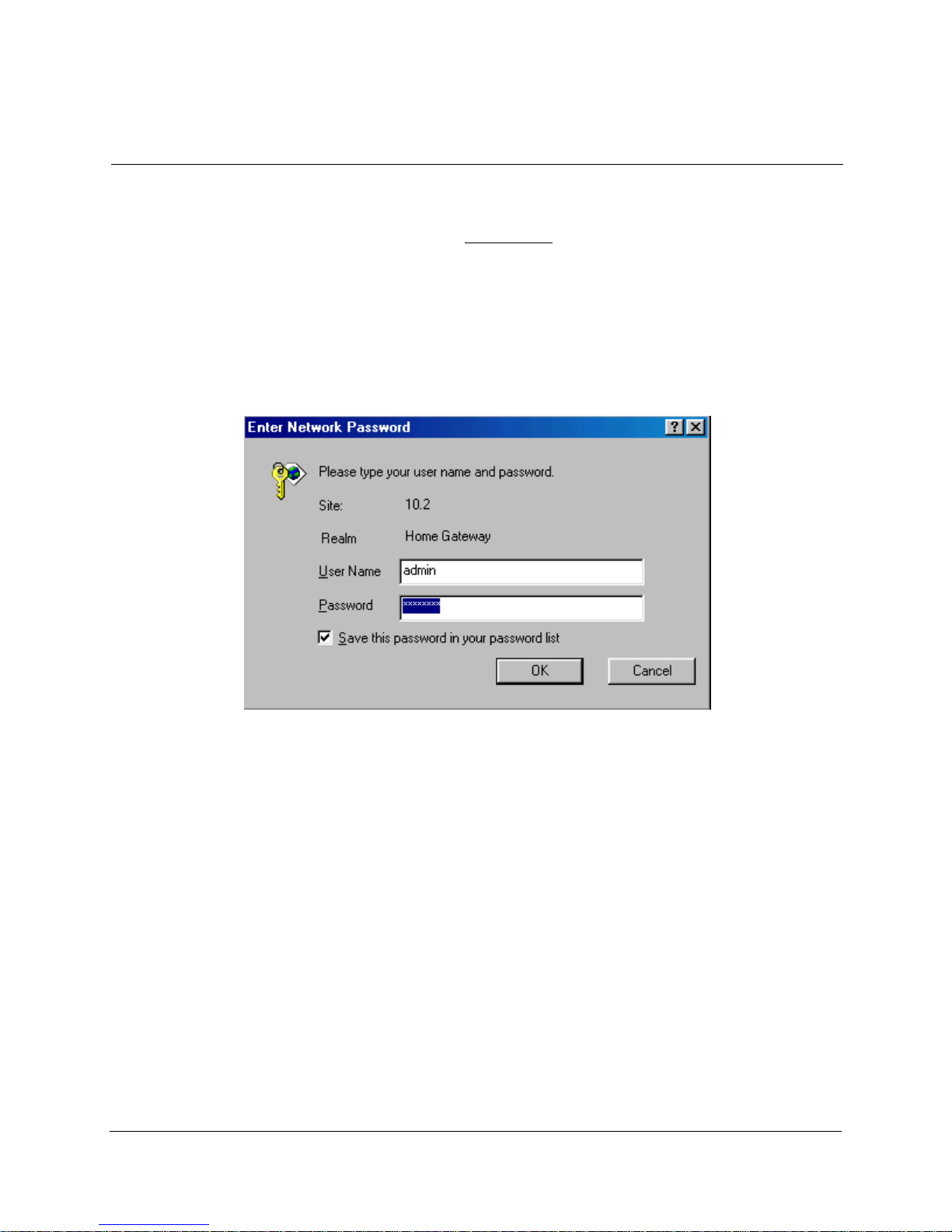
2. Login
1. Launch the Web browser.
2. Enter the LAN port default IP address http://10.0.0.2
3. Entry of the username and password will be prompted. Enter the default login User
Name and Password.
• The default login User Name of the administrator is admin, and the default login
Password is epicrouter.
• The default login User Name for the non-administrator is user, and the default login
Password is password.
2-1
3. Status
The links under the Status column are associated to the pages that represent the status of
system and interfaces.
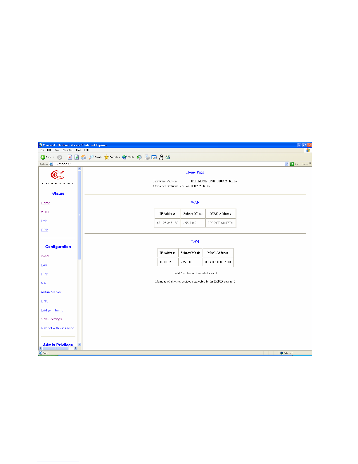
3.1 Home Page
The Home page shows the firmware versions and WAN and LAN interface status.
Firmware Version: This field displays the firmware (vxworks.z) version
number.
3-1

Customer Software Version: This field displays the customer’s own firmware version
number and it is based on revision.txt.
WAN: These fields display the IP address, Subnet Mask and MAC address for the WAN
(ADSL) interface.
LAN: These fields display the IP address, Subnet Mask and MAC address for the LAN
interface.
Total Number of LAN Interfaces: This field displays the total number of available
interfaces for the LAN interface.
Number of Ethernet Devices Connected to the DHCP Server: These fields display the
DHCP client table with the assigned IP addresses and MAC addresses.
3-2

3.2 ADSL Status Page
The ADSL Status page shows the ADSL physical layer status.
Showtime Firmware Version: This field displays the ADSL data pump
firmware version number.
ADSL Line Status: This field displays the ADSL connection process and status.
ADSL Modulation: This field displays the ADSL modulation status for G.dmt or
T1.413.
ADSL Annex Mode: This field displays the ADSL annex modes for Annex A or
Annex B.
ADSL Startup Attempts: This field displays the ADSL connection attempts after loss of
showtime.
ADSL Max Tx Power: This field displays the transmit output power level of the CPE.
ADSL CO Vendor: This field displays the Central Office DSLAM vendor name, if
available.
3-3

Elapsed Time: This field displays the time of the modem has been in operation.
SNR Margin: Amount of increased noise that can be tolerated while maintaining the
designed BER (bit error rate). The SNR Margin is set by Central Office DSLAM. If the
SNR Margin is increased, bit error rate performance will improve, but the data rate will
decrease. Conversely, if the SNR Margin is decreased, bit error rate performance will
decrease, but the data rate will increase.
Line Attenuation: Attenuation is the decrease in magnitude of the ADSL line signal
between the transmitter (Central Office DSLAM) and the receiver (Client ADSL
Modem), measured in dB. It is measured by calculating the difference in dB between the
signal power level received at the Client ADSL modem and the reference signal power
level transmitted from the Central Office DSLAM.
Errored Seconds: The error during Showtime, whenever, a given sec contains CRC
error, that second will be declared error second.
Loss of Signal: This field displays the count of event of ADSL signal loss.
Loss of Frame: This field displays the count of event of ADSL frame loss.
CRC Errors: This field displays the number of transmit data frames containing CRC
errors.
Data Rate: This field displays the ADSL data rate.
Latency: This field displays the latency modes for fast or interleave.
3-4
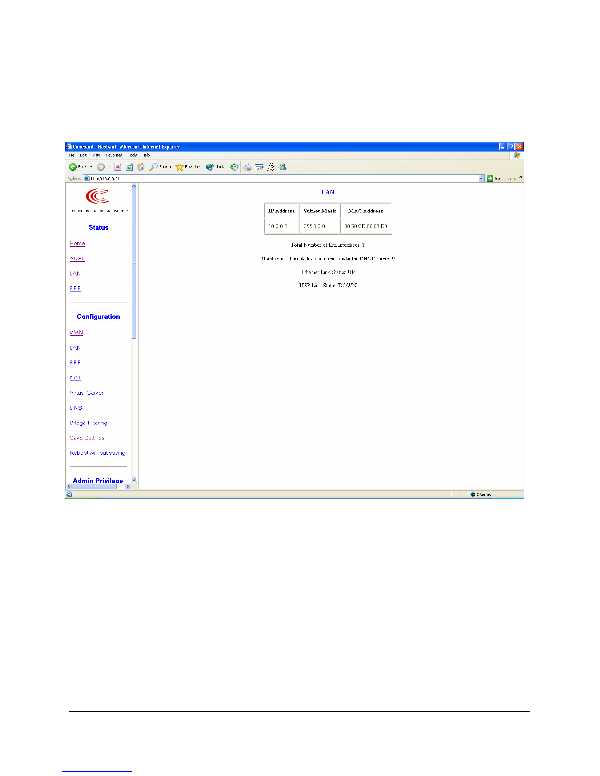
4. LAN Page
The LAN page shows the information and status of LAN port, DHCP client table,
Ethernet link and USB link.
LAN: These fields display the IP address, Subnet Mask and MAC address for the LAN
interface.
Total Number of LAN Interfaces: This field displays the total number of available
interfaces for the LAN interface.
Number of Ethernet Devices Connected to the DHCP Server: These fields display the
DHCP client table with the assigned IP addresses and MAC addresses.
Ethernet Link Status: This field displays the link up or down for the Ethernet.
USB Link Status: This field displays the link up or down for the USB.
4-1
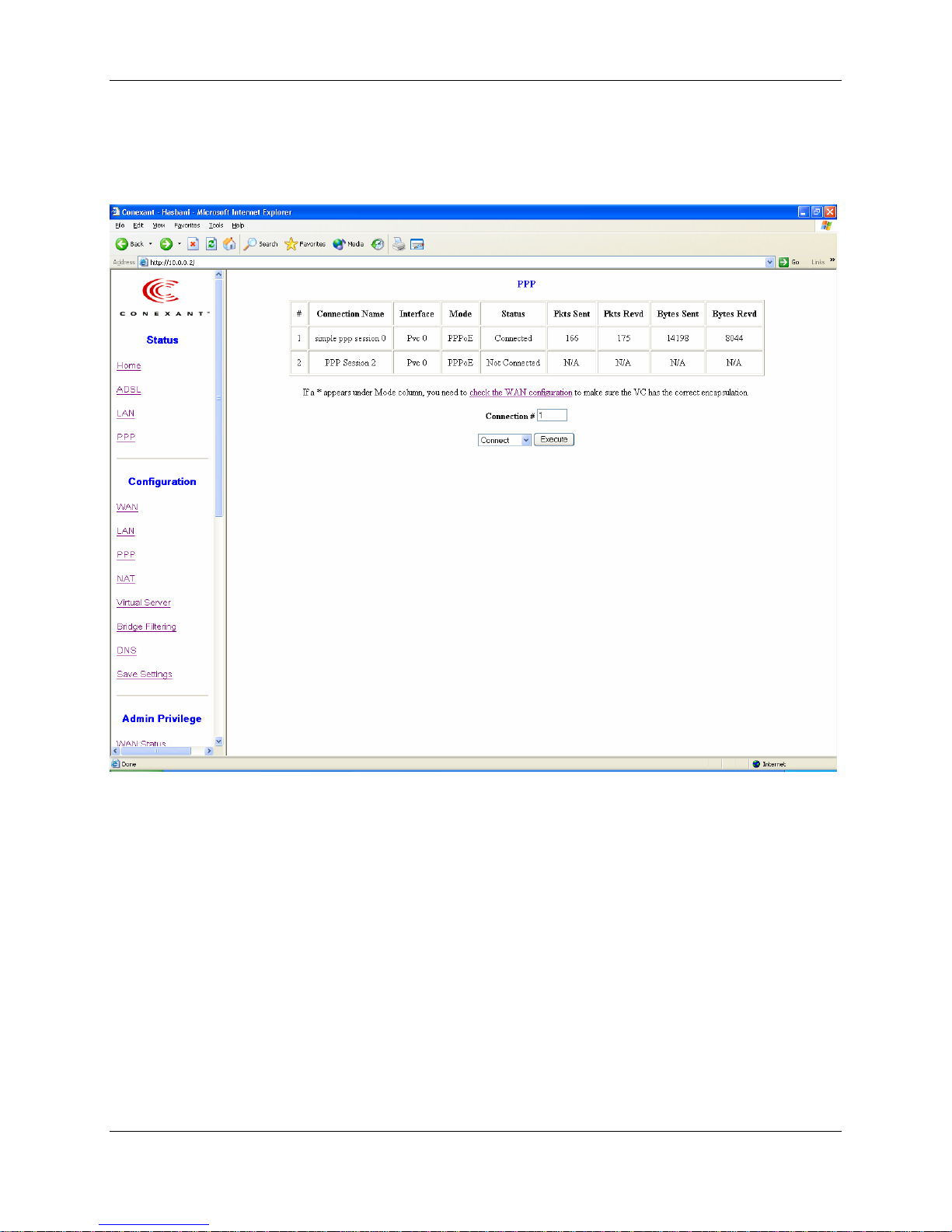
5. PPP Page
The PPP Status page shows the status of PPP for each PPP interface.
PPP: These fields display the Connection Name (user defined), Interface (PVC), Mode
(PPPoE or PPPoA), Status (Connected or Not Connected), Packets Sent, Packets
Received, Bytes Sent and Byte Received.
Connect and Disconnect: This field allows the user to manually connect/disconnect the
PPP connection for each PPP interface. In another word, each PPP session can be
connected and disconnected individually.
5-1
6. Configuration
The links under Configuration column are associated to the pages that represent the
configurations of system and interfaces.
Note: When the configurations are changed, please go to the Save Settings page to
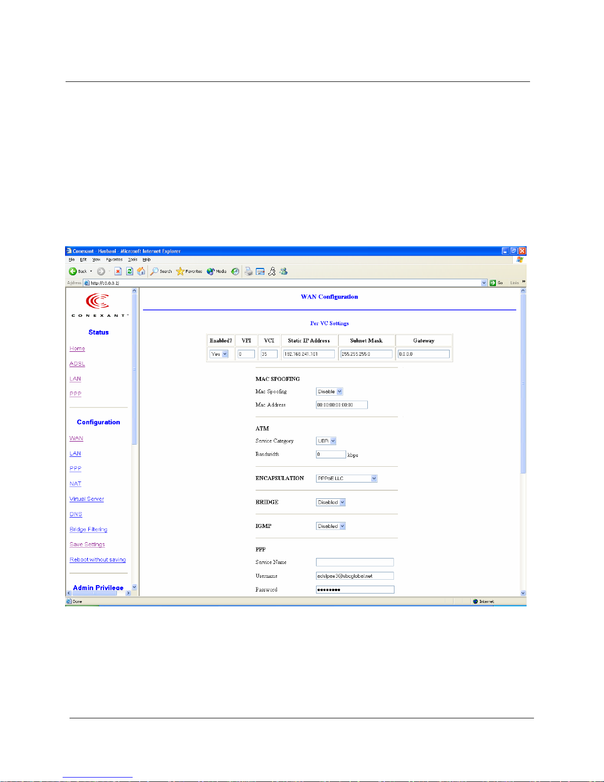
6.1 WAN Configuration
The WAN configuration page allows the user to set the configuration for the
WAN/ADSL ports.
save the new setting and reboot the board.
6-1
6.1.1 Per VC Settings
Under Per VC Setting, it provides the configurations for VPI/VCI, Static IP Address
Subnet Mask, and Gateway. The Static IP Address, Subnet Mask and Gateway are used
for Static IP configuration. Current Conexant firmware supports eight PVCs.
To switch between the PVCs, please choose the options of virtual circuit and click on the
Submit button to switch over.
6-2

6.1.2 MAC Spoofing
The MAC Spoofing is developed to solve the scenario when the ISP only recognizes one
MAC address. Copy the ISP-recognized MAC address here.
6.1.3 ATM
Service Category: UBR and CBR are supported from the ATM.
Bandwidth: Bandwidth setting takes effect only when the CBR is selected. The
maximum available bandwidth is from the upstream data rate of ADSL status page (see
Section 3.2, ADSL ).
6.1.4 Encapsulation, Bridge, PPP, and DHCP Client
Use Table 6-1 to configure a valid setting for each PVC.
Table 6-1. Configuration
WAN Configuration
IP address N/A Automatically assigned by ISP Automatically assigned by ISP Provided by ISP
Subnet Mask N/A Automatically assigned by ISP Automatically assigned by ISP Provided by ISP
Encapsulation 1483 Bridged IP LLC,
Bridge Enabled Disabled Disabled Disabled
PPP Service N/A Provided by ISP N/A N/A
PPP User name N/A Provided by ISP N/A N/A
PPP Password N/A Provided by ISP N/A N/A
DHCP Client enable Unchecked Unchecked Checked Unchecked
Bridge Mode Router Mode (PPPoA/PPPoE)
PPPoA LLC/VC-Mux,
1483 Bridged IP VC-Mux
PPPoE LLC/VC-Mux
Router Mode
(Dynamic IP)
1483 Bridged/Routed IP LLC,
1483 Bridged/Routed VC-Mux,
Classical IP over ATM
Router Mode
(Static IP)
1483 Bridged/Routed IP LLC,
1483 Bridged/Routed VC-Mux,
Classical IP over ATM
6-3

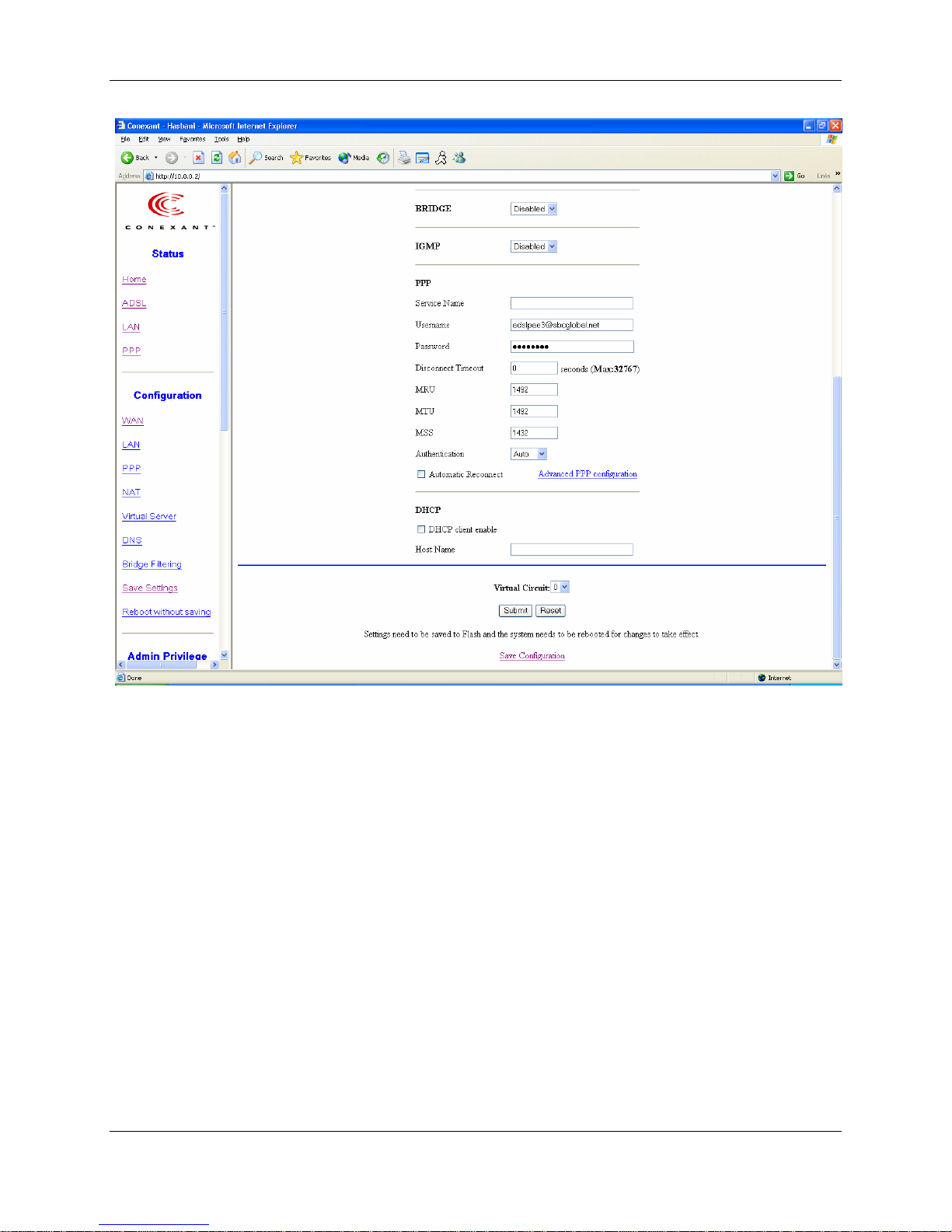
6.1.4.1 PPP Configuration
The current release supports multiple PPP sessions per PVC. The PPP configuration in
the WAN configuration page is for the first PPP session for each PVC. The predefined
PPP Account Name (Account ID) is “Simple PPP Account 0” for PVC0 and predefined
PPP Connection Name is “Simple PPP Session 0” for PVC0. For the other PVC X, the
predefined account name and connection name will be Simple PPP Account X and
Simple PPP Session X. X is the PVC number from 1 to 7.
It can support up to total of 16 PPP sessions, and each PVC can support up to 8 PPP
sessions. The multiple PPP sessions may be configured with any combination over 8
PVCs.
For the multiple PPP sessions, please go to PPP Configuration page (Section 6.3).
Service Name: The service name of PPP is required by some ISPs. If the ISP does not
provide the Service Name, please leave it blank.
Disconnect Timeout: The Disconnect Timeout allows the user to set the specific period
of time to disconnect from the ISP. The default is 0, which means never disconnect from
the ISP.
MRU: Maximum Receive Unit indicates the peer of PPP connection the maximum size
of the PPP information field this device can be received. The default value is 1492 and is
used in the beginning of the PPP negotiation. In the normal negotiation, the peer will
accept this MRU and will not send packet with information field larger than this value.
MTU: Maximum Transmission Unit indicates the network stack of any packet is larger
than this value will be fragmented before the transmission. During the PPP negotiation,
the peer of the PPP connection will indicates its MRU and will be accepted. The actual
MTU of the PPP connection will be set to the smaller one of MTU and the peer’s MRU.
The default is value 1492.
MSS: Maximum Segment Size is the largest size of data that TCP will send in a single IP
packet. When a connection is established between a LAN client and a host in the WAN
side, the LAN client and the WAN host will indicate their MSS during the TCP
connection handshake. The default value is 1432.
Automatic Reconnect: When it is checked, it will maintain the PPP connection all the
time. If the ISP shut down the PPP connection, it will automatically reconnect PPP
session.
Authentication: When AUTO option is chosen, the PAP mode will run first then CHAP.
Host name: Required by some ISPs. If the ISP does not provide the Host name, please
leave it blank.
Q1: If the PPP is disconnected after the Disconnect Timeout and how can I reconnect it?
A: You have to go to the PPP Status under Admin Privileged column, choose the
correct PVC and Connect option, and then click Execute to restart a new PPP secession.
6-4

6.1.5 IGMP
IGMP relay/proxy specification and environment:
Support IGMP proxy/relay function for ADSL modem, based on the following
requirement and case:
On CO side, there must be at least one IGMP querier (router) present. IGMP querier will
send IGMP query packet. The ADSL modem is responsible to relay these IGMP query to
Ethernet.
End-user multicast application device send IGMP report while receiving IGMP query or
being activated by user, the ADSL modem should be responsible to proxy (that is, change
source IP to ADSL modem’s WAN IP) the IGMP report to ADSL WAN side, include all
PVCs. The same case is for IGMP leave packet.
Not necessary to relay multicast routing between two ADSL PVCs or two interfaces in
LAN side.
Special purpose multicast packet (such as RIP 2 packet) should run without interference.
Table 6-2. Packet Process
Rx Entity Packet Class TTL Acti on Notes
ADSL IGMP query 1 Relay to Ethernet
IGMP report 1 Ignore
IGMP leave 1 Ignore
General Multicast IP - Relay it to Ethernet.
Ethernet IGMP query 1 Ignore
IGMP report 1 Relay to all ADSL PVC
IGMP leave 1 Relay to all ADSL PVC
General Multicast IP - Ignore
Note: Before the IGMP mode is enabled; please go to the Miscellaneous
Configuration page to enable the IGMP proxy. Otherwise, the IGMP selection
will not be valid.
Q: Where can I download the free software to test IGMP.
A: Please go to this link http://manimac.itd.nrl.navy.mil/MGEN/.
6-5
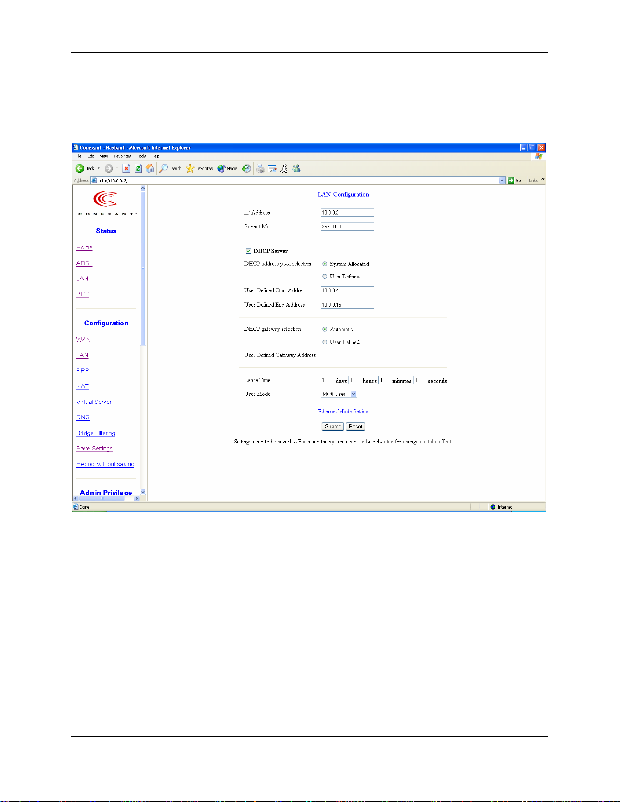
6.2 LAN Configuration
The LAN configuration page allows the user to set the configuration for the LAN port.
LAN IP Address & Subnet Mask: The default is 10.0.0.2 and 255.0.0.0. User can
change it to other private IP address, such as 192.168.1.2, and 255.255.255.0.
DHCP Server
System Allocated: The DHCP address pool is based on LAN port IP address plus 12 IP
addresses. For example, the LAN IP address is 10.0.0.2; the DHCP address pool is at the
range of 10.0.0.3 to 10.0.0.14.
User Defined: The DHCP address pool is at the range of User Defined Start Address
and User Defined End Address. The maximum pool size can be 253 IP addresses: 255
total IP addresses – 1 broadcast address – 1 LAN port IP address.
DHCP Gateway Selection: The default setting for the DHCP Gateway Selection is
“Automatic”. The user can select the “User Defined” to specify “User Defined Gateway
6-6
Address”. The DHCP server will issue the “User Defined Gateway Address” to the
LAN DHCP clients.
Lease time: The Lease time is the amount of time of a network user will be allowed to
connect with DHCP server. If all fields are 0, the allocated IP addresses will be effective
forever.
User mode: Under the Single User mode, the DHCP server only allocates one IP address
to local PC. Under the Multiple User mode, the DHCP server allocates the IP addresses
specified bye the DHCP address pool.
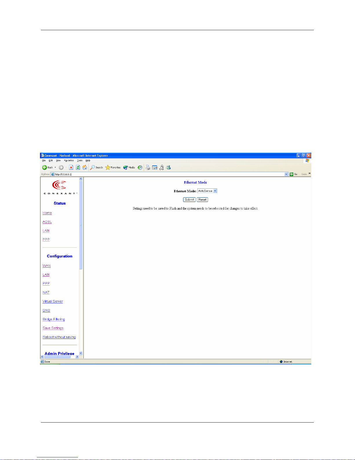
6.2.1 Ethernet Mode Setting
The Ethernet Mode configuration page allows the user to set the LAN port into Auto
Sense, 100 Mbps Full Duplex, 100 Mbps Half Duplex, 10 Mbps Full Duplex or 10 Mbps
Half Duplex.
6-7
 Loading...