


CONTENTS
1. PRODUCT GENERAL INFORMATION..……………………………………………..….2
1.1. Product Description…………………………………………………………………………………….2
1.2. Special Features Highlights……………………………………………………………………………….2
1.3. Product Feature…………………………………………...……………………………………………2
1.4. Product Application………………………………………………………….……………………………..2
2. PRODUCT GENERAL………………………………………………………………….….3
2.1. General Specifications………………………….………………..…………………………..… 3
2.2. LED Indicator………………………………………………………..…………..….………………3
2.3. Interface………………………………………………………….…….………………………..…..3
3. PRODUCT HARDWARE SPECIFICATION……………………….………………….….3
3.1. RF Specification…………………………………………………….………….….…………………..….3
3.2. Hardware Specification………………………………………………………….………………….4
4. PRODUCT SOFTWARE SPECIFICATION………………………………….……...……4
4.1. General Function…………….……………………………...……………..……………………..…..4
4.2. Configuration Function…………..…………………………….………..………………………..….5
5. REGULATION COMPLIANCE…………………………………………………………….5
6. ENVIRONMENTAL REQUIREMENT.…………………………………………..……..5
6.1. Drop and Vibration Test………….……………………….……………………………...……….5
6.2. Operation Environment….……………………………………………………………...……….…6
7. INSTALLATION AND CONFIGURATION……………………..………………..…….6
7.1. Access Point Utility Installation and Configuration………….……………………………...………6
7.2. Access Point Web Configuration…………………………………………………………...………10
1

WIRELESS ACCESS POINT
1. Product General Information
1.1. Product Description
The Access Point is fully compatible with the IEEE 802.11b wireless standard and based on the Direct
Sequence Spread Spectrum Technology, additional with the Modulation Method Packet Binary
Convolutional Code (PBCC) to provide a data rate up to 22Mbps. It supports IEEE 802.3 10BaseT and 100
BaseTX port for easy interfacing to Ethernet backbone. Web page based configuration utility combined with
excellent level of security to provide robustness and roaming features required for personal, SOHO and
enterprise solution. It is a key component for building up a wireless network that connects the wired
networks.
1.2 Special Features Highlights:
High-Speed wireless connection up to 22 Mbps
WEP Encryption function ,up to 256 Bits
Power Saving operation mode
DHCP Server (Option)
DHCP Client
3 operating mode available: Access Point, AP Client and Bridge (Point-to-Point,
Point-to-Multi-point)
1.3 Product Feature
● IEEE 802.11b Direct Sequence high data rate compatible
● Extra modulation type, Packet Binary Convolutional Code (PBCC)
● High-Speed wireless connection, up to 22Mbps format
● Advanced Power Management supports power saving mode for workstations
● Auto fallback data rate in the environment of interference
● WEP Encryption function (64/128/256 Bits hardware supported)
● External two fixed dipole antennas for diversity function
● Plug-and-Play installation
1.4 Product Application
● Home networking for device sharing, Wireless Multimedia
● Wireless office for extension Ethernet range
● Wireless building to building data communication
● Build system in Infrastructure mode
● Suitable in application for
- difficult-to-wired environments
2

- temporary LANs for special projects or peak time like in trade exhibition, meeting...etc.
- frequently changing environments
- SOHO (Small Office and Home Office)
- remote access to corporate network infrastructure
2. PRODUCT GENERAL
2.1. General Specifications
Standards: IEEE802.11b Compliant
Data Rate: 1/2/5.5/11/22 Mbps
Security: Wired Equivalent Privacy (WEP) 64/128/256 Bits
Dimension 140 x 90 x 40 mm
2.2. LED Indicators
Symbol Functions
---------------------------------------------------------------------------------------------------
Power/Status Red for power on
Wireless Green
Ethernet Green
2.3. Interface
RJ-45 10-100 Base-T
Power Jack 2.5 mm
3. PRODUCT HARDWARE SPECIFICATIONS
3.1. RF Specification
3.1.1 General
Emission Type Direct Sequence Spread Spectrum (DSSS)
RF Frequency 2400MHz – 2497 MHz – Japan Band
2400MHz – 2472MHz – North America
2400MHz – 2483.5MHz – Europe
2446.5MHz – 2483.5MHz – France
Operating Channel 11 Channels (US, Canada)
13 Channels (Europe)
14 Channels (Japan)
Radio Chipset: RFMD
Media Access Protocol CSMA/CA (Collision Avoidance) with ACK
3

3.1.2 Transmitter
RF Output Power 16 ~ 18 dBm (40~63 mW)
Frequency Stability Within +
Data modulation type BPSK (1Mbps) / QPSK (2Mpbs) / CCK (5.5/11Mbps) / PBCC
(5.5/11/22 Mbps)
25 ppm
3.1.3 Receiver
Sensitivity 22MHz PBCC - 80 dBm (Typically @25℃+5℃)
11MHz PBCC - 85 dBm (Typically @25℃+
11MHz CCK - 82 dBm (Typically @25℃+
5℃)
5℃)
3.1.4 Antenna Type
Antenna Type Dual Dipole Antenna with Diversity
Antenna Gain 2 dBi (Typically).
3.1.5. Power Consumption
Operation max. 1.2 A
Standby 600mA +
50mA
3.2. Hardware Specification
3.2.1. CPU
Processor SAMSUNG ARM7 CPU
3.2.2. Memory
SDRAM 8 MBytes
Flash 1 MBytes
3.2.2 Power Adapter
Power Voltage DC 5 Volt + 5%, AC Adapter AC 100V-240V
4. PRODUCT SOFTWARE SPECIFICATION
4.1. General Function
a) Standard : IEEE 802.11b/IEEE 802.3
b) RTS/CTS Handshake
c) Duplicate detection and recovery
d) Wired Equivalent Privacy Algorithm (WEP) 64/128/256 Bits
e) Distributed Coordination Function: CSMA/CA, Back of Procedure, ACK Procedure, Retransmission
of unacknowledged frames
f) Authentication Algorithm
4

g) Fragment / De-fragment
h) Preamble Long / Short
i) Roaming Function
j) Power Saving Management
k) Beacon Generation
l) Access Control
m) HTTPD/DHCP Client
n) Filtering function
o) Bridge Mode for Building to Building Transmission
p) AP Client Mode
q) DHCP Server (Option)
r) DHCP Client
s) Finger print security feature (Option)
4.2. Configuration Function
4.2.1. Interface
a) Web Configuration
b) Windows Configuration Utility
5. REGULATION COMPLIANCE
Compliant with
FCC Part 15 Class B, Sec. 15.247 and 15.109
ETS 300 328, ETS 300 826, EN60950 and CE-Mark
Telec (Japan), VCCI (Option)
WiFi Compliant
6. ENVIRONMENTAL REQUIREMENT
6.1. Drop and Vibration
6.1.1. Anti-Static Voltage
Static voltage tests by 4kV in body should not cause system fail.
6.1.2. Vibration Test
The vibration test is under the Frequency and amplitude 10~25 1mm in vertical and horizontal
direction by 30 minutes that should not cause any damage on product.
6.1.3. Package Drop Test
Dropping the package from the height of 50cm for each of the six(6) faces onto the hard-wood
floor will not cause any product damage.
5
6.2. Usage Condition
6.2.1. Temperature Range
Operating: -0℃ - +55℃ (Except RF output power and sensitivity)
Storage: -20 ℃ - +70℃
6.2.2. Temperature Shock
The one cycle of reliability test is keeping -30℃ for 2 hours, switching temperature up to +60 ℃
within one hour, and testing at +60℃ by 2 hours, and switching temperature to -30℃ within one
hour. Three cycle should be tested and without any product fail.
6.2.3. Humidity
Operating: 0% to 70%
Storage 0% to 95% Non-condensing
7. INSTALLATION AND CONFIGURATION
7.1 Access Point Utility Installation and Configuration
7.1.1 Utility Installation
1. Start the computer
2. Insert the CD into CD-ROM
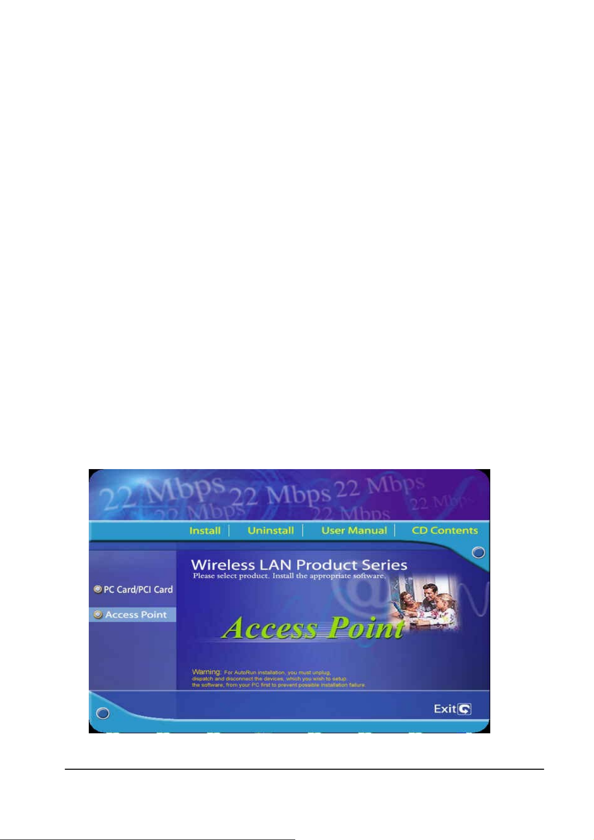
3. Windows will automatically start Installshield Wizard or run “E:\22M.exe” then following screen
will appear.
6

4. Select “Access Point”
6. Click “Install “ Button.
7. Click “Next” button.
8. Click “Finish” button to restart computer.
7.1.2 Utility Configuration
Please Click following icon in the screen.
Caution: If you select one or more Access points, then click Apply in following screens. One or
more user names and passwords prompt will appear. Type in “admin” as the user name and
“admin” as the password. Click Ok.
7

Link inf.
The Link inf. screen will appear. You can view the current status and settings. Then, click AP settings.
AP Settings
The AP setting screen will now appear. Enter a unique name access point for the Access Point and your wireless
network’s SSID, select the channel at which the network broadband its wireless signal. Then, click Advanced
Settings.
8

Advanced Setup
On this page, you can set the AP mode plus following settings:
Beacon Interval – By default, it is set to 100mps.
RTS Threshold – By default, it is set to 2432. The value should remain on its default setting 2432 bytes. If you
encounter any date flow, only minor modifications are recommended.
Fragmentation Threshold – By default, it is set to 2346. The value indicates how much of the network
resources devoted to recovering packet errors. The value should remain at its default setting of 2432 bytes. If
you have decreased this value and experience high packet error rates, you can increase it again, but will likely
decrease overall network performance.
DTIM Interval – shows the client how often the beacon contains a delivery traffic indication message. Input
range is from 1 to 65535. By default, it is set to 3.
TX Rates – You may select 1. 1-2mbps. 2. 1-2-5.5-11mbps. 3. 1-2-5.5-11-22mbps.
Preamble Type -- There is the “Long” or “Short” selection to ensure that systems receiving the information
correctly interpret when the data transmission starts. To select “Short” Preamble may be used to minimize
overhead and “Long” to maximize the network data throughput. The default value will be set for “Long”.
Authentication Type – You may select Open System or Shared Key. By default, it is set to Both.
Antenna Selection – Choices are 1.Left Antenna 2. Right Antenna 3. Diversity Antenna. By default, it is set to
Auto Select.
9

IP Setting
The IP Setting screen will appear. Unless your network has a DHCP server, you will want to turn on the bottom
of DHCP server. Enter an IP address and IP Mask appropriate to your network. Then, Click WEP Settings .
WEP Settings
You will set the Wired Equivalent Privacy (WEP) encryption for your wired network. Select a WEP
configuration method and a passphrase. Then, click Apply to finish WEP settings.
10

7.2. Access Point Web Configuration
7.2.1 Web Configuration
1. It can be configured using the web browser from Windows
®
98/2000/ME/XP. You need to start your web browser
and type http://192.168.1.1
2. A user name and password prompt will appear. Type in “admin” as the user name and “admin” as the password.
Click Ok.
in the address box. This number is the default IP address of your Access Point.
11

Status
You can view the current status and settings.
Click View Log. The View Log screen will appear. You can view the log status. You can clear or refresh the
log record.
12

Basic Setting
Click Basic Setting. The basic setting screen will now appear. Enter a unique name access point for the Access
Point and your wireless network’s SSID, select the channel at which the network broadband its wireless signal.
You will set the Wired Equivalent Privacy (WEP) encryption for your wired network. Select a WEP
configuration method and a passphrase. Then, click Apply to finish setting.
IP Setting
Click IP Setting. The IP Setting screen will appear. Unless your network has a DHCP server, you will want to
turn on the bottom of DHCP server. Enter an IP address and IP Mask appropriate to your network. Then, click
the Advanced Setting.
13

Advanced Setup
On this page, you can set the AP mode plus following settings:
Beacon Interval – By default, it is set to 100mps.
RTS Threshold – By default, it is set to 2432. The value should remain on its default setting 2432 bytes. If
you encounter any date flow, only minor modifications are recommended.
Fragmentation Threshold – By default, it is set to 2346. The value indicates how much of the network
resources devoted to recovering packet errors. The value should remain at its default setting of 2432 bytes. If
you have decreased this value and experience high packet error rates, you can increase it again, but will likely
decrease overall network performance.
DTIM Interval – shows the client how often the beacon contains a delivery traffic indication message. Input
range is from 1 to 65535. By default, it is set to 3.
TX Rates – You may select 1. 1-2mbps. 2. 1-2-5.5-11mbps. 3. 1-2-5.5-11-22mbps.
Preamble Type -- There is the “Long” or “Short” selection to ensure that systems receiving the information
correctly interpret when the data transmission starts. To select “Short” Preamble may be used to minimize
overhead and “Long” to maximize the network data throughput. The default value will be set for “Long”.
Authentication Type – You may select Open System or Shared Key. By default, it is set to Both.
Antenna Selection – Choices are 1.Left Antenna 2. Right Antenna 3. Diversity Antenna.
By default, it is set to Auto Select.
14

Security
Click Security. You may reset the password in this page. Click Apply when complete. Then, Click Tools.
15

Tools
The Tools screen will appear. You may also perform the backup and restore your personal settings. When you
click on “backup” it will prompt you a location to save the “config.bin” file. When you try to restore the
settings you have saved, click “Browse” to locate the file and perform the restore procedure. You upgrade
your firmware in this page.
16

Federal Communication Commission Interference Statement
This equipment has been tested and found to comply with the limits for a Class B digital device, pursuant to Part 15 of the FCC
Rules. These limits are designed to provide reasonable protection against harmful interference in a residential installation. This
equipment generates, uses and can radiate radio frequency energy and, if t not installed and used in accordance with the
instructions, may cause harmful interference to radio communications. However, there is no guarantee that interference will not
occur in a particular installation. If this equipment does cause harmful interference to radio or television reception, which can be
determined by during the equipment off and on, the user is encouraged to try to correct the interference by one or more of the
following measures:
Reorient or relocate the receiving antenna.
Increase the separation between the equipment and receiver.
Connect the equipment to an outlet on a circuit different from that to which the receiver is connected.
Consult the dealer or an experienced radio/TV technician for help.
This device complies with Part 15 of the FCC rules. Operation is subject to the following two conditions: (1) This device may not
cause harmful interference, and (2) this device must accept any interference received, including interference that may cause
undesired operation.
IMPORTANT NOTE:
FCC Radiation Exposure Statement
This equipment complies with FCC radiation exposure limits set forth for an uncontrolled environment. This equipment should be
installed and operated with minimum distance 20cm between the radiator and your body.
This transmitter must not be co-located or operating in conjunction with any other antenna or transmitter.
Caution: This device includes an module which can emit RF exposure rule, the user has to keep at 20cm separation distance
between the radiator and the body of the user.
Printed in Taiwan
17
 Loading...