

Page 1

880022..1111gg W
Wiirreelleessss LLAANN
UUSSBB AAddaapptteerr
User Manual
Version: 2.0
(August, 2004)
Miinnii
M
Page 2

COPYRIGHT
Copyright © 2004/2005 by this company. All rights reserved. No part of this
publication may be reproduced, transmitted, transcribed, stored in a retrieval
system, or translated into any language or computer language, in any form or
by any means, electronic, mechanical, magnetic, optical, chemical, manual or
otherwise, without the prior written permission of this company
This company makes no representations or warranties, either expressed or
implied, with respect to the contents hereof and specifically disclaims any
warranties, merchantability or fitness for any particular purpose. Any software
described in this manual is sold or licensed "as is". Should the programs
prove defective following their purchase, the buyer (and not this company, its
distributor, or its dealer) assumes the entire cost of all necessary servicing,
repair, and any incidental or consequential damages resulting from any defect
in the software. Further, this company reserves the right to revise this
publication and to make changes from time to time in the contents hereof
without obligation to notify any person of such revision or changes.
All brand and produc t nam es mentione d in this manua l are tra demark s and/or re gistere d
trademarks of their res pective holders.
Page 3

Federal Communication Commission
Interference Statem ent
This equipment has been tested and found to comply with the limits for a
Class B digital device, pursuant to Part 15 of FCC Rules. These limits are
designed to provide reasonable protection against harmful interference in a
residential installation. This equipment generates, uses, and can radiate radio
frequency energy and, if not installed and used in accordance with the
instructions, may cause harmful interference to radio communications.
However, there is no guarantee that interference will not occur in a particular
installation. If this equipment does cause harmful interference to radio or
television reception, which can be determined by turning the equipment off
and on, the user is encouraged to try to correct the interference by one or
more of the following measures:
1. Reorient or relocate the receiving antenna.
2. Increase the separation between the equipment and receiver.
3. Connect the equipment into an outlet on a circuit different from that to which the
receiver is connected.
4. Consult the dealer or an experienced radio technician for help.
FCC Caution
This equipment must be installed and operated in accordance with provided
instructions and a minimum 5 cm spacing must be provided between
computer mounted antenna and person’s body (excluding extremities of
hands, wrist and feet) during wireless modes of operation.
This device complies with Part 15 of the FCC Rules. Operation is subject to
the following two conditions: (1) this device may not cause harmful
interference, and (2) this device must accept any interference received,
including interference that may cause undesired operation.
Any changes or modifications not expressly approved by the party responsible
for compliance could void the authority to operate equipment.
Federal Communication Commission (FCC) Radiation Exposure Statement
This equipment complies with FCC radiation exposure set forth for an
uncontrolled environment. In order to avoid the possibility of exceeding the
FCC radio frequency exposure limits, human proximity to the antenna shall
not be less than 20cm (8 inches) during normal operation.
Page 4

R&TTE Compliance Statement
This equipment complies with all the requirements of DIRECTIVE 1999/5/CE
OF THE EUROPEAN PARLIAMENT AND THE COUNCIL of March 9, 1999 on
radio equipment and telecommunication terminal Equipment and the mutual
recognition of their conformity (R&TTE)
The R&TTE Directive repeals and replaces in the directive 98/13/EEC
(Telecommunications Terminal Equipment and Satellite Earth Station
Equipment) As of April 8, 2000.
Safety
This equipment is designed with the utmost care for the safety of those who
install and use it. However, special attention must be paid to the dangers of
electric shock and static electricity when working with electrical equipment. All
guidelines of this and of the computer manufacture must therefore be allowed
at all times to ensure the safe use of the equipment.
EU Countries Intended for Use
The ETSI version of this device is intended for home and office use in Austria,
Belgium, Denmark, Finland, France, Germany, Greece, Ireland, Italy,
Luxembourg, the Netherlands, Portugal, Spain, Sweden, and the United
Kingdom.
The ETSI version of this device is also authorized for use in EFTA member
states: Iceland, Liechtenstein, Norway, and Switzerland.
EU Countries Not intended for use
None.
Page 5

CONTENTS
1 INTRODUCTION.............................................................................1
1.1 F
1.2 S
1.3 P
EATURES
PECIFICATIONS
ACKAGE CONTENTS
.................................................................................................... 1
............................................................................................ 1
..................................................................................... 2
2 INSTALLATION PROCEDURE .....................................................3
3 CONFIGURATION UTILITY .........................................................9
3.1 W
3.2 G
IRELESS CONNECTION STATUS
ENERAL CONNECTION SETTING
.................................................................... 9
................................................................. 11
3.3 WEP
3.3.1 WEP Setting ........................................................................................................... 15
3.3.2 WPA Setting .......................................................................................................... 16
3.4 A
3.5 S
DVANCED SETTING
OFTWARE
3.5.1 AP Connection Status............................................................................................. 19
3.5.2 AP General Connection Setting............................................................................... 20
3.5.3 MAC Address Filter................................................................................................ 22
AND
WPA E
AP M
NCRYPTION
...................................................................... 14
................................................................................... 18
.................................................................................. 19
ODE
4 TROUBLESHOOTING..................................................................24
Page 6

1 Introduction
Thank you for purch asing the 802.11 g Wireless LAN Mini USB Adapter . This USB Adapt er is
designed to comply with IEEE 802.11g Wireless LAN standard and easy to carry with the
Mini size. It is suitab le for any Lapt op or Desk top com puters.
This adapter supports 64/128/ 256-bit W EP data encrypt ion that pr otects your wir eless
network from eavesdro pping. I t also su pports W PA (W i-Fi Protec ted Ac cess) feat ure that
combines IEEE 80 2.1x and TKIP (T emporal Key Inte grity Protoc ol) technolo gies. Client
users are req uired to a uthorize before acc essing to APs or AP Router s, and the data
transmitted i n the net work is encrypted /decrypt ed by a d ynamicall y changed s ecret k ey.
This adapter has built- in AES engine which ens ure the highest degree of securit y and
authenticit y for digi tal inf ormatio n and it is the m ost adv anced so lution def ined b y IEEE
802.11i for the security in the wireless network.
This adapter is cost-ef fective , together with th e versat ile featur es; it is the bes t soluti on for
you to build your wire less network .
1.1 Features
•
Complies with the IEEE 802.11b and IEEE 802.11g 2.4GHz standards.
•
Up to 54Mbps high data transfer rate.
•
Support 64/128/256-bit WEP, WPA (TKIP with IEEE 802.1x) and AES functions for high level
of security.
•
Supports Software AP function, which turns the wireless station into a wireless AP.
•
Complies with IEEE 802.11d country roaming standard.
•
Support the most popular operating system: Windows 98SE/Me/2000/XP/Server 2003.
•
Supports USB 2.0/1.1/1.0 interf ac e.
•
Portable and mini-size design.
•
Suitable for Any Notebook or Desktop PC.
1.2 Specifications
•
Standard: IEEE 802.11g/b
•
Bus Type: USB 2.0 Type A
•
Frequency Band: 2.4000~2.4835GHz (Industrial Scientific Medical Band)
•
Modulation: OFDM with BPSK, QPSK, 16QAM, 64QAM (11g)
BPSK, QPSK, CCK (11b)
•
Data Rate: 54/48/36/24/18/12/11/9/6/5.5/2/1Mbps auto fallback
•
Security: 64/128/256-bit WEP Data Encryption, WPA (IEEE 802.1x with TKIP) and AES
•
Antenna: Internal Antenna
•
Drivers: Windows 98SE/Me/2000/XP/Server 2003
•
LED: Link/Activity
1
Page 7

•
Transmit Power: 16dBm (Typical)
•
Dimension: 9(H) x 27(W) x 87(D)
•
Temperature: 32~131°F (0 ~55°C)
•
Humidity: 0-95% (NonCondens in g)
•
Certification: FCC, CE
1.3 Package Contents
Before you be gin the i nstallat ion, ple ase check the item s of your packag e. The pac kage
should include th e followin g items:
•
One USB Adapter
•
One USB 2.0 Extension Cable (100 cm)
•
One Quick Guide
•
One CD (Driver/Utility/Manual)
If any of the above items is mis sing, contact your supplier as soo n as possible.
2
Page 8
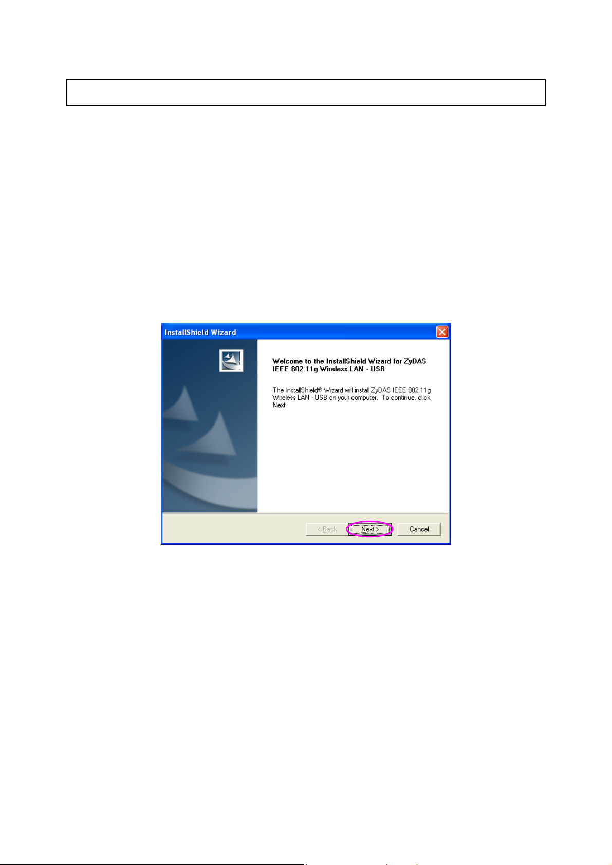
2 Installation Procedure
Before you proce ed with the instal lation, pleas e notice follo wing descript ions.
Note1: Please do not install the USB adapter into your computer before installing the software
program from the CD.
Note2: The following installation was operated in Windows XP. (Procedures are similar for
Windows 98SE/Me/2000/Server 2003.)
Note3: If you have installed the Wireless PC Card driver & utility before, please uninstall the
old version first.
Please follo w belo w instruc tions to install the US B Adapter.
I. Install the Configuration Utility
A. Insert the Installat ion CD to your CD-RO M Drive. Execute th e “setup” program .
B. If you want to install t he sof tware progr am in ano ther loc ation, c lick “ Browser” a nd select
an alternativ e destin ation. T hen, clic k “Next” .
3
Page 9
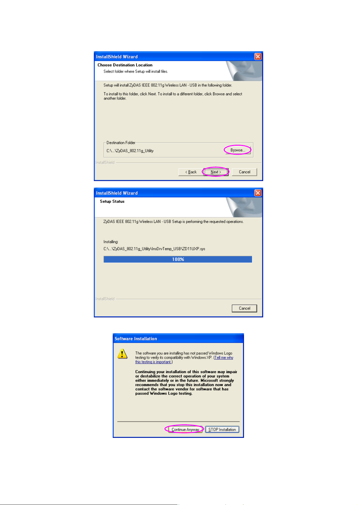
C. Click “Continue Anywa y” to finish the inst allation.
4
Page 10
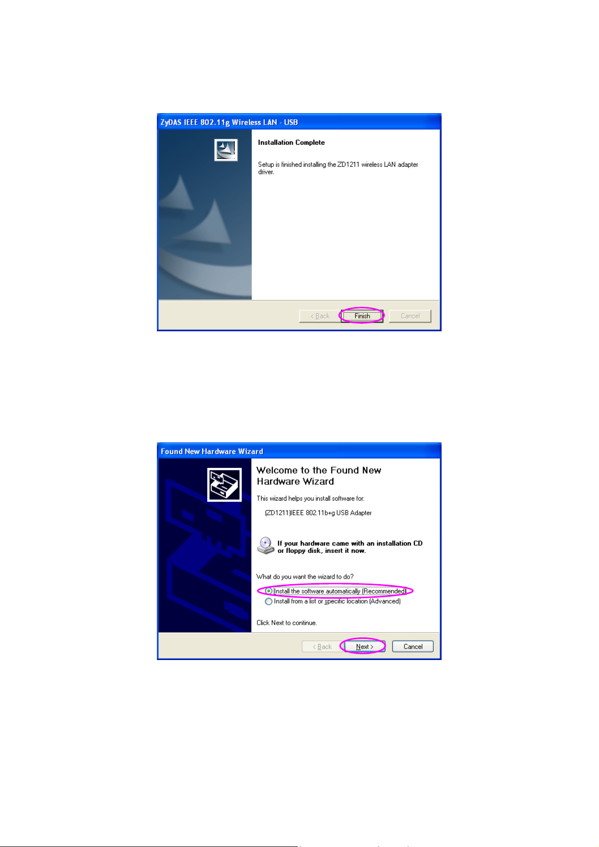
D. Click “Finis h” to com plete t he insta llation .
II. Install the USB Adapter
A. Plug the USB Adapt er into the USB port of your com puter.
B. The “Found New Har dware W izard” is displ ayed, sel ect “Insta ll the s oftwa re autom aticall y
(Recommended) ” and cli ck “Nex t”.
C. Click “Continue Anywa y” and the s ystem wi ll start to insta ll the U SB adapt er.
5
Page 11
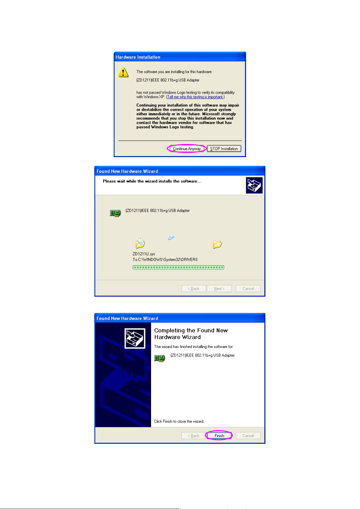
D. Click “Finis h” to com plete t he insta llation .
6
Page 12
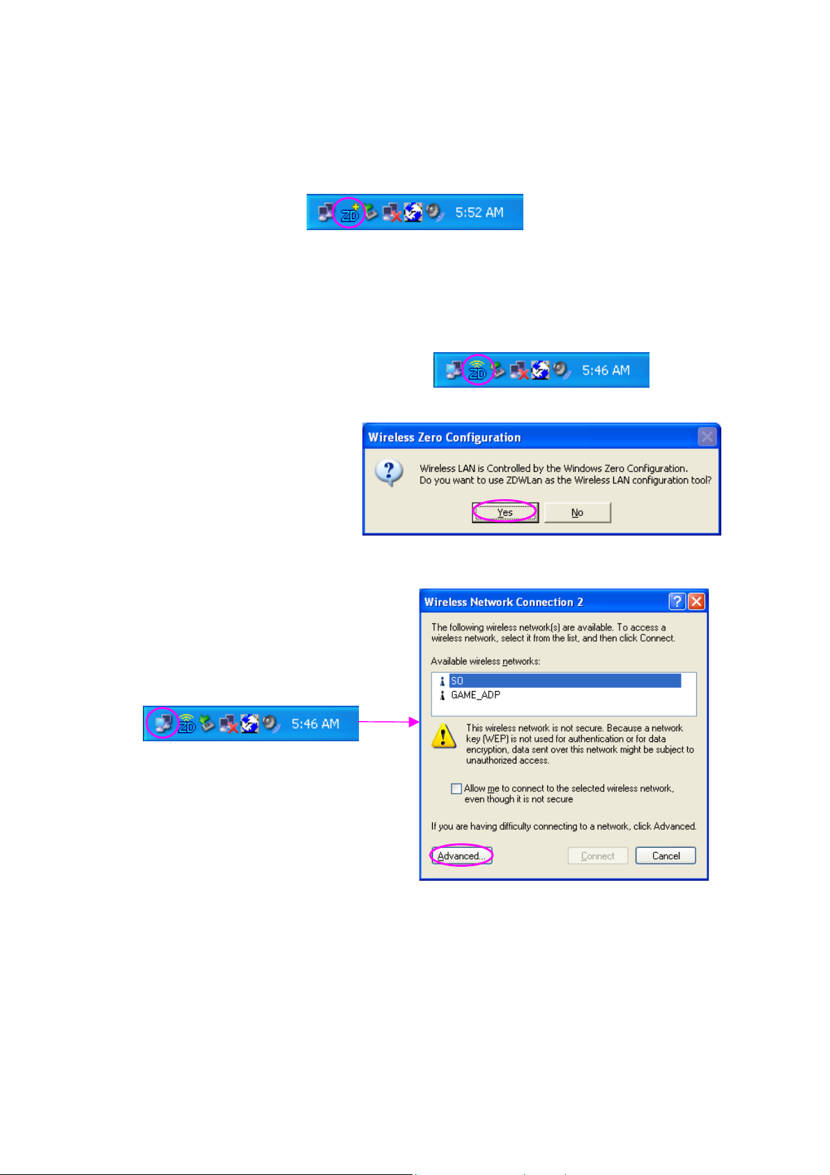
III. Using the Configuration Utilit y
To setup the U SB adapt er, double-c lick th e icon in the s ystem tray.
For Windows X P, there i s a “W indows Zero Configur ation T ool” for you to setu p wireles s
clients. If you want to us e the Ut ility of the USB ada pter, please follow one of the ways as
below.
First Way
A. Double-click the utility
icon in the system tray.
B. Click “Yes” to use the
utility of the USB ad apter.
Second Way
A. Right-click the icon and
select “View Available
Wireless Networks”.
B. Click “Advanced”.
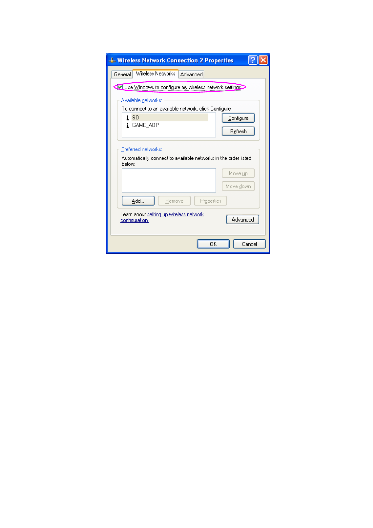
C. Uncheck “Us e Windows t o
configure m y wireles s
network settin gs”.
7
Page 13
8
Page 14

3 Configuration Utility
The Configura tion Uti lity is a powerf ul applic ation that helps you conf igure the 802.1 1g
Wireless LAN Mini US B Adapter and moni tor the link stat us during the co mmunicati on
process.
The Configura tion Uti lity appe ars as an icon on the s ystem tra y of W indows whil e the car d is
running. You can op en it by double-c lick on the ic on.
Right click the icon, t here are s ome item s for you to oper ate the c onfigur ation ut ility.
Open Utilit y Window
Select “Open Utilit y Window” to open t he Confi guratio n Utilit y tool.
Exit ZDW lan
Select “Exit Z DW lan” to close t he Config uration Utility to ol.
Before using the util ity, you have to k now som e restrict ions of the util ity.
1. If you want to connect to 11g (up to 54Mbps) ne twork, pleas e ensure to instal l the
adapter to PC or laptop with USB 2.0 inter face. This adapter runs at lo wer performanc e
while you con nect it t o the US B 1.1/1.0 port of your comput er instea d.
2. This adapter will wor k in 11b mode wh en the network type is in Ad Hoc mode. It is
defines by Wi-Fi organization. If you want to enable the data rate up to 54Mbps (11g),
please follo w steps list ed belo w.
A. Go to “N etwork Connections ”.
B. Right C lick th e “Wir eless Net work Conn ection” a nd selec t “Prop erties”.
C. Fr om the po p-up scree n, click “Config ure”.
D. En ter into “A dvanced” page of the “Proper ties” sc reen.
E. Enable the sett ing of “ IBSS_G _Mode”.
3.1 Wireless Connection Status
When you ope n the Conf igurat ion Utilit y, the system will scan all the ch annels t o find a ll the
access points/stat ions within th e accessible rang e of your card and auto maticall y connect to
the wireless device with the hig hest sign al streng th. From the scree n, you m ay know al l the
information abou t the wireless connection.
9
Page 15
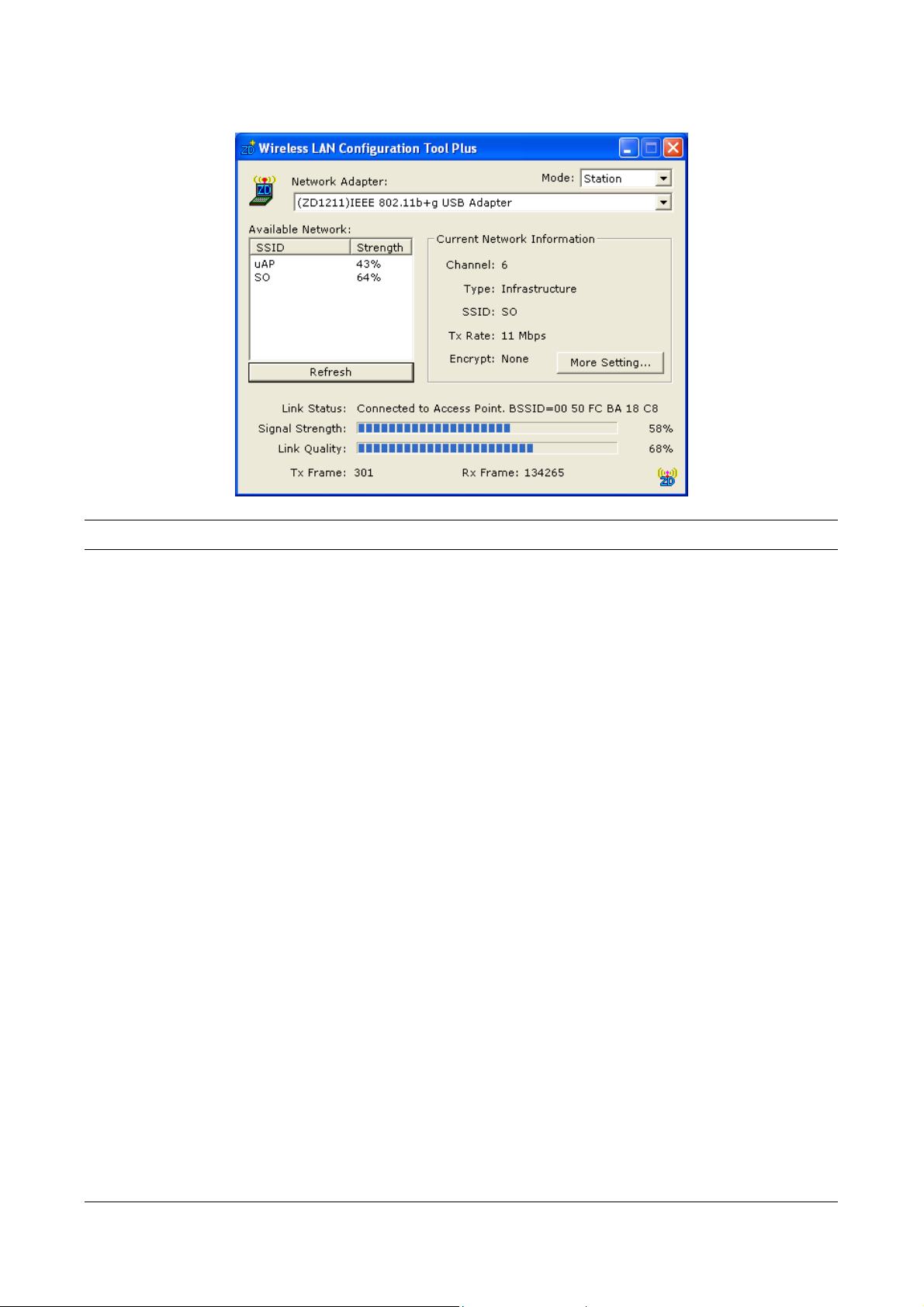
Parameter Description
Mode Station – Set the USB adapter a wireless client.
Access Point – Turns the U SB adapt er to func tion as a wireless
AP. Please refer to Section 3.5 for the AP settings.
Network Adapter Display the product inform ation of the USB Adapt er.
Available Network Display all the SSID and Signal Strength of wireless devices
nearby. To re-survey the available wireless devices please click
“Refresh”.
There are two ways to a utomatic ally mak e the conn ection
between the US B Adapt er and the wireless devic e on the list.
1. Double-click the wireless device on the list directly.
2. Selec t the d evice you inten d to conn ect and th en click
“Connect this site“.
Current Network Inf ormation Display the inform ation about the wir eless netw ork this adapt er is
connecting to. The inf ormation includes Channel , Type, S SID, TX
Rate and Encrypt sett ings. Note: Pl ease refer to Sect ion 3.2 for
the description of each item .
More Setting For setting m ore funct ions incl uding d isable/ena ble W EP and
Power Saving Mode, etc. Please refer to Section 3.2, 3.3 and 3.4.
Link Status Display the s tatus of the wirel ess connec tion.
BSSID Display the M AC Addres s of the net work the a dapter is
connecting to.
10
Page 16
Parameter Description
Signal Streng th This bar sho ws the si gnal str ength le vel. T he higher p ercenta ge
shown in the bar, the m ore ra dio signa l been rec eived b y the
adapter. This in dicator helps to find the proper p osition of the
adapter for qualit y network operation.
Link Quality This bar indic ates the qualit y of the l ink. The h igher the
percentage, the bet ter the qualit y.
TX Frame It shows the num ber of data fram es whic h are tra nsmitted b y the
adapter succ essfull y.
RX Frame It shows the num ber of data fram es whic h are recei ved b y the
adapter succ essfull y.
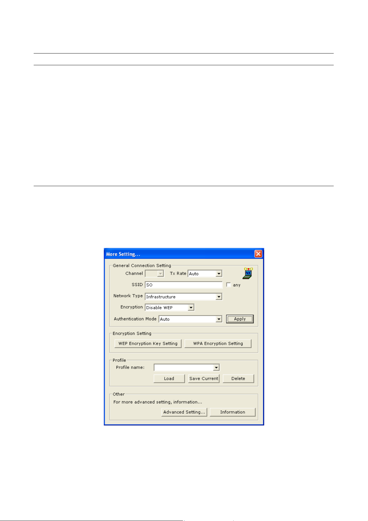
3.2 General Connection Setting
Click “More S etting”, us ers are allowed to setup t he wireles s connec tion sett ing, Enc ryption
Setting of the USB adapter and other advanced functions.
11
Page 17

Parameter Description
General Con nection Setting
Channel Select the n umber of the radio channe l used f or the net working.
The channel set ting of t he wire less dev ices with in a net work
should be the s ame.
Tx Rate There are severa l options includin g
Auto/1/2/5.5/1 1/6/9/12/ 18/24/36 /48/54Mbps for you to se lect.
When the “Auto” is sel ected, t he devic e will cho ose the m ost
suitable trans missio n rate aut omatica lly. The higher data rate you
designated in the net work, the s horter distanc e is a llowed
between the adapter an d the wireless dev ices.
When the adap ter work s in 11b m ode, the m aximum data rat e is
11Mbps so that there are only “Auto/1/2 /5.5/11Mbps ” options you
can select.
SSID The SSID (up to 32 print able ASCII c haracters ) is the u nique
name identifie d in a WLAN. The ID pre vents the uninte ntional
merging of t wo co-loc ated W LANs.
You may specify a SSID for the adapter and then only the device
with the same SSID can in terconnect to th e adapter.
Any If “Any“ check box is en abled, the adapter will sur vey and con nect
to one of the available wireless devices without check ing the
consistenc y of channel and SSI D with the wireles s device.
Network T ype Ad- H o c – T his m ode enab les wirel ess netw ork ada pters
interconnect ing without t hrough AP or Rout er. Select this mode if
there is no AP or Router in the network.
Infrastructure – This operat ion mode requir es the pr esence of an
802.11 Access Point. All communication is done via the Access
Point or Router.
Encryption If you want to encrypt the data transmitted or received in the
network, select one of th e encrypt ion wa ys from the pu ll-down l ist.
Disable – Disable encrypt ion funct ion.
WEP – Enable the W EP Data Encr yption. W hen the item is
selected, you have to c ontinue s etting the W EP Encr yption ke ys.
TKIP – TKIP (Temporal Ke y Integrit y Protoc ol) cha nges the
temporal ke y every 10,0 00 packets . This i nsures much gre ater
security. than the standard WEP security.
12
Page 18

Parameter Description
Encr yption AES – AES has bee n developed to ensure the highest de gree of
security and authenticity for digital information and it is the most
advanced solution defined by IEEE 802.11i for the security in the
wireless network.
Note: All devices in th e network should us e the same encr yption
method to ensure the c ommunicati on.
Authenticati on Mode This setting has to b e consist ent with t he wire less net works th at
the adapter intends to connect.
Open System – No authentication is needed among the wireless
network.
Shared Key – Only wireless devices usin g a shared k ey (W EP
Key identifie d) are al lowed to connec t each other .
Auto – Auto switc h the a uthentic ation algor ithm depending on the
wireless netw orks that the ada pter is c onnecting to.
WPA – This mode is for enterpr ise with an aut henticatio n server
(Radius Server) , a Certificat e Server, W PA-enabled acc ess
poin/router, and a W PA-enab led wire less st ation. Once W PA is
enabled, all s tations and acces s poin ts on the network must be
WPA-enabled in order to acces s the n etwork . WPA m ode onl y
supports encr yption ways inclu ding TKIP and AE S.
WPA-PSK – It is a special mode des igned f or hom e and sm all
business users who do not have ac cess to networ k authent ication
servers. In th is mode, known as Pre-S hared Ke y, the us er
manually enters the starting pass word in their ac cess point or
router, as well as in eac h station on th e wireless net work. W PA
takes over autom atical ly from that point , keepin g unauthor ized
users that don 't have t he matc hing pass word fro m joinin g the
network, while encryptin g the data traveling between a uthorize d
devices. WPA-PSK mode only supports encryption ways including
TKIP and AES.
Note: WPA and WPA- PSK modes do not en able in Ad Hoc
network.
Change/Apply Click “Change“ will enable you to setup the parameters of
“General Connec tion Set ting“. In the mea ntime, t he button will
change to “Ap ply“ for you to co nfirm your setting s.
13
Page 19

Parameter Description
Encryption Set ting In the block , users set up W EP and WPA f unction s. Please refer to
Section 3.3 f or more descript ion.
W EP Encryption Ke y
Setting
W PA Encryption Settin g Click this butt on to set up the W PA func tion. Ple ase refer to
Profile
Prof ile Nam e You can sav e the net work s etting as a profile. T o connec t to the
Load Load the sett ing val ues from the file in the “Pr ofile N ame“ lis t. The
Save Cur rent Input a file nam e and c lick “Save C urrent“ to write t he current
Delete Delete the pr ofile you s elect.
Other
Advanc ed Setting For more advanced s etting, p lease click it. To k now more of the
Inform ation To view the v ersion of the driver , firmwar e and th e MAC Ad dress
Click this butt on to set up the W EP ke y. Please ref er to Section
3.3 for the deta ils.
Section 3.3 for the det ails.
network without m aking addition al configurat ion, you can l oad the
profile.
new settings will be activated imm ediatel y.
setting val ues to be a profil e in the “ Profile Nam e“ list.
setting, please refer to Section 3.4.
of the adapter , click the butto n.
3.3 WEP and WPA Encryption
WEP is an data encryption algorithm, which protects Wireless LAN data in the network
against eaves dropping. W EP has been f ound tha t it has s ome sec urity prob lems. T he
adapter suppor ts W PA (W i-Fi Protected Access) that com bines IEE E 802.1x and TKIP
(Temporal Ke y Integrity Protoc ol) technolog ies. Client user s are require d to authorize bef ore
accessing to Aps or AP Routers, and the dat a transmitte d in the network is
encrypted/dec rypted b y a dynam icall y changed s ecret ke y. This a dapter h as built- in AES
engine which ensure t he highes t degree of secur ity and authentic ity for digital informati on
and it is the most ad vanced s olution defined b y IEEE 8 02.11i f or the s ecurit y in the wir eless
network.
14
Page 20
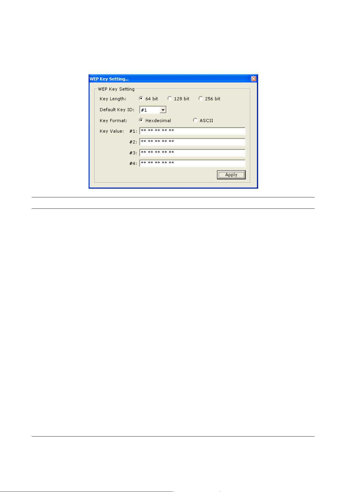
3.3.1 WEP Setting
Parameter Description
Key Length You may select the 64-b it, 128-bit or 25 6-bit to encrypt
transmitted data . Larger ke y length will provide hi gher level of
security, but the thr oughput will be lo wer.
Default Key ID Select one of the keys (1~4) as the encryption key.
Key Format Hexdecimal – Only “A-F“, “a-f“ and “0-9“ are allowed to be set as
WEP key.
ASCII –Num erical va lues, char acters or signs are allo wed to be
the WEP key. It is more recognizable for user.
Key1 ~ Ke y4 The keys are used to enc rypt data tr ansm itted in the wireles s
network. Fill the text box by following the rules below.
64-bit – Inpu t 10-digi t Hex va lues or 5- digit A SCII valu es as the
encryption ke ys. For ex ample: “ 0123456 aef“ or “ Guest“.
128-bit – Input 26-d igit Hex values or 13- digit ASCII va lues as the
encryption ke ys. For ex ample:
“01234567890 12345678 9abcdef“ or “adm inistrat or“.
256-bit – Input 58-d igit Hex values or 29- digit ASCII va lues as the
encryption ke ys.
Change/Appl y Click “Change“ will en able you t o setup the W EP key. In t he
meantime, the button will chan ge to “Ap ply“ for you to c onfirm
your settings .
15
Page 21
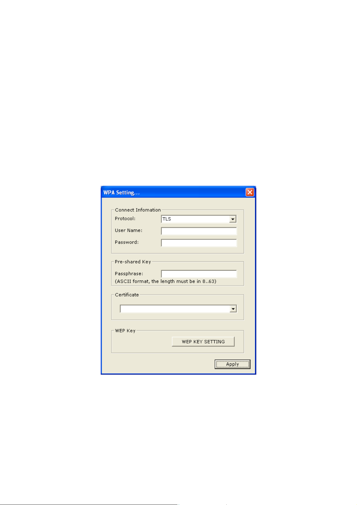
3.3.2 WPA Setting
The adapter c an autom aticall y detect the W PA setting of the AP which th e adapter chooses
to connect f rom the “ Availabl e Network “ list. T o connec t to the AP, you should setup the
same settings with the A P.
There are two kinds of W PA mode: W PA and WP A-PSK. W PA is des igned for enterpr ise
which requir es a RADI US Ser ver and C ertific ate Ser ver for t he auth enticati on. W PA-PSK is
a special m ode desig ned for home and small business users who do not have acc ess to
network authent ication servers . In this mode, t he user m anually e nters the s tarting
password in their ac cess point or rout er, as well as in each wire less station i n the network.
WPA takes ov er autom atically fr om that point, k eeping unauthori zed user s that do n't have
the matching pas sword f rom j oining the network , while enc rypting the data tr aveling
between authori zed devic es.
16
Page 22

Parameter Description
Connect Infor mation It is the set ting for W PA or W PA-PSK mode.
Protoco l This adapter supports two kind of protoc ol for aut henticat ion
including T LS and P EAP. T LS and P EAP requ ires a c ertific ate
which is provide d by the Certif icate Server. P EAP requires a set
of user name and password in addition. To get the certificate and
the personal us er nam e and pass word, pleas e contac t with your
administrator .
TLS – Select a certific ate fr om the “C ertifica te“ lis t.
PEAP – Input the “Us er Name“ an d “Pass word“ and also sel ect a
certificate f rom the “ Certif icate“ lis t.
User Nam e It is the set ting for PEAP protocol. The “Us er Name“ should be set
in RADIUS Server.
Password It is the setting for PEAP protocol. The “Password“ should be set
in RADIUS Server.
Pre-shared Ke y It is the setting for W PA-PSK m ode. Enter 8 to 63 digits of ASCII
format to be the password for the authentication within the
network.
Certificate All the available certificates for TLS or PEAP will display in the
list. Please select a proper certificate for the wireless
authenticati on.
Note that the certificate of wireless station should be imported to
the Browser s uch as In ternet Ex plorer. T o revie w if the c ertific ate
has been imported pr operly, pleas e follow the ste ps below.
1. Open “Internet Explorer“.
2. Select “Too ls“ from menu bar and the n select “ Interne t
Options“.
3. Click “Conten t“ tab and then cl ick “Cer tificates “.
WEP Key If the AP uses WEP da ta encr yption func tion, p lease Cl ick “W EP
KEY SETTING“ to s etup the W EP k ey.
W EP KEY SETT ING Setup the four s ets of WEP ke y by click ing the b utton.
Change/Appl y Click “Change“ will enab le you to setup the W PA setting. In the
meantime, the button will chan ge to “Ap ply“ for you to c onfirm
your settings .
17
Page 23
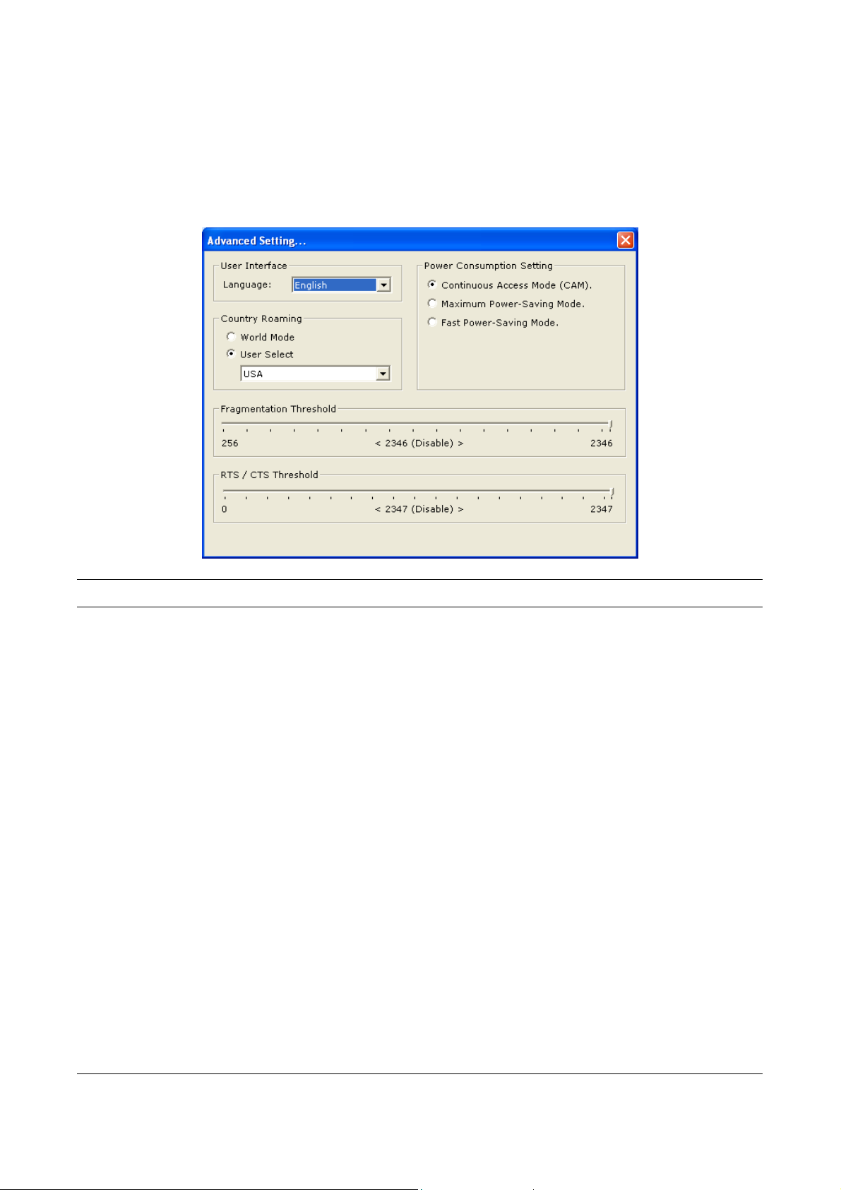
3.4 Advanced Setting
The “Advanced Setting” allows us er to enable/d isable c ountr y roaming, s etup po wer
consumption, f ragment ation thr eshold a nd RTS/C TS thresho ld of the adapt er.
Parameter Description
User Interfac e Select t he disp lay langu age of t he utilit y. Two la nguages are
enabled inc luding Eng lish a nd Tradi tional C hinese.
Country Roaming IEEE 802.11d (Country Roaming) is a standard that enable the
wireless devices work at the proper transm ission power an d radio
channel regul ated b y the countr y where the user is locat ed.
World Mode – Enable the c ountry r oaming f unction, t he adapter
will follow the setting of the c onnecting AP autom atica lly.
User Select – Disa ble the c ountry ro aming func tion, us ers can
select the co untry where they are located. The avai lable cha nnel
differs from countr y user selec ted.
Power Consumpti on Setting Continuous Access Mode (CAM) – The adapter will always set
in active m ode.
Maximum Power-Saving Mode – Enab le the adapter in the
power saving m ode when it is idle .
Fast Power-Saving Mode – Enab le the adapter in the power
saving mode when it is idle, bu t some com ponents of the ad apter
is still ali ve. In th is mode, t he power c onsum ption is larger than
“Max“ mode.
18
Page 24
Parameter Description
Fragementatio n Thres hold The value defines the m aximum size of pac kets, an y pack et size
larger than th e value will be f ragmented. If you h ave decre ased
this value and ex perience hi gh packet error r ates, you can
increase it again, bu t it will likel y decrease overal l network
performance. Select a s etting within a r ange of 2 56 to 234 6 bytes.
Minor change is recommended.
RTS / CTS Thr eshold Minimum pack et size r equired f or an RT S/CTS (R equest T o
Send/Clear t o Send) . For pack ets sm aller than t his thr eshold, an
RTS/CTS is not sent an d the pac ket is tra nsmitted d irectl y to the
WLAN. Select a sett ing within a ran ge of 0 to 2347 bytes. Minor
change is rec ommende d
3.5 Software AP Mode
This adapter can run as a wir eless A P. The re lative config urations of the AP inclu ding
channel, SSI D, MAC A ddress F iltering, W EP enc ryption and so on are de scribed as follo ws.
3.5.1 AP Connection Status
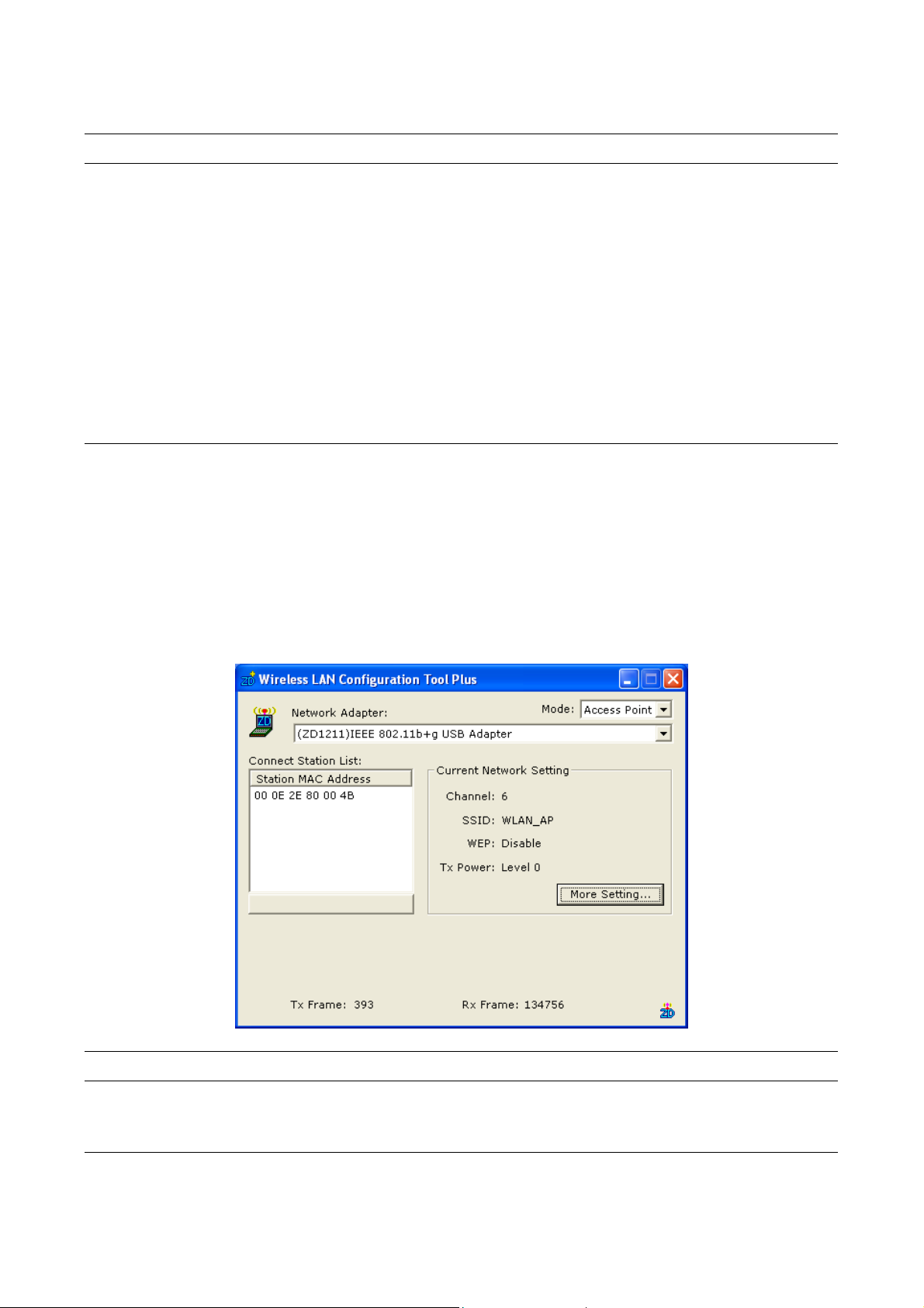
Parameter Description
Mode Station – Set the USB adapter a wireless station.
Access Point – Turns the U SB adapt er to func tion as a wireless
AP.
19
Page 25
Parameter Description
Network Adapter Display the product inform ation of the USB Adapt er.
Connect Station List Display all the MAC Addresses of the wireless stations connecting
to the AP.
Current Network Setting Display the c onnection s etting of the curr ent netw ork. It inc ludes
Channel, SSID, W EP and T X Power Level.
More Setting For setting m ore funct ions includ ing dis able/enabl e W EP, MAC
Address Filter and Br idge Adapter, etc. Pl ease ref er to Sect ion
3.5.2.
TX Frame It shows the num ber of data fram es whic h are tra nsmitted b y the
AP successfully.
RX Frame It shows the num ber of data fram es whic h are recei ved b y the AP
successfully.
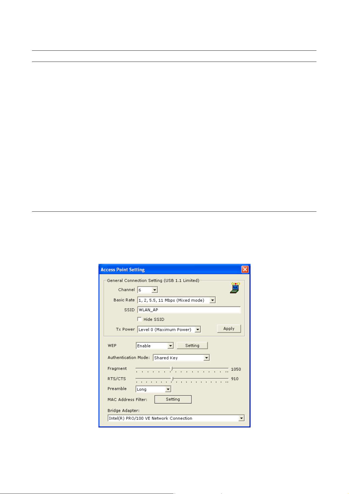
3.5.2 AP General Connection Setting
Click “More S etting”, us ers are a llowed to setup t he AP con nection s etting, E ncryption
Setting and other advanced functions.
20
Page 26

Parameter Description
General Con nection Setting
Channe l Select the n umber of the radio channe l used b y the AP. The
wireless stati ons which connect to the AP s hould s et up the s ame
channel.
Basic Rate Select the basic da ta transm ission spe ed suppor ts by the AP.
When the AP wor ks in 1 1b mode, t he max imum data r ate is
11Mbps so that there ar e two op tions incl uding “ 1, 2 Mbps ( Mixed
Mode)“ and “1, 2, 5.5, 11 Mbps (Mixed Mode) ” you can select .
SSID The SSID (up to 32 print able ASCII c haracters ) is the u nique
name identifie d in a WLAN. The ID pre vents the uninte ntional
merging of t wo co-loc ated W LANs.
The default S SID of t he AP is “W LAN_AP“. Wir eless stati ons
connect to the AP shoul d set up th e same SSI D as the AP.
Hide SS ID If “Hide SSID“ check box is enab led, the AP will n ot appear in the
site survey list of an y wireless s tations. I t means only the wireless
stations set t he same S SID can c onnect to the AP . It avoids the
AP being connected by unauthorized users.
Tx Po wer There are f our leve ls for you to set up the trans mission p ower of
the AP. The higher trans mission power , the larger trans mission
distance and wire less cover age.
Change/Ap ply Cl i c k “Cha n g e “ wi l l e n a b l e y o u t o set u p t h e p a r a met e rs o f
“General Connec tion Set ting“. In the mea ntime, t he button will
change to “Ap ply“ for you to co nfirm your setting s.
WEP Enable or d isable W EP encr yption func tion. If the W EP functio n is
enabled, onl y wireles s statio ns with t he sam e defau lt key and
WEP key sett ing can c onnect to the AP.
Setting Click “Setting“ to set up the W EP k ey. Please r efer to Sectio n 3.3
for more description.
Authentication Mode Open System – No authentication is needed for connecting to the
AP.
Shared Key – Only wireless s tations us ing a s hared k ey (W EP Key
identified) ar e allo wed to con necting to the A P.
21
Page 27
Parameter Description
Fragement The value def ines the m aximum size of pac kets, an y packet s ize
larger than th e value will be f ragmented. If you h ave decre ased
this value and ex perience hi gh packet error r ates, you can
increase it again, bu t it will likel y decrease overal l network
performance. Select a s etting within a r ange of 2 56 to 234 6 bytes.
Minor change is recommended.
RTS / CTS Minimum pack et size r equired f or an RT S/CTS (R equest T o
Send/Clear t o Send) . For pack ets sm aller than t his thr eshold, an
RTS/CTS is not sent an d the pac ket is tra nsmitted d irectl y to the
WLAN. Select a sett ing within a ran ge of 0 to 2347 bytes. Minor
change is rec ommende d.
Preamble The preamble defines the lengt h of the C RC bloc k for
communicatio n among t he wire less net works . There are t wo
modes includ ing Long and Short. High net work traf fic areas
should use the shorter preamble type.
MAC Address Filter This AP can pro tect from the unaut horized user s by MAC Address
filtering. Pleas e refer to Sect ion 3.5.3.
Bridge Adapter Wireless stations connect to the AP can access to the wired
network through th e bridge adapter . You can select an Et hernet
adapter in the list be th e bridge betwe en the wireless and wired
networks.
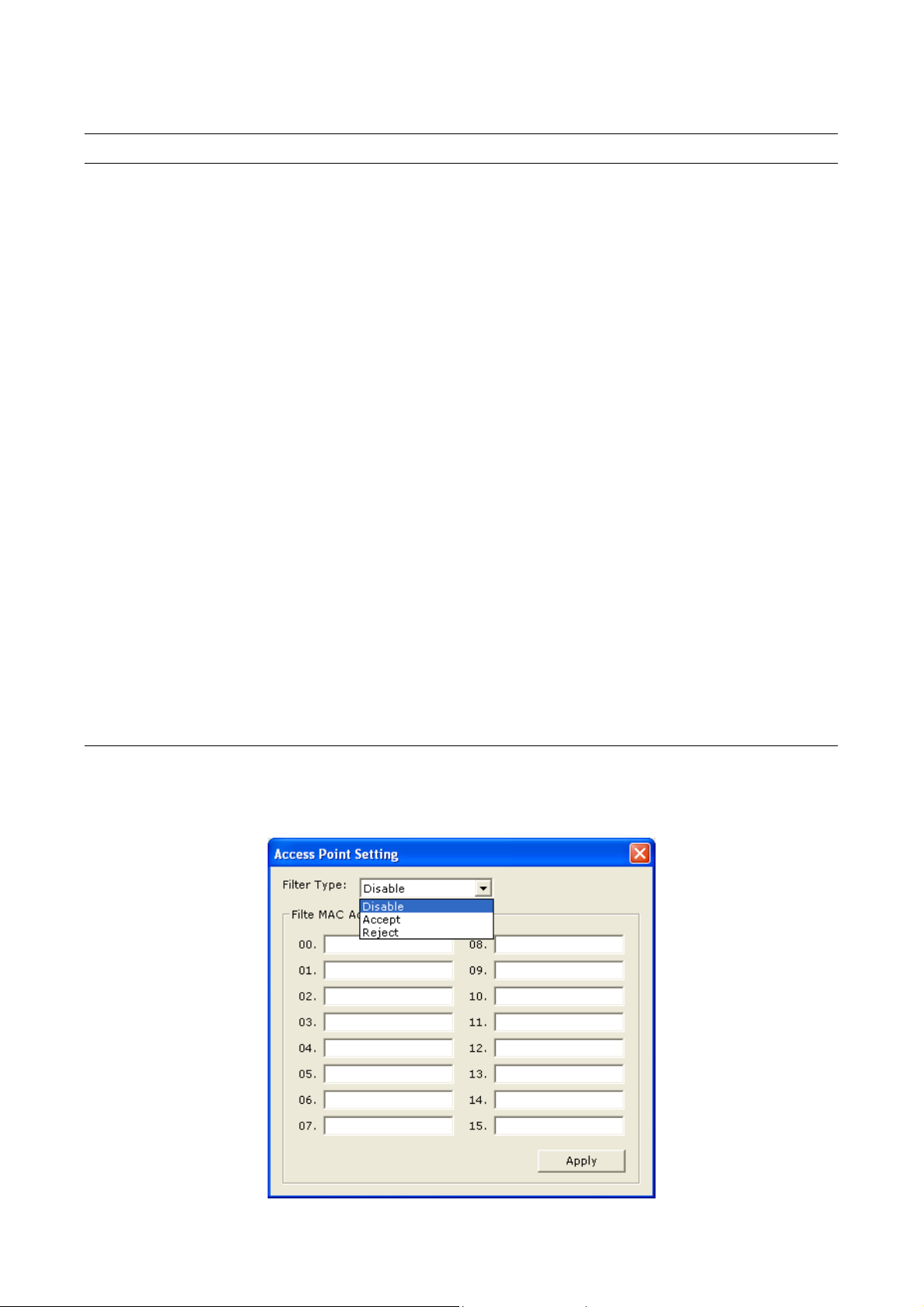
3.5.3 MAC Address Filter
22
Page 28

Parameter Description
Filter Type Disable – Disabl e the MAC Address f ilter func tion.
Accept – Only the wirele ss statio ns with t he MAC A ddresses
setup in the table can c onnect t o the AP .
Reject – The wireless stations with the MAC Addresses setup in
the table will be rejected to connec t to the AP .
Filter MAC Addr ess MAC Address is a unique identifica tion for hard ware devices in
the network . It is a 1 2-digit h exadec imal va lues.
There are fifte en sets of MAC Addresses can be setup in th e
table. Fill the MAC Addr esses of wireles s stations you want to
accept or reject to acces s the AP i n this t able.
Change/Apply Click “Change“ will act ivate t he setting of MAC Address F ilter. In
the meantim e, the butto n will ch ange to “ Apply“ fo r you to confirm
your settings .
23
Page 29

4 Troubleshooting
This chapter provides s oluti ons to pro blems usually e ncountere d durin g the ins tallat ion and
operation of the ad apter.
1. What is the I EEE 802. 11g stand ard?
802.11g is th e new IEEE standar d for hig h-speed wireless LA N comm unications that
provides for u p to 54 M bps dat a rate i n the 2.4 G Hz ban d. 802.11 g is quic kly becom ing
the next mainstream wireless LAN technology for the home, office and public networks.
802.11g defin es the use of the s ame OFD M modu lation tec hnique s pecifie d in IEE E
802.11a for t he 5 GH z freque ncy band a nd appl ies it in the sam e 2.4 GH z freque ncy
band as IEEE 8 02.11b. The 802. 11g stan dard requ ires back ward com patibilit y with
802.11b.
The standard s pecif ically c alls for:
A. A new physical layer for the 802.11 Medium Access Control (MAC) in the 2.4 GHz
frequency band, k nown as the extende d rate PHY (ER P). The ERP adds OFDM as
a mandatory ne w coding schem e for 6, 12 and 24 Mb ps (mand atory spe eds), and
18, 36, 48 and 54 Mbps (optio nal speeds ). The ERP inc ludes the m odulat ion
schemes found in 802.1 1b includ ing CCK f or 11 an d 5.5 Mbps and Bar ker cod e
modulation f or 2 and 1 Mbps.
B. A protect ion mec hanism c alled RTS /CTS tha t governs how 802 .11g devic es and
802.11b devices interoperate.
2. What is the I EEE 802. 11b stan dard?
The IEEE 802. 11b W ireless LAN s tandard s ubcom mittee, wh ich form ulates t he
standard for t he industr y. The objective is to e nable wire less LAN hardwa re from
different m anufactures to comm unicate.
3. What does IEE E 802.11 feature su pport?
The product su pports th e follo wing IEEE 802.11 functions:
CSMA/CA plus Ack nowledge Prot ocol
Multi-Cha nnel Roam ing
Automatic Rate S election
RTS/CTS Featur e
Fragmentation
Power Management
4. What is Ad-hoc?
An Ad-hoc integr ated wireless LAN is a group of com puters, each has a Wireless LAN
adapter, Connecte d as an independ ent wireless L AN. Ad hoc wireles s LAN is
applicable at a depar tmental sc ale for a branch o r SOHO operatio n.
24
Page 30

5. What is Infrast ructure?
An integrated wir eless and wireles s and wired LAN is c alled an Infrastr ucture
configuration . Infrastruct ure is applica ble to enterpr ise scale for wir eless acc ess to
central databas e, or wireless ap plication for mobile work ers.
6. What is BSS I D?
A specific Ad hoc L AN is called a Bas ic Service Se t (BSS). Com puters in a BSS m ust
be configured with the s ame BSS ID .
7. What is WEP?
WEP is Wired Equ ivalent Pri vacy, a data priv acy mechanis m based on a 40 bit shared
key algorithm , as descr ibed in th e IEEE 8 02 .11 st andard.
8. What is TKIP?
TKIP is a quick- fix method to quick ly overcom e the inherent weak nesses in WEP
security, espec iall y the reus e of enc ryptio n keys. TKIP is involved in the I EEE 802. 11i
WLAN securit y standar d, and th e specif ication m ight be officia lly releas ed by ear ly
2003.
9. What is AES?
AES (Advanced Encr yption Stan dard), a c hip-bas ed secur ity, has b een deve loped to
ensure the hig hest degr ee of sec urity a nd authen ticity f or digita l inform ation, wh erever
and however c ommunic ated or s tored, while mak ing more ef ficient us e of hard ware
and/or softwar e than pr evious e ncryptio n standar ds. It is a lso incl uded in IEEE 802.1 1i
standard. Compar e with AES, TKIP is a temporary prot ocol for replac ing W EP security
until manufact urers implem ent AES at the har dware level .
10. Can Wireless products support printer sharing?
Wireless pro ducts perf orm the s ame func tion as LAN produc ts. Ther efore, W ireless
products can work with Netware, W indows 2000, or other LA N operating s ystems to
support printer or file sharing.
11. Would the information be intercepted while transmitting on air?
WLAN features two-fol d protect ion in sec urity. O n the h ardware si de, as wit h Direct
Sequence Sprea d Spectrum technology, it has the inherent sec urity featu re of
scrambling. O n the sof tware s ide, W LAN series of fer the e ncryptio n functi on (W EP) to
enhance security and Access Control. Users can set it up depending upon their needs.
25
Page 31

12. What is DSSS?What is FHSS?And what are t heir diff erences?
Frequency-ho pping spr ead-spec trum (FHS S) uses a narrowb and carr ier that changes
frequency in a patter n that is known to bo th transmitter and receiver. Pro perly
synchronized, the net ef fect is to main tain a s ingle logical channel. T o an un intended
receiver, FHSS appears to be short-duration impulse noise. Direct-sequence spreadspectrum (DSS S) gener ates a re dundant b it patte rn for eac h bit to be transm itted. T his
bit pattern is called a chip (or chippi ng code). T he lo nger the c hip is, the grea ter the
probabilit y that the or iginal data can b e reco vered. E ven if o ne or m ore bits in the chi p
are damaged during tr ansmis sion, stat istica l techniqu es embed ded in t he radio c an
recover the origina l data without-th e need for retransm ission. To an uni ntended
receiver, DSSS appe ars as low power wideband noise an d is rejected ( ignored) by
most narrowband receivers.
13. What is Spread Spect rum?
Spread Spectrum technolog y is a wideband radi o frequency tech nique devel oped by
the military for use in reliable, secure, mission-critical communication systems. It is
designed to tr ade off bandwidth effici ency for r eliabilit y, integr ity, and s ecurit y. In oth er
words, more band width is consum ed than in the case of narrowband tran smission, but
the trade off produces a signa l that is, in eff ect, louder and thus easier t o detect ,
provided that the recei ver knows the par ameters of the spr ead-spec trum sig nal being
broadcast. If a receiver is not t uned to t he right frequenc y, a spre ad –spec trum sign al
looks like b ackgroun d noise. There ar e two m ain alter natives, Direct Sequence Spread
Spectrum (DSSS) and Frequenc y Hopping Sprea d Spectrum (FHS S).
26
 Loading...