

Page 1

Broadband Router User Guide
Page 2

Broadband Router User Guide
March, 2001
Limitation of Liability
Information in this document is subject to change without notice. The material contained herein is supplied without
representation or warranty of any kind. Therefore assumes no responsibility and shall have no liability of any kind
arising from the supply or use of this document or the material contained herein.
Page 3

1
About This User Guide
Welcome to the Networking world of multifunction routers! Thank you for investing
in a Broadband Router. We are dedicated to provide the most efficient, easy to
configure, and trouble free equipment in the networking industry.
This manual is intended as a basic introduction to your Broadband Router. It supplies
enough information to make the Broadband Router operational in most common
environments: connecting to the Internet , receiving calls from dial-in users, or
connecting to another network through the telephone network.
We’ll describe how to use your web browser to configure the Broadband Router and
to perform some basic operations, e.g. upgrading the software, or viewing the
connection log, a task which may be useful in ongoing operations. Finally, we’ll tell
you how to obtain information and help for subjects that are beyond the scope of this
manual.
This manual consists of seven chapters and three appendixes:
Chapter One: Introduction, explains the features and capabilities of the Broadband
Router.
Chapter Two: Installing the Broadband Router, gives the simple steps you follow to
install the Broadband Router and configure your workstations.
Chapter Three: Configuring the Broadband Router, explains how to log in to the
ARM Manager, describes the browser screen, and provides the steps needed to
configure your Broadband Router for specific applications. It provides easy-to-follow
instructions for quick Internet access and provides a guide to the most popular
Broadband Router configurations.
Chapter Four: Advanced Configuration, provides information on advanced router
configuration setup.
Chapter Five: Managing the Broadband Router, explains the management features
of the Broadband Router.
Chapter Six: Messages, lists messages you may see in the ARM message window,
and what they mean.
Appendix A: Specifications
Appendix B: Glossary
Appendix C: Warranty, Copyright, FCC Notice
Safety Warnings
• The Broadband Router is not intended to be serviced by the user. Do not open
the case.
• This product is intended to be supplied by a Listed Direct Plug-In Power Unit
marked "Class 2" and rated 9 V ac, 1 A.
Page 4

iii
Contents
Chapter 1 Introduction?
Overview of the Broadband Router Multifunction Router
Broadband Router Applications
Accessing the Internet
Accessing Servers from the Public Network
Creating a Virtual Private Network (VPN)
A Configuration Example
A Security Overview
A Physical Look at the Broadband Router
The Connectors on the Back
The LEDs on the Front
Chapter 2 Installing the Broadband Router
Installing the Broadband Router
Setting Up a Windows PC for Configuring the Broadband Router
Connecting more Devices through a Hub to the Broadband Router
Chapter 3 Configuring the Broadband Router
Internet Access in Five Minutes
Using Different Browsers for Broadband Router Configuration
Logging On
Customizing the ARM for Your Specific Needs
Overview of The ARM Browser Screen
What is a Connection Profile?
Selecting Internet Access Interface
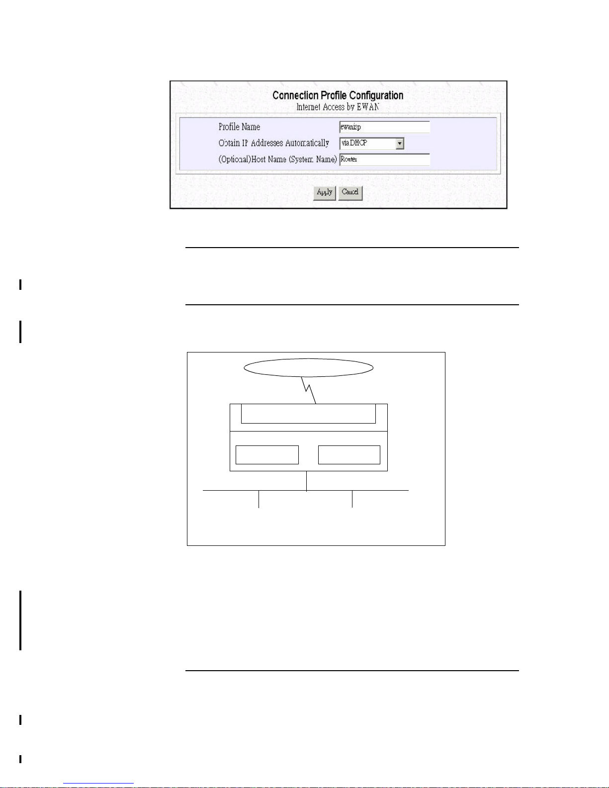
Configuring a Basic Internet Access Profile via EWAN
Setting Up Internet Access with Advanced Features
Modifying Public and Private IP Addresses
Setting the System Time
Setting Internet Access Time Restrictions
Chapter 4 Advanced Configuration
Configuring and Using Port Address Translation
Configuring Port Address Translation
Static DHCP Assignments
Creating VPN Connection Profiles
To Configure VPN Remote Office Access Profiles
Set up a VPN Connection Profile
Advanced Options Setup
Packet Filtering
A Packet Filtering Overview
Configuring IP Packet Rules
Configuring IPX Packet Rules
To Configure Advanced IP Settings
Page 5

iv
To Configure Advanced IP Settings
The IP Routing Table
To Configure IPX Settings
The IPX Routing Table
The IPX SAP Table
To Enable Bridging Learning
Chapter 5 Managing the Broadband Router
How to View the Connection Log
How to Upgrade the Broadband Router Features/Software
How to Save or Clear Configuration Changes
How to Reset the Broadband Router
How to Change the ARM Password
What if I Forget the Password?
How to Customize the ARM Interface
How to Configure General System Settings
Chapter 6 Messages
Messages
Appendix A Broadband Router Specifications
Appendix B Glossary
Appendix C Warranty, Copyrights, FCC Notice
Warranty
Copyrights
FCC Part 15 Notice
Page 6

1-1
1Broadband Router
1 Introduction
This chapter gives the introduction to the Broadband Router.
What’s in the Box?
Your Broadband Router box should contain the items listed below
• 1 Broadband Router
• 1 AC Adapter, AC 9V 1A
• 1 female to female 9 pin cable to connect PC COM port and Broadband Router
Console port.
• 1 UTP CAT5 crossover LAN cable to connect EWAN port and ADSL / Cable
Modem
Note: Some Cable Modems use straight through cable
• 1 CD-ROM containing the online documentation
• 1 Quick Start Guide
• 1 Warranty and registration card
Overview of the Broadband Router
The Broadband Router is a small desktop router that sits between your local Ethernet
network and a remote network (e.g., the Internet or a remote office). The Broadband
Router contains an EWAN port connecting to Internet via external ADSL/Cable
modem , a COM port worked as a managemant Console , and a one-port 10/100
Ethernet switch. Data comes into the Broadband Router from the local LAN and then
is “routed” to the remote network. In addition to its capability to route IP/IPX traffic,
the Broadband Router also acts as a bridge for other network protocols, such as
Appletalk or SNA.
Broadband Router Applications
The main functions of the Broadband Router
-to allow devices on your LAN to access the Internet,
-to access servers from the public network,
-to create Virtual Private Network (VPN).
Accessing the Internet
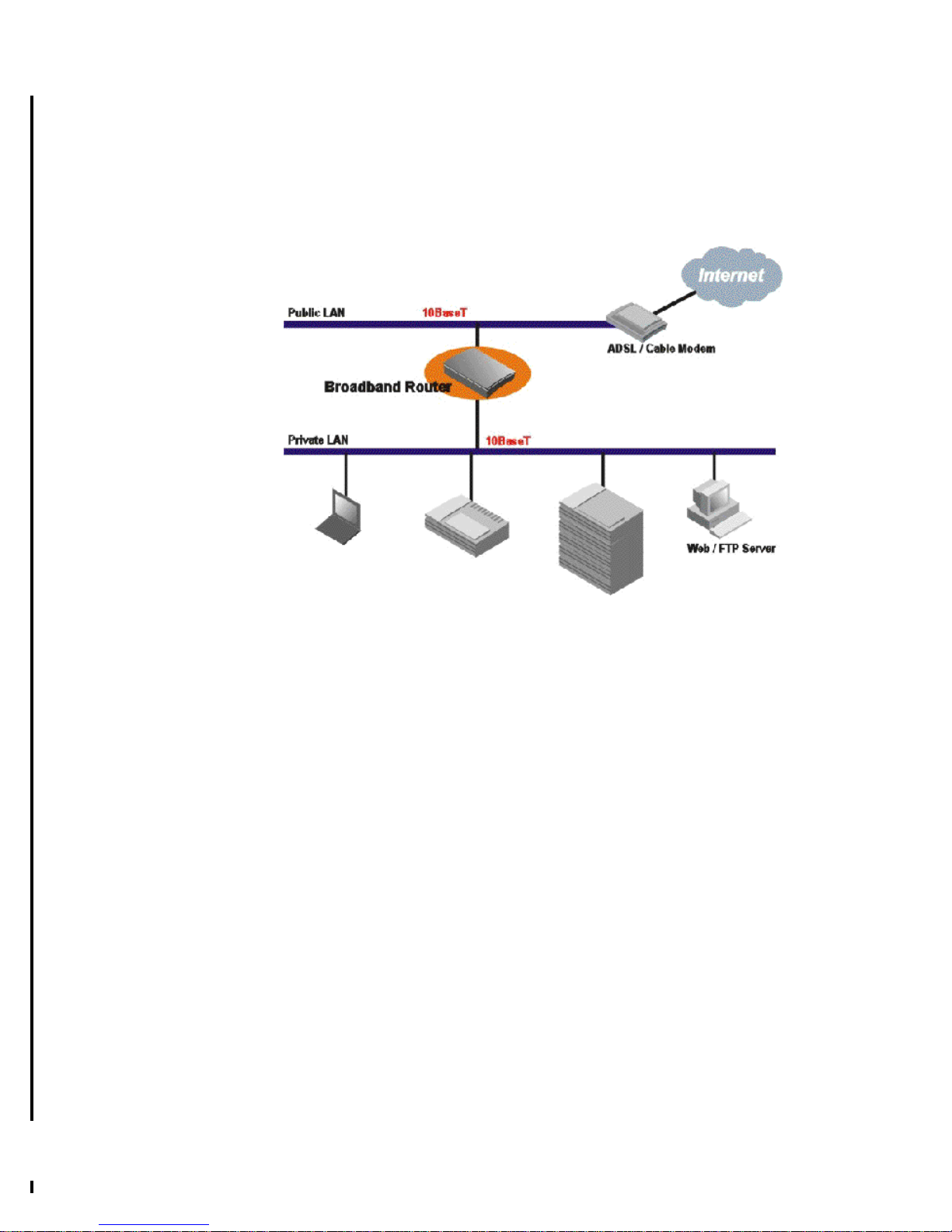
The most common use for the Broadband Router is to provide Internet access, so that
everyone on your LAN can surf the web and send/receive email or files.
Page 7
1-2
The Broadband Router automatically acquires the necessary IP address when the
connection to the Internet is established. You don’t need to apply for and assign an IP
address to each PC or workstation on your network.
ivate wide area network with Broadband Router via external ISDN TA/modem and
provide Internet access for everyone on your LAN to surf the web and send/receive email or files simultaneously
Figure 1-1 Internet Access
Accessing Servers from the Public Network
If you want special servers to be accessible by remote users across the Internet (e.g.,
an e-mail server, an FTP server, or a web server), you can configure the Broadband
Router to proxy the service from its own address. This means that the remote user can
address the router as if it were the special server and the Broadband Router will redirect this connection to the appropriate computer on the network.
Creating a Virtual Private Network (VPN)
Virtual Private Networking (VPN) provides a means to connect remote LANs over
the Internet, while only local toll charges to an Internet Service Provider are incurred
even if the two LANs are physically remote to each other.
To create a VPN between two sites, a special connection called “tunnel” followed by
a VPN data session has to be set up over the Internet. After a VPN data session is set
up, data can be sent over it, optionally encrypted to prevent unauthorized access.
Additionally, VPN tunnels allow IP, IPX and Bridging traffic to flow across the
Internet, including NetBIOS information (for Windows networking) encapsulated
within IP or IPX packets.
All information required for a VPN is defined in a VPN profile, which contains, for
example, the IP address of the VPN partner and authentication information (including
the encryption key that is used).
When a PC from one site tries to communicate with a device on the other site for the
Page 8

1-3
first time, the VPN tunnel and data session establishment process will be triggered
automatically. For the originating side, first the destination IP address will be used to
search for the corresponding VPN profile. Based on the information conifgured in the
matched VPN profile, a VPN tunnel is created, a VPN data session will be created
and authentication information exchanged, then data traffic can start to flow. For the
destination side, when a VPN data session creation is requested, the router will base
on the originating IP address to search for a matched profile. Once found, the
Broadband Router will use the information in the matched profile to authenticate the
incoming "call", after which data transfer can begin.
More than one VPN data sessions can be established over the same tunnel.
See chapter 4 for detailed configuration instructions.
Figure 1-2 Creating a Virtual Private Network
A Configuration Example
In Figure 1-3, two Broadband Routers are installed in two different locations. They
are connected to the Internet via ADSL/Cable modem, allowing users to surf the
Web. They are also connected to each other through the telephone network, forming a
private company network.
Figure 1-3 Connecting Two Private Networks
This example also illustrates an important feature of the Broadband Router that a
private device can be accessed from the Internet by mapping the application port
number to a port number on the Broadband Router. In this case, an Internet user
references the URL http://206.112.113.6, which was assigned to the Broadband
Page 9

1-4
Router by the ISP, and the Broadband Router will translate that address to
192.168.168.112, port 80.
All devices on both LANs (except for the Web servers) are configured to obtain their
IP addresses automatically (i.e., from the built-in DHCP server in the Broadband
Router). Since the Web Server on LAN #1 must have the same address all the time,
this machine has a statically configured DHCP address. These IP addresses are only
used in the local LAN environment, these devices naturally form a private network
(with default IP network address of 192.168.168.0) and are not accessible by users
across the Internet (if they are not mapped). In Broadband Router, it is possible to
assign public IP addresses obtained from your ISP and they will be accessible by
users across the Internet. These public addresses can co-exist in the same LAN
private address segment.
In order to let the LAN to LAN communications work, the default private network
address (192.168.168.0) for one of the above Broadband Router has to be changed
(to 192.168.170.0 in the above example). The traffic between these two networks is
secure because data are sent across the telephone network via a direct phone call.
A Security Overview
More and more people are concerned about security of their data in the Internet
The Broadband Router provides many ways to help make your network and your
data secure:
• All dial-in users and LAN-to-LAN communications require PPP PAP/CHAP/
MS-CHAP authentication (basically user name and password)
• The Broadband Router also supports call-back for dial-in users - so that remote
user are really who they say they are
• The Broadband Router uses a private IP addressing scheme to prevent devices on
your LAN from access by outside users
• Console, Telnet and ARM support password protection
• DES encryption with PPP/ECP negotiation is supported for VPN connections
• IP packet filtering may be used to futher enhance security requirements
A Physical Look at the Broadband Router
The Connectors on the Back
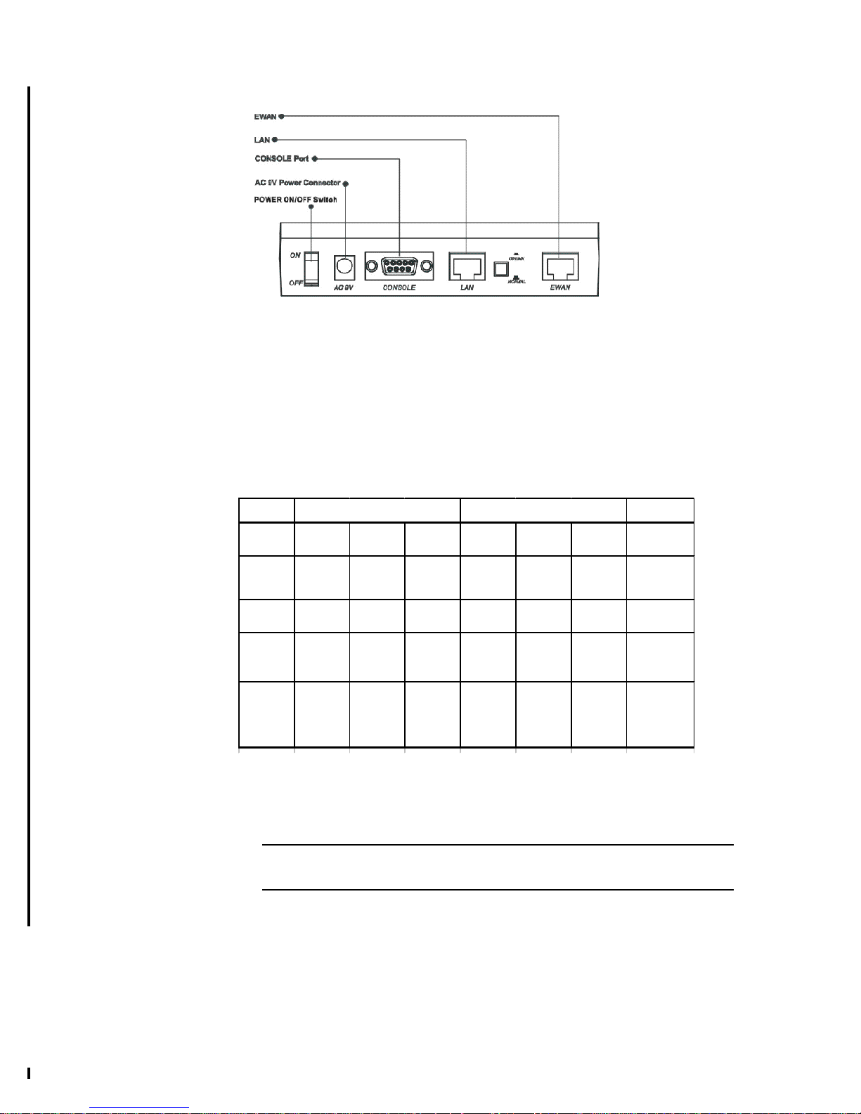
The following illustration shows the rear panel of Broadband Router.
(1 )1 RJ-45 10/100 Switch connectors for connecting to PCs and workstations or
connecting external Ethernet hub, or switch with uplink switch on port 1.
(2) 1 RJ-45 EWAN connector for connecting to Internet via ADSL/Cable modem
(3) 1 RS-232 DB-9 connector to be a Console port connecting to PC.
(4) 1 AC power connector for connecting through an AC power adapter (included as
part of the product) to the wall power outlet
(5) 1 power ON/OFF switch
Page 10
1-5
Figure 1-4 Broadband Router Connectors
The LEDs on the Front
There are 7 LEDs on the front of the Broadband Router that show connection and
traffic status of Power, PPPoE, EWAN and LAN ports:
Figure 1-5 LEDs
Note: Some of the features above are optional. Please refer to Appendix A for
the details.
POWER
LED1 LED2 LED3 LED4 LED5 LED6 LED7
PPPoE COL ACT COL ACT 10/100 Power
ON
PPPoE
Linkage N/A N/A N/A N/A 100Mbps Power On
OFF
No
PPPoE
Linkage N/A N/A N/A N/A 10 Mbps Power Off
FLASH
Sending
or
Receiving
Packet Collision
Sending
or
Receiving
Packet Collision
Sending
or
Receiving
Packet N/A N/A
LAN
EWAN
Page 11
2-1
2Broadband Router
2 Installing the Broadband Router
Now you should be ready to connect your Broadband Router devices on your LAN .
Follow these steps to install the Broadband Router:
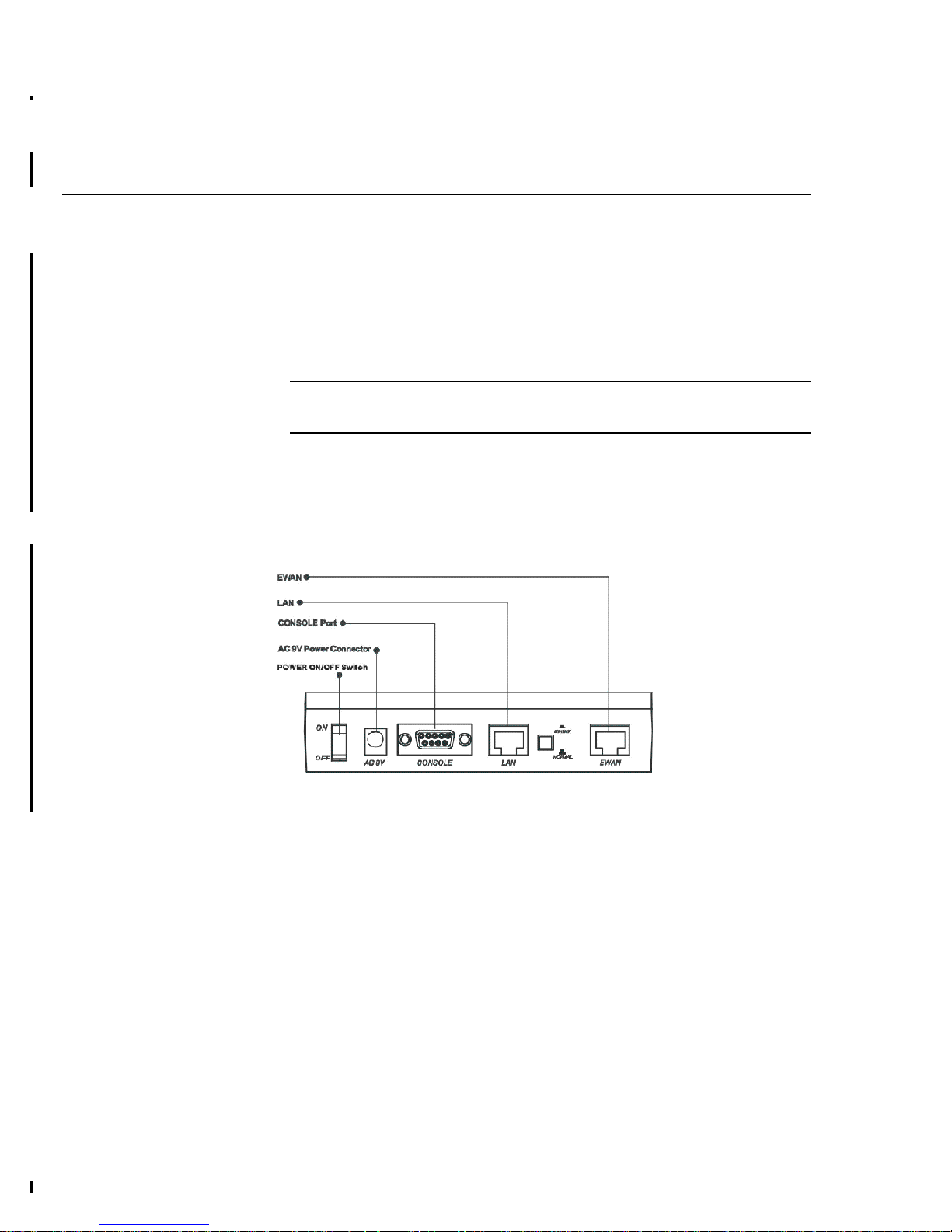
Step 1 Connect ADSL/Cable modem to the Broadband Router EWAN port using
crossover UTP CAT-5 LAN Cable.
Note: Some Cable Modems use straight through cable
Step 2 Connect PCs/Workstations to the LAN port of the Broadband Router. If
you are connecting a hub or switch, see “Connecting more Devices
through a Hub or switch to the Broadband Router “ later in this
chapter.
Step 3 Connect the AC adapter t the Broadband Routerand an electrical outlet.
Figure 2-1 Broadband Router Connectors
Page 12
2-2
Setting Up a Windows PC for Configuring the
Broadband Router
This section describes how to configure a PC on the LAN in order to communicate with
the Broadband Router
These PCs need to have an Ethernet interface cards installed, and be connected to the
Broadband Router either directly( to its LAN ports) or indirectly through an external
hub or switch. It shoud also have TCP/IP installed, enabled, and configured to obtain an
IP address automatically( i.e., through a DHCP server).
If TCP/IP is not already installed, follow the steps below for its installation.
Note: Any TCP/IP capable workstation can communicate with the Broadband
Router. To configure workstations other than Windows 95/98/NT, please consult the
manufacturer’s documentation.
Step 1 Connect your PC to one of the Broadband Router Switch ports. If you
connect to LAN port , you should use a straight LAN cable and set the
Uplink switch to the Normal position. or use a crossover LAN cable and set
the Uplink switch to Uplink. See Figure 2-3..
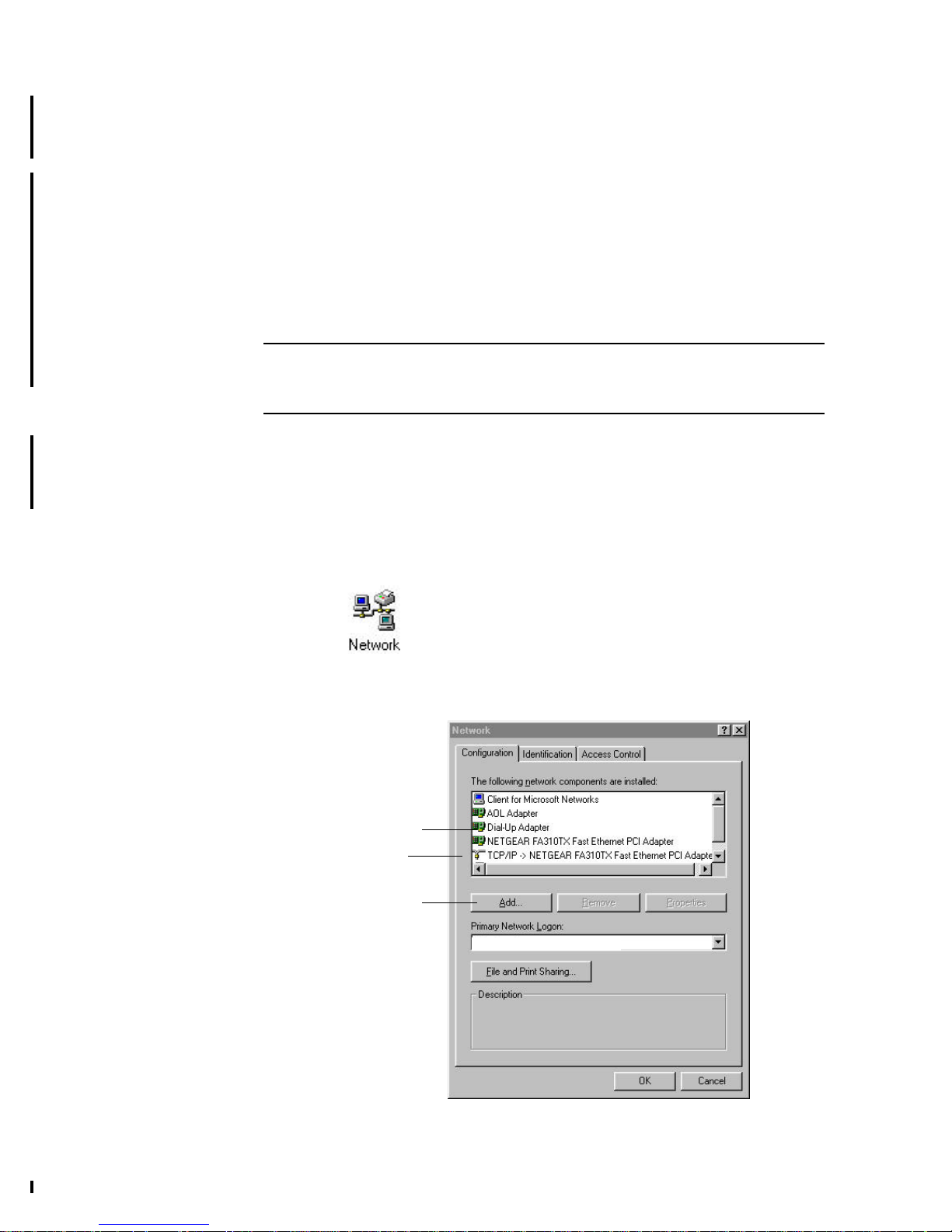
Step 2 From the Win95/98 Start Button, select Settings, then Control Panel. The
Win95/98 Control Panel displays.
Step 3 Double-click on the Network icon.
Step 4 Check your list of Network Components in the Network window
Configuration tab. If TCP/IP has already been installed, go to Step 8.
Otherwise, select Add to install it now.
Add button
Look for TCP/IP
Client for Microsoft Networks
Page 13
2-3
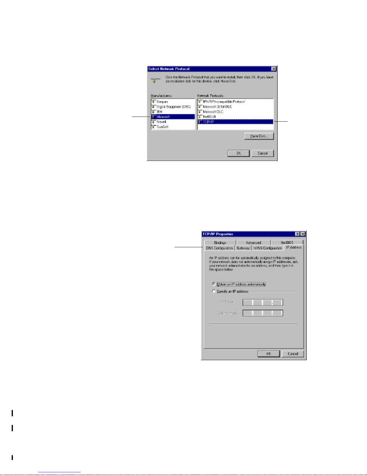
Step 5 In the new Network Component Type window, select Protocol.
Step 6 In the new Select Network Protocol window, select Microsoft in the
Manufacturers area.
Step 7 In the Network Protocols area of the same window, select TCP/IP, then
click OK. You may need your Win95/98 CD to complete the installation.
After TCP/IP installation is complete, go back to the Network window
shown in Step 4.
Step 8 Select TCP/IP in the list of Network Components.
Step 9 Click Properties, and check the settings in each of the TCP/IP Properties
window:
-Bindings Tab: both Client for Microsoft Networks and File and printer
sharing for Microsoft Networks should be selected.
-Gateway Tab: All fields should be blank
-DNS Configuration Tab: Disable DNS should be selected
-IP Address Tab: Obtain IP address automatically should be selected
Step 10 When the Broadband Router connected to the LAN (and powered on),
reboot the PC. After the PC is re-booted, you should be ready to configure
the Broadband Router. See Chapter 3.
Select
Microsoft
Select
TCP/IP
TCP/IP Properties Tabs
(IP Address Tab shown)
Page 14
2-4
Connecting more Devices through a Hub to the
Broadband Router
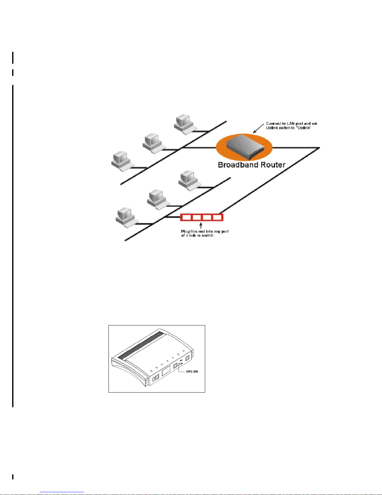
The Broadband Router provides four switch ports to allow up to four PCs or
Workstations to be connected to it directly. If you want to connect more devices, you
can connect an external hub or switch to LAN port , provided LAN port has been
configured as an Uplink port.
Figure 2-2 Connecting a Hub or Switch to the Broadband Router
The uplink switch is used to set LAN port as an uplink port. To set the uplink switch:
Step 1 Plug one end of a normal UTP CAT-5 cable into Port of the Broadband
Router , and the other end of the UTP CAT-5 cable into any normal
Ethernet hub, or switch.
Step 2 Set the switch to the Uplink position. See Figure 2-3
Figure 2-3 Uplink Switch
Page 15

3-1
3Broadband Router
3 Configuring the Broadband Router
Once you have completed the installation stage and have configured a PC properly as
described in chapter two, you are ready to configure the Broadband Router for actual
applications.
This chapter describes how to configure your Broadband Router for basic Internet
access, as well as for the following configurations:
• To set up Internet access with advanced features
• To set the system time
• To configure Internet access time restrictions
Internet Access in Five Minutes
In this section you will be shown how to configure the Broadband Router for basic
Internet access in less than five minutes using the web browser-based Acess Router
Manager (ARM).
Using Different Browsers for Broadband Router
Configuration
To configure your Broadband Router, you can use popular browsers such as
Netscape 4.5 and Internet Explorer 5.x. The following describes, after each browser is
brought up, how to use it to start the ARM interface:
Netscape Navigator 4.5 (or newer):
In the Location box (where you normally enter the URL address), enter the default
private IP address of the Broadband Router followed by hitting the return key:
http://192.168.168.230
Internet Explorer 5.0 (or newer):
In the Address box (where you normally enter the URL address), enter the default
private IP address of the Broadband Router followed by hitting the return key:
http://192.168.168.230
Logging On
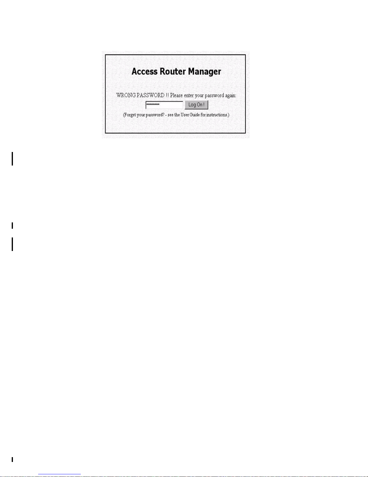
After entering the default IP address as described above, a password prompt screen
Page 16
3-2
will ask you to log on. If you are logging on for the first time, you should accept the
factory default password (which is “password”). The password is always displayed as
a string of asterisks (“*”). Clicking the Log On button will begin a Access Router
Manager (ARM) session. The next time you log in, even if you have modified the
password , the default password (“password”) will still be used as the default. You
need to change it to the correct password before you will be let in.
No matter what password you use, each character will always be displayed in the
logon prompt as a “*”.
If you forget the password, you need to follow steps described in chapter 5 to be able
to log on.
The Broadband Router comes with a basic feature set installed. If you have purchased
additional features from your distributor, you will also be given a “feature key”. In
this case, you will need to click the box below the Log On button that says “Check
here to install additional features” before you click the Log On button.
Page 17
3-3
Customizing the ARM for Your Specific Needs
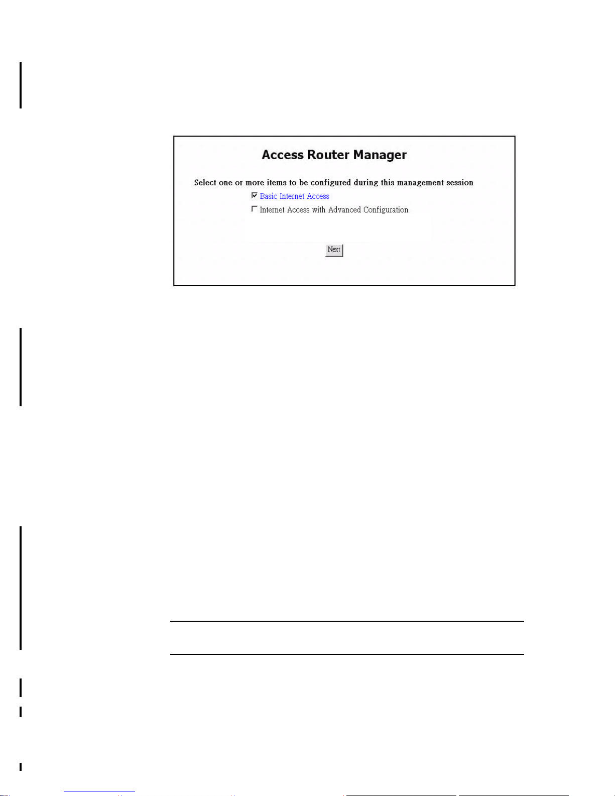
When you log on for the first time, the ARM Customization screen will be
automatically displayed, allowing you to customize the ARM session to suit your
own specific needs:
The choices available depend on what feature keys have been installed. The
selections you make determine what configuration menu and buttons will appear in
the ARM interface. For example, if you select Basic Internet Access only, the ARM
interface will display only buttons and screens that you need for basic Internet access.
If you subsequently use ARM to configure the Broadband Router for other
applications, you can return to this ARM Customization screen to “re-customize”
your ARM interface by selecting Customize User Interface from the ARM Menu
(on the left hand side of the ARM interface).
Basic Internet Access
Select this option if you need basic Internet access. This will enable you to configure
Internet Access for all of your LAN users.
Internet Access with Advanced Configuration
Select this option if you want to configure advanced options, such as changing the
private IP address (e.g., when you intend to create your own private WAN among
multiple Broadband Router ), or adding a public IP address (e.g., when you want to
install servers on the LAN which are accessible from the Internet).
Share Netware (IPX) Resource(optional)
Select this option if you use Novell servers on your network and want to allow dial-in
users or remote offices to share them.
Note: The choice displayed in this screen depend on the feature keys which are
installed in your system.
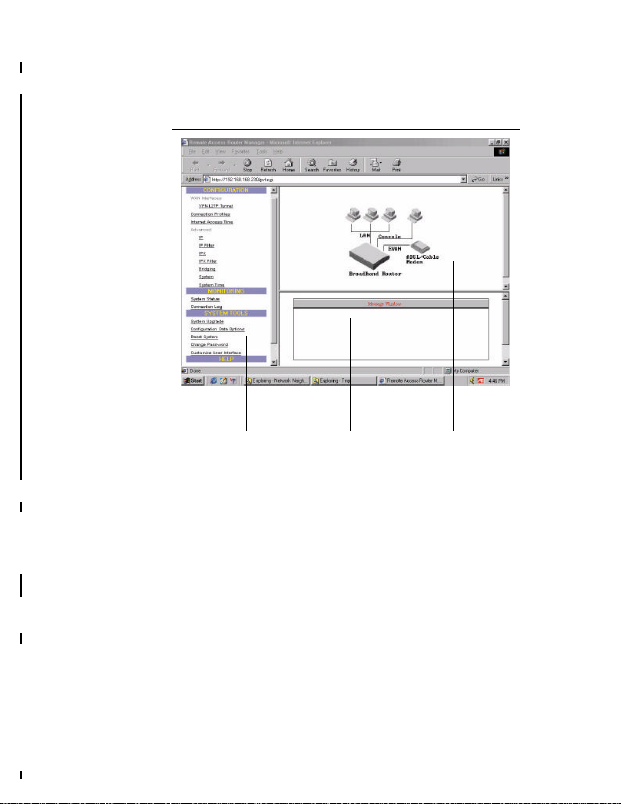
Overview of The ARM Browser Screen
Before you begin the configuration, take a moment to look at the ARM screen. Look
for these areas:
Page 18
3-4
• ARM Menu
• Configuration Window
• Message Window
• Status Window
ARM Menu
This part of the browser screen contains items you can click to display the various
screens for configuring your Broadband Router, including EWAN, connection
profiles, and protocols, as well as system monitoring, tools, and help.
Configuration Window
This is the window where the actual configuration screens appear. Before any
selection of the configuration is made, the window shows a picture of the Broadband
Router with cables and peripheral devices that can be connected to it.
Message Window
Whenever appropriate, the Broadband Router will display system status or error
messages in this window. For example, when you try to connect to the Internet, if you
had configured your password incorrectly, the message window will display an
appropriate message.
System Status Monitoring Window
This section displays statistics and the status of all interfaces.This window is invoked
AAARM Menu
AAMessage Window AAConfiguration Window
Page 19

3-5
as a separate browser screen from the main ARM browser screen and appears
automatically each time you start ARM. If you close this window, you can always
restart it or bringing it to the foreground by clicking Monitoring - System Status from
the ARM Menu. It does not contain any toolbars or browser menu buttons. Although
the main ARM screen will timeout, this screen will not, and will continue to be
operational as long as it is active.
The following statistics are reported for each interface:
Device: lists all interfaces, including both the physical interface (i.e., the LAN port,
the EWAN port).
Status: indicates the current state of the interface:
(I) For LAN: this will always show Up.
(II) For EWAN:
(i) PPPoE:
profile name: Sow the profile you used if the interface is up and
funtioning.
No call: Means that this interface is not connected and the profile of
EWAN port is idle.
Down: Means that this interface is not connected and no EWAN profile
added.
(ii) DHCP & No:
profile name: Show the profile you used if the interface is up and
funtioning.
Down: Means that this interface is not connected.
Xmt Pkts: indicates the number of packets that have been transmitted through the
interface.
Rcv Pkts: indicates the number of packets that the interface has received.
Err Pkts: indicates the number of error (bad) packets that have been received.
Disconnect: if an active interface has been selected (highlighted), clicking this button
will cause the connection to be taken down. The LAN interface is not affected by this
operation.
Clear: resets the selected statistics values to zero.
Device Rcv Pkts Err PktsXmt Pkts
LAN
EWAN
Up
Status
Down
192 191 0
0 0 0
Disconnect Clear
Page 20
3-6
What is a Connection Profile?
To access the Internet, you need to apply for an account with an ISP (Internet Service
Provider), who will provide you the ISP Account name and ISP Account Password
that you need to call, as well as phone number if necessary to dial-up to your ISP.
You need to enter such information into a “connection profile” in the Broadband
Router. Likewise, a connection profile needs to be created for each dial-in user, each
remote office, or each VPN user.
Essentially, a connection profile contains all information that the Broadband Router
needs to access the Internet, or support a remote dial-in user, or set up a connection
with a remote office, or create a VPN. Such information includes dial-up phone
numbers, authentication information (the local user name and password and possibly
the remote site user name password), plus other information that may be required for
the communication.
Selecting Internet Access Interface
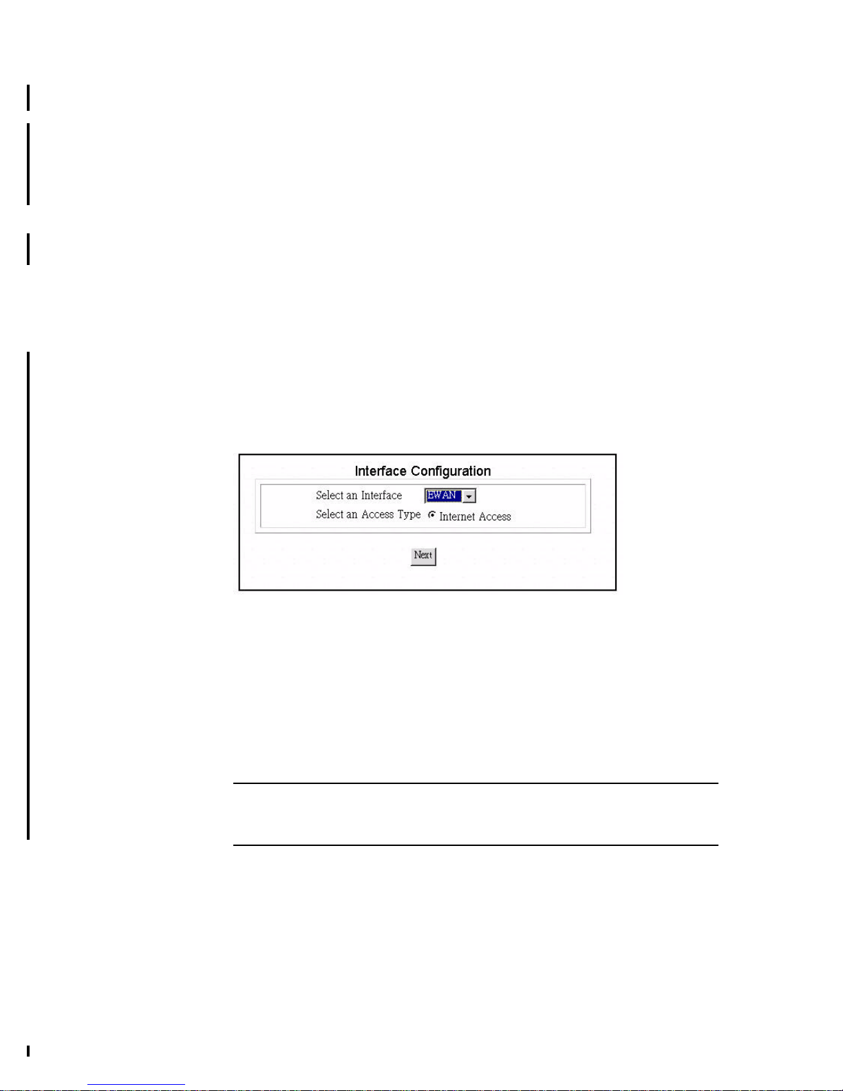
Select EWAN port to connect ADSL/Cable Modem.
The following screen show you the interface configuration ,please select EWAN to
be your interface from the Broadband Router.
Configuring a Basic Internet Access Profile (via
EWAN)
To configure an Internet access connection profile, from the ARM menu, press
Connection Profiles. If there are no other profiles at this point, you will immediately
enter a profile configuration screen. First decide what interface to use for Internet
access.
Step 1
Note: The ARM Customization screen is displayed the very first time you invoke
the ARM tool. To return to this screen, select Customize User Interface from the
ARM Menu.
Page 21
3-7
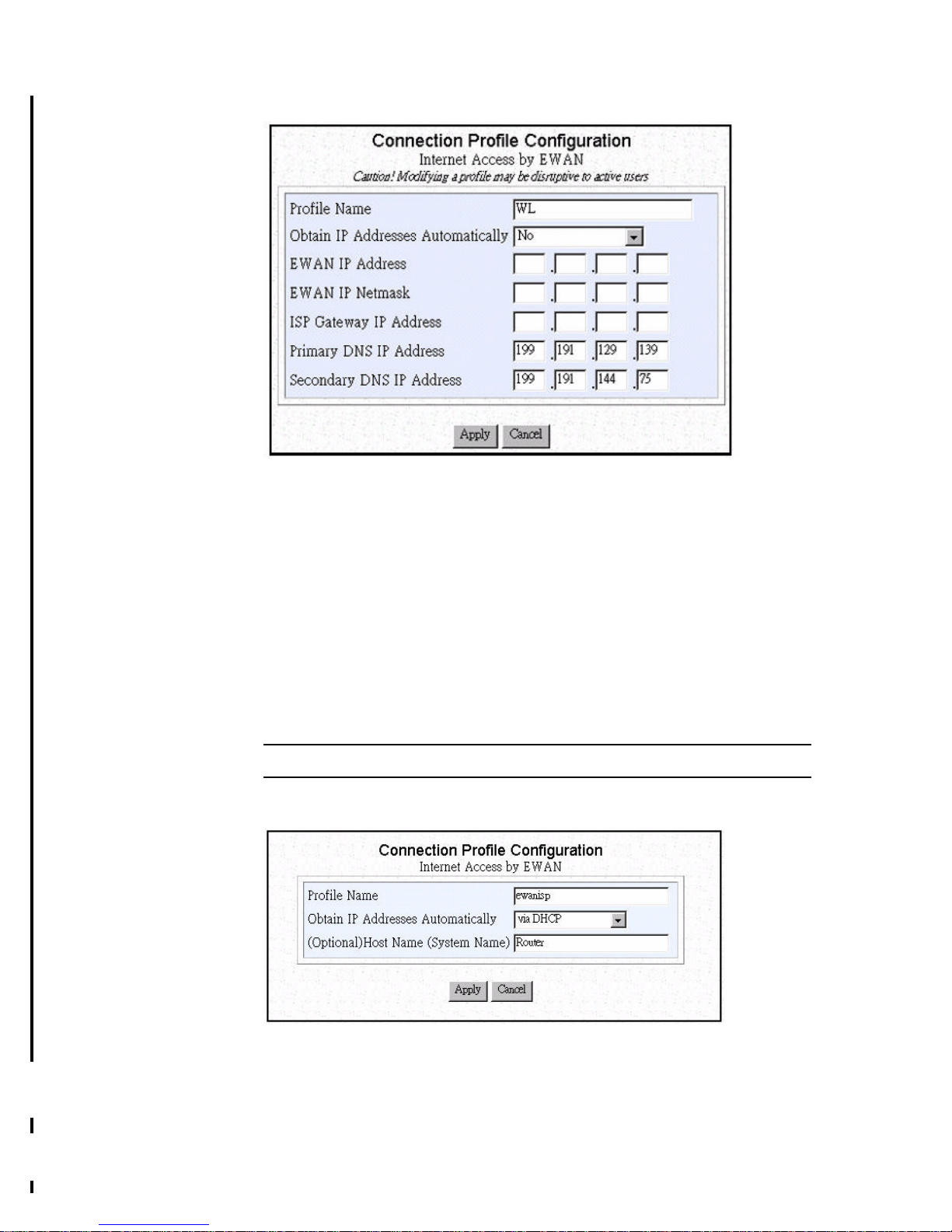
Enter the following information:
Profile Name: the name that you will use to identify this Internet access
profile.
Obtain IP Addresses Automatically: Please specify IP address ,
netmask,gateway and domain name server assigned by ISP.
EWAN IP Address: the IP address of your EWAN.
EWAN IP Netmask: the IP Netmask of your EWAN.
ISP Gateway IP Address: the IP address of your ISP Gateway
Primary DNS IP Address: the IP address of primary domain name server
Secondary DNS IP Address: the IP address of secondary domain name
server
Note: After configuring each item, please go to step 4.
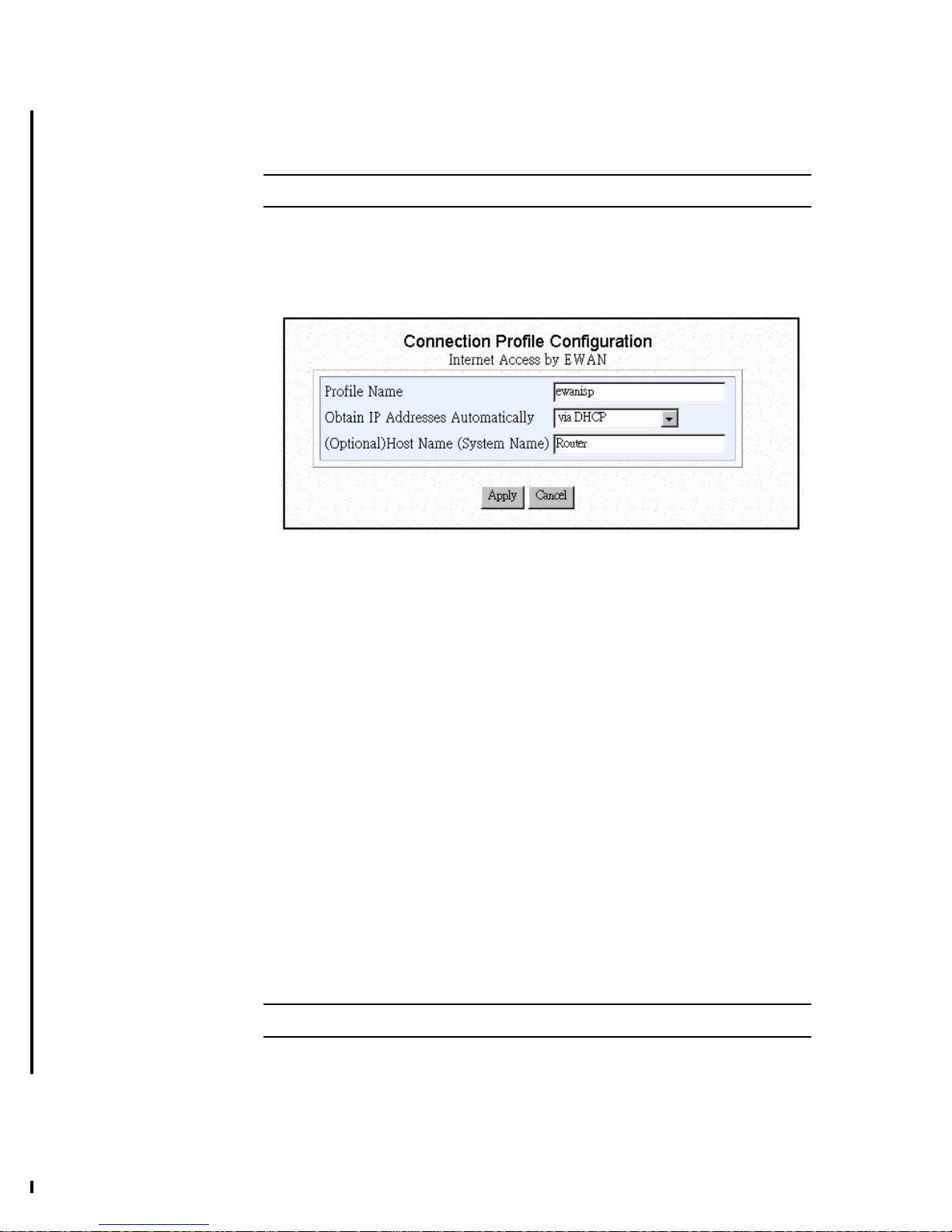
Step 2 If you choose “via DHCP” the following items will appear.
Please enter the following information:
Profile Name: the name that you will use to identify this Internet access
profile.
Obtain IP Addresses Automatically: get the IP address via DHCP
Page 22
3-8
(Optional) Host Name (System Name): the Host Name provided by your
system.
Note: After configuring each item, please go to step 4.
Step 3 If you choose “via PPP over Ethernet” the following items will appear.
Please enter the following information:
Profile Name: the name that you will use to identify this Internet access
profile.
Obtain IP Addresses Automatically: Some DSL-based ISPs use PPPoE
to establish communication with end-users.
ISP Account Name: the username of your ISP account
ISP Account Password: the password of your ISP account
(Optional) Service Name: the Service Name provided by your ISP, if one
is required, otherwise, leave it empty
(Optional) Access Concentrator Name: the Access Concentrator Name
provided by your ISP, if one is required, otherwise, leave it empty
Idle Timeout(0-3600 seconds): The default value of the idle timeout is
120 seconds. It represents the number of seconds of inactivity over the
connection: when this value is reached, the Broadband Router will
disconnect the call. You can change the idle timeout value to anything
between 0 to 3600 seconds. But if you select 0, the connection will never
time out.
(Optional) Host Name (System Name): the Host Name provided by your
system.
Note: After configuring each item, please go to step 4.
Step 4 Click APPLY or APPLY and Test
Page 23

3-9
Note: When you click Apply or Apply and Test , the Broadband Router connects
to your Internet Service Provider. Watch the Message Window for any messages. If
the test is successful, your users will be ready to access the Internet. If not, the
Broadband Router will try to give you enough information to let you know why the
connection is not successful.
If Apply or Apply and Test is successful, users on your LAN can now start to
access the Internet. However, it is required that these devices have also been
configured to obtain IP addresses automatically, as described in Chapter 2. Users may
need to re-boot their computers in order to obtain the DNS information obtained
dSetting Up Internet Access with Advanced Features
When you check the box, Internet Access with Advanced Configuration on the
ARM Customization Screen, additional configuration choices become available
during your ARM configuration session. For example, some of these choices will
allow you to , modify the Broadband Router private IP address, and/or assign a
public IP address.
Note: After you change the private IP address of a Broadband Router , all devices
on your LAN will no longer be able to communicate with it. You need to reboot all
devices in order for them to be able to communicate with the Broadband Router
again. (Rebooting each device will cause them to acquire a new private IP address
and default Gateway within the re-configured network from the Broadband Router).
In order for the Broadband Router to support public servers for access by the
Internet, you need to create a “public” network on your LAN. This can be done in one
of two ways. Use Network Address Translation to map the application to be accessed
from the Internet. This procedure is described in the section “Port Address
Translation” in Chapter 5, or acquire public IP addresses., from your ISP and assign it
to the router and to the public devices on your LAN. The procedure to assign a public
IP address to the router is described below.
Note: The ARM Customization screen displays the very first time you invoke the
ARM tool. To return to this screen, select Customize User Interface from the ARM
Menu.
Modifying Public and Private IP Addresses
You can use the IP screen to enter a public IP address, modify a private IP address,
modify or enter DNS addresses configure WINS addresses and node type or enable or
disable the DHCP service.
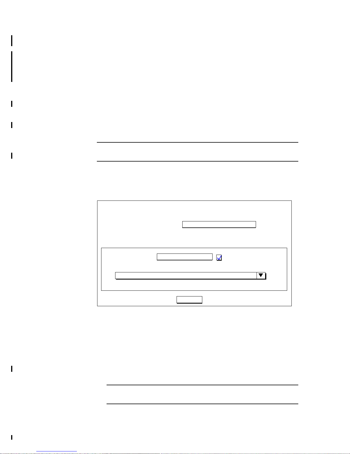
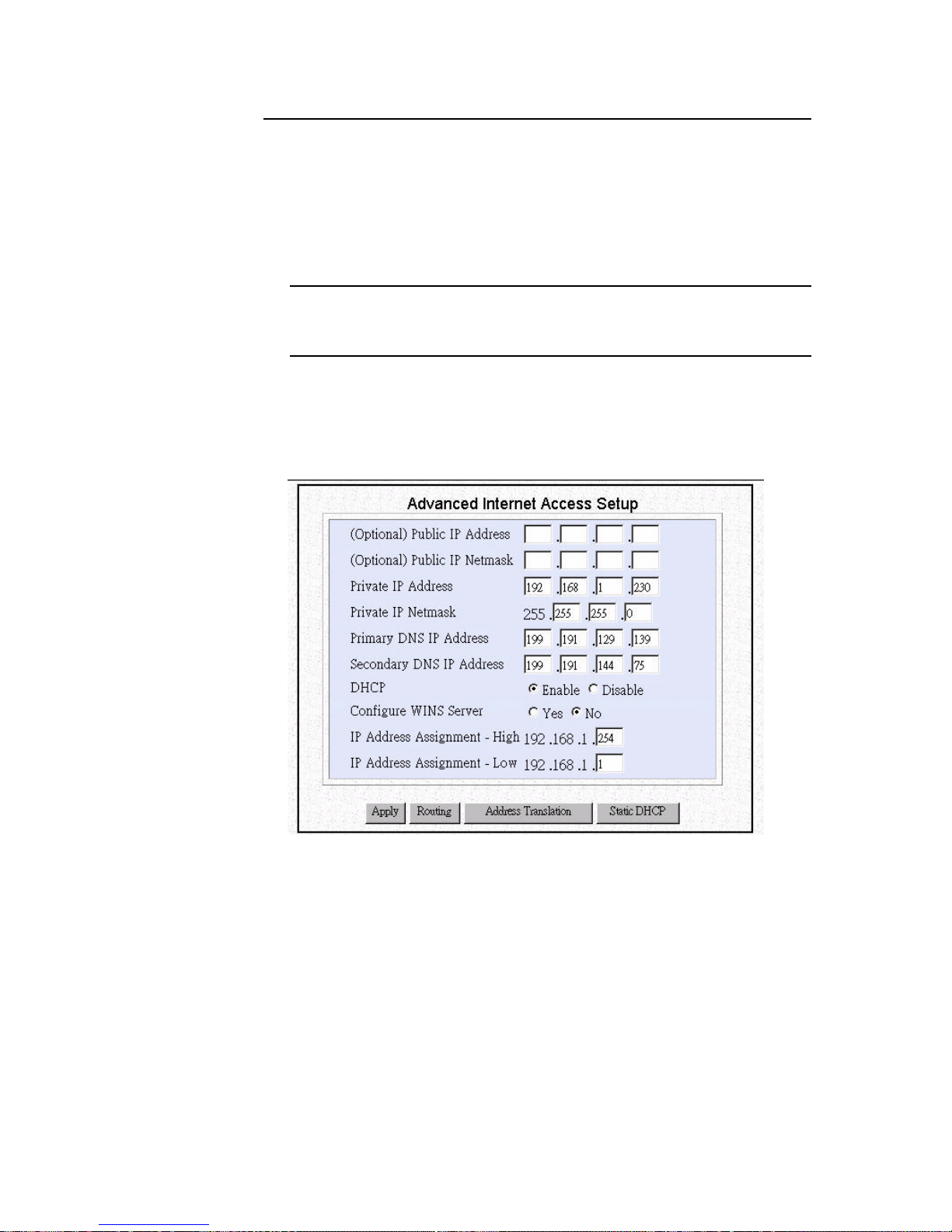
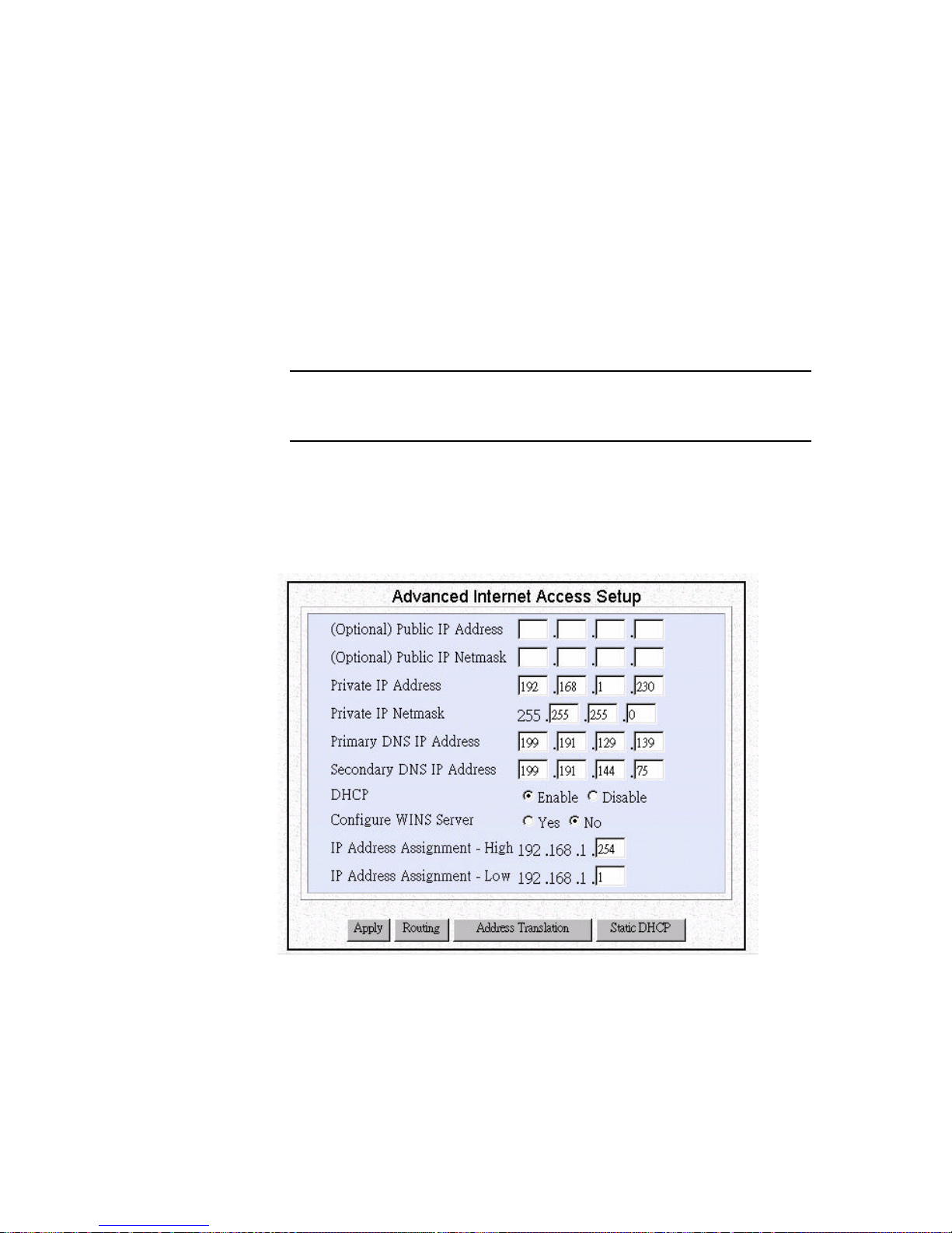
Step 1 Select IP from the ARM menu:
Configuration - Advanced IP
Page 24
3-10
Then the following screen displays:
Step 2 Enter the following information:
Note: To install publicly addressed servers on your network (e.g., Web or ftp
servers), you need to apply for an IP address for each server plus one for the LAN
port of the Broadband Router. All these public IP addresses have to belong to the
same IP network.
Public IP Address: the public IP address for the LAN interface on the
Broadband Router.
Public IP Netmask: the network mask for the public network address on
your LAN.
Private IP Address: the private IP address for the LAN interface on the
Broadband Router. The default private IP address is 192.168.168.230. If
you want to create your own private network through other Broadband
Router at remote office locations, you need to make sure that each
Broadband Router on each LAN is assigned an address in a unique private
IP network .
Note: Once you change the private IP address (e.g., from the default of
192.168.168.230 to 192.168.167.230) either from the browser or through a telnet
session (which is based on the IP address), you will no longer be able to
communicate with your Broadband Router. To reconnect, you need to re-boot
LAN Interface
Public IP address Private IP address
Private
workstations on
Public computers
on your public
network
EWAN Interface
(IP address usually assigned by ISP)
Internet
your private
network
Page 25

3-11
your computer. This is so that your device will re-acquire the IP address and
default Gateway from the Broadband Router based on the new private IP
network. Your device will then again be able to communicate with your
Broadband Router. For the same reason, all devices on the LAN need to be
restarted before they can access the Internet again.
Private IP Netmask: the network mask for your private network. Its
value is 255.255.255.0 and cannot be changed.
The Broadband Router private address of 192.168.xxx.yyy is called a
“Class C” IP address. This means that changing xxx will change the
network while changing yyy will assign a different address in the same
network.
Primary DNS IP Address: the IP address of the primary Domain Name
Server (DNS). If properly configured, when a computer re-boots and
acquires the IP address from the Broadband Router, the IP addresses of
both the primary and the secondary DNS server will be provided to
requesting client workstations. This field will reflect the DNS addresses
acquired from the ISP and will be used to assign to requesting DHCP
clients (see below). You may change this address if you want another
address to be assigned instead. The Broadband Router will pave any
manually configured DNS addresses.
Secondary DNS IP Address: the IP address of the secondary Domain
Name Server.
Note: When a Broadband Router connects to the ISP, it will automatically be
assigned the IP address of a primary Domain Name Server (DNS), as well as the
IP address for a secondary DNS.
DHCP: this enables or disables the Broadband Router Dynamic Host
Configuration Protocol (DHCP) feature. If you want the Broadband
Router to act as a DHCP server and assign private IP addresses to any
requesting DHCP client, make sure DHCP is enabled (the default). When
enabled, the Broadband Router will provide an IP address, network mask,
gateway address (the Broadband Router private IP address), DNS
addresses WINS server address and windows node type to any
workstations on the local area network that are configured as a DHCP
client.
Note: Devices on your network that are configured with public IP addresses
are not DHCP clients. Therefore, you need to assign their IP addresses, network
mask, default gateway’s IP address, primary and secondary DNS IP addresses
manually.
MAC Address cloning: Some ISPs may require you to register the MAC
address of your card/adapter, please refer to the CLI manual.
Page 26
3-12
Setting the System Time
The Broadband Router maintains a real-time clock which is automatically set to the
local time of the management PC the first time a connection is made to ARM. To
modify the Broadband Router clock, follow the steps below.
The time is used to provide time stamps for Connection Log and System Log entries.
It is also used for determining Internet access restrictions (see the section, “Setting
Internet Access Time Restrictions”, below).
Since the Broadband Router does not contain a backup battery for the real-time clock,
the time will not be maintained across system resets or power cycles. Therefore, after
a reset or power cycle, the clock will not be correct. To set the clock once again,
simply log on to ARM. Note that the time zone and daylight savings time indicator
are saved across power cycles.
Note: The System Time menu choice will not be shown if only Basic Internet
Access was selected in the ARM Configuration screen
To view or change the system time settings, select System Time from the menu:
Configuration - Advanced - System Time
The following screen displays:
Step 1 Select the Time Zone of the router location from the selections in the drop-
down list (if needed).
Step 2 Check the Daylight Savings Time box, if appropriate. Note that the setting
for Daylight Savings Time does not change automatically. Setting the
system time between Standard Time and Daylight Savings Time must be
done manually.
Step 3 Click Apply. The Broadband Router time and Time Zone is now reflected
in the “Current Router Time” box.
Note: The proposed Router Time is always based upon the time set in the
management PC, adjusted for the selected Time Zone.
Current Router Time
04/13/99 16:20:09
Proposed Router Time
System Time Setting
APPLY
04/13/99 16:20:09
Daylight Savings Time
and Time Zone: GMT -8, Daylight Saving Time
Select to Change the Time Zone for the Router Location
(GMT-08:00)Pacific Time(US & Canada); Tijuana
Page 27
3-13
Setting Internet Access Time Restrictions
For cost, security and efficiency reasons, you may want to adjust the times when the
Broadband Router will be allowed to automatically connect to the Internet. A simple
setup screen is used to enter the days of the week and the hours of the day during
which Internet access is allowed. The Broadband Router will not connect to the
Internet outside of the configured times.
In order for this feature to be effective, the Broadband Router must be configured for
the current local time. To do this, see the section, “Setting the System Time”, above.
Note, however, that if for some reason the Broadband Router is reset or powercycled, the previous time setting will be lost. Until you once again set the time, the
Broadband Router will either allow Internet access or not, depending upon a setting
which is configured below.
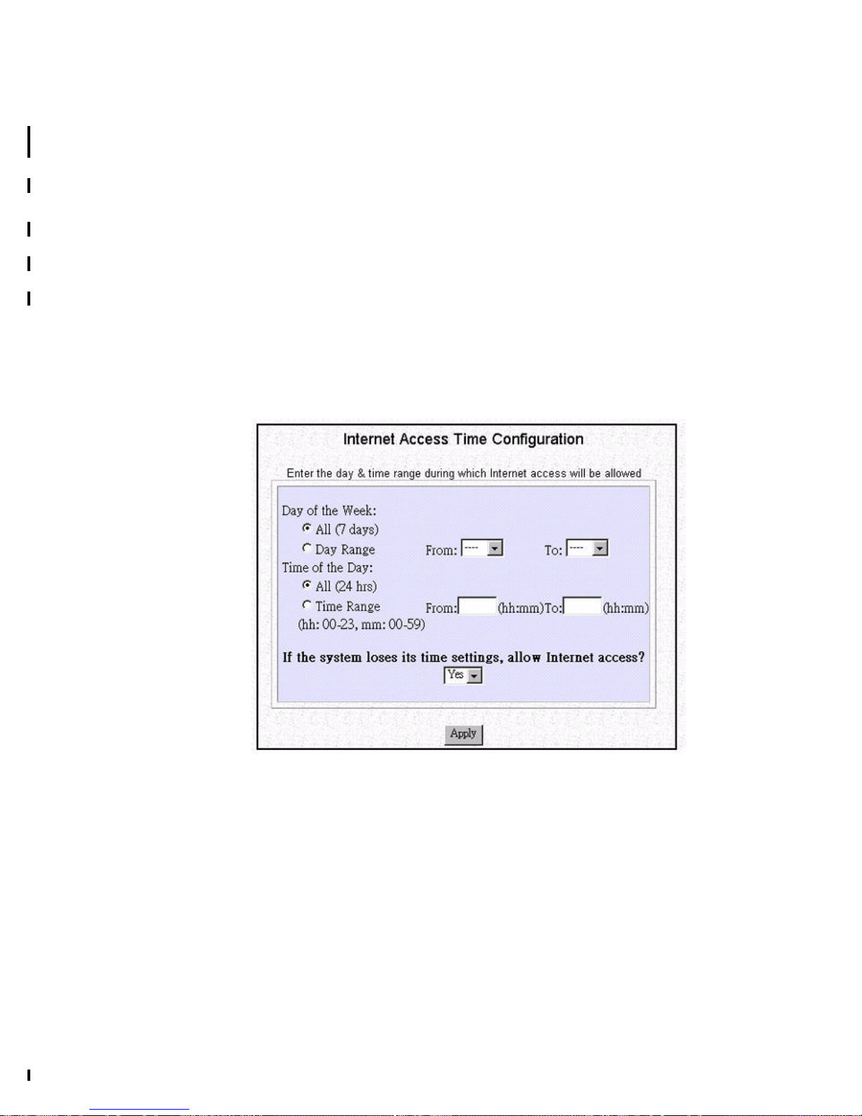
To view or change Internet access time restriction settings, select Internet Access
Time from the menu:
Configuration - Internet Access Time
The following screen is displayed:
Step 1 Set the days of the week during which Internet access is allowed. Select
Day Range if you want to specify a range of days. If you select All,
Internet access will be allowed every day.
Step 2 Set the time during which Internet access will be allowed. Not that this
setting is based upon a 24 hour clock. Select Time Range to enter a
consecutive period of time between which Internet access is allowed. If
you select All, Internet access will be allowed from midnight to midnight
on the days selected in Step 1.
Step 3 Enter the default setting for Internet access if the router is power-cycled or
reset. If you enter “Yes” (the default), then Internet access will be allowed
unconditionally until the clock is set. If you enter “No”, then Internet
access will not be allowed until the clock is set.
Step 4 Click Apply to enable your settings.
Page 28

4-1
4
4 Advanced Configuration
This section covers advanced configuration of the Broadband Router. These functions
include:
• Configuring and Using Port Address Translation
• Static DHCP Assignments
• Creating Virtual Private Networking Connections
• Using Packet Filtering
• Configuring IP Settings
• Configuring IPX Settings
• Configuring Bridging Settings
Configuring and Using Port Address Translation
The Port Address Translation (PAT) feature of Broadband Router is a powerful and
economical way of allowing Internet access to public machines on your LAN without
applying for or configuring public IP addresses. It complements single IP address
translation so that not only does it give users the benefits and administrative
simplicity of a using a single IP address ISP account, it also provides the flexibility of
a configurable combination of secure, privately addressed workstations and port
mapped publicly accessible applications.
You have already read about private addressing on your LAN in Chapter 1. PAT
extends this concept to provide a way to specify the applications on LAN which you
want Internet users to be able to access. This is done by configuring the router to reroute an Internet packet that Broadband Router receives from the Internet into the
TCP or UDP port that the application uses on the privately addressed LAN machine
that is actually running that application. In this manner, a privately addressed PC on
your LAN that is running a Web Server, for example, may be accessed from the
Internet by configuring the Broadband Router to translate all packets addressed to its
public address containing the destination port 80 (the standard HTTP port), to a
privately addressed NT Server, perhaps, which is running a Web Server application.
The remote Internet user never knows about, nor can access, any other services
running on the actual PC with which he or she is communicating.
In this way a PC application is “mapped” to a port on the Broadband Router.
Note: When port 80 (HTTP) and/or port 23 (telnet) is mapped to a private IP
address, special consideration must given for remote administration of the Broadband
Router since those are the ports which are normally used for the browser-based ARM
interface , respectively.When port 80 is re-mapped, remote administrators must remap port 80 on the router to another port. Thus, the remote administrator may then
invoke ARM using the re-mapped port. Note that, using the extended URL format, if
ARM were re-mapped to port 8080, the URL for accessing this location is http://
192.168.168.230:8080.When port 23 is re-mapped, remote administrators must re-
Page 29
4-2
map port 23 on the router to another port.
Configuring Port Address Translation
Each application that is to be mapped requires an entry to be configured in the
Address Translation Table. To access this table perform the following steps:
Step 1 Select Internet Access with Advanced Configuration in the ARM
Configuration screen.
Note: The ARM Configuration screen is displayed the very first time you run
the ARM software. To return to this screen, select Customize User Interface
from the menu.
Step 2 Select IP from the Menu:
Configuration - Advanced - IP
Step 3 At the bottom of the System IP Configuration screen press the button
marked Address Translation.
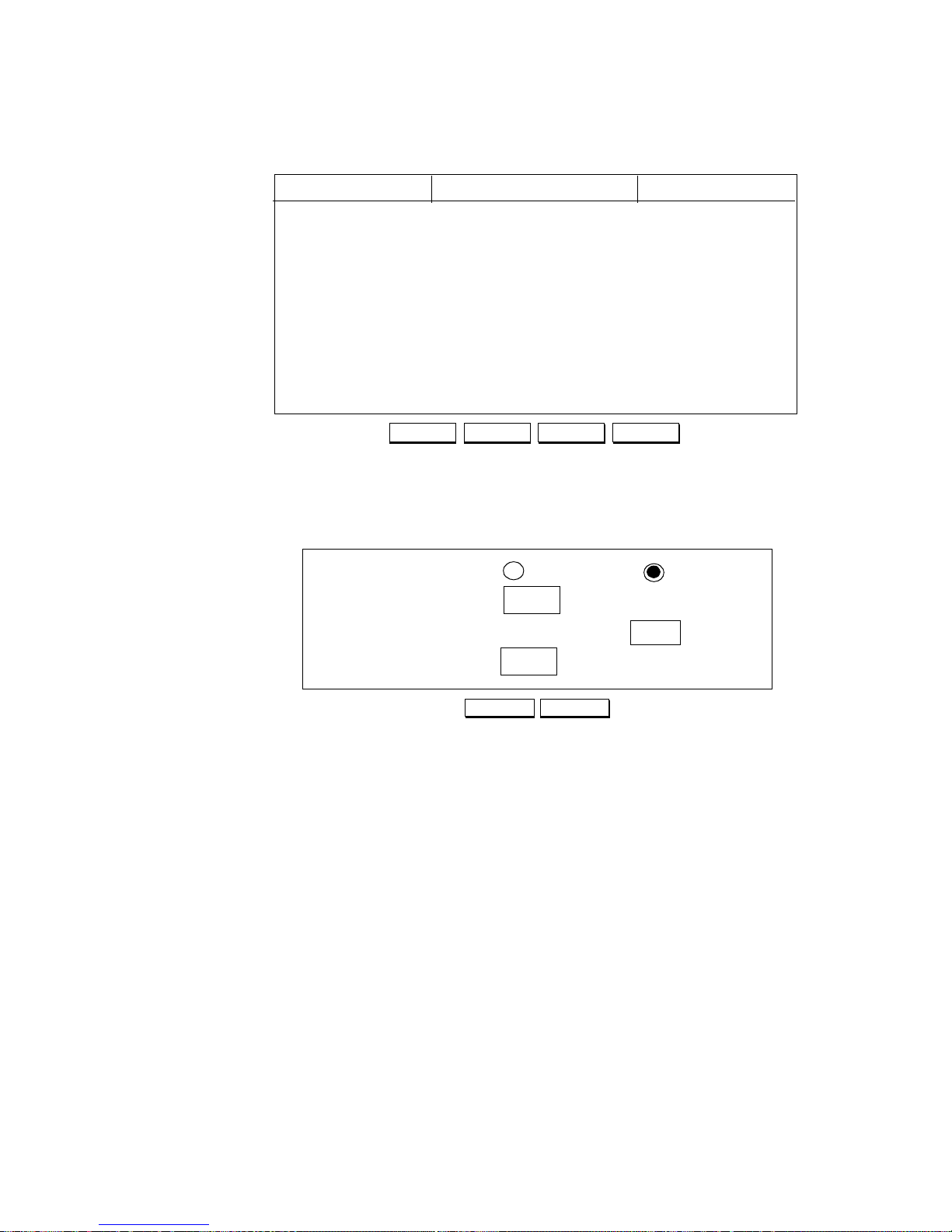
Step 4 Add an entry to the IP Address Translation Table by clicking the Add but-
ton at the bottom of the table.
Page 30
4-3
Step 5 From Add a Static Entry screen configure the following information:
Add Address Translation: Select the type of entry being configured.
There may be one and only one Default Entry configured in the router.
The Default Entry is a device to which Internet requests will be sent if no
other match is found in the Address Translation Table. If you select
Default Entry, the Private Port Number selection does not appear.
The Static Entry selection is used to define a device which will receive the
request whose target port number is specified in Public Port Number.
Public Port Number: This is the TCP or UDP port contained in the
received IP packet from the Internet. This port number will be translated
into the port number specified in the Private Port Number field.
Private IP Address: The private address specified here will be the
translated destination of the IP packet received from the Internet.
Private Port Number: This is the port number on the device with the IP
address specified in Private IP Address to which the IP packet will be
sent.
Step 6 Press Apply to enter the configured Address Translation Table entry.
Step 7 The screen will revert to the Address Translation Table display with the
new entry added. From this screen, you may select an entry and then press
Add
IP Address Translation Configuration
Private IP AddressPublic Port Number Private Port Number
Edit
Static Address Translation
123 192.168.168.101 1201
Delete Refresh
APPLY
IP Address Translation Configuration
CANCEL
Static Entry
Default Entry
Add a Static Entry
Add Address Translation
Public Port Number
Private IP Address
192 168
122
. .
168
.
236
Private Port Number
8236
Page 31
4-4
Edit to edit the selected entry, press Delete to delete the selected entry,
press Refresh to refresh the display, or press Add to add another entry.
Static DHCP Assignments
In certain LAN environments, it is desirable for some PCs to be assigned the same
address each time it queries a DHCP server. Broadband Router is capable of
configuring up to 20 such PCs for static assignments.
Each PC that is to be assigned a static address requires an entry to be configured in the
DHCP Static Assignment Table. To access this table perform the following steps:
Step 1 Select Internet Access with Advanced Configuration in the ARM
Configuration screen.
Note: The ARM Configuration screen is displayed the very first time you run
the ARM software. To return to this screen, select Customize User Interface
from the menu.
Step 2 Select IP from the Menu:
Configuration - Advanced Features - IP
Step 3 At the bottom of the System IP Configuration screen press the button
marked Static DHCP.
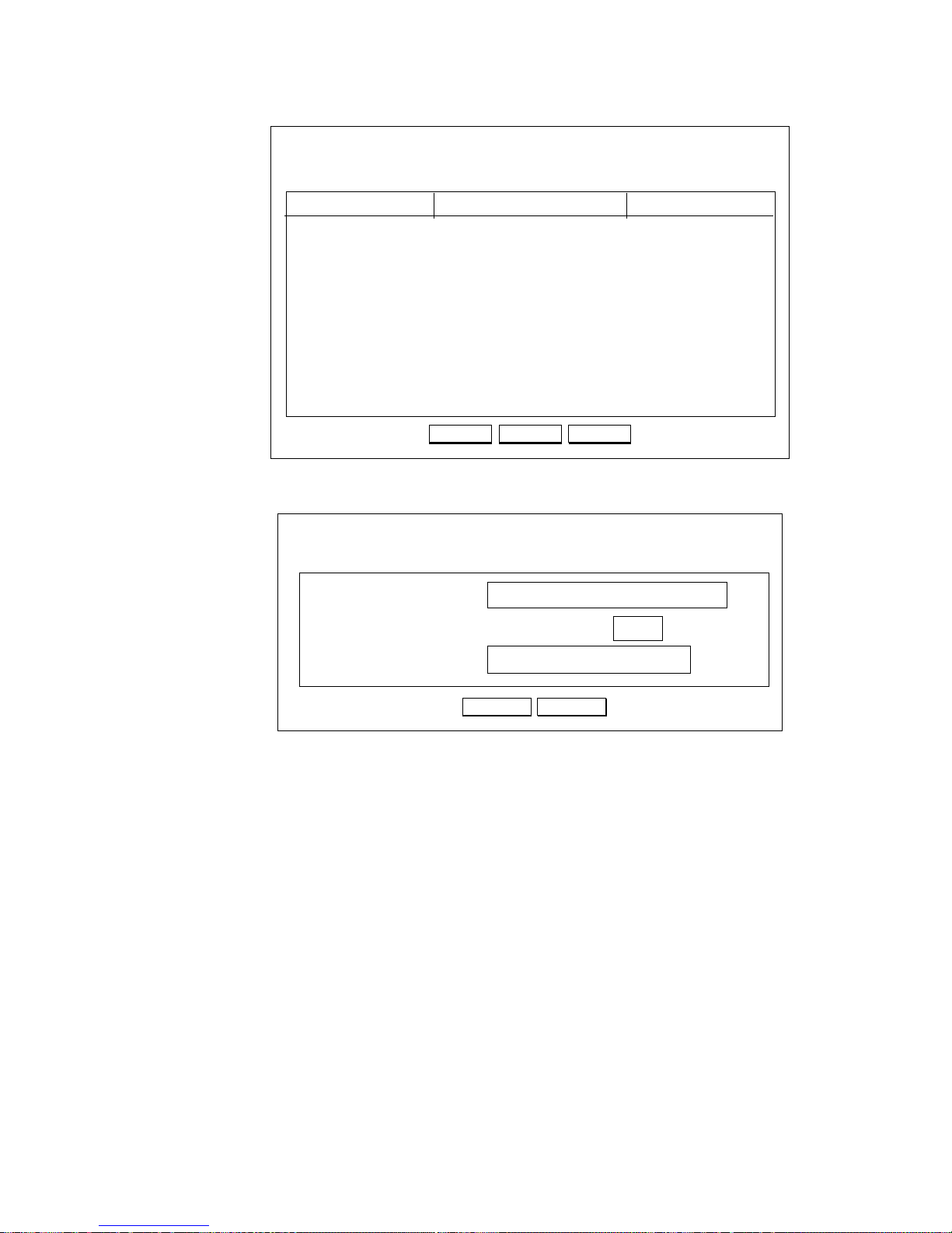
Step 4 Add an entry to the DHCP Static Assignment Table by clicking the Add
Page 32
4-5
button at the bottom of the table.
Step 5 From the Add a Static Entry screen configure the following information:
Name: Enter a convenient display name for this resource.
IP Address: The IP address to be consistently assigned to this device
MAC Address: The hardware address associated with the Ethernet
adapter which is permanently assigned to this machine. Note that dashes
must separate each pair of hexadecimal digits.
Step 6 Press Apply to enter the configured DHCP Static Assignment Table entry.
Step 7 The screen will revert to the DHCP Static Assignment Table display with
the new entry added. From this screen, you may select an entry and then
press Edit to edit the selected entry, press Delete to delete the selected
entry, or press Add to add another entry.
Creating VPN Connection Profiles
Before continuing on with this section, be sure you’ve reviewed the section,
“Accessing Servers from the Public Network” in Chapter 1.
Also, make sure you have properly configured the Internet access profile( as detailed
in Chapter 3) before attempting to send traffic through VPN tunnels.
Add
DHCP Configuration
IP AddressName MAC Address
Edit
Static Assignment Table
Bing 192.168.168.95 00-aa-00-62-c6-09
Delete
APPLY
DHCP Configuration
CANCEL
Add a Static Entry
Name
IP Address
192 168
122
. .
168
MAC Address
00-40-05-35-db-4a
Julia
.
Page 33
4-6
Note: To configure VPN connection, you must have the VPN feature key installed.
When you set up your VPN, keep in mind that the VPN connection (the “tunnel”)
emulates an actual hardware wide area network port. After setting up your VPN
tunnel, you can create a connection profile to allow access to and from a remote site.
VPN connections are created automatically as a result of a reference by a LAN user to
a resource reachable through a VPN connection.
To Configure VPN Remote Office Access Profiles
In order to set up access to and from a remote site, be sure to configure both ends of
the VPN tunnel appropriately (the remote router and the local router). Broadband
Router supports for the Layer 2 Tunneling Protocol(L2TP), which was the original
open standard for Vitual Private Networking. If you selected Access to/from
Remote Site from the ARM Configuration screen, follow the steps in this section.
Note: When communicating with a remote office, the private IP network must be
different on both sides of the connection. To do this, follow the steps indicated in the
section, “To Configure Advanced IP Settings”, below.
Step 1 Select Access to/from Remote Site in the ARM Configuration screen.
Note: The ARM Configuration screen is displayed the very first time you run the
ARM software. To return to this screen, select Customize User Interface from the
menu.
Step 2 Configure a VPN tunnel. Select VPN-L2TP Tunnel from the menu:
Configuration - WAN Interface - VPN-L2TP Tunnel
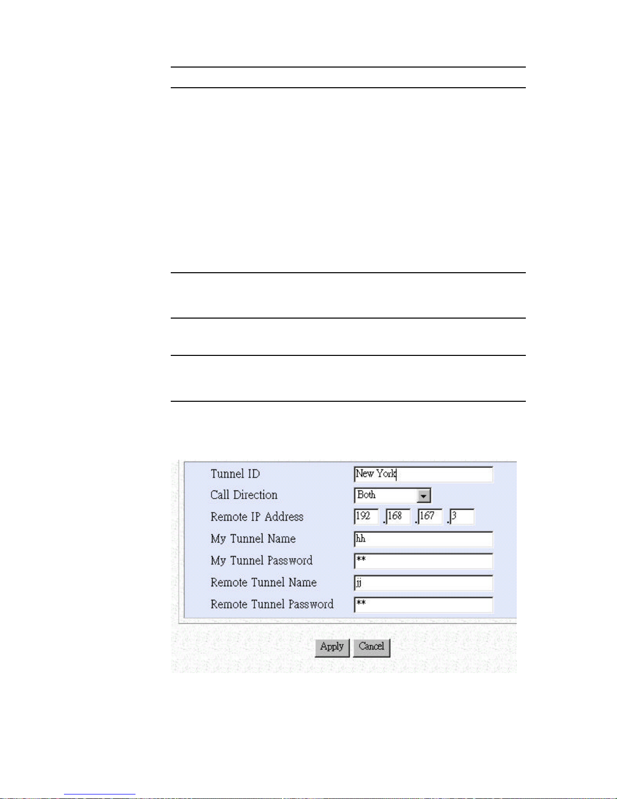
Step 3 Enter the following information:
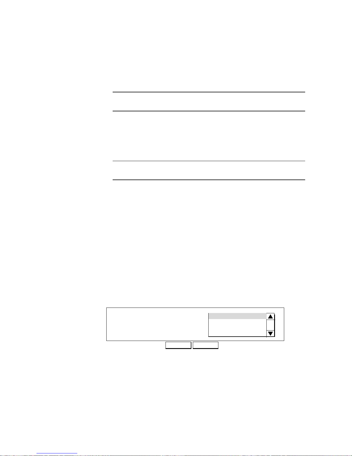
Tunnel ID: a ID by which you will refer to this VPN tunnel.
Call Direction: the direction of the call in the tunnel. If the remote site
Page 34
4-7
will always be creating the tunnel, select Incoming Only. If the
Broadband Router will always initiate the connection to the remote site,
select Outgoing Only. Select Both if either side can initiate the
connection.The default setting is Both.
Remote IP Address: Key in your remote side IP address when you set
Call Direction to Both or Outgoing
Note: If you set Call Direction to Incoming Only, the Remote IP Address
field does not display.
My Tunnel Name: the name that the remote system will use to recognize
your network.
My Tunnel Password: the password the remote system will use to
authenticate your system.If the remote site does not require tunnel
authentication, leave this field blank.
Note: Make sure the remote site is configured with your Tunnel Name (and
Tunnel Password, if used).
Remote Tunnel Name: the name of the remote network that is dialing in.
Remote Tunnel Password: the password that your Broadband Router
will expect to see from the remote system. If you do not require tunnel
authentication, leave this field blank.
Step 4 Click APPLY.
Set up a VPN Connection Profile
Step 1 Set up a VPN Connection Profile. Select Connection Profiles from the
Menu:
Configuration - Connection Profiles
Step 2 When you select Connection Profiles, the Connection Profile Summary
screen appears only if you have existing Connection Profiles.
Step 3 Select New from the pull-down menu, and click NEXT. The Interface
Select a Connection Profile
DELETE
Connection Profile Summary
NEXT
New
New York
Page 35

4-8
Configuration screen appears. For example:
Note: If VPN-L2TP is selected as the interface, the Remote Office Access is the
only Configuration Type displayed.
Step 4 Select VPN-L2TP as the interface, and check Remote Office Access
from the list of configuration types.
Step 5 Click NEXT to continue. The Connection Profile Configuration screen
appears.
Step 6 Enter the following information:
Profile Name: the name that you will use to identify this remote office
dial-in/dial-out profile.
Call Direction: the direction of the call in the tunnel. If the remote site
will be dialing in, select Incoming Only. If the Broadband Router will be
dialing out to the remote site, select Outgoing Only. Select Both if either
side can initiate the connection.The default setting is Both.
Note: If you set Call Direction to Incoming Only, the My Account Name
and My Account Password fields do not display. If you set Call Direction to
Outgoing Only, the Remote Account Name and Remote Account Password
fields do not display
My Account Name: the name that the remote system will use to recognize
your network.
My Account Password: the password the remote system will use to
authenticate your system
Select an Interface
NEXT
Interface Configuration
VPN-L2TP
Select a Configuration Type
Remote Office Access
My Account Name
My Account Password
Connection Profile Configuration
Incoming Authentication CHAP/PAP/MS-CHAP
Remote Account Name
Remote Account Password
APPLY and TEST CANCEL ADVANCED
Remote Office Access by VPN-L2TP
VPN-L2TP Tunnel
NewYork
Call Direction
Both
Profile Name
Page 36
4-9
Note: Make sure the VPN Connection Profile at the remote site is configured
with your Account Name and Account Password.
Remote Account Name: the name of the remote network that is dialing
in.
Remote Account Password: the password that your Broadband Router
will expect to see from the remote system.
VPN-L2TP Tunnel: the VPN Tunnel you will use for this profile. This is
one of the tunnel configurations set up earlier.
Step 7 Click APPLY and TEST when you are done, or select Advanced to enter
advanced options.
Advanced Options Setup
Note: The IPX options shown in this screen only appear if you selected Share
NetWare (IPX) Resource on the ARM Configuration screen.
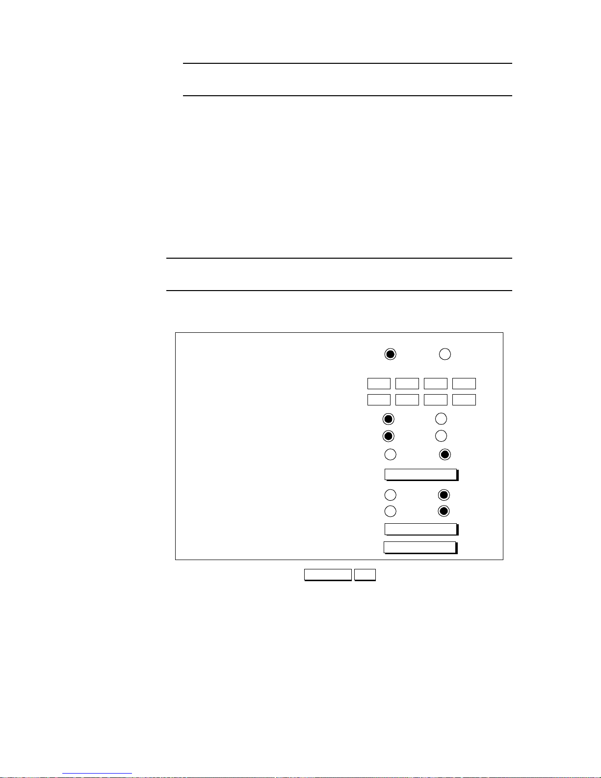
Step 1 Enter the following information:
Enable IP: allows IP routing over a connection using this profile.
Remote IP Address: the IP address of a destination computer on a
network reachable through this connection.
Remote IP Netmask: the IP subnet mask of the Remote IP Address.
Enable IPX: allows IPX routing over a connection using this profile.
IPX RIP/SAP: enables or disables IPX Routing Information Protocol and
Service Advertising Protocol.
Connection Profile Configuration
CANCEL OK
(Optional) Remote IP Address
(Optional) Remote IP Netmask
Remote Office Access by VPN
. . .
. . .
IPX RIP/SAP
Enable
Disable
Enable IPX
Yes
No
Encryption Key
Enable Bridging
DisableEnable
Set as IPX Default Route
NoYes
Enable Encryption
DES
No
Confirm Encryption Key
(Optional) Remote IPX Network Number
Enable IP
Yes
No
Page 37

4-10
Set as IPX Default Route: specifies whether this connection is used as
the default IPX route if no other route for an IPX packet can be found in
the routing table.
Remote IPX Network Number: the IPX network number of a network
reachable through this connection. If you set this connection as the default
IPX route, this field is not displayed.
Enable Bridging: enables or disables bridging to bridge other protocols,
for example, SNA, Appletalk, and NetBEUI.
Enable Encryption: allows DES encryption. If you select DES
encryption you must enter a DES Encryption key.
Encryption key: the DES encryption key used by other systems to
establish contact with your system. This must be a hexadecimal number
(0-9, a-f) with up to 14 digits, depending upon the strength of encryption
licensed for your site.
Confirm Encryption key: re-enter the DES encryption key to confirm its
correct entry.
Note: For security reasons, encryption options only appear if you are
connected to the Broadband Router over a local LAN and if encryption is
enabled on your system.
Step 2 Click OK.
Step 3 Click APPLY.
Packet Filtering
This section describes the packet filtering feature.
Note: Packet filtering is a sophisticated feature that can substantially impact your
Broadband Router operation. Therefore be sure that you fully understand the
description in this chapter before you start to configure and use this feature, since if
you make any mistakes, it may produce drastic and potentially undesired results.
A Packet Filtering Overview
The Broadband Router already provides you with many different ways to ensure the
security of your data in your local environment. Packet filtering is a security feature
that allows you to selectively pass or throw away data traffic between your local LAN
and the wide area network (e.g., the Internet). Packet Filtering allows each IP or IPX
packet exiting a router interface to be examined for a match with a configured set of rules
and an action to be taken depending upon whether the packet statisfies any rule or not.
In the browser manager, a set of rules may be configured over any existing interface
as represented by a WAN profile. To configure a set of rules for packets exiting the
LAN interface (in addition to any WAN interface), you must use the Filtering
commands in the Command Line Interface. If the contents of the packet do not match
any rule for that interface, then the packet is either forwarded or discarded, depending
upon the filter default for that interface. Otherwise, the exception action is taken, i.e.,
the packet is discarded or forwarded, the opposite of the default action.
The Broadband Router maintains separate filtering tables for IP and IPX traffic.
These filters are configured separately. Configuration commands allow you to define:
Page 38

4-11
- each and every IP or IPX packet to be inspected to determine if it should be
allowed or disallowed to be transmitted over a WAN interface alternatively.
Due to the conflicting nature of allow and disallow, only one of the above two
choices can be made for each WAN interface. After the choice is made, you can
define selection rules to “select” which packets will be allowed (or disallowed).
Each packet selection rule consists of
- an IP protocol and set of local IP addresses/ports or an IPX Packet Type and
a set of local IPX network number(s), node(s) and socket(s)
- a set of remote IP addresses/ports or remote IPX network numbers/nodes/
sockets
The following table indicates the types of values that may be configured for each rule
condition.
Page 39

4-12
Therefore packet filtering simply defines sets of rules of what to allow or disallow
through a set of parameters highlighted below:
For IP,
remote devices with IP addresses/port numbers
are allowed (or disallowed) to communicate with
local devices with IP addresses/port numbers over
a WAN connection and using a specific IP protocol.
For IPX,
remote devices with IPX network numbers/nodes/sockets
are allowed (or disallowed) to communicate with
local devices with IPX network numbers/nodes/sockets over
a WAN connection.
Examples of packet filtering requirements are:
1. “I want to block any user in my remote office from being able to access my
local NetWare server”.
The corresponding “translated” packet rule is:
All IPX communication with my remote office is allowed EXCEPT
remote devices with Any IPX network number and Any IPX node number
and Any IPX socket which are disallowed from communicating with the local
NetWare server (identified by its IPX network number, IPX Node Number
and Any socket number over my specified remote office connection profile
Protocol
Condition
Parameter
Configuration
Formats
IP
Protocol TCP/UDP/
ICMP/IGMP/
Any
Address Single/Range/
Network/Any
Port Single/Range/
Any
IPX
Packet Type Single/Any
Network
Number
Single/Range/
Any
Node Number Single/Any
Socket Single/Range/
Any
Page 40
4-13
using any IPX packet type.
2. “I want to disallow people in the manufacturing department to access the
Internet“.
The corresponding “translated” packet rule is:
All access to the Internet is allowed EXCEPT
remote devices with the range of IP addresses in the manufacturing
department and any port number which are disallowed to communicate with
any IP address/port number over my Internet connection using any IP
protocol.
Configuring IP Packet Rules
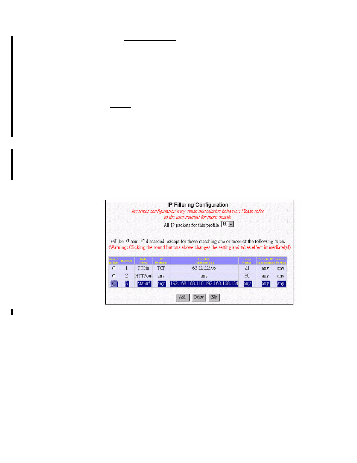
To add a new IP packet rule or to edit an existing one, select IP Filter from the ARM
menu:
Configuration - Advanced - IP Filter
Step 1 From the IP Filtering Configuration screen, select the WAN profile of
interest from the pull down menu. For example, if your only need is to
control access to the Internet, you should only select the Internet access
profile.
Step 2 Select send or discarded as the default action as desired, which is
equivalent to allow and disallow, respectively.
Step 3 If you are just starting, click Add to add a new selection rule. If you have
previously defined rules, you will see those rules shown as entries in the
rule table, and you can edit the rule by first highlighting the desired entry
in the rule table followed by clicking the Edit button.
Page 41
4-14
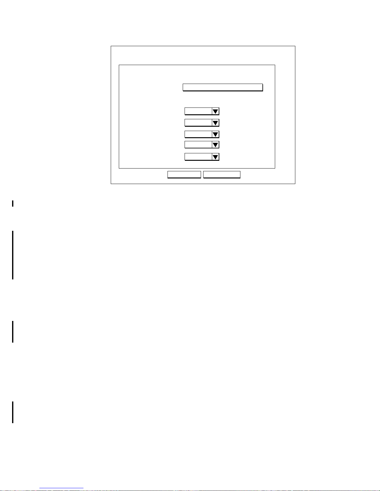
Step 4 In case of adding a new selection rule, the following screen shows:
Step 5 Enter the following information:
Rule No.: a number used for identification purposes.
Rule Name: a name by which you will refer to this rule.
Interface: the specific WAN interface to which this new selection rule
applies.
IP Protocol: the IP protocol to which this rule applies. You can select
TCP, UDP, ICMP, IGMP, or any of these protocols.
Local IP Address: the IP address(es) of the local devices this new rule
will apply to. You can select a single IP address, a range of IP addresses,
a network, or any IP addresses. The screen may change to show fields
you need to fill out accordingly. For example, if you select range, you will
also see (From) and (To) fields where you need to fill out the starting IP
address and the ending IP address.
Local Port: the port number(s) of the local devices this new rule will
apply to. See Table 4-1 for some examples of TCP/IP port assignments.
This field does not appear if either ICMP or IGMP is selected as the IP
Protocol.
Remote IP Address: the IP address(es) of the remote devices this new
rule will apply to. You can select a single IP address, a range of IP
addresses, a network, or any IP addresses. The screen may change to
show fields you need to fill out accordingly. For example, if you select
range, you will also see (From) and (To) fields where you need to fill out
the starting IP address and the ending IP address.
Remote Port: the port number(s) of the remote devices this new rule will
apply to. See Table 4-1 for some examples of TCP/IP port assignments.
This field does not appear if either ICMP or IGMP is selected as the IP
Protocol.
If you highlighted an existing entry (by selecting the Select to Edit
button) and clicked Edit instead, a similar screen will display, with all
fields already filled out by you previously. Then you can make changes as
IP Filter Configuration
Add a new rule
Rule No.
Local IP Address
CANCEL
Rule Name
Interface
Local Port
Remote IP Address
Remote Port
APPLY
1
test
any
any
any
any
WL
IP Protocol
any
Page 42

4-15
necessary.If you highlighted an existing entry and clicked Delete instead,
the corresponding entry in the rule table will be removed.
Table 4-1 TCP/IP Port Assignments
Configuring IPX Packet Rules(Optioanl)
To add a new IPX packet rule or to edit an existing one, select IPX Filter from the
ARM menu:
Configuration - Advanced - IPX Filter
Step 1 From the IPX Filtering Configuration screen, select the WAN profile of
interest from the pull down menu.
Step 2 Select send or discarded as the default action as desired, which is
equivalent to allow and disallow, respectively.
Step 3 If you are just starting, click Add to add a new selection rule. If you have
previously defined rules, you will see those rules shown as entries in the
rule table, and you can edit the rule by first highlighting the desired entry
TCP/IP
Service
Type
Port Range
BootP/DHCP 67-68
DNS 53
Finger 79
FTP 20-21
HTTP 80/8080
NetBIOS 137-139
NNTP 119
RIP 520
SMTP 25
SNMP 161-162
Sun RPC 111
Telnet 23
TFTP 69
Whois 43
Page 43
4-16
in the rule table followed by clicking the Edit button.
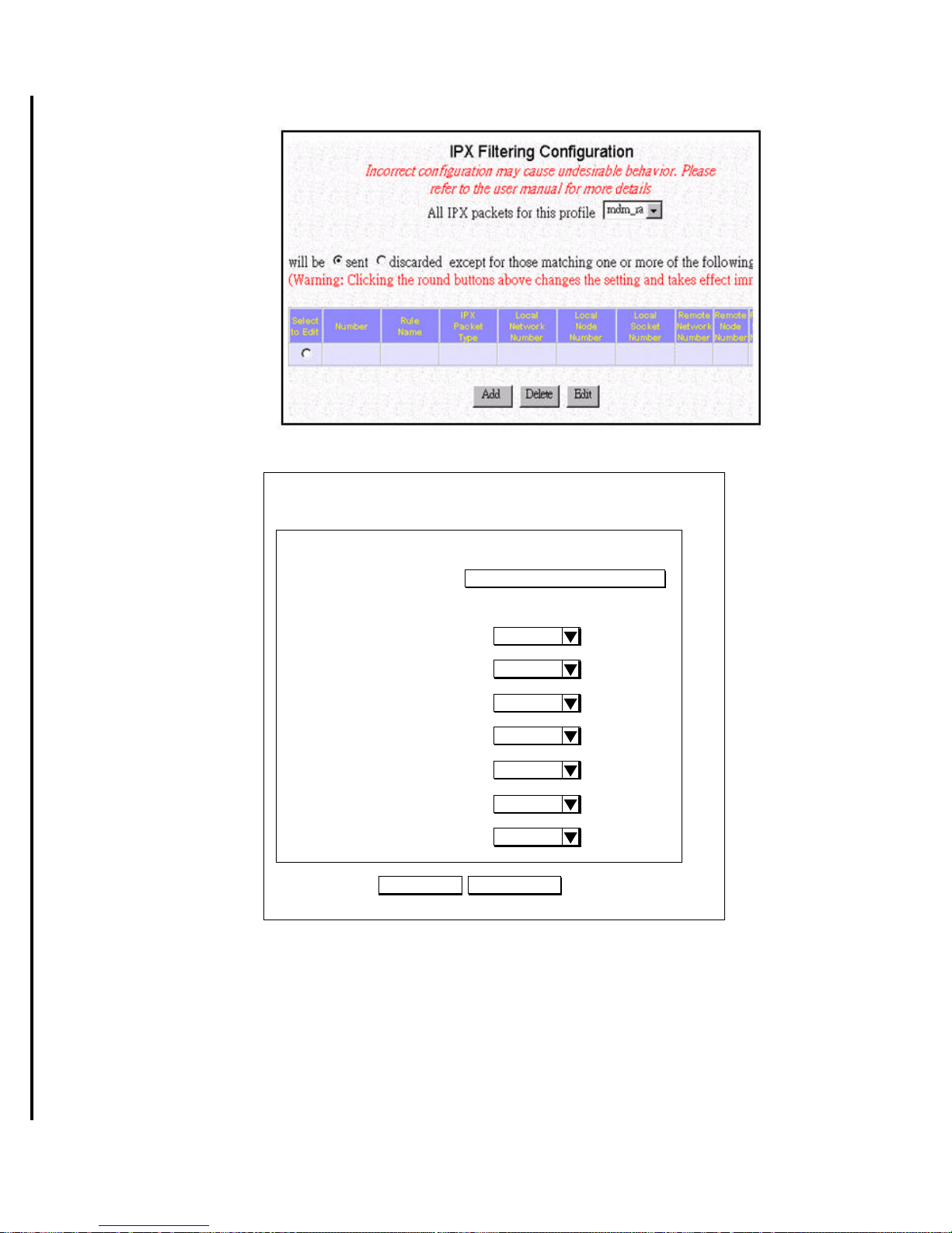
Step 4 In case of adding a new selection rule, the following screen shows:
Step 5 Enter the following information:
Rule No.: a number used for identification purposes.
Rule Name: a name by which you will refer to this rule.
Interface: the specific WAN interface this new selection rule will apply
to.
IPX Packet Type: The packet type to which the rule applies. This value is
specified as a two digit hexadecimal number. Some standard IPX Packet
Types are listed in Table 4-2
IPX Filter Configuration
Add a new rule
Rule No.
IPX Packet Type
CANCEL
Rule Name
Interface
APPLY
1
test
any
Local IPX Network Number
any
Local IPX Node Number
any
Local IPX Socket Number
any
Remote IPX Network Number
any
Remote IPX Node Number
any
Remote IPX Socket Number
any
Page 44

4-17
Local IPX Network Number: the IPX Network Number(s) of the local
devices to which this new rule applies. You can select a single IPX
Network Number, a range of IPX Network Numbers, or any IPX
Network Number. The screen may change to show fields you need to fill
out accordingly. For example, if you select range, you will also see
(From) and (To) fields where you need to fill out the starting IPX
Network Number and the ending IPX Network Number.
Local IPX Node Number: the IPX Node Number of the local device(s) to
which this new rule applies. You may select an individual Network Node
or any Network Node. An individual Network Node is entered as six pairs
of hexadecimal digits, such as 11-22-33-aa-bb-cc.
Local IPX Socket Number: the local IPX Socket Number(s) of the local
devices to which this rule applies. You can select a single IPX Socket
Number, a range of IPX Socket Numbers, or any IPX Socket Number.
This value is specified as a four digit hexadecimal number.
Remote IPX Network Number: the IPX Network Number(s) of the
remote devices to which this new rule applies. You can select a single IPX
Network Number, a range of IPX Network Numbers, or any IPX
Network Number. The screen may change to show fields you need to fill
out accordingly. For example, if you select range, you will also see
(From) and (To) fields where you need to fill out the starting IPX
Network Number and the ending IPX Network Number.
Remote IPX Node Number: the IPX Node Number of the remote
device(s) to which this new rule applies. You may select an individual
Network Node or any Network Node. An individual Network Node is
entered as six pairs of hexadecimal digits, such as 11-22-33-aa-bb-cc.
Remote IPX Socket Number: the remote IPX Socket Number(s) of the
local devices to which this rule applies. You can select a single IPX
Socket Number, a range of IPX Socket Numbers, or any IPX Socket
Number. This value is specified as a four digit hexadecimal number.
If you highlighted an existing entry (by selecting the Select to Edit button) and
clicked Edit instead, a similar screen will display, with all fields already filled out by
you previously. Then you can make changes as necessary.
If you highlighted an existing entry and clicked Delete instead, the corresponding
entry in the rule table will be removed.
Packet Type
Hexadecimal
Value
Unknown 00
Routing Information 01
Service Advertising 04
Sequenced Packet 05
NetWare Core Protocol 11
Propagated (NetBIOS) 14
Page 45
4-18
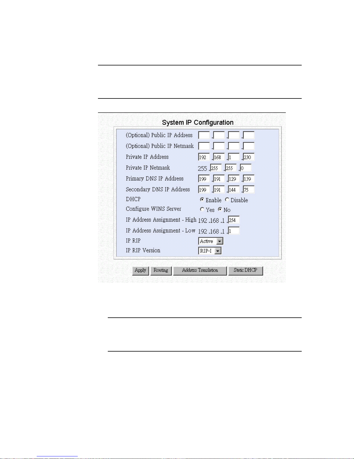
To Configure Advanced IP Settings
Step 1 Select IP from the Menu:
Note: This option is not available if you selected “Basic Internet Access” only
from the ARM Customization screen. Unless you have working experience with
networking and protocols, we recommend that you do not change any of the default
settings.
Configuration - Features - IP
Step 2 Enter the following information:
Note: To install public servers on your network (e.g., Web or ftp servers), you
need to apply for an IP address for each server plus one for the LAN port of the
Broadband Router. All these public IP addresses have to belong to the same IP
network.
Public IP Address: the public IP address for the LAN interface on the
Broadband Router.
Page 46
4-19
Public IP Netmask: the network mask for the public network address on
your LAN.
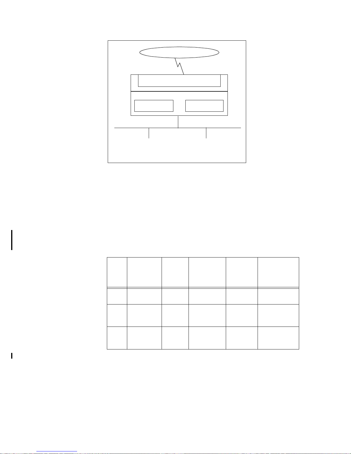
Private IP Address:
the private IP address for the LAN interface on the Broadband Router.
The default private IP address is 192.168.168.230. If you want to create
your own private network through other Broadband Router with remote
offices, you need to make sure that each Broadband Router router on each
LAN is assigned a unique private IP network address.
The default IP private address is 192.168.168.230 with a network mask of
255.255.255.0. This private address may be changed to any private
address and network mask as specified in the following table:
However, please note that once you change the private IP address (such as
from the default of 192.168.168.230 to 192.168.167.230) either from the
browser or through a telnet session (which is based on the IP address), the
device from which you operate will no longer be able to communicate
with your Broadband Router router. To reconnect, you need to restart your
device. This is so that your device will re-acquire the IP address from the
Network
Address
Network
Prefix
Default
Network
Mask
Maximum
Number of
Host
Addresses
Lowest/
Highest
Address
A 10.0.0.0 8 bits 255.0.0.0 16,777,214 10.0.0.1/
10.255.255.254
B 172.xx.0.0 12 bits 255.255.0.0 65534 172.xx.0.1/
172.xx.255.254
C 192.168.xx.0 16 bits 255.255.255.0 254 192.168.xx.1/
192.168.xx.254
Table 4-1 IP Address Ranges for the Broadband Router
LAN Interface
Public IP address
Private IP address
Private
workstations on
Public computers
on your public
network
EWAN Interface
(IP address usually assigned by ISP)
Internet
your private
network
Page 47

4-20
Broadband Router router based on the new private IP address, and then
your device can again communicate with your Broadband Router. For the
same reason, all devices on the LAN need to be restarted before they can
access the Internet again.
Private IP Netmask: the network mask for your private network. Its
value is 255.255.255.0, and cannot be changed.
Primary DNS IP Address:
the IP address of the primary Domain Name Server (DNS). If properly
configured, when a device reboots and acquires the IP address from the
Broadband Router, the IP addresses of both the primary and the secondary
DNS server will be provided to requesting client workstations. When a
Broadband Router connects to the ISP, it will automatically be assigned
the IP address for a primary Domain Name Server (DNS), as well as the IP
address for a secondary DNS. Alternatively, the user can decide that they
want to assign their own DNS IP addresses.
Secondary DNS IP Address: the IP address of the secondary domain
name server.
DHCP: this enables or disables the Broadband Router Dynamic Host
Configuration Protocol (DHCP) feature. If you want the Broadband
Router to act as a DHCP server and assign private IP addresses to
requesting DHCP clients, make sure DHCP is enabled. When enabled, the
Broadband Router will provide an IP address, network mask, gateway
address (the Broadband Router private IP address), DNS addresses and
WINS addresses and node type to any workstation on the local area
network that is configured as a DHCP client.
Devices on your network that are configured with public IP addresses are
not DHCP clients. Therefore, you need to assign their IP addresses,
network mask, default gateway’s IP address, primary and secondary DNS
IP addresses manually.
IP Address Assignment: sets the range of IP address
IP RIP: sets IP RIP to Disable, Active or Passive. The Broadband Router
can both receive routing table broadcasts and transmit routing table
information. When disabled, no routing information is transmitted or
processed if received. When Active, the Broadband Router broadcasts its
address every 30 seconds and also listens for routing information on the
network. When Passive, the Broadband Router does not broadcast its
routing information, but simply listens for routing information from the
network and updates its routing tables.
IP RIP Version: select the system-wide setting of the RIP version to be
used if RIP is enabled. RIP, version 1 (RIP-I) or version 2 (RIP-II) may be
selected. If RIP-II is selected, individual connection profiles may use
either RIP-I or RIP-II. If RIP-I is selected, only RIP-I is used, regardless
of the setting in the individual connection profiles.
Step 3 Press APPLY to save the changes to the Broadband Router, or press IP
Routing Table to display or modify the IP Routing Table (The operation
for Address Translation and static DHCP are described in previous
sections.)
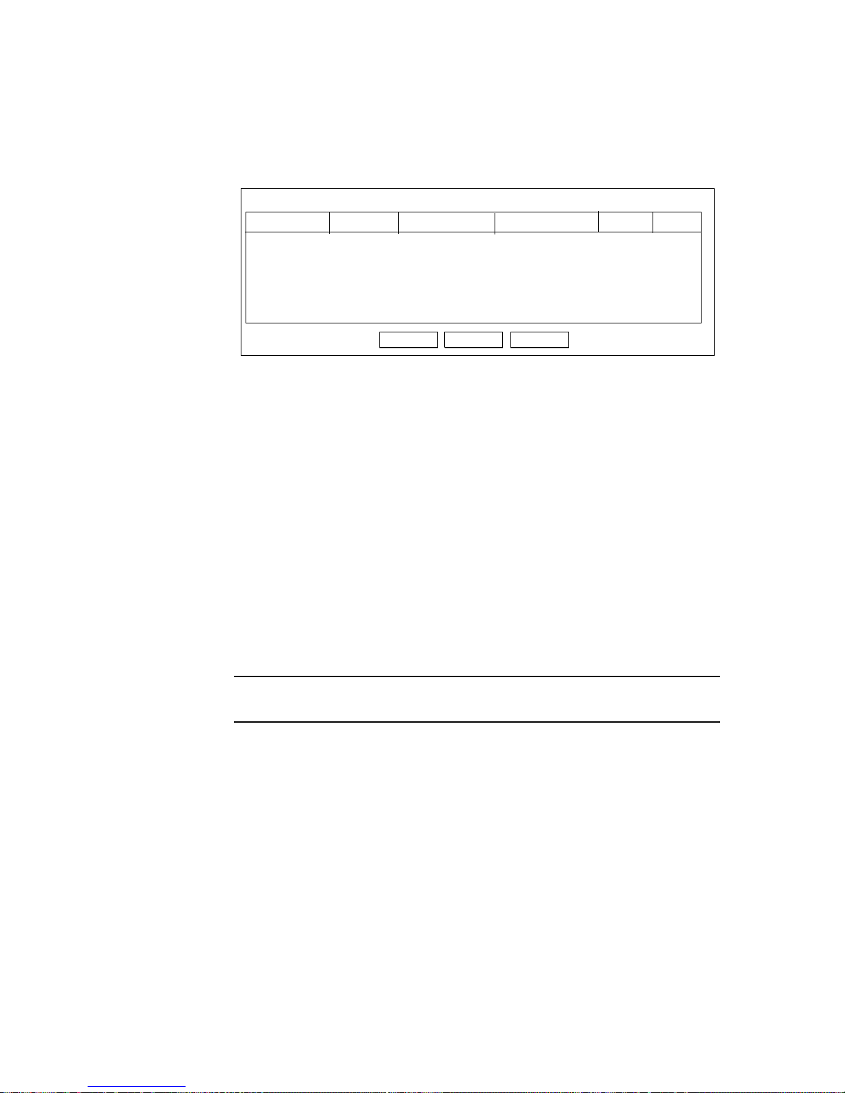
The IP Routing Table
The IP routing table contains all the information that the Broadband Router needs to
Page 48
4-21
route an IP data packet. You can view the IP routing table by clicking on the IP
Routing Table button at the bottom of the System IP Configuration screen. From this
screen, you can also add new routing entries to the table. The following screen shows
an example of the IP routing table.
When an IP packet arrives in the Broadband Router, IP tries to determine if the
destination IP address contained in the packet is within the network defined by the
“Dest IP” and “Netmask” pair of an entry in the routing table. If a match is found, the
packet is forwarded to the interface or profile specified in the “Ifname” field.
The “Hops” field is the number of routers the packet must travel through in order to
reach its final destination. If this value is zero, the destination is in a network directly
attached to this router, such as a LAN.
If no match is found with a destination network, then a special entry called the
“Default IP Route” may be used. This normally is set to a path where another router
can be reached that has additional information about other networks not known to the
local router, such as the interface to the Internet. If no match is found and a default IP
route is not defined, the IP packet is discarded and will go nowhere.
An entry for a specific host or network may be added manually. This “static route” is
indicated by an “S” in the Flags field. Other flag field entries are “H” for host, and
“G” for gateway.
Note: To delete a static route, select it in the routing table and click the Delete
button. You cannot delete Host or Gateway routes.
Adding the Default Route or a Static Route
To add/change the default route or add a static route:
Step 1 Click the ADD button in the IP Routing Table screen to display the
Add
IP Routing Table
NetmaskDest IP Gateway IP IfName Hops Flag
192.168.168.230 255.255.255.0 LAN 0S
Delete Refresh
Page 49
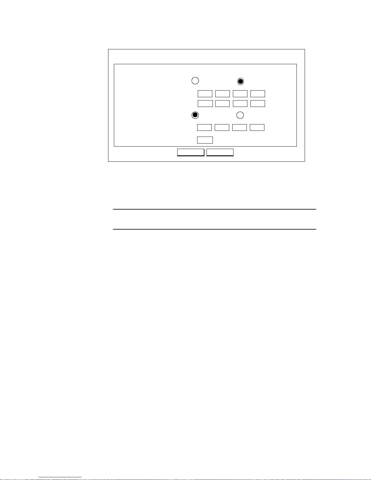
4-22
following screen:
Step 2 Enter the following information:
Add Default Route: select if you want to specify a new default route.
Note that the Remote IP Address and Remote IP netmask fields do not
appear if you select this option.
Note: Mis-configuring the default route may result in abnormal system
behavior and/or unnecessary telephone charges.
Add Static Route: select if you want to add a static route.
Remote IP Address: the remote IP address of the new route.
Remote IP Netmask: the IP netmask of the new route.
Gateway: select whether the gateway is an IP address or interface.
Hop Count: the maximum number of hops for this route.
Step 3 Click APPLY.
Static Route
Add IP
Default Route
APPLY
IP Routing Table
Remote IP Address
Remote IP Netmask:
Gateway
Interface
IP Address
. . .
. . .
Hop Count:
CANCEL
1
. . .
Page 50
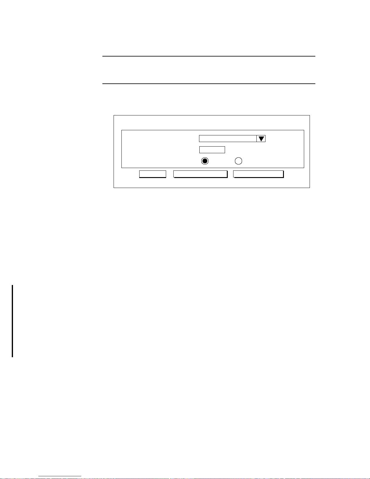
4-23
To Configure IPX Settings
Note: IPX options appear only if you selected Share NetWare (IPX) Resource
on the ARM Customization screen, the IPX feature key have to be installed
previously.
Step 1 To select IPX Protocol, select IPX from the Menu:
Configuration - Advanced Features - IPX:
Step 2 Enter the following information:
Ethernet Frame Type: the Ethernet frame type on the LAN, normally
detected automatically by the Broadband Router, however you may
change this selection. Options are Ethernet_802.3, Ethernet_802.2,
Ethernet_II, and Ethernet_SNAP.
Network Number: a unique identifier for the IPX network on your LAN.
Normally, this is automatically detected by the Broadband Router.
IPX RIP/SAP: enables or disables IPX Routing Information Protocol and
Service Advertising Protocol, used for exchanging routing tables and
server information among IPX RIP/SAP agents.
Step 3 Press APPLY to save the changes to the Broadband Router, or press IPX
Routing Table to display or modify the IP Routing Table or press IPX
SAP Table to display or modify the IPX SAP Table.
The IPX Routing Table
The IPX routing table contains all the information that the Broadband Router needs to
route an IPX data packet. You can view the IPX routing table by clicking on the IPX
Routing Table button at the bottom of the System IPX Configuration screen. From
this screen, you can also add new routing entries to the table. The following screen
System IPX Configuration
IPX Network Number
Ethernet Frame Type
Ethernet_802.2
20000015
IPX RIP/SAP
Enable Disable
APPLY
IPX Routing Table IPX SAP TABLE
Page 51
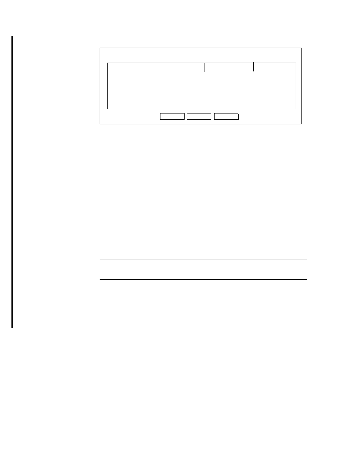
4-24
shows an example of the IPX routing table.
When an IPX packet arrives in the Broadband Router, IPX tries to determine if the
destination IPX Network Number contained in the packet is within the network
defined by the “Network Number” in an entry in the routing table. If a match is found,
the packet is forwarded to the interface or profile specified in the “Gateway IfName”
field.
The “Hops” field is the number of routers the packet must travel through in order to
reach its final destination. If this value is zero, the destination is in a network directly
attached to this router, such as a LAN.
If no match is found with a destination network, then a special entry called the
“Default IPX Route” is used. This normally is set to a path where another router can
be reached that has additional information about other networks not known to the
local router. If no match is found and a default IPX route is not defined, the IPX
packet is discarded and will go nowhere.
An entry for a specific host or network may be added manually. This “static route” is
indicated by an “S” in the Flags field.
Note: To delete a static route, select it in the routing table and click the Delete
button. You cannot delete a non-static route.
Adding the Default IPX Route or a Static IPX Route
The procedure to add or change the IPX default route or to add an IPX static route is
as follows:
Step 1 Click the ADD button at the bottom of the IPX Routing Table screen to
Add
IPX Routing Table
Gateway IfNameNetwork Number Gateway MAC Address
Hops Flags
Default lan 00-40-05-35-DB-4A 0 S
10882244 lan 00-60-20-00-00-15 2
123456ab isdn2 3
Delete Refresh
Page 52
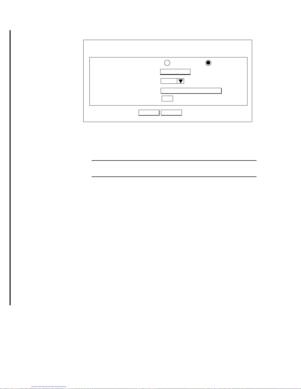
4-25
display the following screen:
Step 2 Enter the following information:
Add IPX: select the type of entry to be added. If you specify a Default
Route, the Destination Network Number and Hop Count fields do not
appear. Select Static Route if you want to add a static route.
Note: Mis-configuring the IPX default route may result in abnormal system
behavior and/or unnecessary telephone charges.
Destination Network Number: the IPX Network Number reachable
through this new route.
Gateway Interface Name: this specifies the interface through which the
destination network can be reached. This is either the LAN or a profile
name.
Gateway MAC Address: identifies the MAC address of the gateway on
the LAN through which the Destination Network Number can be
reached. This field only appears if the Gateway Interface Name is the
LAN.
Hop Count: the maximum number of hops for this route.
Step 3 Click APPLY.
The IPX SAP Table
The IPX SAP table contains Service Advertising information gathered from adjacent
routers or configured statically. This information provides requesting IPX clients with
the services available on their network and a path to reach that service. You can view
the IPX SAP table by clicking on the IPX SAP Table button at the bottom of the
System IPX Configuration screen. From this screen, you can also add new SAP
Apply
IPX Routing Table
Cancel
Static Route
Default Route
Add IPX
lan
Gateway MAC Address
Hop Count:
1
Add a Static IPX Route
1088224
00-60-20-00-00-
Destination Network Number
Gateway Interface Name
Page 53
4-26
entries to the table. The following screen shows an example of the IPX SAP table.
SAP table entries contain the following pieces of information:
- Server Name: This is a string of up to 48 characters that identifies the
device providing the service
- Network Number: This is the identification of the network on which the
Server resides
- Node: The node address of the device providing the service. Note that this
node address may correspond to the device’s physical MAC address, or it
may be an internal node number
- Socket: The two byte (four hexadecimal digit) address of the IPX socket
providing the service
- Type: The Service Type. Well-known service types include:
- IfName: The name of the interface through which this resource may be
accessed. This is either the LAN or a connection profile name
- Hops: The number of routers the packet must travel through in order to
reach its final destination. If this value is zero, the destination is in a network
directly attached to this router, i.e., the LAN.
- Flags: An “S” denotes a static IPX route
The Broadband Router will respond to a workstation request for the names and
address information of servers of a specific service types or all service types. The
router will search the SAP table for these entries and respond with the necessary
information that the workstation can use to communicate with the desired service.
An entry for a specific service may be added manually. This “static SAP entry” is
indicated by an “S” in the Flags field.
Service Type
Hexadecimal
Value
Unknown 0000
Print Queue 0003
File Server 0004
Job Server 0005
Print Server 0007
Archive Server 0009
Remote Bridge Server 0024
Advertising Print Server 0047
Add
IPX SAP Table
Network
Server Name Socket
IfName
Flags
NTSERVER 10882244 00400535DB4A E885 640 lan
1
NWSERVER 2FA694BB 000000000001 0451 4 lan
3
Delete
Node
Type Hops
Refresh
Page 54
4-27
Note: To delete a static SAP entry, select it in the SAP table and click the Delete
button. You cannot delete non-static entries.
Adding a Static SAP Entry
The procedure to add an IPX static SAP entry is as follows:
Step 1 Click the ADD button at the bottom of the IPX SAP Table screen to
display the following screen:
Step 2 Enter the following information:
Server Name: The name of the server offering the service. This name
may be up to 48 characters.
IPX Network Number: The network number on which the server resides.
Up to eight hexadecimal digits may be entered.
IPX Node Number: The node number of the server. This is entered as six
pairs of hexadecimal digits.
IPX Socket Number: The socket number used to reach this service (up to
four hexadecimal digits).
IPX Service Type: The type of service offered. See the table above for
typical Service Types. Up to four hexadecimal digits are accepted. The
value “FFFF” is not valid.
Hop Count: the number of hops to reach this device.
Flags: An “S” denotes a static IPX SAP entry.
Step 3 Click APPLY.
Apply
IPX SAP Table
IPX Network Number
Cancel
Server Name
IPX Node Number
IPX Socket Number
IPX Service Type
Hop Count:
1
Add an IPX SAP Table Entry
00-00-00-00-00-00
Page 55
4-28
To Enable Bridging Learning
Note: To configure Bridge function, you must have the Bridge feature key
installed.
Step 1 To enable the bridging learning protocol, select Bridging from the Menu:
Configuration - Features - Bridging:
Step 2 Enter the following information:
Learn MAC address: enables or disables Learning. If Learning is
enabled, the Broadband Router maintains a MAC address table that keeps
track of the relationship between MAC addresses and network interfaces so that the system knows which device is reachable through which
network interface.
Note: Enabling the learning protocol does not enable bridging on any
connection on the Broadband Router. You must enable bridging in the
Connection Profile for a specific WAN connection.
Step 3 Click APPLY.
APPLY
System Bridging Configuration
Learn MAC address
Enable Disable
Page 56

5-1
5
5 Managing the Broadband Router
This Chapter contains the following sections which cover management of the
Broadband Router:
• How to view the connection log
• How to upgrade my Broadband Router features/software
• How to save or clear my configuration changes
• How to reset my system
• How to change the ARM password
• What if I forget the ARM password?
• How to customize my ARM interface
• How to configure general system settings
How to View the Connection Log
The Broadband Router provides a connection log that you can use to track the
connections in establlished both out of or into your Broadband Router. Connect and
disconnect messages can be useful in determining connection costs, Trigger messages
are useful in determining the particular device and application that triggered the
connection.
To view the Connection Log, select Connection Log from the menu:
Monitoring - Connection Log
The Connection Log displays in the Main window:
There are several types of messages that appear in the Connection Log:
Connected and Disconnected messages: Shows the date, time, port (channel) and
profile when a connection is established or disconnected.
Trigger messages: Shows the date, time and details of an event that triggers a
connection.
VPN messages: Shows the detail of Virtual Private Networking sessions.
CONNECTION LOG
DATE TIME
CHANNEL
EVENT
DURATION
DETAIL
Dec-16-99 15:09:45 Modem(profile1) Connected
Incoming Call [33.600 kbps]
Dec-17-99 15:11:25 Modem(profile2)
Disconnected
00:01:40
Page 57
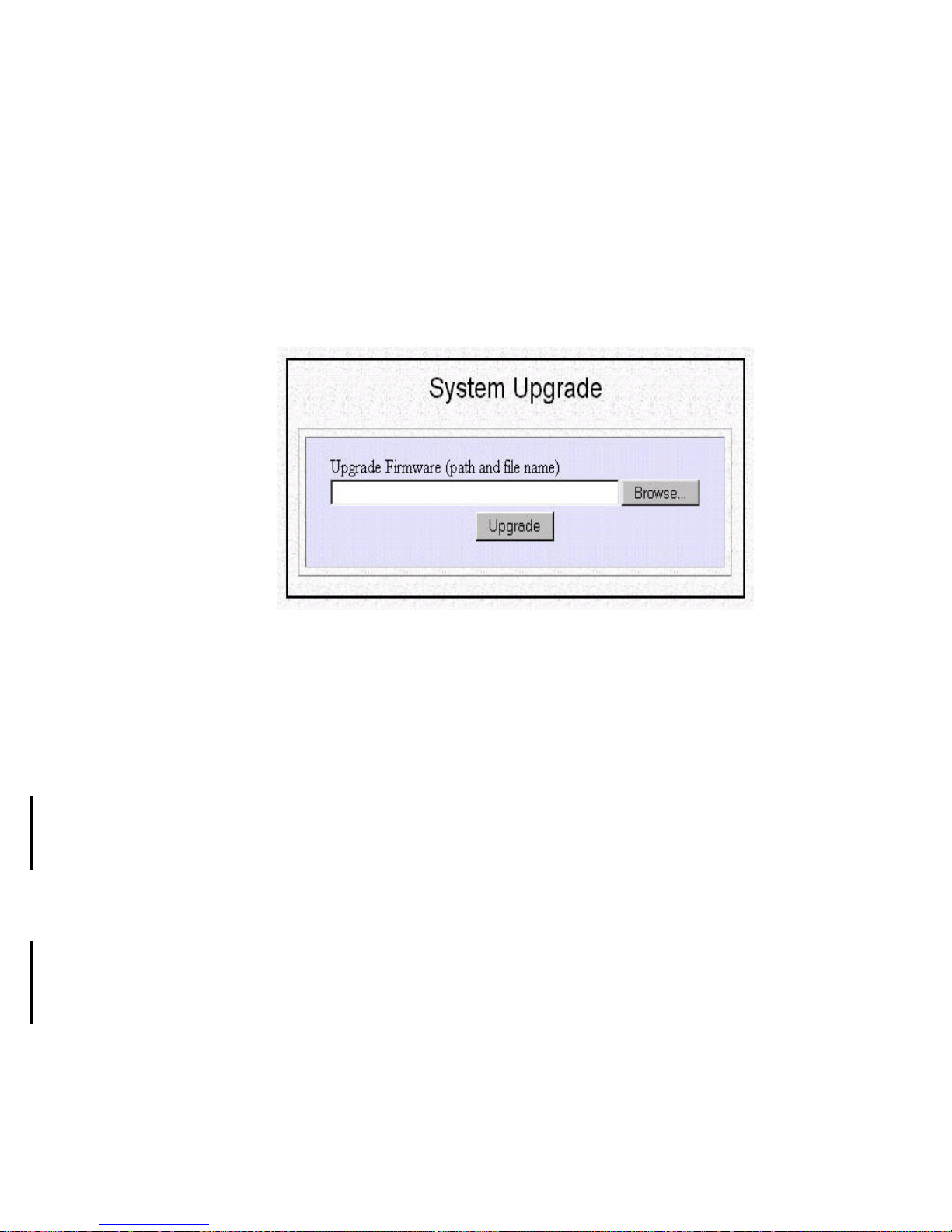
5-2
How to Upgrade the Broadband Router Features/
Software
You can upgrade your firmware (the software that controls the router’s operations).
Normally, this is done when you discover a problem which is resolved in a different
version of firmware that contains new features that you need. Both types of system
upgrade can be performed through the ARM System Upgrade option as follows:
Step 1 Select System Upgrade from the menu:
System Tools - System Upgrade
The following screen is displayed:
Step 2 To update the Broadband Router software, download the software from
distributor’s web site and install the software in your local environment
first, then from the above screen enter a path or filename (e.g.,
a:\P17v500.sig), or click Browse to select a path to the software. Next,
Click the Upgrade button.
The new firmware will begin loading across the network. After a message
appears telling you that the operation is complete, be sure to reset the
system to have the new firmware take effect.
Step 3 Upgrade Feature Key (an alphanumeric number) supplied by your
distributor in the feature key field on the same screen. Then you will see
these features as selectable options when you press Customize User
Interface from the ARM menu.
How to Save or Clear Configuration Changes
Every 30 minutes, the Broadband Router looks for configuration changes that have
been made and save them into the router’s permanent memory.
You can use the Configuration Data Options features to manually save changes or
clear the configuration (i.e., to restore to its factor default configuration).
Step 1 Select Configuration Data Options from the menu:
System Tools - Configuration Data Options
Page 58
5-3
The following screen displays:
Step 2 Select Save to save the current configuration, or Clear and Reset to erase
your entire configuration database and reset the system.
Step 3 When you click Clear and Reset, you will be asked to confirm your
choice.
Click Yes to clear the configuration and reset the system, otherwise click
No to cancel.
How to Reset the Broadband Router
You can reset the system from ARM
Step 1 Select Reset System from the menu:
System Tools - Reset System
The following screen displays:
Step 2 Click YES to reset the Broadband Router. If you do not want to reset the
system, Click No.
Note: Resetting the Broadband Router disconnects any active calls, and
therefore may disrupt current data traffic. Unless you manually save the
configuration, you may also lose most-recent configuration changes (that have
been made within the last 30 minutes after the last auto-configuration save). All
saved configuration changes are restored after the system re-initializes.
Configuration Data Options
Save the configuration to flash memory
Clear the configuration and reset the system
Save
Clear and Reset
Configuration Options
Do you want to continue?
Yes No
Reset System
Do you really want to reset the system?
Yes
No
Page 59
5-4
How to Change the ARM Password
After you start using the Broadband Router, you should change the factory default
ARM password as follows:
Step 1 Select Change Password from the menu:
System Tools - Change Password
The following screen displays:
Step 2 Enter the following information:
Current Password: the current password for the Broadband Router.
New Password: the new password for the Broadband Router
Confirm Password: the new password for the Broadband Router, entered
again for confirmation.
Note: If you are changing the password for the first time, the Current
Password is “password”.
Step 3 Click Submit.
What if I Forget the Password?
If you forget the ARM password, the only way to recover is to clear the entire
configuration and return the unit to its original state as shipped from the factory.
Unfortunately, this means that you have to re-enter all of your configuration data.
To clear the configuration and restore the password to the default, follow these steps:
Step 1 Using the supplied Null Modem Cable, connect a console (or a PC
running a terminal emulation program such as HyperTerminal) to the
Broadband Router Console port. The default port settings are 19200, 8,
None, 1, None.
Step 2 Turn off the Broadband Router, then turn it on again. In the console
window, you’ll see the message “Loading firmware...”.
Step 3 When you see the message "Ready", immediately (within one second)
press Control-C.
Step 4 The Broadband Router resets. When this is complete, the Broadband
Router will return all settings to the factory default. The password will
once again be “password”.
Current Password
New Password
Confirm Password
Password Configuration
SUBMIT
(Forget your password? - see the User’s Guide for instructions.)
Page 60
5-5
Note: Keep in mind that anyone can perform this procedure and seriously
compromise security in your network. Make sure physical access to the
Broadband Router is consistent with your security requirements.
How to Customize the ARM Interface
You can use the ARM Customization feature to specify applications you intend the
router for. Your ARM interface will be customized accordingly to fit your specific
needs.
The ARM Customization screen is the first screen you will see when you are
connected to the ARM for the first time. Afterwards, You need to explicitly invoke
this screen to change your Customization options by selecting Customize User
Interface from the ARM menu.
System Tools - Customize User Interface
When you select/de-select a feature from the list, the corresponding menu buttons and
configuration screens will appear/disappear from your ARM accordingly. This means
when you are not using a feature, the corresponding configuration screen will
automatically disapper.m, and if you are using your Broadband Router for very
simple applications, the ARM will also become a very simple interface to use.
Note: The choices displayed in this screen depend on the feature keys which are
installed in your system.
How to Configure General System Settings
To view or change general system settings, select System from the menu:
Configuration - Advanced - System
A
ccess Router Manager
Basic Internet Access
Internet Access with Advanced Configuration
Share NetWare(IPX) Resource
Select one or more items to be configured during this management session
Next
Page 61
5-6
The following screen displays:
Step 1 Enter the following information:
System Uptime: the elapsed time since the Broadband Router was
powered on(display only).
System Name: a unique name that you assign to this Broadband Router.
System Contact: the network administrator responsible for maintaining
the network.
System Location: where the Broadband Router is physically located.
Step 2 Click APPLY.
System Uptime
System Name
System Contact
System Information
0 months 15 days 03:31:11
System Location
APPLY
James Leigh
Broadband Router
Sunnyvale office
Page 62

6-1
6
6 Messages
This chapter lists messages you may see in the 904S ARM message window.
System Messages
****** has to be an integer [0123456789]
The entered field (******) is not a valid integer.
****** has to be valid IP address
The entered field (******) is an invalid IP address format or an invalid IP address
value.
A
"Account name and/or password not accepted"
User name or password failed authentication by the ISP or the remote site.
"Address already in use"
A duplicate Static Route has been found in the IP Routing Table.
"Advanced Configuration not applied. Duplicate remote IP
address entered"
The IP address entered in the "Optional Remote IP Address" field is either invalid or a
duplicate of an existing entry in the IP Routing Table.
"Advanced Configuration not applied. Duplicate remote IPX
network number entered"
The IPX network number entered in the "Optional Remote IPX Network Number"
field is either invalid or a duplicate of an existing entry in the IPX Routing Table.
"Advanced Configuration not applied. Invalid Remote IP
Address"
The IP address entered in the "Remote IP Address" field is invalid.
"Advanced Configuration not applied. Invalid Remote IPX
Network Number"
The IP network number entered in the "IPX Network number" field is invalid.
"An IPX Network Number is an 8 digits hexadecimal number"
Page 63

6-2
A valid IPX network number may only contain hexadecimal numbers, (0-9, a-f) and
may be up to 8 characters in length.
B
"Browser failed to send out user’s command. Please try again."
A temporary error has occurred while trying to communicate with the router. Please
repeat the operation.
"Browser’s connection has been lost. You can reconnect system
by opening ’http://***.***.***.***’ "
You must re-enter the indicated IP address in order to re-establish a management
session with the router.
"Browser’s passing command failed. Please try again"
A transient error occurred during the communication between the browser PC and the
router. Re-try the operation.
C
"Connection attempt failed. Acquired IP address conflicts with
the router configuration"
The IP address obtained from the EWAN Internet connection was in conflict with an
IP address subnet already defined for an interface of the router. Either change the IP
address subnet for the interface, or contact your ISP for a different address
assignment
"Call operation in progress. Request ignored"
An "Apply and Test" or "Connect" is pressed when a call is already connected.
"Cannot perform operation. Port or profile is currently disabled"
An outgoing call was attempted on a port or profile that has been disabled.
"Cannot disconnect LAN"
This message is displayed when "Disconnect" button is pressed for the LAN
interface.
"Cannot disconnect this type of connection."
An attempt has been made to disconnect a non-switched connection. This type of
profile connection cannot be disconnected.
"Clearing system configuration and restarting, please wait..."
This message is displayed when the router is in the process of clearing all system
configuration and then resetting.
Page 64

6-3
"The confirmed encryption key doesn't match"
The encryption key entered in the "Confirm Encryption Key" field is not the same as
the key in "Encryption key" field.
"Invalid DHCP static IP address"
An Invalid static DHCP IP address has been detected. This is not permitted. Please
select another address or modify the original entry.
"Conflict with dial-in address"
An IP address has been entered which is in conflict with the pool of IP addresses
reserved for dial in users. You must select another IP address, or modify the dial in
address range (from the IP browser screen, or from the Command Line Interface
using the “set user” command).
"Invalid private IP address"
The specified IP address is an invalid private IP address.
"Connection profile limit reached"
The maximum number of profiles that can be defined in the system is 20 Remote
Offices and Internet Access profiles or up to 48 Single User Dial-In profiles. To add
another of either type, you must delete an existing profile from the same type.
"Conversion integer/character failure."
An internal error occurred. Please report this to customer support.
"Current password is wrong. The correct password is required"
The password entered is incorrect. Please re-enter the password.
D
"Destination not currently reachable or call back configured"
Either the phone line is not operational, the destination is busy or doesn’t answer , or
the remote profile is configured for call back and has disconnected the call.
"Detecting IPX network number..."
The system is attempting to automatically detect the IPX network number. This
occurs when a zero or a blank is entered as the IPX network number.
"DHCP static assignment table is full, no more actions allowed"
The maximum number of static DHCP entries has configured. You must delete a
static entry before a new one can be added.
"Disconnecting... Please wait. This action may take some
minutes."
This message is displayed whenever the link is in the process of disconnecting. This
Page 65

6-4
operation may take up to several minutes, depending upon the modem responses.
"Download firmware, please wait (2 minutes)..."
System is downloading new firmware. It takes about two minutes to complete the
operation.
"Duplicate public port"
The specified public port is already used in a static NAT Table entry
"Duplicate static assignment"
The specified Name, MAC address or IP address already exists in the static DHCP
assignment table.
"Duplicate Public Port"
The public port number entered in the “IP Address Translation Configuration” screen
has been configured in another entry. The port number must be unique.
E
"Encryption key is invalid. Please re-enter"
A valid encryption key may only contain hexadecimal numbers, (0-9, a-f) and may be
up to 16 digits in length, depending upon the strength of encryption licensed for the
router site.
"File Invalid"
The firmware file entered is either missing or invalid.
"External logon attempt rejected"
Another browser elsewhere in the network has attempted to open the router’s HTTP
page. This attempt was rejected. Only one HTTTP configuration session allowed at a
given time.
F
"Failed to disconnect. Link is unconfigured"
An attempt was made to "Disconnect" an unconfigured interface.
"Failed to add DHCP static lease entry"
The system could not add a new DHCP entry. Please try again.
"Failed to clear statistics"
The clear statistics operation could not be completed. Please try again.
"Failed to configure IP routing table"
Page 66

6-5
An invalid IP route has entered. Please check the parameters entered and try again.
"Failed to configure system IPX. Please check input and try
again"
The IPX Network Number entered is not valid. IPX Network Numbers consist of
eight hexadecimal digits (0-9, a-f).
"Failed to remove DHCP lease entry"
The system could not successfully delete a DHCP entry. Please try again.
"Feature key is invalid re-enter or contact vendor"
The feature key entered is not valid, or all system features have been enabled.
"Duplicate IP Filter Name. Please use another name"
A duplicate filter name has been detected. A filter name must be unique.
G
"General read failure"
An error has occurred while communicating with the router. Please use the “Reload”
or “Refresh” button to load this page again.
H
I
"The Internet access time has been configured successfully"
This message is displayed when the Internet access time configuration is accepted by
the router.
"Interface is not available"
An invalid interface type was specified during an IP filter configuration.
"Invalid access type selected. Please select again"
You must select one profile type from the list to configure.
"Invalid address range"
The configured IP address range is not valid. Ex: The range should include at least
two private IP addresses between 192.168.xxx.231 and 192.168.xxx.254.
"Invalid DHCP static IP address"
The configured IP address either conflicts with an IP address of an existing entry or is
not in the valid IP address range.
"Invalid entry index"
Page 67

6-6
Current DHCP entry can’t be accessed.
"Invalid Filter IP Address"
This message is displayed when an IP address with a syntax error is entered. An IP
address should be a set of four three-digit numbers. Each three-digit number should
be between 0 and 255, inclusive. For example, a correct IP address is 192.168.100.2.
"Invalid Entry: Private Port"
The private port number entered is not valid. It must be a number in the range of 1 to
65535. Or, the user has entered a port number that is reserved or outside of the legal
range for TCP/UDP ports.
"Invalid Entry: Public Port"
The public port number entered is not valid. It must be a number in the range of 1 to
65535. Or, the user has entered a port number that is reserved or outside of the legal
range for TCP/UDP ports.
"Invalid Filter IP Address"
This message is displayed when an IP address with a syntax error is entered. An IP
address should be a set of four three-digit numbers. Each three-digit number should
be between 0 and 255, inclusive. For example, a correct IP address is 192.168.100.2.
"Filter name is a string up to 30 characters"
The Filter Name entered is not valid. A Filter Name should be between one and 30
characters(numbers, letters, dashes or underscores).
"Invalid gateway configuration"
An invalid value has been entered in the "Gateway" field while attempting to add a
static IP or IPX route.
"Invalid IP address"
The IP address entered is not valid.
"Invalid MAC address"
The format of MAC address entered in the DHCP Static Assignment Table is not
correct. It should consist of 6 pairs of hexadecimal digits (0-9, and a-f) separated by
dashes, as xx-xx-xx-xx-xx-xx.
"Invalid profile name, please use another"
The selected profile name is reserved by the system. Please use another name.
"Invalid remote IP address"
The remote IP address entered in the VPN tunnel configuration is not valid.
"Invalid static DHCP IP address"
Page 68

6-7
The IP address entered in the static DHCP configuration form is invalid. Please check
all parameters entered.
"Remote Tunnel Name is required"
Each tunnel configuration requires a remote system name for authentication. If such a
name is not provided or is invalid, this message will be displayed.
"IP Address is invalid"
The IP address entered as the public or private address was not valid.
J
K
L
"Link is Disconnected"
This message is displayed after the modem link disconnection operation is completed.
"Link is already disconnected"
This message is displayed when an attempt is made to disconnect an inactive modem
port.
"Lower bound address is out of range (231-254)"
The IP address entered in "Dial In IP Address-Low", is not valid. It must be a number
in the range from 231 to 254, and at least one lower than the upper bound IP address
configured.
M
"My Tunnel Name is required"
The Local Name of a tunnel is required.
"Maximum number of tunnels reached. No more are added"
The maximum number of tunnels has been reached. To configure another, an existing
tunnel must be deleted.
"MAC Address not specified"
The MAC address in the static DHCP entry configuration must be 12 hexadecimal
digits (0-9, a-f).
"Management session time out"
The message is displayed when HTTP management session is idle for more than the
idle time out value(default is 10 minutes).
Page 69

6-8
"The menu option you clicked on can’t be found. Please try
again."
An internal error has occurred. Please try this operation again.
N
"NAT translation failed. Procotol not supported."
A Network Address Translation operation failed because the packet protocol type was
unknown or is not supported.
"NAT translation failed. NAT table entry not found for an outgoing
ICMP error message."
An attempt to perform a Network Address Translation operation on an ICMP packet
(e.g., "ping") has failed. The Network Address Translation Table entry could not be
found.
"NAT fails to get proxy entry. Null proxy structure"
An internal error occurred. Please contact customer support.
“The new password does not match the confirmed password”
The re-entered password is not the same as the previous password entered during the
change password operation.
“The new password is the same as the old password”
The new password is the same as the old password.
"Not a static route"
The message is displayed when attempt to delete a non-static route in the IP Routing
Table is made. Only Static Routes may be deleted.
O
"Only one EWAN profile is supported"
The adminstrator is attempting to add a second profile over the EWAN port
"Only 8 rules allowed"
The maximum number of Filtering rules, system-wide, has been exceeded. To add an
additional rule, one must be deleted.
P
Parameter changes applied
Changed parameters have been applied to the router configuration.
Page 70

6-9
"Passwords are 6 - 15 characters (numbers, letters, dashes,
underscores, dashes or colons) starting with a letter or a
number"
The password entered is invalid. A passwords must be more than 6 characters and less
than 15 characters. They can be digits, letters, dashes, underscores, dashes or colons,
and must begin with a letter or a digits.
"The password has been changed"
The new password is configured. Your new password will take effect the next time
you logon.
"Phone number or data service type seems to be incorrect"
After an "Apply and Test" button is pressed, the router detected a problem with either
the remote phone number or the data service type configured.
"Phone number up to 15, limit characters to 123456789,;-[]!*#"
The phone number field has been configured incorrectly. Up to 15 characters may be
entered. Only the numbers from 0 to 9, and the characters ",", ";","-","[", "]",, "*",
"#"and "!" may be entered.
"Placing VPN call. Please wait..."
The router is in the process of establishing a Virtual Private Networking session.
"Please add a filter to this interface first before setting ’sent’ or
’discarded’"
A Filtering Rule must be configured before the Default Rule (’Forward’ or ’Discard’)
can be set.
"Please select an access type"
The type of Connection Profile to be configured must be selected from the Access
Type list.
"The Port number should be 1 ~ 65535"
The port number entered in a filter rule should be in the range of 1 to 65535.
"The profile name is used by another profile"
A duplicate profile name is entered. Profile names must be unique.
"Primary WINS server IP Address is required"
If the user has selected “Yes” for “Configure WINS server”, then at least a primary
WINS server IP address must be entered. Otherwise, change the “Configure WINS
server” choice to “No”.
"The Public Port Number Has Been Reserved By System"
The port number entered is reserved and may not be mapped. The following port
Page 71

6-10
numbers have been reserved by the system: 9800, 9801, 9802, 17783, and 17784.
Q
R
"Remote call back phone number unspecified"
“Call Back” is selected but a “Call Back Phone Number” is not provided.
"Remote name unspecified"
Please enter a Remote Name. This is a required parameter in a VPN tunnel
configuration.
"Remote phone number is unspecified"
A Remote Phone Number is required.
"Remote phone number is unspecified"
This message is displayed when the required remote phone number has not been
entered.
"The remote account name already exists. Please change to
another user name"
A duplicate user name is entered. Dial-In user names must be unique.
"Resetting system, please wait..."
The message is displayed when the router is in the process of resetting. You can logon
to the router after about 30 seconds.
S
"Save configuration failed. Please try again"
The system failed to save the configuration. Please try again.
"Save configuration succeeded"
The configuration was saved to flash memory successfully.
"Searched entry exists"
The IP route being added already exists.
"Search failed"
An internal error has occurred.
"The specified tunnel is incoming only"
Page 72

6-11
A tunnel profile defined as "Incoming Only" cannot be used in an outgoing VPN
profile.
"Static entry not found"
An attempt was made to locate an entry which does not exist.
"Statistics Cleared"
The Broadband Router has completed a clear statistics operation on the link selected
in the System Status Monitoring Window.
"Static DHCP Entry Not Found"
A DHCP entry must be selected to “Edit” or “Delete”.
"Static routes to single user profiles not allowed"
You have entered an illegal configuration. Static routes can only be configured over
Internet Access or Remote Office Access profiles. You cannot configure a static route
to a Single User Dial-in profile.
"System received incompleted user's command. Please try
again"
An internal error has occurred. Please retry the operation.
T
"The system is disconnecting"
A "disconnect" button is pressed, while the system is in the process of disconnecting
an active modem link.
"The system time has been configured successfully"
The time has been configured successfully.
"The Gateway IP Address has been set as the IP Default Route"
The Internet access profile has been configured in the router and the configured ISP
Gateway IP Addrress is now set as the IP Default Route
"This interface has been configured to support a Remote Office
profile. You must use the Command Line Interface for this type of
configuration"
An EWAN profile has been configured to support Office-to-Office communication.
This type of profiles can only be configured using the Command Line Interface.
“This operation will cause a system reset upon completion. All
unsaved configuration changes will be lost. ”
A "Download Firmware" operation through a directly connected Command Line
Interface session will cause a system reset after the operation is complete. This
Page 73

6-12
message informs the user that ongoing operations may be interrupted and that any
configuration changes made within the last 30 minutes (the default time period for
automatic configuration saves), may be lost as a result.
"This profile no longer exists"
The profile being configured no longer exists in the system. Please reload or refresh
the browser page and try again.
"Tunnel does not exist"
This message is displayed when an attempt is made to delete a non-existent tunnel.
V
"Value for idle time is invalid - choose between [0, 3600] seconds"
The idle timeout value entered was incorrect. The correct values are 0 (if no idle
timeout is desired) or 1 to 3600 seconds.
W
"Warning! You have changed the default HTTP port used by
remote Internet users of the Web browser configuration tool. In
order to access this tool remotely through the Internet, you must
re-assign the router's HTTP port (e.g., to 8080). LAN users may
continue to access the Web browser configuration tool as usual."
The administrator has assigned port 80 to another LAN device. Since this is the
default HTTP port for remote Internet users, this message appears to remind users
that the Web browser configuration tool is no longer accessible until HTTP is reassigned to another port. If the user has issued this command from a remote location,
through the Internet, then connectivity is lost immediately. At that point the user can
still use telnet through port 23 to issue a CLI command to do this. If port 23 has been
re-assigned, the administrator must re-assign the HTTP port using the CLI through a
new Telnet router port (if available), from a LAN-attached device, or through a nonInternet connection.
Note: Address Translation only applies to Internet connections
"Warning! You have changed the default TELNET port used by
remote Internet users of the CLI. In order to access the CLI
remotely through the Internet, you must re-assign the router's
Telnet port (e.g., to 8023). LAN users may continue to access the
CLI or the Web browser configuration tool as usual"
The administrator has assigned port 23 to another LAN device. Since this is the
default Telnet port for remote Internet user Command Line Interface configuration,
this message appears to remind users that the Command Line Interface is no longer
accessible over the Internet until Telnet is re-assigned to another port. If the user has
issued this command from a remote location, through the Internet, then connectivity
is lost immediately. At that point the user can still use HTTP through port 80 to access
the Web browser configuration tool to do this. If port 80 has been re-assigned, the
administrator must re-assign the Telnet port from a newly re-assigned router's HTTP
Page 74

6-13
port (if available), from a LAN-attached device, or through a non-Internet connection.
Note: Address Translation only applies to Internet connections
Page 75

A-1
A
A Specifications
Application
• Internet Access via Cable or xDSL
• Accessing Servers from the Public Network
• Supporting Multimedia Applications
• Creating Virtual Private Network
Features
Internet Access, Multimedia Applications and Virtual Server
• Multiple users to share Internet Access
• IP routing and NAT/PAT support
• Supporting PPPoE client function for xDSL connection
• Supporting Mac clone for cable modem connection
• Supporting Multimedia application(ICQ, Netmeeting, CUSeeMe, Quick Time,
etc)
• Supporting Virtual Server
Protocol Support
• PPP
• PPPoE
• IP routing, RIP-1/2
• NAT/PAT
• IPX
• Transparent bridging
• L2TP
Page 76

A-2
Management
• Cisco-like Command Line Interface(CLI)
• Embedded Telnet server for remote Console management
• Customized Web-based GUI
• Firmware upgrade via Web-based GUI/Console port
• Configuration date upload and download via TFTP
• Internet Access time restriction feature
• Support DHCP server/client
• SNMP MIB support, easily for MIS staff
• Multiple connection profile
Monitoring
• Runtime traffic monitoring
• Connection log
Security
• Natural firewall, private IP addresses not accessible from the Internet
• IP Packet filtering (IP address/ Protocol/Port number)
• IPX Packet filtering( Network number/Node number/Socket number)
• PPP PAP/CHAP/MS-CHAP authentication
• DES Encryption with L2TP protocol support
VPN
• L2TP with DES Encryption
Physical Specification
• Electrical Specification
External power adapter with AC 9V/1A input
• Dimensions
H:30mm W:130mm D:175mm
• Weight
310g
• EMI Certification
FCC part 15, CE, VCCI Class B
Hardware Configuration
• LAN: 1-Port 10BaseT/100BaseT Ethernet switch, with Uplink Switch
• EWAN: 1 10BaseT RJ-45 EWAN port for connecting Internet through ADSL/
Cable modem
• Console: 1 DB-9 male port direct connection of management console
• LED: 7 LEDs for Power, WAN: COL, ACT, LAN: 10/100, COL/ACT and
PPPoE
Page 77

A-3
• 1 power jack for AC Adapter 9V/1A
• 1 Power Switch
Page 78

B-1
B
B Glossary
This section provides some common networking terms you may find in this user
guide.
ARP, ARP Table
To send an IP packet to another device on the same LAN, the source device needs to
know the MAC address of the destination device first.
If such information is already maintained in the ARP (Address Resolution Protocol)
table, the corresponding MAC address will be used to transmit the data packet.
Otherwise, the data will be queued up first, and an ARP broadcast packet sent out to
the LAN. The device that has a matching IP address will respond with the IP-to-MAC
mapping information. When the response is received, the data that was previously
queued up will be transmitted, and the mapping information stored into the ARP
cache table for re-use later.
ARP table is a cache table that contains MAC-address-to-IP-address mapping
information.
Bit, Byte
These are units of information as stored in computers. A bit has a binary value of 0
and 1, which is the most basic unit for representing information. A byte consists of 8
bits, and therefore can have a value of between 0 and 255. A byte can represent any
character you can see on a computer keyboard, including upper case and lower case
characters. Therefore a document of a certain number of characters can be represented
in a computer as the same number of bytes plus some additional bytes that represent
other information such as the font of each character and the format of the document.
BootP
The Bootstrap Protocol (BootP) is an older version of the Dynamic Host Control
Protocol (see DHCP).
Bridge
A bridge is an intelligent, internetworking device that forwards or filters packets
between different networks based on data link layer (MAC) address information.
Bridge Address Table
A table containing association information between MAC addresses and interfaces in
a bridge. The bridge learns the association by inspecting each and every packet it sees
from each interface. The table is used to decide whether to filter or forward each
packet it receives from each interface.
Page 79

B-2
Broadcast, Unicast
A data packet contains data, the sender’s address and the receiver’s address - just like
a letter to be mailed.
There is a special type of data packet that is delivered to every destination on the
network. This is called a broadcast packet. When there is only a single receiving
party, it is called a unicast packet.
CHAP
CHAP stands for Challenge Handshake Authentication Protocol. It is an
authentication protocol used in PPP for communication devices to authenticate each
other remotely. The password is first encrypted before it is sent to the remote side.
This is as opposed to the PAP protocol, which sends the password in clear text.
Compression
Since data bandwidth over the WAN is usually quite expensive, data is usually
compressed first before it is sent out over the WAN, and decompressed when data is
received from the WAN.
Different types of compression algorithms are oriented towards different types of
data, but generally, certain data patterns are recognized and are abbreviated before
transmission. At the receiving end, the abbreviation is restored to the full data pattern.
A good compression algorithm can achieve a compression ratio of 4 to 1, depending
on the nature of the data being compressed.
Connection Profile
A connection profile contains all necessary information required to set up a dial-up
connection. For example, an Internet access connection profile contains the ISP’s
phone number, the account name and the account password, among other
information.
CPE
CPE stands for Customer Premises Equipment. It refers to any equipment that resides
on the customer premises.
Default IP Route
The default route is a special IP route in the IP routing table. When a packet is
received by the router, if destination network cannot be found in its routing table, the
packet will be forwarded over the default route to the next-hop IP router. Such a
router often has a more complete routing table, and therefore is “more
knowledgeable” about how to route the packet.
Default Gateway (Router)
Every non-router IP device needs to configure a default gateway’s IP address. When
the device sends out an IP packet, if the destination is not on the same network, the
device has to send the packet to its default gateway, which will then send it out
towards the destination.
Page 80

B-3
DHCP, DHCP Client, DHCP Server
DHCP (the Dynamic Host Control Protocol) is the protocol that a DHCP client uses
to communicate with a DHCP server to ask for an IP address to be assigned. Other
network parameters that can be assigned using the DHCP protocol include network
mask, the primary DNS IP address, the secondary DNS IP address, the default
gateway IP address, WINS Server addresses, NetBIOS Node Type, etc.
Edge Router
A router that resides at the edge of a network. It is like a gateway that is used to
communicate with the outside network.
Encryption
A method for scrambling data which inhibits unauthorized snooping. To ensure
privacy of data sent over the network, the data is often encrypted before it is sent out,
and decrypted when it is received. This is used to protect private data from being
pirated, especially when data is sent over the WAN.
Dial-on-Demand, Bandwidth-on-Demand
If the user uses a switched (dial-up) service to access the Internet, the associated
telecomm cost is often directly proportional to the amount of time the user uses the
network service to connect to the Internet. Therefore often it is designed so that the
connection will be triggered only when there is a need - such as when a user tries to
use a web browser to access the Internet.
For ISDN, when there is a demand, the device will first bring up one B channel to
provide 64Kbps (or 56Kbps) data bandwidth. If traffic is heavy, such as when more
users want to access the Internet, the user can configure the device to bring up the
second B channel to provide higher data bandwidth. Such a capability is called
Bandwidth-on-Demand.
EWAN
The EWAN(Ethernet Wide Area Network) Port is where you will connect your cable
or DSL modem
Flash Memory
This is a special read-write memory in a computer system that allows the computer
program (firmware) or the user configuration data to be stored. Its content will
continue to exist even when the power is turned off.
ICMP
The Internet Control Message Protocol (ICMP) is part of the TCP/IP protocol suite,
which is often used for error reporting and control purposes, including the use of the
diagnostic PING command.
Idle Timeout
The Idle Timeout is an amount of time during which no productive data transfer
Page 81

B-4
occurs. If the user uses a dial-up service to access the Internet, the associated
telecommunication cost is often directly proportional to the amount of time the user
uses the network service to connect to the Internet. Therefore, the Idle Timeout is
designed so that after there is no traffic to the Internet for a pre-configured amount of
time, the connection will automatically be taken down.
IGMP
IP Group Multicast Protocol, a protocol that is used as part of the IP multicast
protocol.
Internet Access and ISP Accounts
To access the Internet, first you need to have a device (such as a router or a modem)
that you can use to connect to the Internet using a dial-up services such as modem or
ISDN or a fixed connection service such as a leased line or a frame relay network.
Then you need to find a local ISP and apply for an ISP account, so that you can get an
account name and the associated password that you need to access the Internet.
Generally speaking, only one device can directly use a modem or an ISDN line to
access the Internet. But if you use a router, you can allow multiple users to share the
router to access the Internet.
IP Address and Network Mask
IP address is a unique identifier for a device in the IP network. It consists of 2
portions: the IP network address, and the host identifier.
The IP address is a 32-bit binary pattern, which can be represented as four cascaded
decimal numbers separated by “.”: aaa.aaa.aaa.aaa, where each “aaa” can be anything
from 000 to 255, or as four cascaded binary numbers separated by “.”:
bbbbbbbb.bbbbbbbb.bbbbbbbb.bbbbbbbb, where each “b” can either be 0 or 1.
A network mask is also a 32-bit binary pattern, and consists of consecutive leading
1’s followed by consecutive trailing 0’s, such as
11111111.11111111.11111111.00000000. Therefore sometimes a network mask can
also be described simply as “x” number of leading 1’s.
When both are represented side by side in their binary forms, all bits in the IP address
that correspond to 1’s in the network mask become part of the IP network address,
and the remaining bits correspond to the host ID. For example, if the IP address for a
device is, in its binary form,
11011001.10110000.10010000.00000111, and if its network mask is,
11111111.11111111.11110000.00000000
It means the device’s network address is
11011001.10110000.10010000.00000000, and its host ID is,
00000000.00000000.00000000.00000111.
IP Packet Filter
A feature that allows selective IP packets to be filtered (thrown away). This feature
means each and every packet to or from an outside network will be inspected to see if
it matches the user defined criteria. When there is a match, the packet will either be
filtered or forwarded depending on the configuration.
Page 82

B-5
This feature can be used to block certain types of data, such as for security reasons, or
when parents want to make sure that their children do not access certain web sites.
IP Multicast
A protocol that allows only one copy of data to be sent out for multiple destinations in
the network. This allows the network bandwidth to be used most effectively for
multimedia applications.
IPX Address
The network layer address for the IPX protocol, which contains a 4-byte network
number (unique for each LAN segment and frame type combination), the 6-byte
MAC address of the device, and the 2-byte socket number that maps to the particular
application in the device.
IPX Network Number
A unique identifier for an IPX network, which is also the beginning 4-bytes of a 12byte IPX address. It is unique for each LAN segment and frame type combination.
IPX RIP
The IPX Routing Information Protocol, which is used for exchanging and
maintaining the IPX routing table with neighboring routers.
IPX SAP
IPX SAP (Service Advertising Protocol) is a protocol used for advertising services
available from IPX devices and for exchanging server tables among IPX SAP devices
(agents). For example, the SAP table is broadcasted either periodically or whenever
there is a change in the SAP table, or when the IPX SAP device receives SAP table
queries from other IPX SAP devices.
LAN & WAN
Local Area Network & Wide Area Network. Common LAN technologies include
Ethernet, Token Ring, Fast Ethernet. WAN technologies include analog modem,
leased lines, ISDN, frame relay, and ATM.
LAN to LAN Communication
When two physically disjoint offices of the same company need to communicate and
share data resources with each other, they can use one router on each side and
perform LAN to LAN communication - to allow users on one LAN to access
resources on the other.
MAC Address
The Media Access Control (MAC) address is a unique identifier for a device with an
Ethernet interface. It is comprised of two parts: 3 bytes of data that corresponds to the
Manufacturer ID (unique for each manufacturer), plus 3 bytes that are often used as
the product serial number.
Page 83

B-6
Multiconnection IP (MIP)
Multiconnection IP is a technology, pioneered and proprietary to Pivotal Networking,
that combines multiple WAN channels at the IP level to provide increased bandwidth
by utilizing both channels for the transmission of data. Since MIP operates at the
Network layer (as opposed to Multilink PPP, which operates at the Data Link Layer),
each MIP connection requires its own IP address. This feature is commonly used to
access the Internet using multiple modem accounts and is completely transparent to
an Internet Service Provider.
Multilink PPP
Multilink PPP is an extension of the PPP protocol for utilizing multiple connections
for one single communication. Each connection can be an async modem connection, a
leased line, or an ISDN B channel connection. Common multilink applications are as
follows: (1) back-up: when the “primary” PPP connection such as a leased line is
down, a secondary back-up ISDN or modem connection will be set up automatically
to take over the communication. For a modem router, such a feature would not apply;
(2) load-sharing over 2 modem connections: to allow data to be communicated over
two modem connections simultaneously in order to achieve higher combined data
throughput; (3) overflow: when the traffic load on a primary modem connection
exceeds a certain predefined high threshold, a secondary modem connection will be
set up automatically, until the traffic load falls below a low threshold. Note that for
the StarGazer 1700, only LAN-to-LAN connections (between two StarGazer 1700s)
support Multilink PPP.
NetBIOS
NetBIOS is an interface used by Microsoft Windows networking applications that
transfers Windows information and data from one Windows machine to other
networked Windows machines.
NetWare
The name of an IPX based Network Operating System developed by Novell. It has
evolved to work with the IP protocol equally well now.
PPPoE
Short for PPP over Ethrenet, relying on two widely accepted standards, Ethernet and
the Point-to-Point Protocol. It is a communications protocol for transmitting
information over Ethrenet between devices from different manufacturers
PAP
PAP stands for Password Authentication Protocol. It is an authentication protocol
used in PPP for communication devices to authenticate each other. The password is in
a clear text form when it is sent to the remote side. This is as opposed to CHAP
protocol, which sends the password in an encrypted form.
Ping
A utility that can be used to send a special packet to a remote device to be echoed
back. This is often used to check if a remote device is reachable or not, and what the
round trip delay is. Some variation of the utility such as trace-route can provide
Page 84

B-7
detailed information all intermediate routers the echo packet has gone through, so that
if the packet does not come back, the break in the path can easily be identified.
PPP
Point-To-Point Protocol, one that is frequently used in modem dial-up or ISDN
connections.
Private Network
When a device uses a technology called PAT (Port Address Translation) to
communicate with the Internet, all devices on the LAN will be assigned private IP
addresses. Although they are free to communicate with the outside world, they are not
reachable from the Internet, making the LAN a private network to the outside world.
Protocol
A protocol is a set of rules for interaction agreed upon between multiple parties so
that when they interface with each other based on such a protocol, the interpretation
of their behavior is well defined and can be made objectively, without confusion or
misunderstanding.
A communication protocol is a set of rules defined for data communication that
potentially define the format and the meaning of messages exchanged between
communicating devices. The idea is to define a standard that every product conforms
to, so that devices from different vendors can communicate with each other without
confusion or misunderstanding. Such a standard definition is important today since
users have learned their lessons over the years not to be locked in to any company's
proprietary way of communicating with each other.
For example, the Point-to-Point Protocol (PPP) is the most popular protocol that is
used when a user connects through an ISP to the Internet using a modem or an ISDN
line. It defines a sequence of message exchanges between the user's device and the
ISP's device for the purpose of authenticating the user (asking for the user account
name and password) and assigning an IP address to the user. Other commonly used
protocols are Ethernet, ATM, TCP/IP, ISDN call set-up/take-down, etc.
Remote Access Server
A remote access server (RAS) allows a remote PC user to dial in through it to the
local LAN environment to share resources on the LAN.
RIP, RIP II, OSPF, Routing Protocol
RIP stands for Routing Information Protocol. It is a routing protocol used by routers
to exchange routing table information with each other. RIP II is a newer version.
OSPF stands for Open Shorted Path First, and is a newer routing protocol. Because of
its ability to exchange routing table information faster in a large network
environment, it is commonly used in a large network (such as the Internet network),
while RIP/RIP II are more popular in corporate or private networks.
Router
An intelligent, internetworking device that will forward or filter packets between
different networks based on data link layer (MAC) address information.
Page 85

B-8
A router is an intelligent, internetwork device that forwards packets between different
networks based on network layer address information. An IP router uses IP addresses,
while an IPX router uses IPX addresses.
When a packet is received, the destination network address contained in the packet is
looked up in the routing table to determine which next-hop router to forward the
packet to. (The next-hop router is in theory one hop closer to the destination.)
Routing Table
A router relies on a routing table to determine where to forward a received packet.
The routing table normally contains, for each destination network, the network
address of the next hop router, the hop count to the destination network, an aging
count, among other information.
The aging count is for information aging purposes: the routing table is periodically
exchanged and kept up-to-date. If a router fails, any network reachable only through
this router will become unreachable. The routing table will reflect such failure either
by (1) a router detecting the failure, and broadcasting the failure to everyone else, or
(2) when the corresponding routing entries in the routing table age out (no update for
a long time).
RSVP
RSVP (ReSerVation Protocol) is a protocol that is used for QOS (Quality Of Service)
negotiation in a network, to reserve resources in order to support multimedia
applications.
Single IP Address, PAT
This is a technology that allows all devices in the local network to share one single IP
address when communicating with the outside world, e.g., the Internet. Internally, it
relies on the PAT (Port Address Translation) technology to perform the sharing
function.
Most routers today acquire this single IP address dynamically from the ISP when a
connection is established.
When properly designed, the router can completely relieve the user the burden to
apply for or configure any IP addresses (plus other network parameters) for the entire
network.
SPX
This is a reliable transport layer protocol used in the IPX environment. While IP is
equivalent to IPX in functions it performs, SPX is equivalent to TCP.
Static Route
A route in the routing table that is manually configured rather then learned through
routing table exchanges.
TCP/IP, UDP
Both TCP (Transmission Control Protocol) and UDP (Unreliable Datagram Protocol)
are transport layer protocol. TCP performs proper error detection and error recovery,
and thus is reliable. UDP on the other hand is not reliable. They both run on top of IP
Page 86

B-9
(Internet Protocol), a network layer protocol.
Un-numbered/numbered Link
When the connection of a router to the WAN (Wide Area Network) is assigned an IP
address, it is called a numbered link. Otherwise, it is called an un-numbered link.
VPN, L2TP, PPP/ECP, DES, IPSec
VPN stands for Virtual Private Network. It is a new technology that allows remote
devices to communicate with each other through the Internet securely - without
having to pay long distance charges.
It consists of two parts: (1) a method to create a tunnel between two communicating
devices, and (2) a method to encrypt/decrypt out-going/in-coming data.
The standard tunneling protocol is L2TP, which stands for Layer 2 Tunnel Protocol.
PPTP, a de facto standard from Microsoft, is being gradually replaced by it.
The standard security protocol is the DES encryption algorithm together the IPSec
control protocol. However, since IPSec is still not finalized, some products use other
standard control protocols such as ECP (Encryption Control Protocol) which is a subprotocol of the standard PPP (Point-to-Point Protocol).
Web-based Graphical User Interface (GUI)
Many devices support a graphical user interface that is based on the web browser.
This means the user can use the familiar Netscape or Microsoft Internet Explorer to
control or monitor the device being managed.
WINS Server
The Windows Internet Naming Service provides a means of Windows name-toaddress resolution in a network which includes Windows machines. The WINS
Server is an NT based application which maintains the WINS database and provides
service to requesting WINS clients.
Page 87

C-1
C
C Warranty, Copyrights, FCC Notice
Warranty
901 series Broadband Router is provided with a limited oneone year Warranty.
Details of the warranty and return process are explained in the Warranty Policy
below. Warranty service is subject to the terms and conditions of company Warranty
Policy.
1. WARRANTY:
901 series Broadband Router (the "Product") carry a one (year1) year limited
warranty, except for the power supply units, which carry a one (1) year limited
warranty (collectively the Warranty).
The Warranty covers:
(1) Defects in materials and workmanship of the Product under normal use and
service (Product Defects).
(2) Failure of the Product to perform in accordance with product specifications
published by company (Product Performance).
This Warranty is in lieu of all other express warranties that might otherwise arise with
respect to the Product. No individual or organization of whatever form, connected to
company or not, has authority to change or add to this Warranty.
This Warranty does not apply to any failure of the Product which results from
accident, abuse, misapplication, alteration, or failure due to attached equipment, and
company assumes no liability as a consequence of such events under the terms of this
Warranty. While company has made every effort to provide clear and accurate
technical information about the application of the Product, company assumes no
liability for any event arising out of the use of this technical information.
INCIDENTAL AND CONSEQUENTIAL DAMAGES CAUSED BY
MALFUNCTION, DESIGN DEFECT, OR OTHERWISE WITH RESPECT TO
BREACH OF THIS WARRANTY, OR ANY OTHER EXPRESS OR IMPLIED
WARRANTY, ARE NOT THE RESPONSIBILITY OF ACER NETXUS AND ARE
HEREBY EXCLUDED BOTH FOR PROPERTY AND FOR PERSONAL INJURY
DAMAGE.
2. PERIOD OF WARRANTY COVERAGE:
The period of coverage is one (1) year from the date the equipment is purchased.
There shall be no warranty after expiration of the period of coverage. ANY AND
ALL IMPLIED WARRANTIES OF MERCHANTABILITY OR FITNESS FOR
PARTICULAR USE SHALL HAVE NO GREATER DURATION THAN THE
PERIOD OF COVERAGE STATED HEREIN AND SHALL TERMINATE
AUTOMATICALLY UPON THE EXPIRATION OF SUCH PERIOD.
3. REPAIR, REPLACEMENT AND REFUND:
In the event of a malfunction attributable directly to Product Defect or Product
Performance, company will, at its option, repair or replace the Product to whatever
Page 88

C-2
extent company deems necessary to restore the Product to proper operating condition
without charge to the customer. If, in the company opinion, it is impractical for any
reason to repair or replace the Product, company may at its option refund or pay an
amount equal to the lesser of (1) the purchase price paid for the product or (2) the then
effective company estimated purchase price for the Product. The company may
replace the Product with a new or re-manufactured functionally equivalent product of
equal value at the company option.
4. HARDWARE SERVICE:
To obtain hardware service, contact the dealer from whom you purchased the
Product. Product under warranty will be repaired or replaced according to the terms
of the company Warranty Policy. After expiration of the warranty, you may elect to
have the Product repaired, in accordance with the terms of this Warranty, except that
you shall be responsible for all costs of repair, replacement and shipping and
handling.
5. SHIPPING AND HANDLING:
For equipment covered by warranty, Customers are responsible for shipping of
products requiring repair or replacement to and from the company Center, and for all
shipping and handling charges incurred.
Copyrights
A number of trademarks and registered trademarks appear in this manual. The
company acknowledges all trademarks and the rights of the trademarks owned by the
companies referred to herein. The following list of trademarks may not include all
trademarks referenced in this manual.
Windows, Windows 95, Windows NT, Windows NT Server, and Windows NT
Workstation are registered trademarks of Microsoft Corporation. All other
trademarks, service marks, registered trademarks, or registered service marks
mentioned in this manual are the property of their respective owners.
FCC Part 15 Notice
This equipment has been tested and found to comply with the limits for a Class B
digital device, pursuant to Part 15 of the FCC rules. These limits are designed to
provide reasonable protection against harmful interference when the equipment is
operated in a commercial environment. This equipment generates, uses, and can
radiate radio frequency energy, and, if not installed and used in accordance with the
instruction manual, may cause harmful interference to radio communications.
Operation of this equipment in a residential area is likely to cause harmful
interference in which case the user will be required to correct the interference at their
own expense.
The authority to operate this equipment is conditioned by the requirement that no
modifications will be made to the equipment unless the changes or modifications are
expressly approved .
 Loading...