

Intellinet 515566 User Manual

INT-515566_UM-1018_REV-5.03
Net Toner and Probe Kit
User Manual
Model 515566
intellinetnetwork.com

2
Net Toner and Probe KitUser Manual
In testing leads and modular cables for individual-wire tests or modular-jack tests, this
handy device helps you attain the quick, reliable results you need in order to get — and
keep — your wired systems up and running.
ADDITIONAL FEATURES: Tests datacom, telecom, security, video and audio networks
• Two-position switch for single or multi-tone signal • LEDs for line polarity, continuity
and voltage • Enhanced talk battery mode provides power for voice communications
over inactive pairs • Replaceable plastic tip to prevent accidental shorts • Trace or
identify wire or cables in a bundle or group • Alligator clips, RJ45 jack, RJ12 plug, optional
F-connector • Lifetime Warranty Electric Shock Risks & Precautions • Avoid using this
device in wet, damp or excessively humid environments. • Before using the test lead or
accessory, check that it is clean and dry, and that the insulation is in good condition. •
Do not open the battery compartment when test leads are connected to a live circuit, or
when the unit is switched on. • Never connect the Toner or Net Probe to a live wire from
a non-compatible telephone/network system. Doing so may damage the tracer and/or
the equipment. Live Circuit Warnings Acceptable voltage: the tester is designed to bear
voltage conditions commonly found on live telephone wires: It can safely be connected
to wires carrying 48 V DC or less at less than 80 mA, or 24 V AC.
UNACCEPTABLE VOLTAGE: Do not connect the tester to wires bearing over 48 V DC
TABLE OF CONTENTS
Operation . . . . . . . . . . . . . . . . . . . . . . . . 3
Sending/Tracing a Tone ........................3
Supplying Talk Power ...........................3
Testing Cable Continuity ........................3
Testing Terminated Coax Cables .................4
Testing Unterminated Coax Cables ............... 4
Testing Polarity: Identifying the Tip and Ring ........ 4
Verifying the Line .............................. 4
Net Probe — Tone Tracing .......................4
Line Testing...................................5
Other Functions/Components . . . . . . . . . . . . . 5
Replacing the Tip..............................5
Replacing the Battery ..........................6
Specifications . . . . . . . . . . . . . . . . . . . . . . 6
Net Toner .................................... 6
Net Probe .................................... 6
Environmental ................................ 6
Package Contents .............................6
Notes . . . . . . . . . . . . . . . . . . . . . . . . . . . 7
Additional Information . . . . . . . . . . . . . . . . . 8
3
Net Toner and Probe Kit User Manual
or at 80 mA or 24 V AC or higher. Do not connect to live AC circuits: doing so causes
an extreme shock hazard and damages the tester. When connecting the tester to a
previously untested circuit, the tester should always be in OFF/VOLT mode (the middle
switch on the top switched to the middle position).
Operation
Sending/Tracing a Tone
1. Set the toggle switch on the Net Toner to the TONE HI-LO position.
2. Plug the cable to be checked into the Tone/Cont jack of the tester, or plug the cable
with alligator clips into the Tone/Cont jack.
3. Connect the tester to the cable to be traced using the RJ45 jack, the red alligator clip
on the RJ45-to-RJ11 patch cable, or the coaxial F connector. To strengthen the tone
signal, connect the black alligator clip to a ground (however, if using the RJ45 jack to
connect to the cable being traced, this will not be possible).
4. Use the Net Probe to nd the cable you have connected to. When the tip of the Net
Probe touches the right cable, the tone will be at its loudest and the Signal LED will
light. (You can turn the volume down as the tip gets nearer to the right cable to make
it easier to distinguish between the cables the Net Probe tip touches.)
5. Use the Tone button on the Net Toner to change the tone to the HI (down) or LO (up)
position.
CAUTION: Do not connect to an active AC circuit over 24 V in this mode.
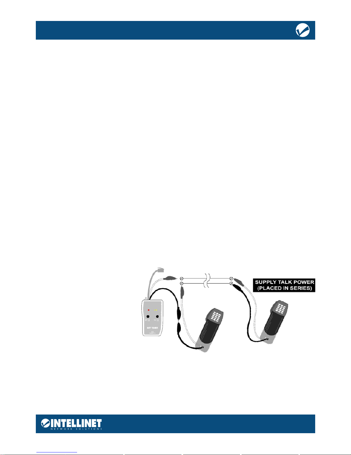
Supplying Talk Power
The Net Toner has a feature that allows users to communicate using telephone test sets,
even when a circuit is dead.
1. Using the test leads, connect
the Net Toner and a telephone
test set to the inactive circuit,
in series, as illustrated.
2. Flip the toggle switch on the
Net Toner to the Cont/ Talk
position.
3. Set the TALK BATT button
to the Enhanced (down)
position. This provides
additional battery power to
enable voice communication over the inactive circuit. You should now be able to
communicate using the telephone test sets.
Testing Cable Continuity
NOTE: Before testing for this, check line polarity to ensure that the line is not powered.
1. Connect the red and back alligator test leads to the cable you want to test.
2. Flip the toggle switch on the Net Toner to the CONT/TALK position.
 Loading...