

Intellinet 508018 User Manual

Table of Content
Table of Content.........................................................................................1
Introduction................................................................................................2
Product Specifications........................................................................2
Benefits and Key Features.................................................................3
Physical Parts and Panel of the Powerful Server...............................7
Package Contents..............................................................................9
Quick Installation.....................................................................................10
Hardware Installation........................................................................10
Check Your PC First.........................................................................11
Connect to the Web-Based Manager...............................................13
Web-Based Manager – Basic Settings.............................................15
Configuration Hierarchy...........................................................................21
Overview of Configuration Menu......................................................22
Network Settings..............................................................................23
Firewall Settings...............................................................................30
VPN Settings....................................................................................35
System Management........................................................................37
System Reports................................................................................43
User Management............................................................................48
NAS Management............................................................................50
FTP Server..............................................................................................64
Personal Web Server...............................................................................66
E-mail Server...........................................................................................67
Windows USB Printer Server...................................................................69
Appendix A..............................................................................................71
1

Introduction
Thank you for purchasing our innovative all-in-one solution---Powerful
Server appliance for your networking needs.
The SA integrates server services such as a Network Address Translator
(NAT), Virtual Private Network (VPN), SPI firewall, and networked storage
into one easy to manage device. The Powerful Server appliance allows a
group of trusted computers and networks to connect quickly and safely. With
the Powerful Server appliance, network managers and users can save time in
establishing some of the most common services done on servers costing
thousands of dollars.
Product Specifications
Connection Sharing
n Flexible Address Space for NAT service
n IP Alias
n Multiple NAT
Virtual Private Network
n PPTP Server / Client
Firewall
n Prevent Denial of Service (DoS) Attacks
n Packet/URL Filtering
n Access Control, Virtual Server
System Management
n Web-based Management for Configuring System
n Firmware Update via HTTP
n Reset To Factory Settings
n Event Alert and Logs
n System Information
2

Services
n DHCP Client/Server
n Proxy DNS
n RIP
n DDNS Client
n FTP Server
Network
n Programmable Static Route
n Network Protocols Supported: PPPoE, TCP, UDP, ICMP, ARP
PPP Authentication
n PAP, CHAP, MS CHAPv2
Real Time Clock
RAID Support
n Supports RAID 0, 1
File Sharing
n Supports CIFS,SMB, AppleTalk(AFP), NFS
User Management
n Local User Account Management
Power Management
n Support Mechanical Off/Soft Off/Sleeping/Working System States
Other Features
n Personal Web Server
n USB Printer Server
n USB Storage Sharing
n Personal POP E-Mail Server
Benefits and Key Features
Virtual Private Network
With Virtual Private Networking, an enterprise can establish a dedicated
tunnel among branch offices and/or mobile employees. All data is encrypted
and decrypted via the pre-defined dedicated tunnel. This prevents any
hackers from stealing private information in the public network. With this
3

functionality, any sub-network can be grouped as though they are in the same
network.
Firewall
The Powerful Server appliance provides a powerful firewall capable of
preventing hackers from attacking the gateway or internal network. Many
famous DoS attacks can be detected and prevented. Whenever an attack is
detected, the system will alert the network manager that an attack has
occurred. The network manager can then inspect the log information to find
the IP address that sent the packets.
Easy Installation
In order to facilitate the use of the Powerful Server appliance, the product
comes with default settings that most network managers can install it without
any modification. If the network manager needs to modify any of the settings,
the Powerful Server appliance provides an intuitive Web-based user
interface.
RAID (Redundant Array of Independent Disks)
RAID is a hard disk access technology that allocates space of disk drives that
utilize two or more drives in combination so as to increase fault tolerance and
improve overall performance. Powerful Server appliance supports 2 types of
RAID, RAID 0 and RAID 1.
n RAID 0 - Striped Disk Array without Fault Tolerance: Provides
data striping (spreading out blocks of each file across multiple disk
drives) but no redundancy. This improves performance but does not
deliver fault tolerance. If one drive fails then all data in the array is
lost. The size of this RAID type equal to sum of Disk 1 and Disk 2.
n RAID 1 - Mirroring Disk Array: A technique in which data is written
to two duplicate disks simultaneously. This way if one of the disk
drives fails, the system can instantly switch to the other disk without
any loss of data. The size of this RAID type equal to single Disk.
4

Network Attached Storage
Network-attached storage (NAS) is the concept of shared storage on a
network. NAS transfers data using industry standard file sharing protocols
such as CIFS, AFP, NFS and FTP. Files can be shared simultaneously by
clients regardless of the operating system they are using or the network
server they are attached to. This solution provides convenient common
storage resources.
Dynamic DNS
Dynamic DNS allows anyone wishing to reach your host by the name only.
Dynamic DNS will map that name to your current IP address, which changes
each time you dial your Internet service provider. With a URL that stays the
same all the time regardless of IP address your options become almost as
unlimited as a normal content provider like www.indiatimes.com or
www.yahoo.com.
USB Print Server
USB Print Server allows any computer in the network to share an USB printer.
It complies with USB 2.0 specifications. And the users can print from any
computer over a LAN.
Personal Web Server
The Personal Web Server enables users to host an information type website
from their appliance. Create your website and place it on the appliance for the
world to see. Use it in combination with our built-in DDNS client and anyone
with a broadband connection can have their very own website.
Personal POP E-mail Server
The Personal POP E-mail Server provides users the ability to run a personal
private e-mail server. Send e-mail you’re your registered domain name or just
create a DDNS account and have your personalized e-mail address.
FTP Server
FTP is the most secure, fastest, reliable method of transferring files. The FTP
5

server allows you full control over who can login to the Powerful Server
appliance, which files the user can access or they could upload data.
Power Management
We divide the power management function into three parts. These are Power
Down and Hard Disk Standby.
We’ll describe each part in detail below.
- Power Down
We turn the power down in several ways:
n Power Down by Web
Please select System Management -> Administrator Settings. In
Power Down field, to select the enable radio button and then click
the apply button.
n Power Down by press the power button
n Prompt Power Down
Please press and hold the power button at least 4 seconds.
- Hard Disk Standby
If the hard disk is idle for a while, we would like the hard disk to enter
standby mode to reduce the consumption of power. In the left menu,
select NAS Management -> RAID Initialization Wizard, in HD Power
Management Setting, please select the time in the ‘Turn Off hard disk’
field (Figure 1.2). If you select ‘none’, the hard disk will not enter the
standby mode even if it is always idle. If you select ’5 mins’, the hard disk
will enter standby mode once it is idle for more than five minutes.
6
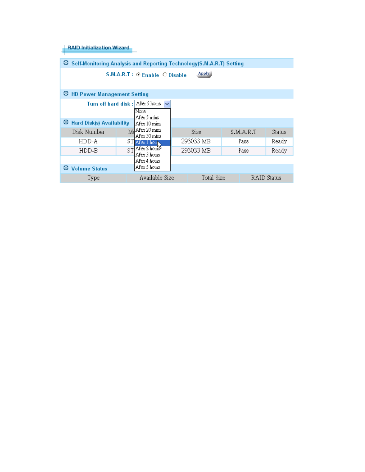
Figure 1.2
Physical Parts and Panel of the Powerful Server
n One WAN port: 10/100 Mbps
n WAN port MDI/MDIX switch
n Four LAN ports: 10/100 Mbps
n Four USB 2.0 port
n Reset Button
n Power Button
n Power Jack - DC 12V
n LEDs: Link/Activity LEDs for Each Ethernet Port, Power
LED, HD Access, HD Indicator & Packet Transmit/Receive
LEDs
7

WAN Port
The WAN port is used to connect to an ADSL/Cable modem for linking to the
Internet.
WAN MDI/MDIX Switch
The WAN MDI/MDIX switch is used to adjust the cable connection of the
WAN port. If the port is connected to hub, you should move the switch to the
“hub” side; if the port is connected to PC like machine, you should move the
switch to the “PC” side. As for the four LAN ports, there is no need to add
additional switches for each cable connection. This is because the LAN ports
support auto MDI/MDIX.
LAN Ports
The LAN ports are used to connect to a PC, server, hub, switch or other
network devices on the intranet.
Reset Button
If you forget your password and/or IP settings, you will not be able to access
the SA. You can use the Reset Button to restore the factory settings. To
initiate a reset, you must hold the button for at least 5 seconds.
The primary default settings are listed in the following table.
Configuration Item Default Settings
Administrator Username <empty>
Administrator Password admin
Internal IP address 172.16.1.1
Power Button
You can use the Power Button to turn on/off Powerful Server appliance.
8

Description of LEDs
Description of
Status Meaning
LEDs
Power
HD Indicator
Access Indicator Flash HD is reading/writing data
WAN/LAN
Link/Activity
10/100 Mbps
Throughput
On Power On
Off Power Off
On HD Abnormal
Off HD Normal
On Link up
Off Link down
Flash The interface is transmitting/receiving packets
On The network link is 100 Mbps WAN/LAN
Off The network link is 10 Mbps
No LED on
1 LED on Current transfer rate is > 10KB/s
2 LEDs on
3 LEDs on
Current transfer rate is < 10KB/s
Current transfer rate is >50KB/s
Current transfer rate is >100KB/s
4 LEDs on
Current transfer rate is >500KB/s
Package Contents
n Powerful Server
n Power Adapter and Power Cord
n Ethernet cable
n User Manual CD
n Quick Installation Guide
9

Quick Installation
This chapter will give you brief instructions on how to install the product. In
section 2.1, we will configure the hardware part of SA step by step. In section
2.2, we will check whether the IP address of your PC is assigned by DHCP.
Once we complete the installation of the SA hardware and checked your PC
settings, we will use the web-based management to configure the SA to suit
your network environment. In section 2.3, and 2.4, we will review all the
software settings. We will configure it to gain access to the Internet. If you
need additional help or advanced setting details, please refer to the
remaining chapters.
Hardware Installation
Please follow the steps below to install hardware:
1. Get the included Ethernet cable.
Connect one end of it to the ADSL/Cable modem and the other end
to the WAN port on the SA.
2. Get another Ethernet cable.
Connect one end of it to the PC or hub and the other end to one of
the LAN ports on the SA.
3. Turn the ADSL/Cable modem on. Note: Cable modem users MUST
disconnect the cable modem from the wall outlet for at least 2
minutes before turning it on again.
If there are more PCs or hubs to be connected, please repeat step
2.
4. Connect the included power adapter to the power socket on the SA
and then plug the power adapter into a wall outlet.
5. Turn on the SA.
If the link LED of the WAN port is not ON, switch the WAN
MDI/MDIX switch to the alternate setting.
The hardware installation is now complete.
10
Check Your PC First
Please check the following settings on your PC:
Do not assign an IP address to your PC.
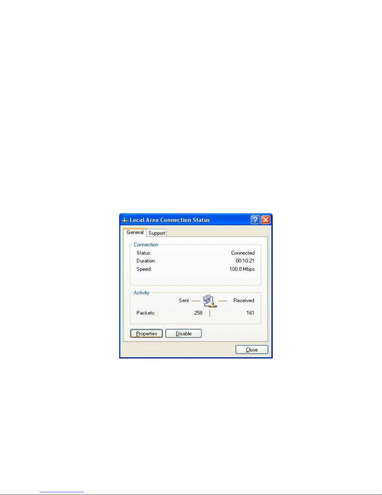
1. Please select sequentially: In Start menu -> Settings -> Control
panel -> Network connections -> Local Area Connection. Then a
“Local Area Connection Status” window shows up. (Figure 2.2a)
2. Click the Properties button in Local Area Connection Status. Then
the “Local Area Connection Properties” window shows up. (Figure
2.2b)
3. Select Internet protocol (TCP/IP) item and then click the Properties
button. The “Internet Protocol (TCP/IP) Properties” window shows
up. (Figure 2.2c)
4. Select the “Obtain an IP address automatically” radio button then
click the OK button.
11
Figure 2.2a
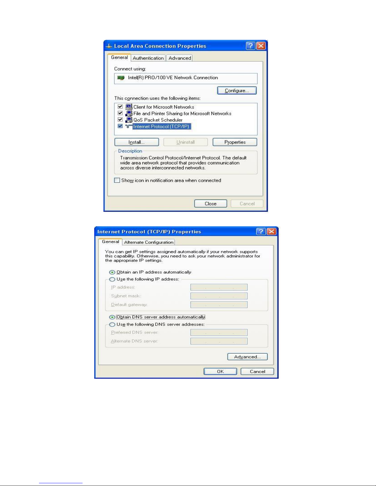
Figure 2.2b
`
Figure 2.2c
12
Connect to the Web-Based Manager
Please follow the steps to connect to the web-based manager:
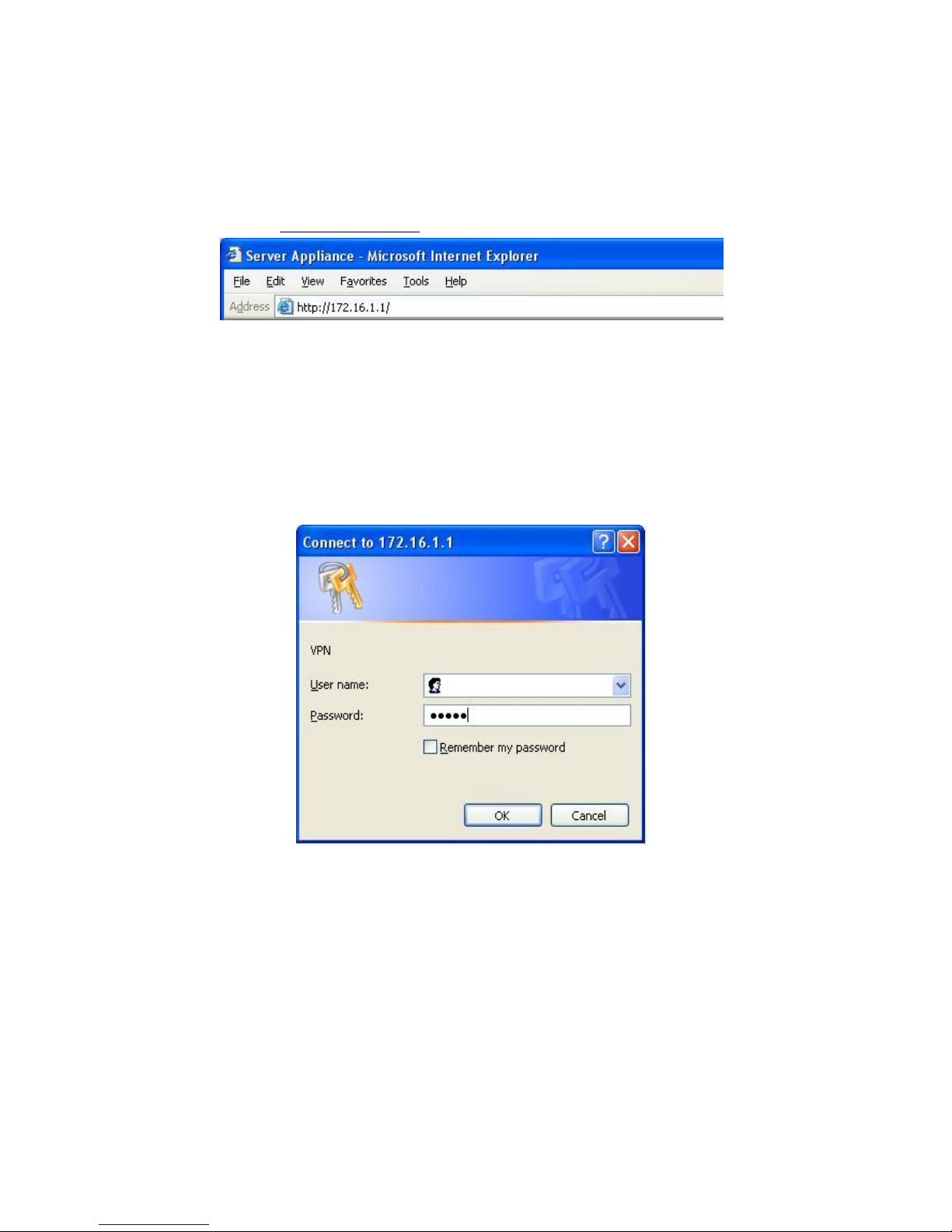
1. Open a browser on the PC that is DIRECTLY connected to the SA.
Type “http://172.16.1.1” in address field. And then press Enter key.
2. An authentication window shows up to prompt you to type the
username and the password.
3. Leave the username blank and type “admin” as a password.
(Figure 2.3a.)
4. Then press OK button. The default web page will appear like Figure
2.3b.
13
Figure 2.3a
14
Figure 2.3b
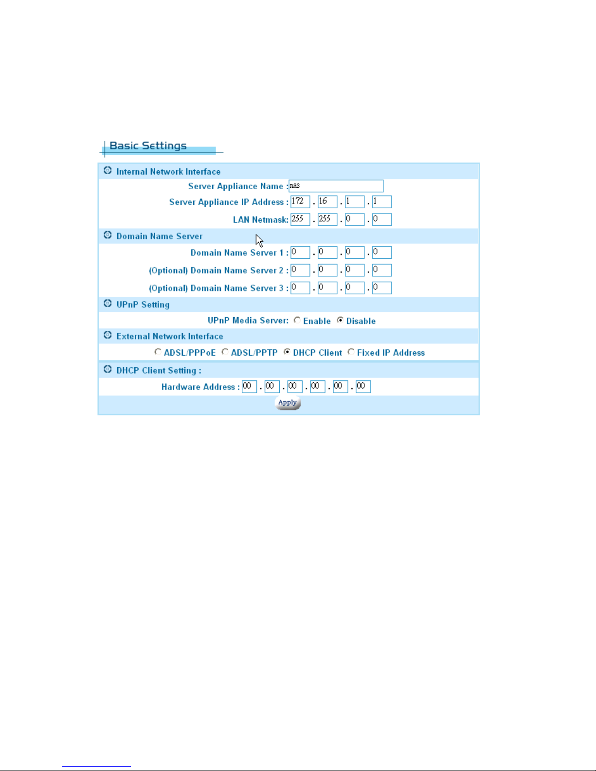
Web-Based Manager – Basic Settings
Start to configure your network environment by clicking the Basic Settings in
left menu. The Basic Settings page is shown as Figure 2.4a.
Figure 2.4a
The Basic Settings page contains Network Policy, Internal Network
Interface, Domain Name Server, and External Network Interface. We
describe these settings below in detail. You must click the apply button after
you finish inputting the settings. You will see a rebooting window as Figure
2.4b. During the rebooting phase, do not turn off or unplug the Powerful
Server appliance.
15

Figure 2.4b
•Internal Network Interface
The default settings are:
n Host Name: “SA”
n Private IP: “172.16.1.1”
n Private IP Netmask: “255.255.0.0”
According to the default settings, we will assign the LAN to network
“172.16.1.x” You can add more detailed configurations later in section 4.1
DHCP Server settings.
For the Network Address Translation (NAT) application, the private
network address should be set in the following address range reserved by
the Internet Assigned Numbers Authority (IANA).
Class Address Range
A Class 10.0.0.0/10.255.255.255
B Class 172.16.0.0/172.31.255.255
C Class 192.168.0.0/192.168.255.255
Domain Name Server•
n Most of the time this information is not needed, as your ISP will
automatically provide the information.
n Please ask the DNS IP address from your ISP if one is required.
16
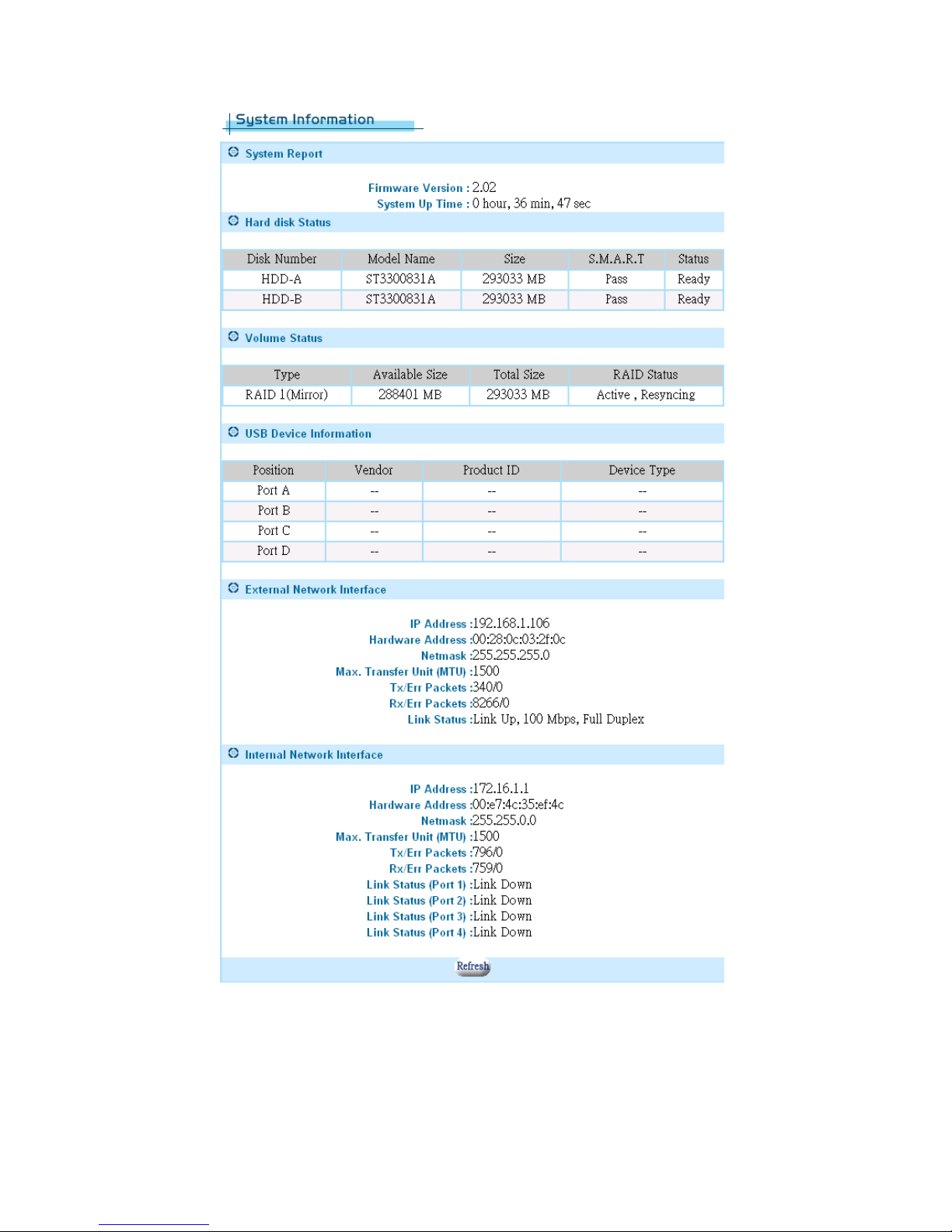
External Network Interface•
External network interface includes ADSL/PPPoE , DHCP Client and
Fixed IP Address settings. Make sure that the system information
webpage shows that your Link status is ‘Link Up’. If not, please check
your connection and/or switch the MDX switch located next to your WAN
port. We have to choose one of the three ways to configure the external
network interface. They are illustrated as follows:
Example 1: If you are connecting through a fixed IP address from the ISP.
Example 2: If you are connecting through a dynamic IP address from ISP.
Example 3: If you usually enter a username and password to access the
Internet.
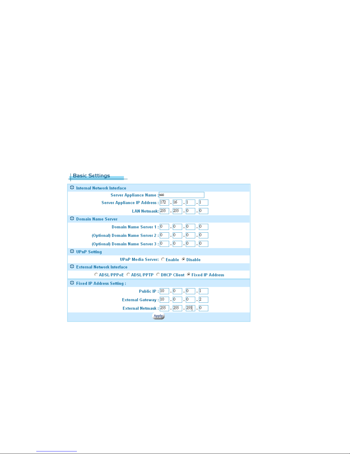
Example 1: Fixed IP Address Settings•
If you have a fixed IP address from your ISP to access the Internet, please
follow the steps below:
1. Select the Fixed IP Address radio button.
2. Enter the Public IP address.
17
3. Enter the External Gateway.
4. Enter the External Netmask.
5. Click the apply button.
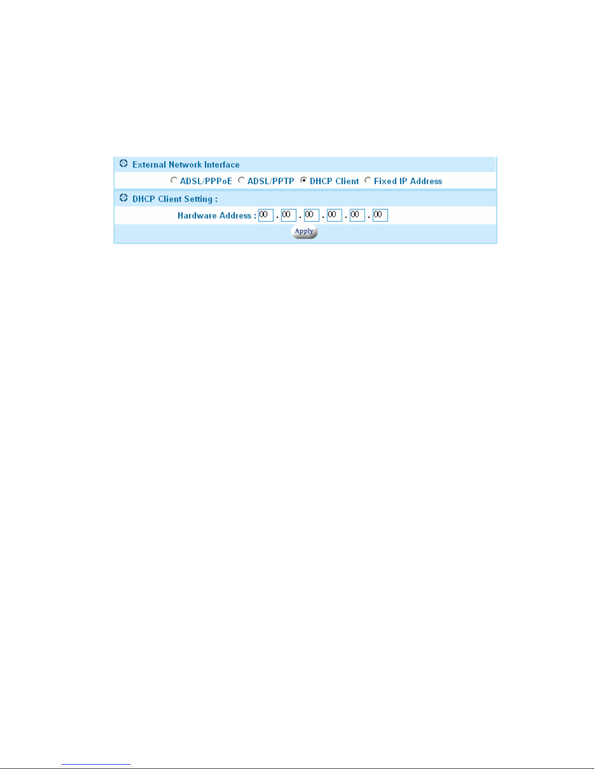
Example 2: DHCP Client / Cable Modem•
If you have a dynamic IP address from your ISP to access the Internet,
please select the DHCP Client radio button. Once the external IP
address is obtained via the DHCP protocol, there is no need to give an
external IP address, external gateway address or netmask. The DHCP
server will dynamically assign these fields. In general, you should choose
this option if you are connecting the Powerful Server appliance to a cable
modem. Note: Cable modem users MUST disconnect the cable modem
from the wall outlet for at least 2 minutes before turning it on again. Some
cable modem connections need you to provide specific hardware address.
For the case, you should fill your hardware address that you get from your
ISP provider in Hardware Address field to override the original hardware
address. However, it does not update the original hardware address
stored in EEPROM. If you would not like to override the hardware address,
you should set each field of the Hardware Address to zero “00”.
18
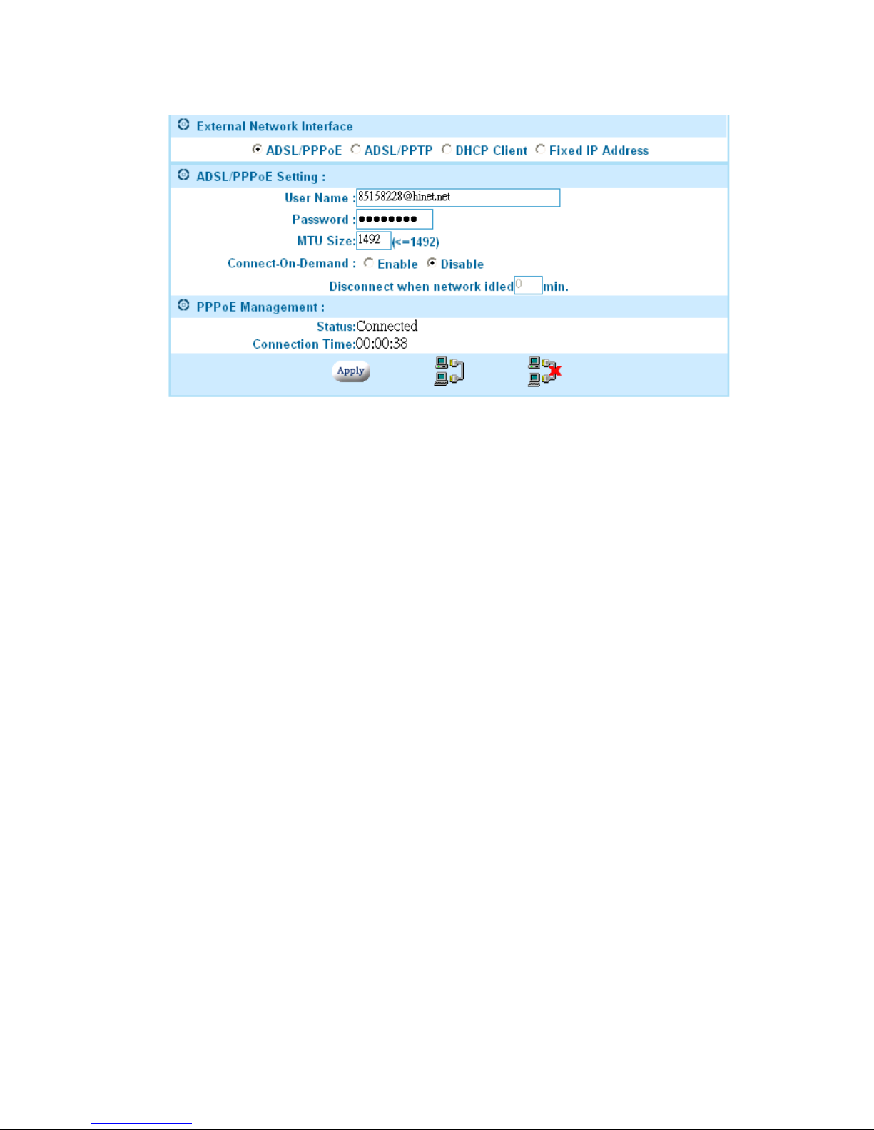
•Example 3: ADSL Connection
Most ADSL connections do not give you a fixed IP address. In this case,
you must enter the user name and password provided by your ISP for
authentication. Please follow the steps below.
1. Please select the ADSL/PPPoE radio button.
2. In ADSL/PPPoE Setting: Enter the User Name and Password.
3. Click the apply button to save your settings.
After completing your configuration, each time the SA boots, it will try to
connect with your ISP and the ISP will assign the Powerful Server
appliance an external IP address. Once successfully connected, the
Status field should reflect this. If the Status is still the same, check to make
sure that the username, password, cables, etc. are all correct.
19
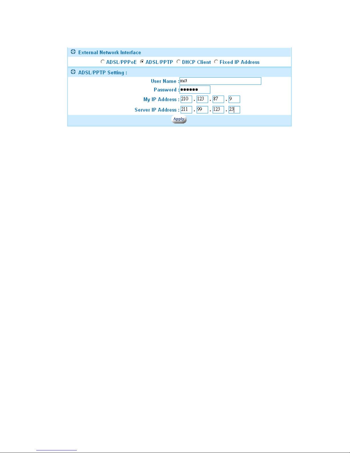
Example 4: ADSL/PPTP Client Setting•
If your ISP provides a PPTP server, you could set up the PPTP client
here.
Please follow the steps:
1. Select ADSL/PPTP radio button.
2. Enter the user name. (You get this from your ISP)
3. Enter the password. (You get this from your ISP)
4. Enter the IP address of your host in My IP Address.
5. Enter the IP address of the server in Server IP Address.
In the following chapters, we will cover more details of configuring the SA.
20

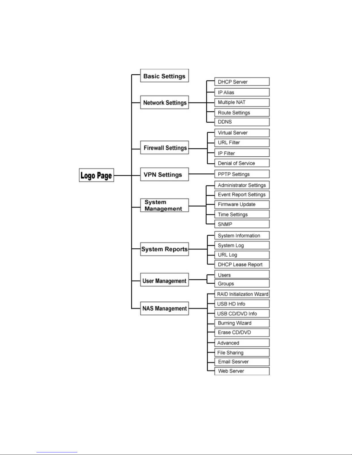
Configuration Hierarchy
This chapter gives you an overview of all the configuration options available.
The Powerful Server appliance is a multifunction product. The section3.1
explains the corresponding settings for each function. And in section3.2, we
describe the power management in detail.
There are eight main categories in configuration menu, Basic settings,
Network settings, Firewall settings, VPN settings, System management,
System reports, User management and NAS management. Each item
has advanced configurations. See Figure 3.1.
21
Overview of Configuration Menu
Figure 3.1
22
 Loading...