

Intellinet 507622, 507738, 507745, 507769, 507776 User Manual
...
INT-LCD-KVM-SWITCH_UM-0317_REV5.01
LCD KVM Switch
User Manual
Models 507622, 507738, 507745, 507769, 507776, 507844,
507882, 507899, 507905, 507912, 507936
Model Shown: 507622

LCD VGA/DVI/Cat5 KVM Switch
2
LCD KVM Switch User Manual
Compliance Statements
U.S. Federal Communications Commission (FCC) Interference Statement
This product has been tested and found to comply with FCC regulations Class B (Class B) digital device and FCC
specifications Details of Section 15. These limits are designed to provide reasonable protection against harmful
interference in a residential installation. This equipment generates, uses and can radiate radio frequency energy, and if
not installed and used in accordance with the instructions may cause harmful interference to radio communications.
However, there is no guarantee that interference will not occur in a particular installation. If this equipment does cause
harmful interference to radio or television reception, which can be determined by turning the equipment off and on, the
user is encouraged to try to correct the interference by one or more of the following measures: reorient or relocate the
receiving antenna; increase the separation between the equipment and the receiver; connect the equipment to an outlet
on a circuit different from the receiver; or consult the dealer or an experienced radio/TV technician for help.
CE / R&TTE
English: This device complies with the requirements of R&TTE Directive 1999/5/EC. The Declaration of Conformity is available at:
Deutsch: Dieses Gerät enspricht der Direktive R&TTE Direktive 1999/5/EC. Die Konformitätserklärung für dieses Produkt finden Sie unter:
Español: Este dispositivo cumple con los requerimientos de la Directiva R&TTE 1999/5/EC. La declaración de conformidad esta disponible en:
Français: Cet appareil satisfait aux exigences de la directive R&TTE 1999/5/CE. La Déclaration de Conformité est disponible à:
Polski: Urządzenie spełnia wymagania dyrektywy R&TTE 1999/5/EC. Deklaracja zgodności dostępna jest na stronie internetowej producenta:
Italiano: Questo dispositivo è conforme alla Direttiva 1999/5/EC R&TTE. La dichiarazione di conformità è disponibile al:
intellinetnetworks.com
Waste Electrical & Electronic Equipment
Disposal of Electronic Equipment (applicable in the E.U. and countries with separate collection systems)
English: This symbol on the product or its packaging indicates that this product shall not be treated as household waste.
Instead, it should be taken to an applicable collection point for the recycling of electrical and electronic equipment. By
ensuring this product is disposed of correctly, you will help prevent potential negative consequences to the environment
and human health, which could otherwise be caused by inappropriate waste handling of this product. If your equipment
contains easily removable batteries or accumulators, dispose of these separately according to your local requirements.
The recycling of materials will help to conserve natural resources. For detailed information about recycling this product,
contact your local city office, your household waste disposal service or the shop where you purchased this product. In
countries outside of the EU: If you wish to discard this product, contact your local authorities and ask for the correct
manner of disposal.
Deutsch: Dieses auf dem Produkt oder der Verpackung angebrachte Symbol zeigt an, dass dieses Produkt nicht mit dem
Hausmüll entsorgtwerden darf. In Übereinstimmung mit der Richtlinie 2002/96/EG des Europäischen Parlaments und des
Rates über Elektro- und Elektronik-Altgeräte (WEEE) darf dieses Elektrogerät nicht im normalen Hausmüll oder dem
Gelben Sack entsorgt werden. Wenn Sie dieses Produkt entsorgen möchten, bringen Sie es bitte zur Verkaufsstelle
zurück oder zum RecyclingSammelpunkt Ihrer Gemeinde.
Español: Este símbolo en el producto o su embalaje indica que el producto no debe tratarse como residuo doméstico. De
conformidad con la Directiva 2002/96/CE de la UE sobre residuos de aparatos eléctricos y electrónicos (RAEE), este
producto eléctrico no puede desecharse se con el resto de residuos no clasificados. Deshágase de este producto
devolviéndolo a su punto de venta o a un punto de recolección municipal para su reciclaje.
Français: Ce symbole sur Ie produit ou son emballage signifie que ce produit ne doit pas être traité comme un déchet
ménager. Conformément à la Directive 2002/96/EC sur les déchets dʼéquipements électriques et électroniques (DEEE),
ce produit électrique ne doit en aucun cas être mis au rebut sous forme de déchet municipal non trié. Veuillez vous
débarrasser de ce produit en Ie renvoyant à son point de vente ou au point de ramassage local dans votre municipalité, à
des fins de recyclage.
Italiano: Questo simbolo sui prodotto o sulla relativa confezione indica che il prodotto non va trattato come un rifiuto
domestico. In ottemperanza alla Direttiva UE 2002/96/EC sui rifiuti di apparecchiature elettriche ed elettroniche (RAEE),
questa prodotto elettrico non deve essere smaltito come rifiuto municipale misto. Si prega di smaltire il prodotto
riportandolo al punto vendita o al punto di raccolta municipale locale per un opportuno riciclaggio.
Polski: Jeśli na produkcie lub jego opakowaniu umieszczono ten symbol, wówczas w czasie utylizacji nie wolno wyrzucać
tego produktu wraz z odpadami komunalnymi. Zgodnie z Dyrektywą Nr 2002/96/WE w sprawie zużytego sprzętu
elektrycznego i elektronicznego (WEEE), niniejszego produktu elektrycznego nie wolno usuwać jako nie posortowanego
odpadu komunalnego. Prosimy o usuniecie niniejszego produktu poprzez jego zwrot do punktu zakupu lub oddanie do
miejscowego komunalnego punktu zbiórki odpadów przeznaczonych do recyklingu.

LCD VGA/DVI/Cat5 KVM Switch
3
Table of Contents
COMPLIANCE STATEMENTS ................................................................................................................................................. 2
PRODUCT MODELS & DESCRIPTIONS .................................................................................................................................. 4
PACKAGE CONTENTS & MANUAL INFORMATION ............................................................................................................... 4
A NOTE TO THE USER .......................................................................................................................................................... 4
DESCRIPTION OF SYMBOLS .................................................................................................................................................. 4
CHAPTER 1 ‒ INTRODUCTION ....................................................................................................................................... 5
1.1 PRODUCTS OVERVIEW ................................................................................................................................................... 5
1.1.1 Hardware Requirements ........................................................................................................................................ 5
1.1.2 Supported Operating Systems ................................................................................................................................ 6
1.2 PARTS ............................................................................................................................................................................. 7
1.2.1 Front View .............................................................................................................................................................. 7
1.2.2 Modular Switch Rear Views ................................................................................................................................... 8
1.3 VIEWS AND DIMENSIONS ............................................................................................................................................... 9
CHAPTER 2 ‒ HARDWARE INSTALLATION ............................................................................................................... 10
2.1 STACKING AND INSTALLATION NOTES ........................................................................................................................ 10
2.2 STANDARD RACK MOUNTING ..................................................................................................................................... 10
2.3 KVM MODULE ASSEMBLY & DISASSEMBLY .............................................................................................................. 11
2.4 KEYBOARD DISASSEMBLY .......................................................................................................................................... 12
2.5 EXPANSION MODULE INSTALLATION .......................................................................................................................... 12
2.6 SINGLE DEVICE INSTALLATION ................................................................................................................................... 14
2.6.1 VGA Port KVM Module Installation .................................................................................................................... 14
2.6.2 Cat5 Port KVM Module Installation .................................................................................................................... 15
2.6.3 DVI Port KVM Module Installation ..................................................................................................................... 16
2.7 CASCADE DEVICE INSTALLATION ............................................................................................................................... 17
2.7.1 VGA Port LCD KVM Switch Cascade ................................................................................................................. 17
2.7.2 Cat5 Port LCD KVM Switch Cascade ................................................................................................................. 18
CHAPTER 3 ‒ BASIC OPERATIONS ............................................................................................................................. 19
3.1 HOT-SWAP ................................................................................................................................................................... 19
Hot-Swap Console Port ................................................................................................................................................ 19
3.2 CONNECTION PORT SELECTION ................................................................................................................................... 19
3.2.1 Manual Switching: ............................................................................................................................................... 19
3.2.2 OSD Menu Screen Selection ................................................................................................................................ 19
3.2.3 Hot Key Selection ................................................................................................................................................. 20
3.3 POWER OFF AND RESTART .......................................................................................................................................... 20
3.4 OPENING / CLOSING / LOCKING THE LCD ................................................................................................................... 20
CHAPTER 4 ‒ ON-SCREEN DISPLAY (OSD) OPERATIONS ................................................................................... 21
4.1 OSD LOGIN .................................................................................................................................................................. 21
4.2 OSD HOT KEY ............................................................................................................................................................. 21
4.3 OSD MAIN MENU ........................................................................................................................................................ 21
4.4 OSD MAIN SCREEN HEADINGS ................................................................................................................................... 21
4.5 OSD FUNCTIONS .......................................................................................................................................................... 21
4.5.1 F1:GOTO .......................................................................................................................................................... 22
4.5.2 F2:SCAN .............................................................................................................................................................. 22
4.5.3 F3:LIST ................................................................................................................................................................ 22
4.5.4 F4 QV ................................................................................................................................................................... 23
4.5.5 F5 EDIT ............................................................................................................................................................... 23
4.5.6 F6:SET ................................................................................................................................................................. 23
APPENDIX ........................................................................................................................................................................... 27
A‒1 GENERAL SAFETY INSTRUCTIONS ............................................................................................................................. 27
A‒2 CABINET INSTALLATION ............................................................................................................................................ 27
A‒3 SPECIFICATIONS ......................................................................................................................................................... 28
A.3.1 VGA Series LCD KVM Switch ............................................................................................................................. 28
A.3.2 Cat5 Series LCD KVM Switch ............................................................................................................................. 29
A.3.3 DVI Series LCD KVM Switch .............................................................................................................................. 30
A.3.4 LCD Module Specifications ................................................................................................................................. 31
WARRANTY ....................................................................................................................................................................... 32
NOTES .................................................................................................................................................................................. 33
LCD VGA/DVI/Cat5 KVM Switch
4
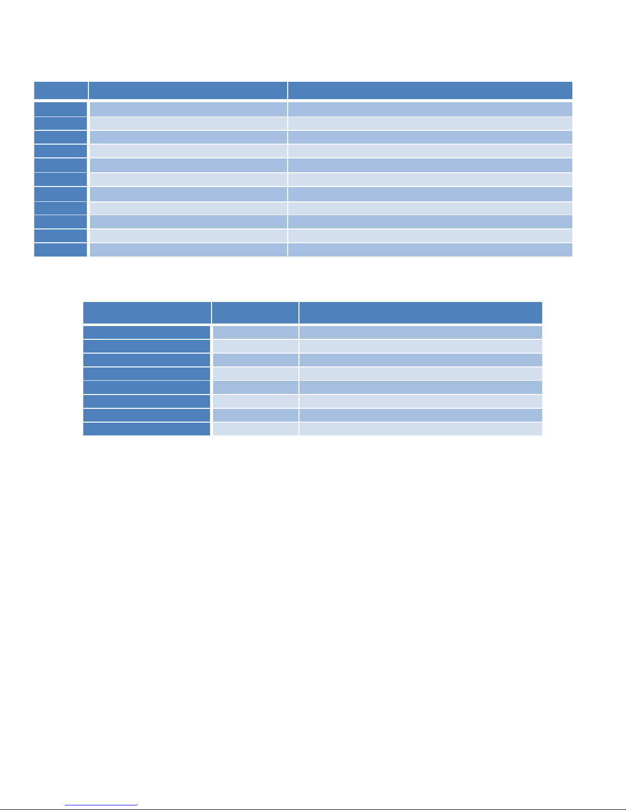
Product Models & Descriptions
Package Contents & Manual Information
Name
Quantity/Unit
Description
LCD KVM Console
1 pc.
LCD Computer
KVM Cables
N pc.
Cable qts. vary based on product descr.
Power Supply
1 pc.
Built-in power supply
Power Cable
1 pc.
Standard 1.8 m (5.9 ft.) power cord
Instructions
1 pc.
Paper manual
Mounting Brackets
2 pcs.
LCD KVM single-mount bracket
Lock ear
2 pcs.
Fixing rear panel
Screw-Install Kit
1 pc.
Screw-in mounting bracket
• Ensure that all parts are present and free from damage. If parts are missing or damaged, contact your Intellinet
dealer or distributor.
• Make sure to read this manual carefully before installing and operating the Intellinet LCD KVM Switch. Only
professionals should install this product.
A Note to the User
From time to time, Intellinet may modify and/or alter the information, documentation and specifications contained in this
manual, with or without prior notice. If the software needs to be updated after purchase, the user and/or her or his
dealer/distributor will be responsible for all necessary service and repair. The user is responsible for correcting any radio
or television interference that this equipment may cause. Make sure to set the voltage correctly before use. Intellinet will
not be liable for any damage resulting from incorrect selection of operating voltage.
A typical Liquid Crystal Display (LCD) has millions of pixels. A defective pixel is one that is off or does not display the
correct color, which may develop if the screen absorbs a slight impact during transportation or even in the process of
manufacturing. It is normal for a product with an LCD screen to arrive to the consumer with a few of these defects. The
user should contact her or his dealer/distributor in the event that there is more damage than described here.
Description of Symbols
• [ ] Brackets around a word indicate that the user must complete a keyboard action based on the text in the
brackets. For example, [Enter] indicates that the user needs to press the "Enter" key. When more than one key
needs to be pressed at the same time, the manual denotes this command by joining a plus sign between the two
keys (e.g., [Ctrl+Alt]).
• 1. Numbers indicate the operating steps that are necessary to complete a function.
• ✚ indicates that the information is for the user's reference but is not essential to the procedure.
• ✪ The star-in-the-circle symbol indicates that the information is very important.
Model
Name
Description
507622
Rackmount 17" LCD Console
17-Inch LCD Panel, 1U, Modular System
507738
Rackmount 19" LCD Console
19-Inch LCD Panel, 1U, Modular system
507745
Rackmount 19" LCD Console DVI
19-Inch LCD Panel, 1U, DVI, Modular system
507769
VGA 1-Port Cable for KVM Console
PS2, USB and VGA Connectors
507776
Modular 8-Port VGA KVM Switch
For Use with Intellinet Product Numbers 507622 or 507738
507844
Modular 16-Port VGA KVM Switch
For Use with Intellinet Product Numbers 507622 or 507738
507822
Modular 8-Port CAT5 VGA KVM Switch
For Use with Intellinet Product Numbers 507622 or 507738
507899
Modular 16-Port CAT5 VGA KVM Switch
For Use with Intellinet Product Numbers 507622 or 507738
507905
DVI 1-Port Cable for KVM Console
PS2, USB and VGA Connectors
507912
Modular 8-Port DVI KVM Switch
For Use with Intellinet Product Number 507745
507936
IP-Function Module for KVM Switches
For Use with Intellinet Modular KVM Console/Switch Range
LCD VGA/DVI/Cat5 KVM Switch
5
Chapter 1 – Introduction
1.1 Products Overview
1.1.1 Hardware Requirements
1.1.1.1 Console
• Rear two USB-A keyboard and mouse ports
• Pre-set USB-A type keyboard and mouse
• A set of USB interface mice
• A set of USB interface keyboards
• Single-ended extension cable (optional)
• IP remote control terminal 1000M network interface (optional installation)
1.1.1.2 Computer
The following devices must be installed on each computer:
• A VGA or DVI video display card
• USB-A connection port
• PS2 / PS2 keyboard, mouse ports
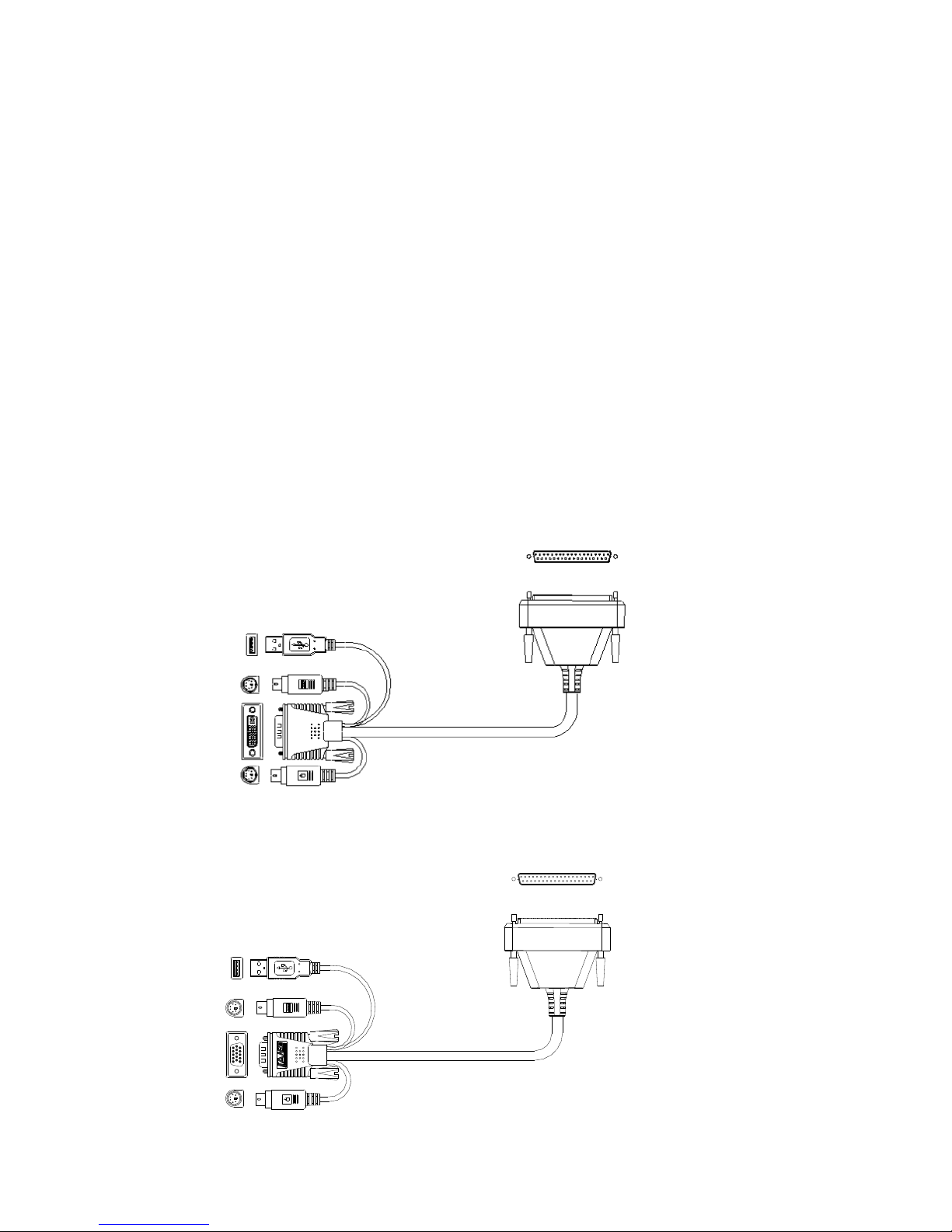
1.1.1.3 Cables
KVM equipment provides five kinds of connection cables according to the user's product:
• LCD KVM switch single-port DVI cable
Computer-side DVI-I & USB
(Type-A) + PS2 keyboard (purple)
+ PS2 mouse (green) to Parallel
(DB37P)
• LCD KVM switch single port VGA cable
Computer-side VGA & USB
(Type-A) + PS2 keyboard (purple)
+ PS2 mouse (green) to Parallel
LCD VGA/DVI/Cat5 KVM Switch
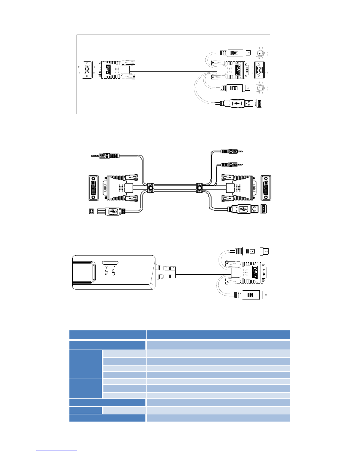
6
• LCD KVM switch VGA cable
VGA & USB
(Type-A) + PS2
keyboard (purple)
+ PS2 mouse
(green) to VGA
• LCD KVM switch DVI cable
DVI-I & USB
(Type-A) + Audio
• Cat5 to VGA connection Dongle
VGA + PS2
keyboard (purple) +
PS2 mouse (green)
to Cat5 port
1.1.2 Supported Operating Systems
System
Version
Windows
Windows 2000/XP/2003/2008/Vista/7/10
Linux
Red Hat
9.0 or higher, Fedora and above, RHEL AS 4, RHEL 5
SuSE
10/11.1, Open SUSE 10.2; SLES 10 SP1
Debian
3.1 / 4.0
Ubuntu
7.04/7.10
UNIX
AIX
4.3 or higher
FreeBSD
5.5 or higher
Sun Solaris
8 or higher
Mac
OS 9.0 to 10.6
Novell
Netware
6.0 or higher
DOS
6.2 or later
LCD VGA/DVI/Cat5 KVM Switch
7
1.2 Parts
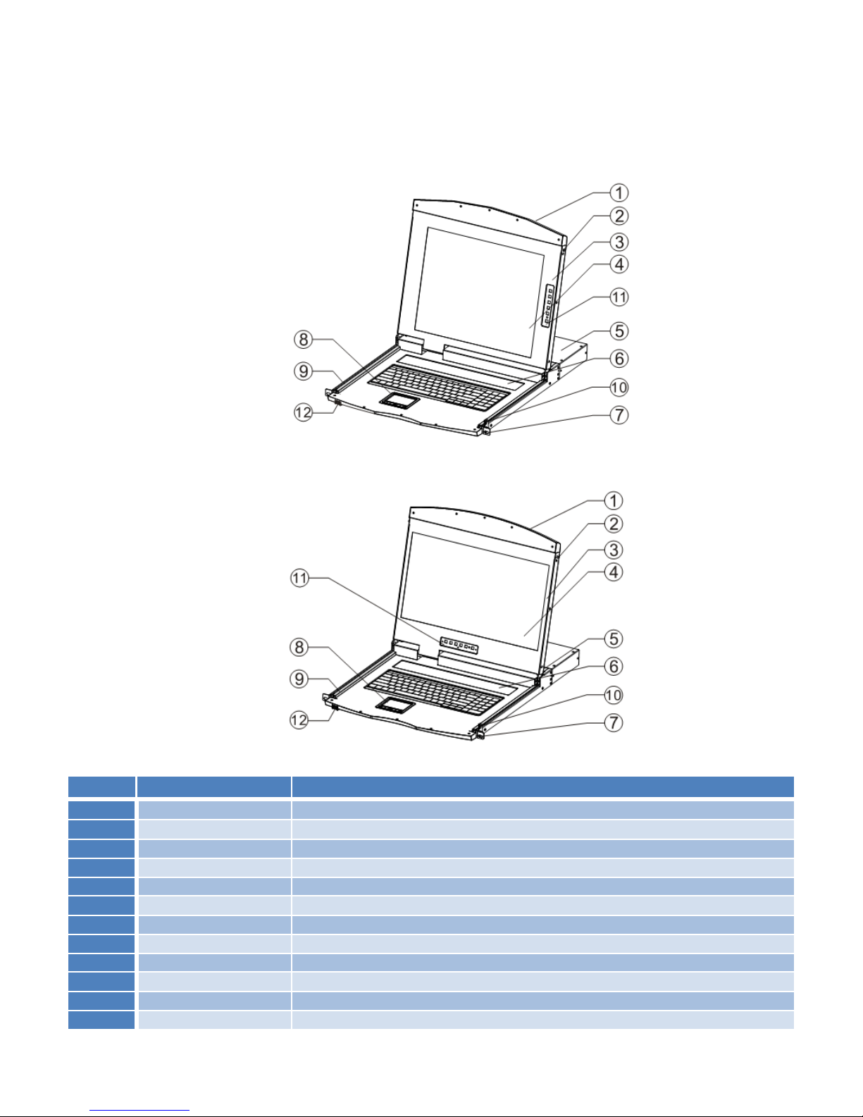
1.2.1 Front View
The are two different sizes of LCD screens, as shown below. Refer to the chart for a description of the numeric
values for each graphic.
17" Model
19" Model
Number
Part
Function Description
1
Upper Handle
Pull the handle, slide the LCD module out and push it in
2
Lock
Locks the LCD module; pull out module first, then push into the automatic lock
3
LCD Screen Cover
Opens or closes with the handle; opening and closing angle of 0° – 100°
4
LED Screen
17" or 19" LED/LCD screen – Later referred to as On Screen Displa (OSD)
5
KVM Module
KVM modules can be easily removed and replaced
6
KVM Key Panel
Press this key to enter to manual switch function
7
Front Mount Brackets
For installation into cabinets and racks with screws
8
Touch Mouse Pad
KVM console mouse; can control the computer's operations
9
Slide Rails
LCD module sliding track
10
Keyhole
Corresponds to the latch of the LCD module
11
LCD Keypad Panel
Used to control the LED screen display adjustment and switch
12
Front USB Port
Used to access an external USB keyboard or mouse
LCD VGA/DVI/Cat5 KVM Switch
8
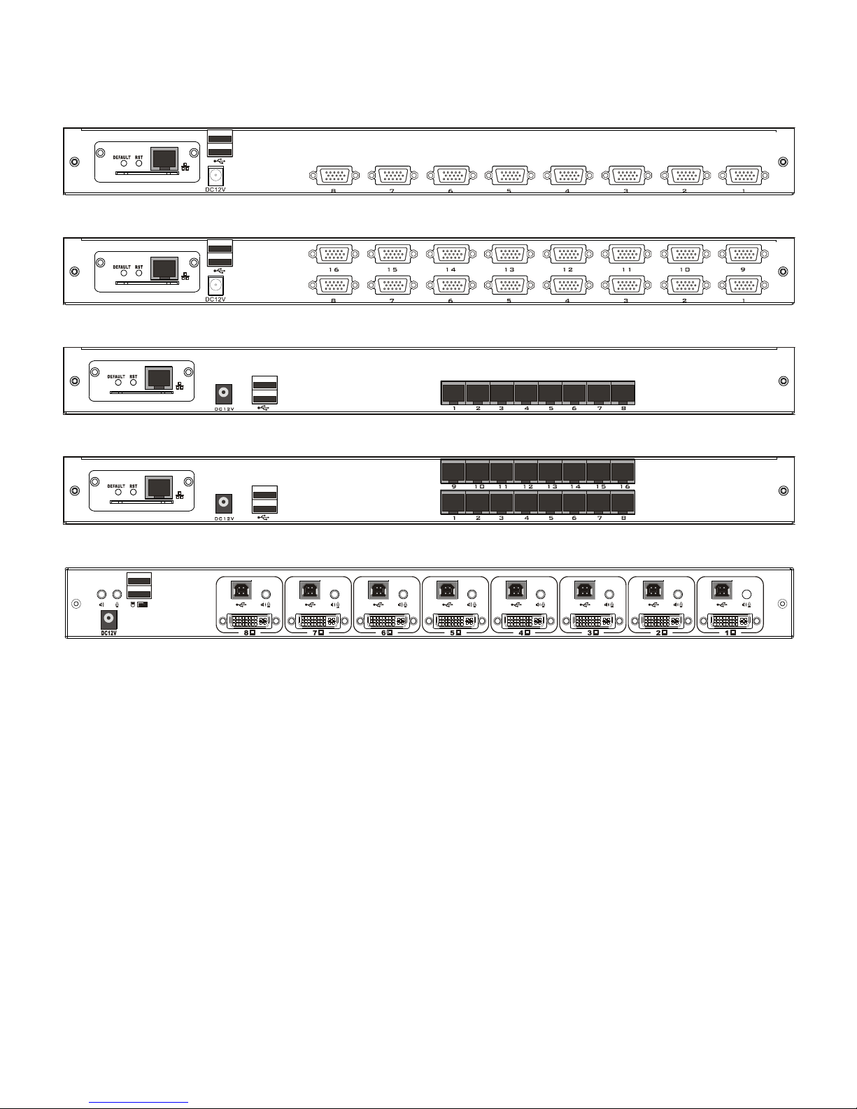
1.2.2 Modular Switch Rear Views
This section shows the available connection types of the Intellinet Removable KVM Switch Modules. Both the
VGA and Cat5 switch types can be optionally configured with Remote Control IP as the images describe.
LCD KVM 8-port VGA Switch
LCD KVM 16-port VGA Switch
LCD KVM 8-port Cat5 Switch
LCD KVM 16-port Cat5 Switch
LCD KVM 8 port DVI Switch
LCD VGA/DVI/Cat5 KVM Switch
9
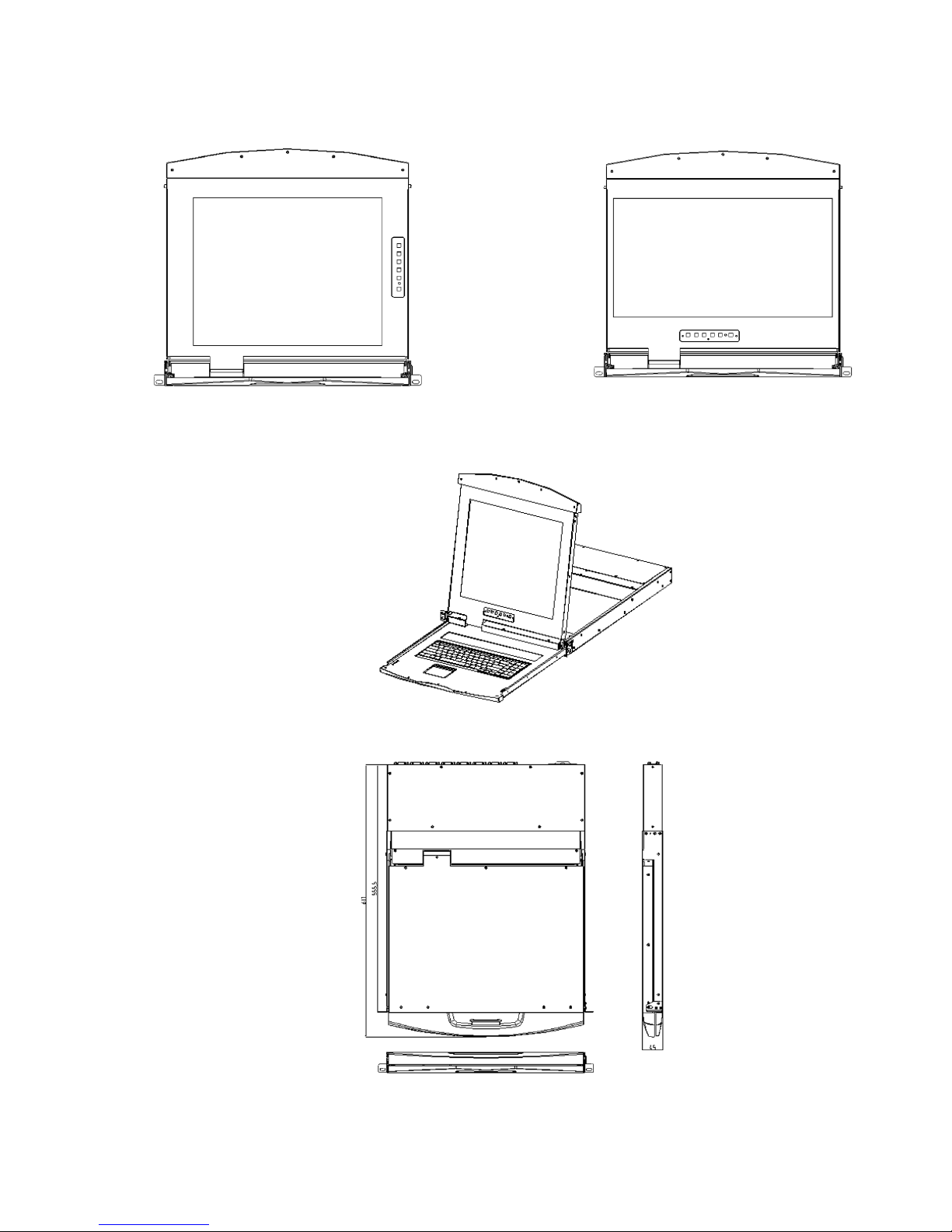
1.3 Views and Dimensions
4:3 Screen – 17" 16:9 Screen – 19"
Single-Rail LCD KVM Console
Single–Rail Multi-Port KVM Console Dimensions
LCD VGA/DVI/Cat5 KVM Switch
10
Chapter 2 – Hardware Installation
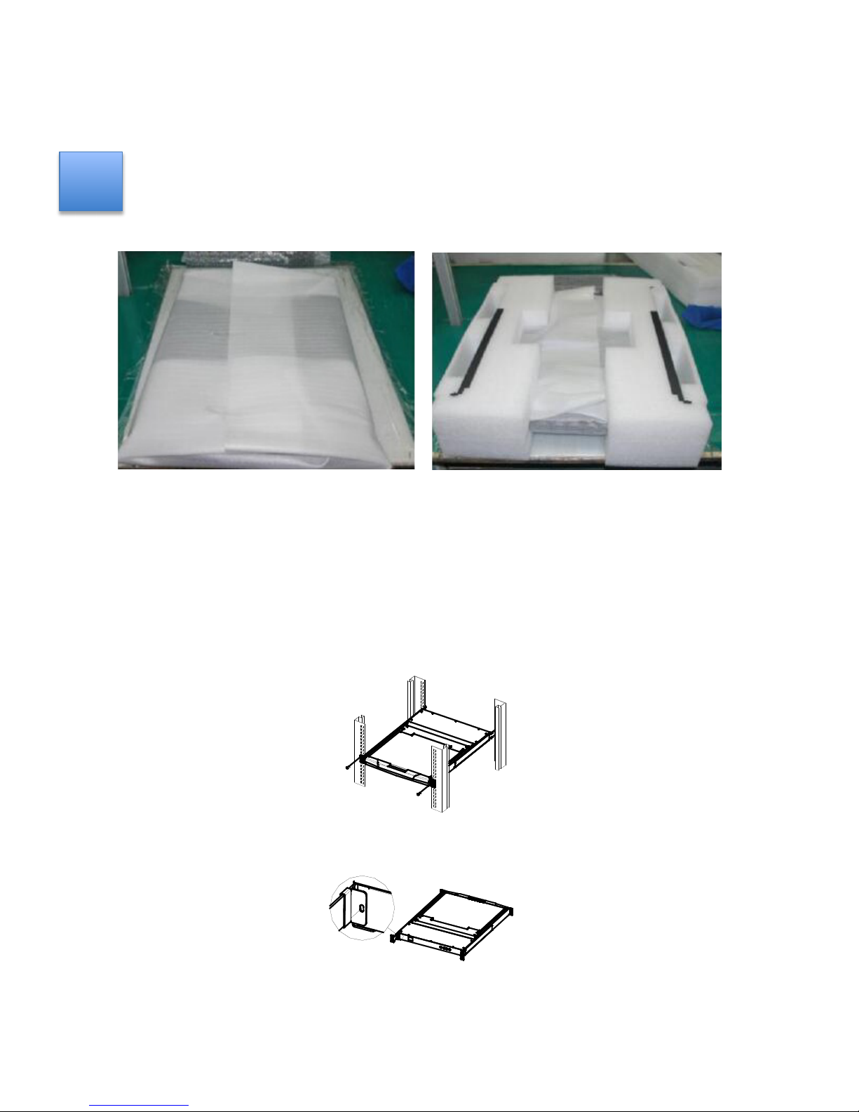
2.1 Stacking and Installation Notes
1. Before proceeding, refer to the important safety information regarding the placement of the LCD KVM
switch, which is listed in the appendix.
2. Before installation, make sure that all the devices connected to the power supply are turned off. Unplug
all power cables from the computer.
3. The LCD KVM switch is packed with stuffing to protect it during transportation and movement. Make
sure the equipment is free from all protective films and fillers before mounting.
Place the LCD KVM switch in a suitable area that will sufficiently and securely support the weight of the equipment plus
additional cables. Make sure that the area is clean and free from other debris that can affect the ventilation and normal
operation of the switch.
2.2 Standard Rack Mounting
1. Remove the mounting brackets and fasten the front bezel to the frame with screws. Slide the back plate with the
rear flange toward the rack until the flange is against the chassis. Then use the screws to secure the rear flange
to the chassis.
2. Slide the LCD KVM unit onto the support flange. Secure the front of the switch to the front of the rack with the
screws provided in the package.
3. Slide the rear-connecting slide bracket along the side rails until it reaches the rear of the switch.
4. Use the screws provided in this package to secure the strip to the rear of the switch.
✪
LCD VGA/DVI/Cat5 KVM Switch
11
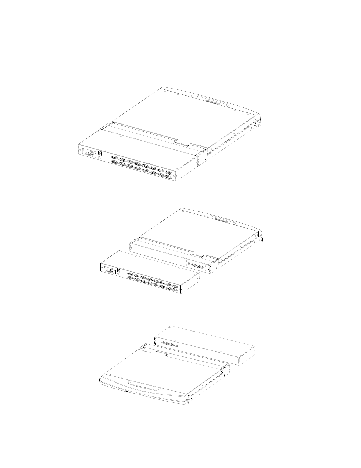
2.3 KVM Module Assembly & Disassembly
The Intellinet series of KVM Switches utilizes an LCD screen, keyboard and mouse with detachable, modular switch
components. This design allows the user to change out any the KVM components in the case of damage or if the set-up of
the system changes.
Refer to the following figure for loading and unloading procedures:
1. Once the series of products is placed on the appropriate operating platform, have a screwdriver ready to remove
and replace screws.
2. Remove the KVM assembly and the captive screws on the side brackets as shown to separate the KVM
assembly from the front LCD assembly.
3. Note the connector between the KVM module and the LCD during removal and installation. Otherwise, damage to
the connection may occur with failures between the interface and equipment.
 Loading...