

Intellinet 503679 User Manual
WIRELESS
SUPER G
OUTDOOR
PoE ACCESS
POINT AND
BRIDGE
USER
MANUAL
MODEL 503679
INT-503679-UM-0808-02

INTRODUCTION
Thank you for purchasing the INTELLINET NETWORK SOLUTIONS™ Wireless
Super G Outdoor PoE Access Point and Bridge, Model 503679.
This professional Wireless G access point and bridge delivers a wide assortment
of features that appeal to wireless users requiring a durable, exible and powerful
solution. The housing is made of rugged aluminum, providing superior protection
that includes a water-resistance rating of IP66 and the ability to withstand wind
speeds up to 120 km/h (75 mph). And with PoE (Power over Ethernet) — the
latest in Ethernet technology — you can place equipment in locations where
there are no AC power connections. With power being transferred through the
Ethernet cable, the unit can be installed wherever the RJ45 cable can be run!
The instructions in this user manual help make setup and operation quick and
simple, so you’ll also soon be enjoying the benets of these additional features:
• Fully compatible with IEEE 802.11b/g WLAN standard
• Up to 108 Mbps network data transfer rate
• Up to 5 km (3 mi.) wireless distance in PtP bridging mode
• Integrated 9 dBi panel antenna
• N-type connector for connection of an external high-gain antenna
• Supports Wireless Access Point, Repeater, Bridging and AP Client modes
• Supports WEP and WPA (TKIP and AES) data encryption
• Supports MAC ltering for wireless clients
• VPN pass-through for IPSec, PPTP and L2TP
• Web, Telnet and SNMP management
• Conguration backup and restore via Web interface
• Includes Microsoft Windows-based conguration and management utility
• Includes PoE injector (non-IEEE802.3af compliant)
• Lifetime Warranty
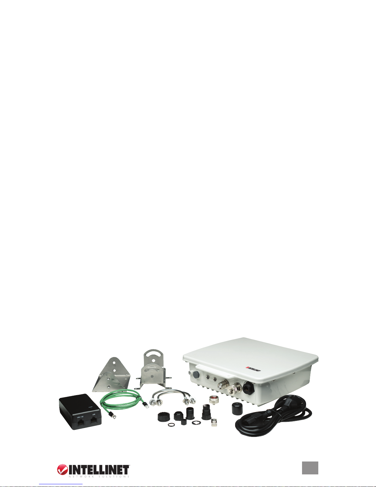
Package Contents
• Outdoor AP
• 48 V DC power adapter (PoE injector)
• Power cord
• Screws, washers and U-bolts
• Mounting brackets (for walls or pole mount)
• Grounding wire
• RJ45 waterproof plastic plug (IP67)
• CD-ROM (utility)
• User manual
3

TABLE OF CONTENTS
HARDWARE/CONNECTIONS ........................................................................6
BASIC IP NETWORKING ................................................................................7
CONFIGURATION ...........................................................................................8
Basic: Site Survey .....................................................................................8
Basic: Administration ................................................................................8
Basic: IP Conguration .............................................................................9
Basic: Operation Mode .............................................................................9
AP Repeater Mode .............................................................................10
Wireless Bridge Mode .........................................................................12
Advanced: Radio Setting ........................................................................13
Advanced: Security Setting ....................................................................14
WEP Security ......................................................................................14
WPA-PSK Security .............................................................................14
WPA Security ......................................................................................15
Advanced: MAC Access Control .............................................................15
Advanced: Protocol Filter ........................................................................15
Advanced: SNMP Conguration .............................................................16
Advanced: Miscellaneous .......................................................................16
Status: System Status .............................................................................17
Status: Association Status ......................................................................17
Super User: Super User ..........................................................................18
Super User: Firmware Updgrade ............................................................18
Super User: Firmware Version................................................................18
UTILITY INSTALLATION & OPERATION ......................................................19
Software Installation ...............................................................................19
Operation ................................................................................................19
SPECIFICATIONS..........................................................................................21
NOTE: Some screen images have been modied to t the format of this manual.
section page
4
CONTENTS

Regulatory Statements
This equipment has been tested and found to comply with the limits for a Class B
digital device, pursuant to Part 15 of the Federal Communications Commission
(FCC) Rules. These limits are designed to provide reasonable protection against
harmful interference in a residential installation. This equipment generates, uses
and can radiate radio frequency energy and, if not installed and used in accordance
with the instructions, may cause harmful interference to radio communications.
However, there is no guarantee that interference will not occur in a particular
installation. If this equipment does cause harmful interference to radio or television
reception, which can be determined by turning the equipment off and on, the user
is encouraged to try to correct the interference by one of the following measures:
• Reorient or relocate the receiving antenna.
• Increase the separation between the equipment and receiver.
• Connect the equipment into an outlet on a circuit different from that to which the
receiver is connected.
• Consult the dealer or an experienced radio/TV technician for help.
FCC Caution
Any changes or modications not expressly approved by the party responsible
for compliance could void the user’s authority to operate this equipment. This
device complies with Part 15 of the FCC Rules. Operation is subject to the
following two conditions: 1) This device may not cause harmful interference, and
2) This device must accept any interference received, including interference
that may cause undesired operation.
FCC Radiation Exposure Statement
This equipment complies with FCC radiation exposure limits set forth for an
uncontrolled environment. This equipment should be installed and operated with
a minimum distance of 20 cm (approximately 8 inches) between the radiator and
your body. This transmitter must not be co-located or operated in conjunction with
any other antenna or transmitter.
The availability of some specic channels and/or operational frequency bands
is country-dependent: Channels are rmware-programmed at the factory to match
the intended destination. The rmware setting is not accessible by the end user.
European Union Notice
This product complies with R&TTE Directive (1999/5/EC) and the following:
• EN 60950-1:2001+A11:2004 Product Safety
• EN 300 328 Technical requirement for radio equipment
• EN 301 489-1/-17 General EMC requirements for radio equipment
• EN 50385
5
REGULATORY STATEM ENTS
6
HARDWARE/CONNECTIONS
Model 503679
External
Antenna
Surge
Protector
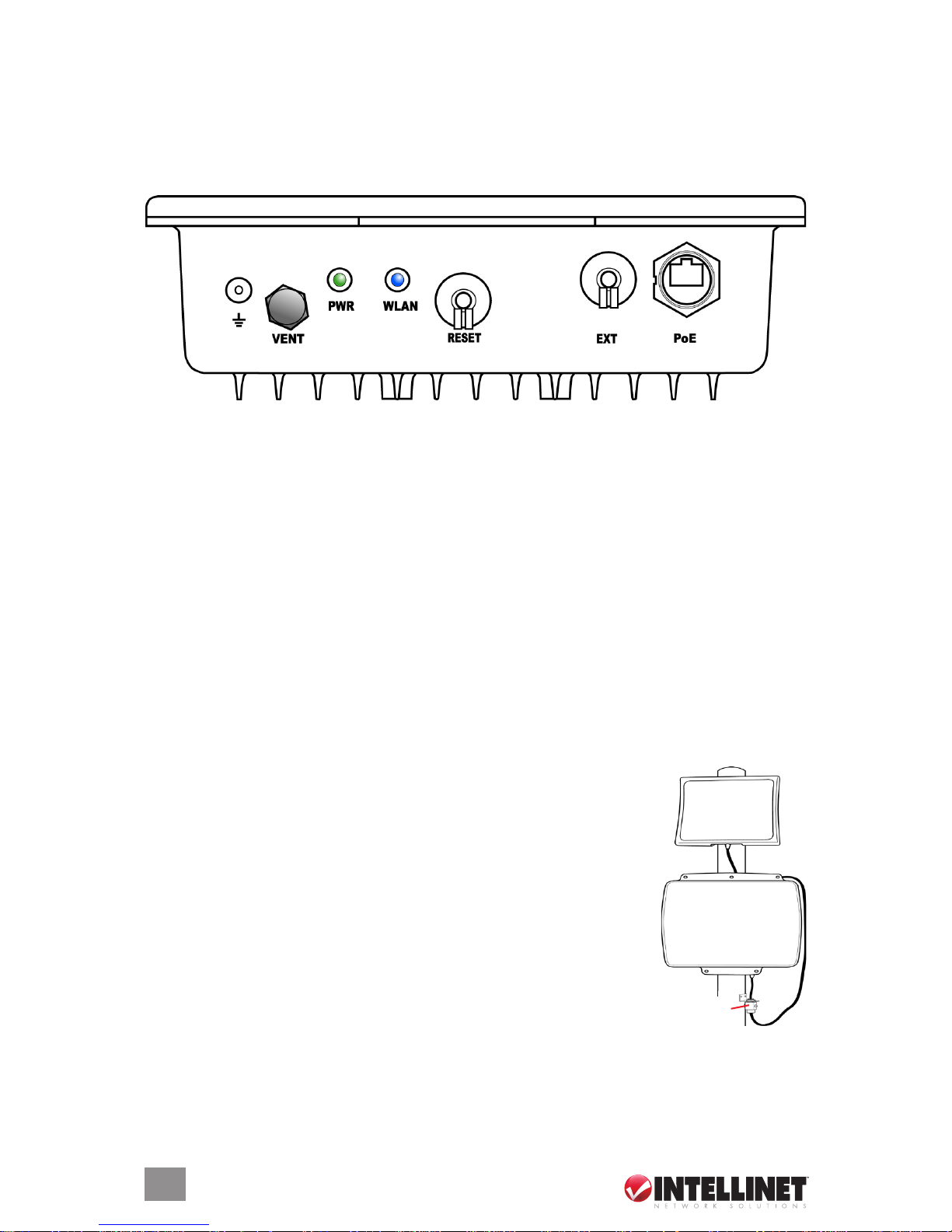
HARDWARE/CONNECTIONS
The components, connections and indicators depicted in the image (and directly
corresponding to the unit itself) are detailed below as they appear from left to right.
In addition, there are four holes on the rear panel of the device (the underside, as
shown here) for attaching either of the included mounting brackets.
Ground
Use the included ground wire to ground the device.
VENT
This special Gore membrane vent protects the device by allowing any water
moisture to escape while preventing excess moisture from entering. No
adjustments are necessary.
PWR
This LED lights green whenever the device is receiving power.
WLAN
This LED ashes blue during LAN activity.
RESET
To return any settings to factory defaults, unscrew the dust cap and press the
button for ve seconds or more.
EXT
If you require a higher-gain external antenna, unscrew the dust
cap and make your connection. The EXT connector features a
mechanical switch function that automatically disables the built-
in 9-dBi directional antenna and redirects the RF signal to the
external antenna. Conduct any signal alignment from the
external antenna. NOTE: Do not use the EXT connector for
any other purpose, as doing so could interfere with the
sophisticated mechanical switch inside the device. If the
cable used for an external antenna connection includes a
built-in surge protector, connect the shorter side of the cable to
the Wireless Super G Outdoor PoE Access Point and Bridge.
PoE
Unscrew the dust cap and connect the AP/bridge to the included PoE injector.

BASIC IP NETWORKING
IP (Internet Protocol)
IP stands for Internet protocol. In an IP network, every device has a unique IP
address (e.g., 192.168.10.35) to identify itself. There are two ways of assigning
an IP address to a PC or router: static and automatic (DHCP). Static IP addresses
are keyed in manually, while dynamic IPs are distributed by a DHCP server.
Ports
Every packet of trafc is identied by its source and destination addresses, which
ensures that the packet arrives at the correct destination. A port number is also
embedded in each packet to identify which software application generated and
uses that packet. If it blocks a certain port number, it prevents that particular
software from using the connection.
Static IP Address
Static IP addressing ensures that the device will always have the same IP address.
Static addressing is commonly used for your servers.
Dynamic IP Address
A dynamic IP address is one that is automatically assigned to a PC. These IP
addresses are “dynamic” because they are only temporarily leased to the PC
when it connects to the network. This is the most convenient and common way
of managing IP addresses in a network. The server that manages this pool of IP
addresses is called the DHCP server. This product has a DHCP server built in to
simplify the network management.
DHCP (Dynamic Host Conguration Protocol)
The PC obtaining an IP address from the server is called the DHCP client. If there
is already a DHCP server running on your network, you must disable one of the
two DHCP servers, as running more than one will cause network problems.
Wireless LAN
A wireless LAN (WLAN) is a computer network that transmits and receives data
using radio signals instead of cables. WLAN has become common in homes,
ofces, airports and public hotspots, and can support the same applications and
software that run on a wired network (LAN). It’s also more convenient, since it
eliminates the need to lay Ethernet cables in a home or ofce. WLAN networking
involves a few additional parameters that need to be congured:
SSID — The service set identier is the “network name” for the WLAN network,
and can be any set of characters or numbers. The DHCP client “sniffs” the
radio frequencies for an AP with the same SSID, then locks onto the AP (thus,
they’re “associated”). To enable Plug and Play convenience, most client cards
can sniff frequencies to extract available SSIDs for user selection.
Encryption — WLAN trafc can be captured by anybody to be read! The solution
is to use encryption to make the trafc appear as random characters to an
eavesdropper. Both the AP and client must use the same encryption standard
and key to enable them to decode the “rubbish.” If the encryption settings are
mismatched, the client and AP cannot associate. WEP (Wired Equivalent
Privacy) is the most common WLAN encryption standard.
Frequency — This device operates in the 2.4 GHz band. Depending on local
regulation, not all the frequencies may be available in every country. Frequency is
congured on the AP only: The client searches for the AP and locks onto that
AP’s channel.
7
BASIC IP NETWORKING
Signal Strength — Radio signals drop in power over distance, and even if all the
settings are correct, low signal strength makes association impossible. The
usable distance between the AP and client can range from a few meters
indoors to a few kilometers. When setting up the client, make sure that:
• The WLAN signals do not have to pass through too many concrete walls and
metal structures to reach the client.
• There is a line of sight between the AP and client device.
Interference — Interference happens when two clients with the same channels
are placed near one another. The speed of the network drops and the signal
strength uctuates.
Roaming — Association happens when the SSID, Encryption and MAC Address
Control settings are correct between the AP and client. If two APs with these
same settings are located in the same area, the client would choose to
associate to the one that gives it a better signal strength. The client would
“roam” over to the second AP when he moves nearer to it, switching AP and
frequency as he does so.
CONFIGURATION
Before conguring the Wireless Super G Outdoor PoE Access Point and Bridge,
check that the hardware connections have been properly made. If your PC is
wireless, check its card utility to make sure that the signal strength is good and
that the LEDs light up on the device.
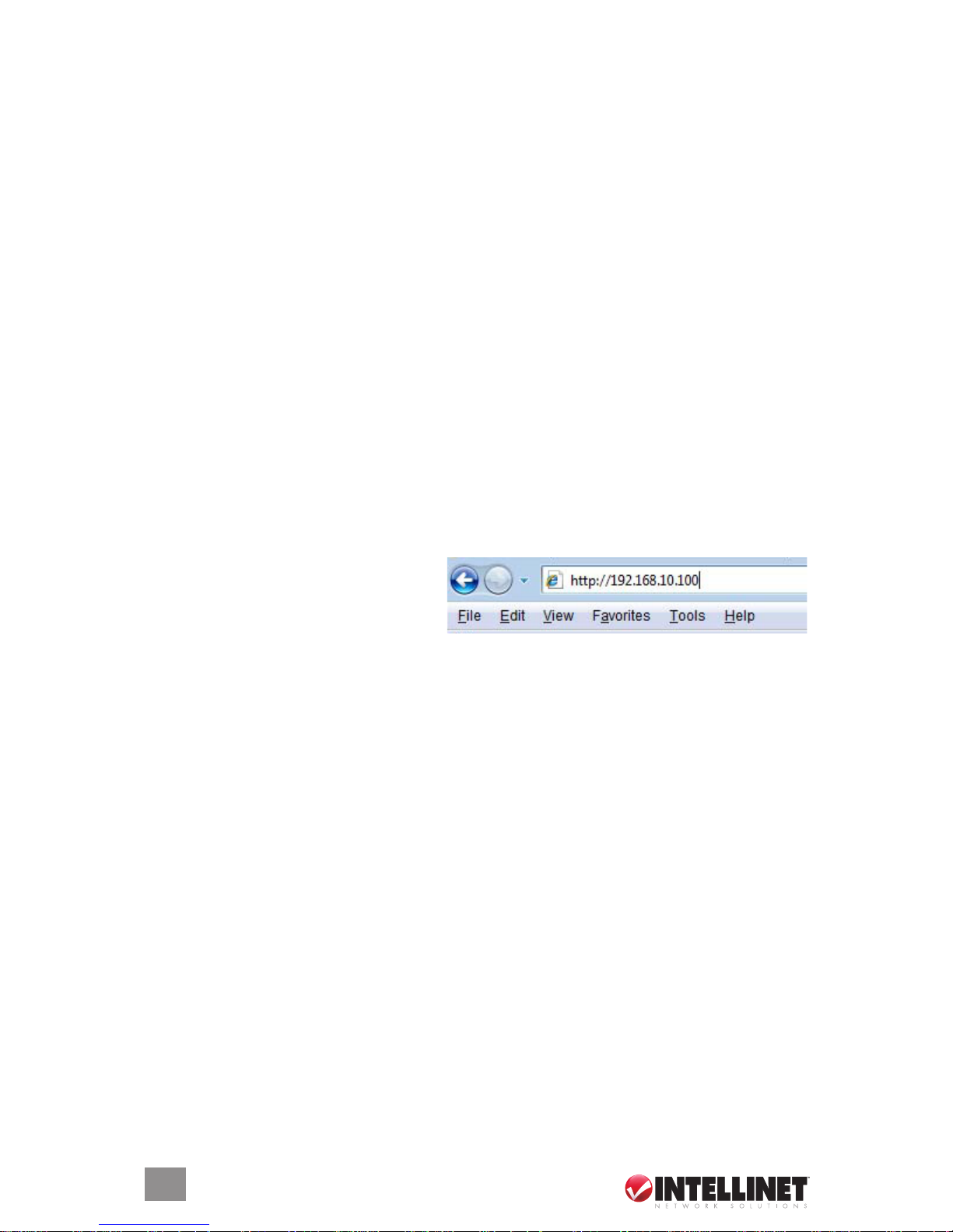
Open a Web browser and enter the
device’s LAN IP address in the
browser’s address eld. The default
address is 192.168.10.100.
The Conguration Menu’s left-hand-side navigation panel presents four main
sections — Basic, Advanced, Status and Super User — which are detailed
below along with each of their subsections.
Basic: Site Survey
This screen presents some of the current basic settings.
Basic: Administration
This screen allows you to change the username and password for admin user
and end user. Both defaults are “admin,” reverted to after every resetting to the
factory defaults. NOTE: Both the username and the password are case sensitive.
After making any changes, reboot the device for these changes to take effect.
8
CONFIGURATION
 Loading...