

Intellinet 503549, 503556, 503563 User Manual
DIN RaIl
PoweR
SuPPly
uSeR
maNual
MODELS 503549,
503556 & 503563
INT-503549/503556/503563-UM-0208-01
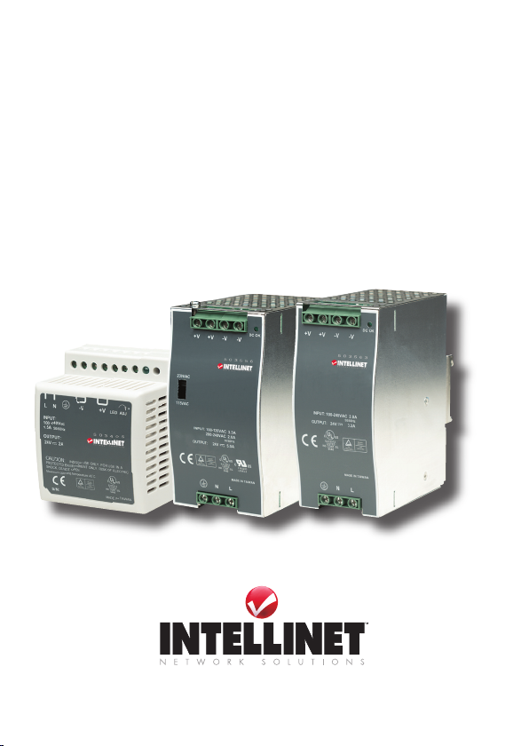
Thank you for purchasing the INTELLINET NETWORK SOLUTIONS™
DIN Rail Power Supply, Model 503549 (45 W / 2 A), Model 503563 (75
W / 3.2 A) or Model 503556 (120 W / 5 A).
This series of industrial power supplies provides reliable DC power for
any industrial Ethernet 24 V DC media converter or switch. Presenting
a rugged design, incorporating all international standards and approvals,
and offering short circuit, overload, over-voltage and over-temperature
protection, these high-quality power supplies have passed a 100%
full-load burn-in test and are UL/cUL listed, TUV/CB certied and CE
marked.
Easy-to-follow instructions in this user manual help make installation
of the switch quick and simple, so you’ll also soon be enjoying the
benets of these additional features:
• Universal AC input (85 – 264 V AC)
• DC-compatible input (120 – 370 V DC)
• Simple snap-on installation for TS35/7.5 or TS35/15 DIN rails
• Free-air cooling convection
• Built-in EMI lter and low ripple noise
• Lifetime Warranty
mouNtINg/INStallatIoN
Prior to installation, make sure that the power supply will be properly
ventilated for adequate heat dissipation.
• Do not cover the top or bottom surfaces of
the unit.
• When installing multiple units, leave enough
space between them for cooling.
• Forcing air over the unit(s) improves heat
dissipation.
Each of these DIN Rail Power Supply models
will attach to TS35/7.5 or TS35/15 DIN rails.
1. Insert the upper part of the DIN rail clip on the
power supply into the DIN rail track.
2
2. Pull down the plastic DIN rail lock beneath the clip and push the bottom
of the clip into the track.
3. Release the lock and check that the clip is securely positioned in the
track.
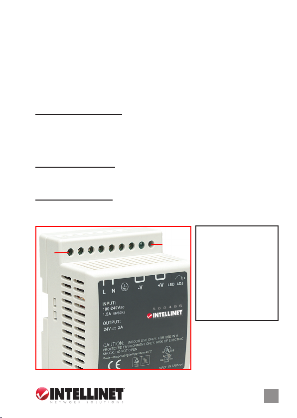
wIRINg/coNNectIoNS
Model 503549 (45 W / 2 A)
Connecting to DC Output: Insert the positive and negative wires into the
+V terminal contact (Pin 6 or 7) and –V terminal contact (Pin 4 or 5),
then tighten the terminal screws to prevent the wires from becoming
loose. NOTE: Always make sure that DC wiring is connected with the
correct polarity.
Connecting to AC Input: Insert the AC power lines into the Pin 1 and Pin 2
terminal contacts, then tighten the terminal screws to prevent the AC
wires from becoming loose.
Connecting to Ground: Connect the frame ground (Pin 3) of the power
supply to any nearby reliable ground with a thick wire to help ensure
safety and prevent system “noise.”
Pin No. Assignment
Pin 1
Pin 9
1 AC/ L
2 AC/ N
3 Ground
4/5 DC Output –V
6/7 DC Output +V
8 LED
9 +V Adj.
3
 Loading...