

Intellinet 503501, 503518, 503525 User Manual
INDUSTRIAL
GIGABIT
MANAGED
ETHERNET
SWITCH
USER
MANUAL
MODELS
503501,
503518,
503525
INT-503501/503518/503525-UM-0408-01
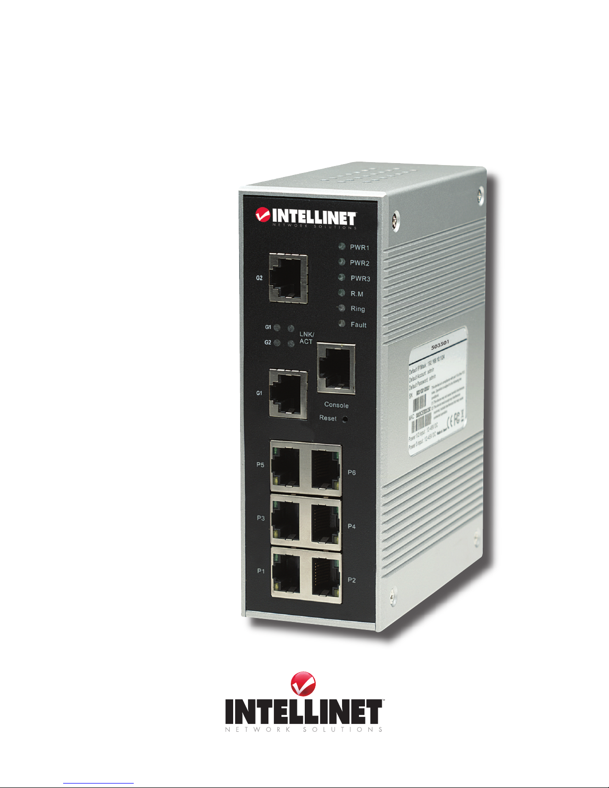
Model shown: 503501


INTRODUCTION
Thank you for purchasing the INTELLINET NETWORK SOLUTIONS™ Industrial Gigabit
Managed Ethernet Switch:
• Model 503501: 6-port 10/100Base-TX + 2-port 10/100/1000Base-TX, IP30 industrial standard
• Model 503518: 6-port 10/100Base-TX + 2-port 1000Base-LX (SC) Single-Mode, IP30
industrial standard
• Model 503525: 6-port 10/100Base-TX + 2-port 1000Base-SX (SC) Multi-Mode, IP30
industrial standard
Specically developed for industrial Ethernet applications, this series of switches uses a onepiece, formed-aluminum case to provide rugged, acid-corrosion-proof and heat-resistant
protection. The terminal block and ventilation holes are placed on the bottom side of each unit
to reduce the chance of damage due to dust and moisture. And the compact, space-saving
design is a benet throughout the product’s life — from inventory storage and transportation to
installation.
To meet industrial power-redundancy requirements, the Industrial Gigabit Managed Ethernet
Switch is equipped with dual DC power inputs and an AC-DC power adapter jack. Plus, a builtin relay contact can be used to set up a warning system for power failure. The relay output
function will form a short circuit when power fails, and will automatically form an open circuit
when port link or power input resumes. That way, the rail switch informs your maintenance
engineers of the problems, and you can take action to prevent network downtime.
The exible network management system is easy to use and manage, and it’s designed to
increase business productivity by reliably supporting business applications. It features a Web-
based GUI and supports SNMP, RMON, Port Mirroring, VLAN, QoS and more!
The detailed instructions in this user manual help make installation of the switch reasonably
quick and simple, so you’ll also soon be enjoying the benets of these additional features:
• Auto-sensing RJ-45 ports automatically detect optimal network speeds
• All RJ-45 ports with Auto MDI-X and NWay auto-negotiation support
• Supports SNMP V1, V2C, V3
• LACP Link Aggregation
• IGMP Snooping for multicast ltering
• GVRP VLAN Registration Protocol
• Supports per-port egress/ingress rate control
• Supports 802.1X EAP and RADIUS authentication
• Port security via MAC addresses
• DHCP Server, DHCP Client
• Supports 2,048 MAC address entries
• 128 kBytes buffer memory
• LEDs for power, link/activity, full/half duplex
• Provides true non-blocking switching performance
• Supports IEEE 802.3x ow control on full duplex and back pressure on half duplex
• Store-and-forward switching architecture
• Full/half duplex operation
• DIN rail kit, or wall-mounting ears for 3-way installation
• Terminal block to provide dual power inputs with reverse polarity protection
• Lifetime Warranty
NOTE: Some full and partial screen images have been modied to t the format of this user
manual.
3
INTRODUCTION

TABLE OF CONTENTS
HARDWARE ....................................................................................................5
DIN-Rail Installation ..................................................................................5
Wall-Mount Installation..............................................................................5
Front-Panel Ports & Indicators ..................................................................5
Bottom-Panel Connectors ........................................................................6
WEB MANAGEMENT & CONFIGURATION ...................................................6
Basic Settings ...........................................................................................7
Port Conguration .....................................................................................9
Redundancy ............................................................................................10
VLAN .......................................................................................................13
Trafc Prioritization .................................................................................14
IGMP Snooping .......................................................................................15
SNMP Conguration ...............................................................................16
Security ...................................................................................................17
Warning ...................................................................................................19
Monitoring .............................................................................................. 20
Save Conguration .................................................................................21
CLI MANAGEMENT & CONFIGURATION ....................................................21
CLI Command Sets ................................................................................ 23
APPENDIX A ................................................................................................. 35
SPECIFICATIONS ......................................................................................... 36
section page
4
CONTENTS
HARDWARE
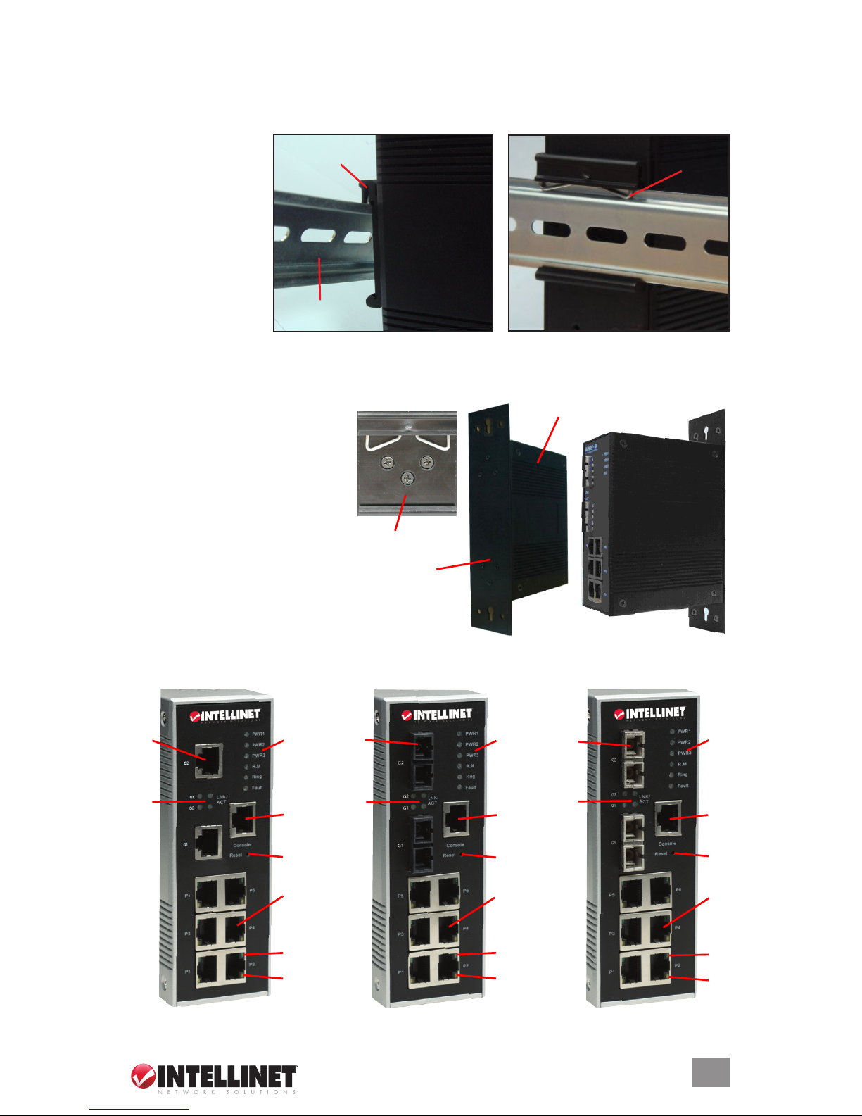
DIN-Rail Installation
1. Angle the switch’s
mounting clamp
relative to the DIN
rail (near right) so
that the DIN rail is
positioned under
the upper lip of the
clamp and behind
the metal springs.
2. Push the switch
toward the DIN rail
until the spring on the mounting clamp clicks in place on the rail (above right).
Wall-Mount Installation
1. Remove the DIN rail mounting
clamp from the back panel of
the switch.
2. Attach the wall-mount panel to
the switch using the six included
screws.
3. With the wall-mount panel
securely connected to the
back of the switch, attach
the switch to a wall or other
suitably sturdy vertical surface.
Front-Panel Ports & Indicators
DIN rail
Mounting
clamp
Switch
Spring
Wall-mount panel
Switch
Mounting clamp
5
HARDWARE
Model 503501
Model 503525
Model 503518
3 23
5
9
4
6
7
7
8
3
2
1
4
4
5 5
6
6
7
9
8
9
8
1 Gigabit Ethernet ports
2 Gigabit ber ports
3 LEDs for:
• PWR 1-3 (lighted indicates a power link to a DC power module [PWR 1 & 2] or the DC power
jack [PWR 3])
• R.M, or ring master (lighted indicates this unit is serving as the master switch in a ring)
• Ring (blinking slowly indicates the ring has only a single link; blinking rapidly indicates the
ring is activated and operating normally)
• Fault (lighted indicates a fault has occurred)
4 LEDs for Gigabit Ethernet/ber ports (lighted LNK indicates the port is linked; lighted ACT
indicates data is being transmitted)
5 Console port
6 Reset button (push in 3 seconds to reset the switch; 5 seconds to reset to factory defaults)
7 10/100Base-TX Ethernet ports
8 LEDs for Ethernet ports (lighted indicates the port is linked)
9 LEDs for Ethernet ports (lighted indicates the port is linked and operating in full duplex mode)
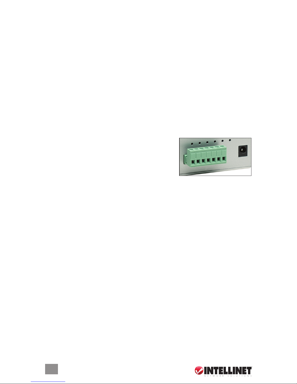
Bottom-Panel Connectors
The terminal block on the bottom of the switch — featuring
dual DC power inputs — and an AC/DC power adapter jack
are provided for power redundancy and reverse-polarity
protection. Connections (L-R): GND, V1+ and V1– (PWR 1),
Relay Output (1 A / 24 V DC), V2+ and V2– (PWR 2).
To the right of the block is the PWR 3 jack (12–45 V DC).
WEB MANAGEMENT & CONFIGURATION
Inside the CPU of the Industrial Gigabit Managed Ethernet Switch, an embedded HTML Web
site resides in ash memory. It contains advanced management features and allows you to
manage the switch from anywhere on the network through a standard browser, such as Microsoft
Internet Explorer. The Web-based management supports Internet Explorer 5.0 and is based on
Java Applets, with the intent of reducing network bandwidth consumption, enhancing access
speed and presenting an easy viewing screen. NOTE: By default, IE5.0 (or a later version) does
not allow Java Applets to open sockets. The browser setting needs to be explicitly modied in
order to enable Java Applets to use network ports.
Default Values
IP address: 192.168.10.1
Subnet mask: 255.255.255.0
Default gateway: 192.168.10.254
Username: admin
Password: admin
System Login Procedure
1. Launch Internet Explorer (IE).
2. In the Address eld of IE, enter http:// followed by the IP address of the switch. Press “Enter.”
3. When the login screen appears, enter the username and password (both “admin”) in their
respective elds.
4. Click “OK” to display the Main Interface screen of the Web-based management system.
GND V1+ V1– Relay V2+ V2–
12–48 V DC
power jack
6
WEB MANAGEMENT & CONFIGURATION
The Main Interface screen introduces the main menu in the form of a left-side navigation column,
with each section folder — Basic Settings, Port Conguration, Redundancy, VLAN and so on —
opening to present sub-categories (as listed throughout the rest of this manual) that provide
details and conguration options for that particular part of the Web-based management system.
Basic Settings
Switch Settings
System Name: You can assign a name for the switch here (max. 64 characters).
System Description: Displays a description of the switch.
System Location: You can identify the physical location of the switch here (max. 64 characters).
System Contact: Enter the name of a contact person or organization.
Firmware Version: Displays the switch’s rmware version.
Kernel Version: Displays the kernel software version.
MAC Address: Displays the unique hardware address assigned by the manufacturer (default).
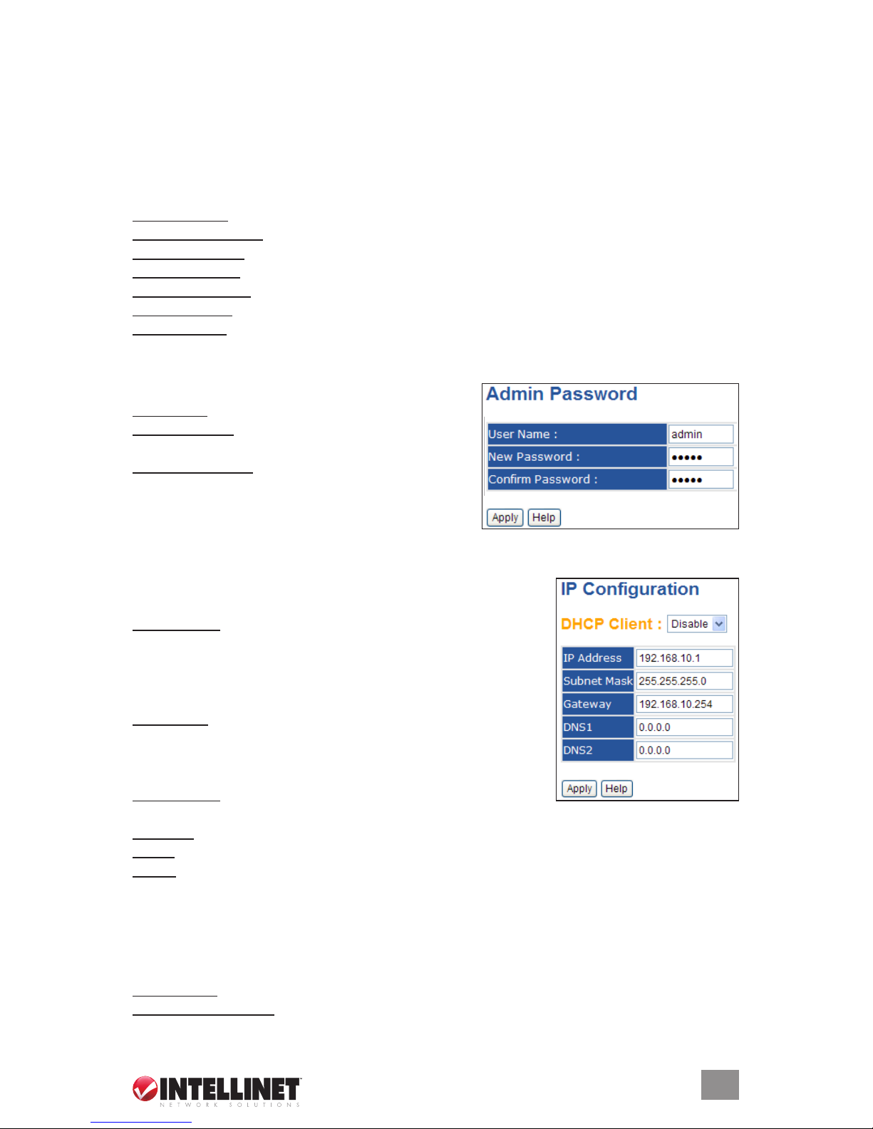
Admin Password
For added security, these elds let you make changes.
User Name: Enter a new username (default is “admin”).
New Password: Enter a new password (default is
“admin”).
Conrm Password: Re-enter the new password. As on
all screens where applicable, click “Apply” to effect
any changes made since the most recent screen
refresh or system/device reboot.
IP Conguration
On this screen, you can congure the IP settings and the DHCP
Client function.
DHCP Client: Enable or disable the DHCP Client function using
the drop-down menu. When the function’s enabled, the switch
will be assigned the IP address from the network DHCP server,
replacing the default IP address. After clicking “Apply,” a pop-up
window displays to declare when DHCP Client is enabling.
IP Address: Assign the IP address the network is using. If DHCP
Client is enabled, it’s not necessary to assign the IP address:
The network DHCP server will assign the IP address for the
switch and display it. The default IP is 192.168.10.1.
Subnet Mask: Assign the subnet mask of the IP address. If DHCP
Client is enabled, you do not need to assign the subnet mask.
Gateway: Assign the network gateway for the switch. The default gateway is 192.168.10.254.
DNS1: Assign the primary DNS IP address.
DNS2: Assign the secondary DNS IP address.
Click “Apply” to effect any changes.
SNTP Conguration
On this screen, the SNTP (Simple Network Time Protocol) settings allow you to synchronize
clocks within your network/system.
SNTP Client: Enable or disable the SNTP function to get the time from the SNTP server.
Daylight Saving Time: Enable or disable the Daylight Saving Time (DST) function. When DST
is enabled, the DST period needs to be congured.
7
WEB MANAGEMENT & CONFIGURATION
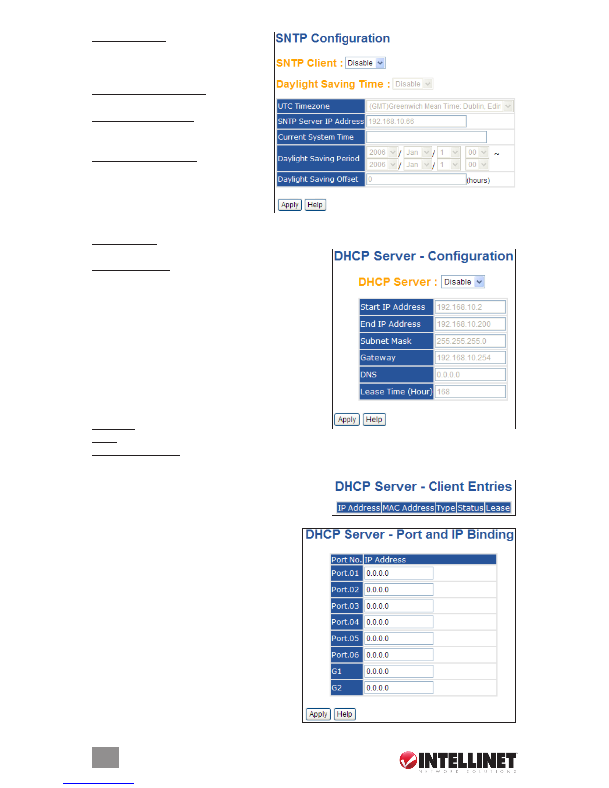
UTC Time Zone: Set the switch’s local
time zone. Appendix A at the back of
this manual lists the various local
time zones for your reference.
SNTP Server IP Address: Set the SNTP
server IP address.
Daylight Saving Period: Set the DST
beginning and ending dates. NOTE:
Both change each year.
Daylight Saving Offset: Set the offset
time.
Click “Apply” to effect any changes.
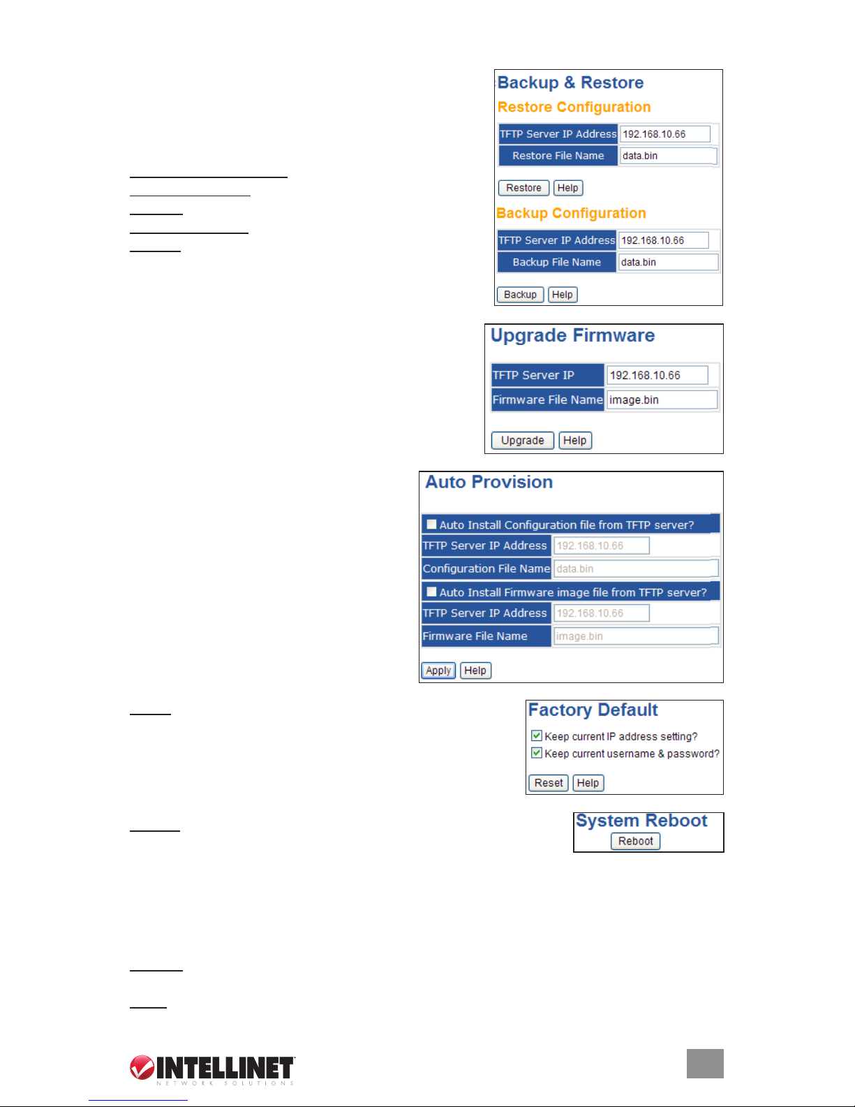
DHCP Server
By enabling the DHCP Server function, the switch system will become a DHCP server.
DHCP Server: Enable or disable the DHCP Server function. By enabling the switch, it becomes
the DHCP server on your local network.
Start IP Address: In a dynamic IP assigned range,
the low IP address is the beginning of the dynamic
IP assigned range. For example: If the dynamic IP
assigned range is 192.168.1.100 to 192.168.1.200,
then 192.168.1.100 will be the Start IP Address.
End IP Address: In a dynamic IP assigned range,
the high IP address is the end of the dynamic IP
assigned range. For example: If the dynamic IP
assigned range is 192.168.1.100 to 192.168.1.200,
then 192.168.1.200 will be the End IP Address.
Subnet Mask: This is the dynamic IP assigned range
subnet mask.
Gateway: This is the gateway in your network.
DNS: This is the Domain Name Server IP address in your network.
Lease Time (Hour): This is the point at which the system will reset the assigned dynamic IP to
ensure the IP address is in use.
Client Entries — When the DHCP Server function
is activated (“Enable”), the system will collect the
DHCP client information and display it here.
Port and IP Bindings — You can assign the
specic IP address that’s in the assigned
dynamic IP range to a specic port. When the
device is connecting to the port and asks for
dynamic IP assigning, the system will assign
the IP address that has been assigned before
in the connected device.
Click “Apply” to effect any changes.
8
WEB MANAGEMENT & CONFIGURATION
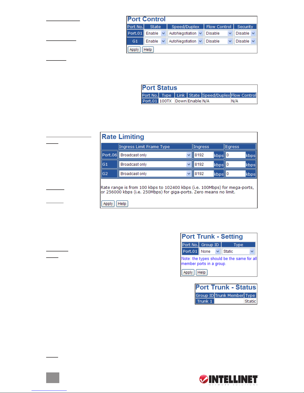
Backup & Restore
You can save current EEPROM (electrically erasable
programmable read-only memory) values from the switch
to the TFTP (Trivial File Transfer Protocol) server, then
go to the TFTP restore conguration page to restore the
EEPROM values.
TFTP Server IP Address: Enter the address.
Restore File Name: Enter the le name.
Restore: Click to restore the conguration.
Backup File Name: Enter the le name.
Backup: Click to back up the conguration.
Upgrade Firmware
This screen allows you to update the switch rmware.
Before updating, make sure that you have your TFTP
(Trivial File Transfer Protocol) server ready and that the
rmware image is on the TFTP server.
Auto Provision
This screen allows you to update the switch
rmware automatically. You can put the
rmware or a conguration le on the TFTP
(Trivial File Transfer Protocol) server and,
when you reboot the switch, it will upgrade
automatically. Before updating, make sure
that you have your TFTP server ready and
that the rmware image and conguration
le are on the TFTP server. Click “Apply” to
effect any changes.
Factory Default
Reset: Click to reset all congurations to the default values.
NOTE: Select “Keep current IP address setting?” and “Keep
current username & password?” to prevent these values from
reverting to factory defaults.
System Reboot
Reboot: Click to restart the switch.
Port Conguration
Port Control
This screen presents conguration options for the state, speed/duplex, ow control and security
of each port.
Port No: Identies each port: 1–6 represent the 10/100Base-TX Ethernet ports; G1–2 represent
the Gigabit Ethernet ports.
State: Enable or disable the port.
9
WEB MANAGEMENT & CONFIGURATION
Speed/Duplex: Set the mode to
“Auto-Negotiation,” “100 Full,”
“100 Half,” “10 Full” or “10 Half.”
Flow Control: Enable or disable.
Choose “Enable” to avoid packet
loss when trafc is congested.
Security: Enable or disable port security.
Click “Apply” to effect any changes.
Port Status
This screen presents the current settings
established for each port in Port Control,
plus the current status of port activity.
Rate Limiting
This screen lets you limit trafc on all ports, including broadcast, multicast and ooded unicast.
You can also set parameters for Ingress or Egress to limit trafc received or transmitted.
Ingress Limit Frame
Type: Mode options in
the drop-down menu
are “All,” “Broadcast
only,” ”Broadcast/
Multicast” and
“Broadcast/Multicast/
Flooded Unicast.”
Ingress: Received
trafc speed.
Egress: Transmitted
trafc speed.
Click “Apply” to effect any changes.
Port Trunk
Setting — This screen allows you to establish a port trunk
by designating Ports 1–6 (only Port 1 shown) and/or G1–2.
Group ID: Select a port to join to a trunk group.
Type: Options are “Static” or “802.3ad LACP (Link
Aggregation Control Protocol)” to increase bandwidth by
combining several physical ports into a logical link.
Click “Apply” to effect any changes.
Status — This screen simply presents the current status of any
port trunk conguration(s) established in Port Trunk – Setting
(above), with up to four trunks possible.
Redundancy
Ring
With a recovery time of less than 10 ms, the Ring feature is able to reduce damage caused by
unexpected network topology changes. The Ring function presents three application options:
Ring, Coupling Ring and Dual Homing.
Ring: Select to enable.
10
WEB MANAGEMENT & CONFIGURATION
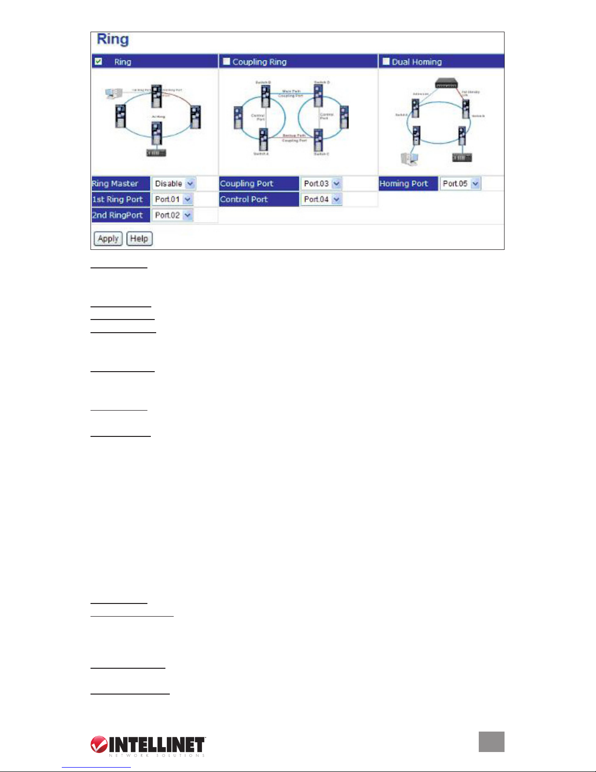
Ring Master: There should be one and only one ring master in a ring. However, if there are two
or more switches that have Ring Master set to “Enable,” the switch with the lowest MAC address
will be the actual ring master and others will serve as backup masters.
1st Ring Port: This is the primary port when this switch is the ring master.
2nd Ring Port: This is the backup port when this switch is the ring master.
Coupling Ring: Select to enable. Coupling Ring can be used to divide a big ring into two smaller
rings to avoid affecting all switches when network topology changes. It’s a good application
for connecting two rings.
Coupling Port: Link to the coupling port of the switch in another ring. The Coupling Ring feature
needs four switches to build an active and a backup link. Designate a port as a coupling port:
The coupled four ports of four switches will operate in active/backup mode.
Control Port: Link to the control port of the switch in the same ring. A control port is used to
transmit control signals.
Dual Homing: Select to enable, which connects the ring to normal switches through two RSTP
links (like a backbone switch). The two links work as an active/backup mode, and connect
each ring to the normal switches in RSTP mode.
NOTE: It’s recommended that you don’t set a single switch as both a ring master and a coupling
ring due to the heavy load.
Click “Apply” to effect any changes.
RSTP
The Rapid Spanning Tree Protocol (RSTP) evolved from the Spanning Tree Protocol, providing
faster spanning tree convergence after a topology change. The system supports STP, and will
auto-detect the connected device that is running the STP or RSTP protocol.
Setting — On this screen, enable/disable the RSTP function and set parameters for each port.
RSTP Mode: RSTP needs to be enabled or disabled before conguring the related parameters.
Priority (0–61440): This is a value used to identify the root bridge. The bridge with the lowest
value has the highest priority and is selected as the root. If the value changes, the switch
needs to be re-booted. NOTE: The value must be a multiple of 4,096 according to the
protocol standard rule.
Max Age (6–40): This is the number of seconds a bridge waits without receiving any STP
conguration messages before attempting a reconguration. Enter a value from 6 to 40.
Hello Time (1–10): This is the time that controls when the switch sends out a BPDU packet to
check the RSTP current status. Enter a value from 1 to 10.
11
WEB MANAGEMENT & CONFIGURATION
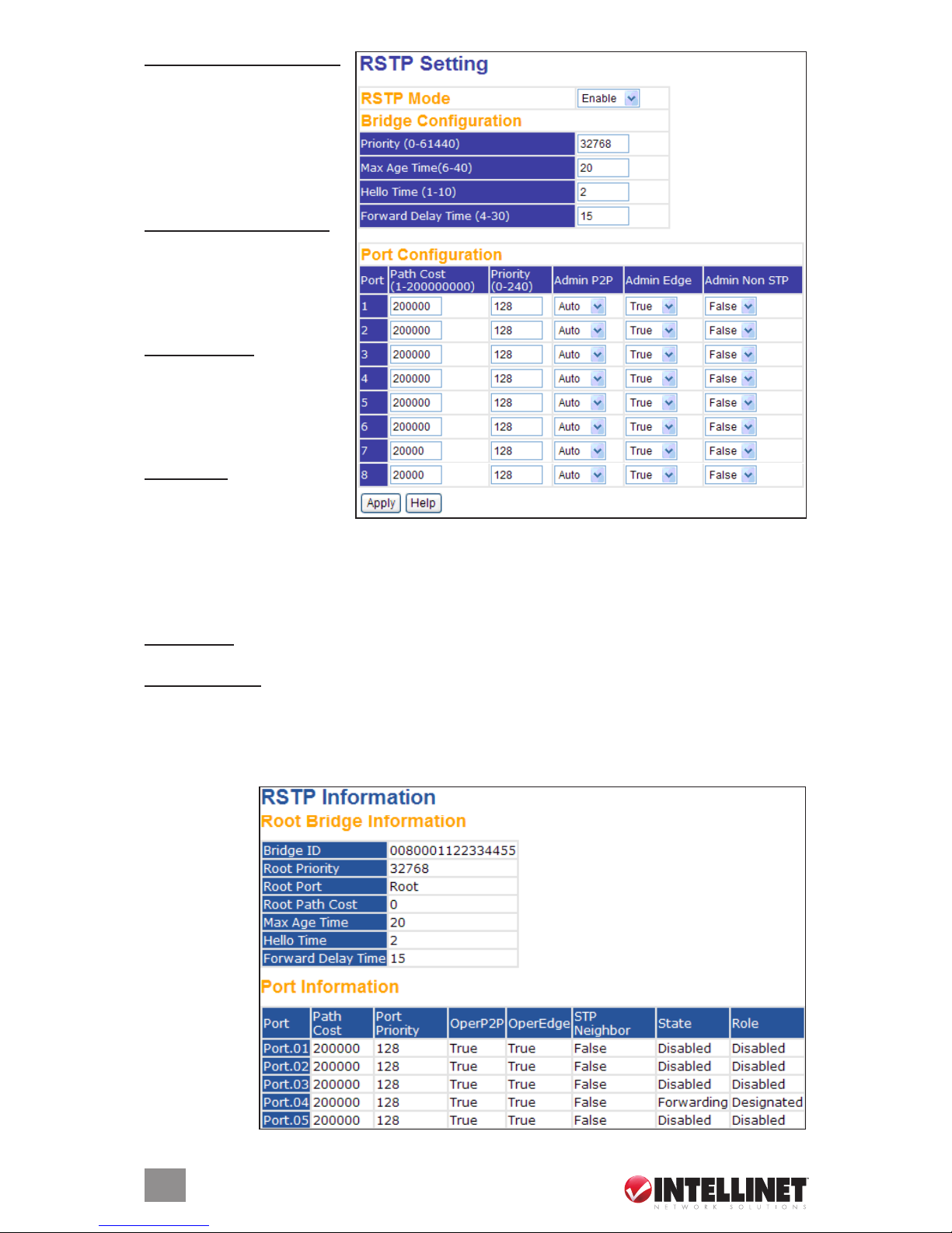
Forward Delay Time (4–30):
This is the amount of time
a port waits before changing
from its Rapid Spanning
Tree Protocol learning and
listening states to the
forwarding state. Enter a
value from 4 to 30.
Path Cost (1–200000000):
This is the cost of the path
to the other bridge from
this transmitting bridge at
the specied port. Enter a
number 1 to 200000000.
Priority (0–240): Decide which
port should be blocked by
priority in LAN, and enter a
number up to 240. NOTE:
The value of priority must
be a multiple of 16.
Admin P2P: Some of the
rapid-state transactions
that are possible within
RSTP depend on whether 1) the port concerned can only be connected to exactly one other
bridge (i.e., it’s served by a point-to-point LAN segment), or 2) it can be connected to two or
more bridges (i.e., it’s served by a shared medium LAN segment). This function allows the
P2P status of the link to be manipulated administratively. “True” means P2P enabling; “False”
means P2P disabling; “Auto” is the third option.
Admin Edge: This determines if a port is directly connected to end stations; if so, it can’t create
a bridging loop in the network. To congure the port as an edge port, set the port to “True.”
Admin Non STP: This indicates whether or not the port includes the STP mathematic calculation.
“True” doesn’t include the STP mathematic calculation; “False” does.
NOTE: Use this rule to congure Max Age, Hello Time and Forward Delay Time:
2 x (Forward Delay Time value –1) ≥ Max Age value ≥ 2 x (Hello Time value +1)
Click “Apply” to set the congurations or effect any changes.
Information —
This screen
displays current
RSTP root
bridge and port
congurations
and settings.
12
WEB MANAGEMENT & CONFIGURATION
 Loading...