

Intellinet 502931 Instructions Manual
8-PORT
POE MIDSPAN
INSTRUCTIONS
M O D E L 5 0 2 9 31
intellinetnetwork.com
Important: Read before use. • Importante: Leer antes de usar.
INT-502931-UM-ML1-1214-02
8-Port PoE Midspan • User Manual English
Thank you for purchasing the Intellinet Network Solutions 8-Port PoE
Midspan, Model 502931. For a full list of specications, refer to the
datasheet available at intellinetnetwork.com.
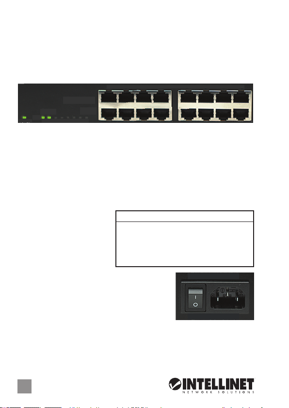
CONNECTIONS & INDICATORS
1 2 3 4 5 6 7 8
POWER + DATA (OUT)
PD LINK
1 2 3 4 5 6 7 8
POWER
Ports
The lower row of RJ45 ports — Data (In) — on the front panel delivers data
to the Midspan from existing network devices. The upper row of RJ45 ports
— Power + Data (Out) — delivers data while also powering added devices
(up to 15.4 watts per port). Use standard Cat5 or better Ethernet cables for
connections to PoE-supported IP cameras, wireless access points, other
switches, etc. NOTE: Powered devices should also comply with IEEE 802.3af.
LEDs
If an LED doesn’t light to
indicate a link or activity,
check the corresponding
device for proper setup and
operation.
Power
On the rear panel, plug in the included power
cord and connect the switch to an AC outlet.
Toggle the Power switch to On and conrm that
the Power LED is lit.
RACK MOUNTING
Simply align the two brackets with the holes on each side panel and secure
them with the included screws. Use the remaining screws to mount the
device in a rack.
DATA (IN)
LED Status Operation
POWER On Power on
O Check the AC connection; power on
PD Link On Port is linked and providing 48 V to a
(1-8) powered device
O No link is established
ON
OFF
2
ENGLISH
PoE Midspan • Handbuch Deutsch
Vielen Dank für den Kauf des Intellinet Network Solutions 8-Port PoE
Midspan, Modell 502931. Ein Datenblatt mit der vollständigen Liste aller
Spezikationen nden Sie auf intellinetnetwork.com.
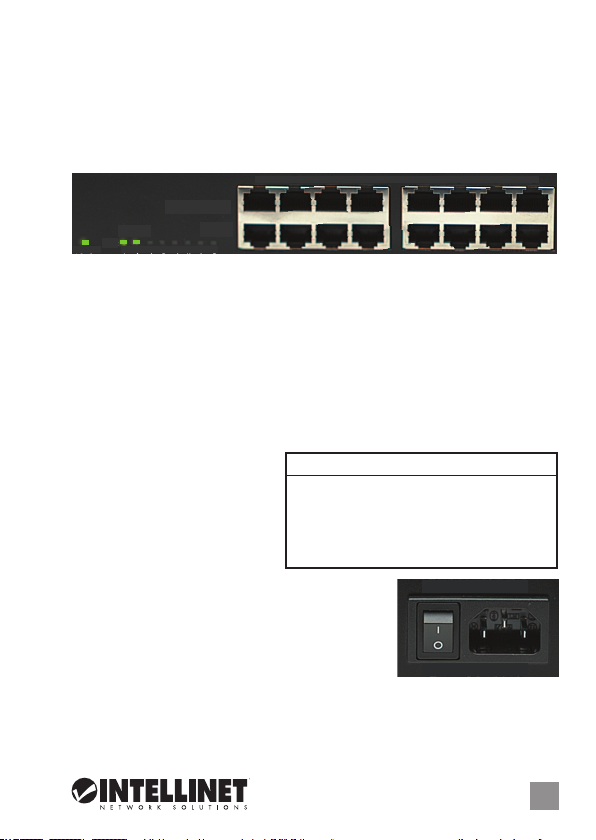
ANSCHLÜSSE & ANZEIGEN
1 2 3 4 5 6 7 8
POWER + DATA (OUT)
PD LINK
1 2 3 4 5 6 7 8
POWER
Ports
Die untere Reihe der RJ45-Ports — Daten (Eingang) — an der Vorderseite liefert
Daten der vorhandenen Netzwerkgeräte an den Midspan. Die obere Reihe der
RJ45-Ports — Strom + Daten (Ausgang) — liefert Daten und versorgt angeschlossene
Geräte gleichzeitig mit Strom (bis zu 15,4 Watt pro Port). Verwenden Sie Standard
-Cat5- oder bessere Ethernet-Kabel für den Anschluss von IP-Kameras mit PoEUnterstützung, Wireless Access Points, anderen Switchen, etc. HINWEIS: Mit
Strom versorgte Geräte sollten außerdem mit IEEE 802.3af kompatibel sein.
LED-Anzeigen
Sollte eine LED-Anzeige von
Verbindung oder Aktivität nicht
leuchten, prüfen Sie das
entsprechende Gerät auf korrekte
Einrichtung und Betrieb.
Strom
Schließen Sie das beiliegende Stromkabel auf der
Rückseite des Geräts und an einer Steckdose an.
Stellen Sie den Netzschalter auf Ein und prüfen Sie,
ob die “Power”-LED leuchtet.
RACKMONTAGE
Bringen Sie die beiden Befestigungswinkel auf Höhe der Löcher an den Seiten
an und xieren Sie sie mit den beiliegenden Schrauben. Verwenden Sie die
restlichen Schrauben, um das Gerät am Rack zu befestigen.
DATA (IN)
LED Status Bedeutung
POWER An Gerät wird mit Strom versorgt
Aus Prüfen Sie die Steckdosenverbindung
PD Link An Port ist verbunden und liefert 48 V an
(1-8) angeschlossenes Gerät
Aus Keine Verbindung hergestellt
ON
OFF
DEUTSCH
3
Midspan PoE • Manual del usuario Español
Gracias por comprar el Midspan PoE de 8 puertos Intellinet Network Solutions,
Modelo 502931. Para obtener una lista completa de especicaciones, consulte intellinetnetwork.com.
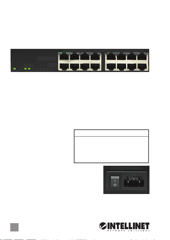
CONNECTIONS & INDICATORS
1 2 3 4 5 6 7 8
POWER + DATA (OUT)
PD LINK
1 2 3 4 5 6 7 8
POWER
Puertos
La la inferior de los puertos RJ45 — Datos (IN) — en el panel frontal recibe
datos de lso dispositivos de red existentes. La la superior de los puertos
RJ45 — Power + Data (Out) — entrega datos y al mismo tiempo alimenta
dispositivos (hasta 15,4 watts por puerto). Use cables estandard Cat5 o
superiores para conexiones PoE soportando cameras IP, Access Point
inalambricos, otros switches, etc. NOTA: Los dispositivos energizados deben
cumplir con IEEE 802.3af.
LEDs
Si un LED no enciende indica un
vinculo ó actividad, revise el
dispositivo correspondiente para
ajustar su conguracion y
operación.
Encendido
En el panel trasero, conecte el cable de corriente
incluido al switch y otro extremo a una toma de AC.
Mueva el switch de encendido para encender y
conrme que el LED de power está encendido.
MONTAJE EN RACK
Simplemente alinee los dos soportes con los agujeros en cada panel lateral
y jelos con los tornillos incluidos. Use los tornillos restantes para montar el
dispositivo en el rack.
DATA (IN)
LED Status Operación
POWER Encendido Encendido
Apgado Compruebe la conexion CA
PD Link Encendido Puerto esta vinculado y provee
(1-8) 48 V de energia por dispositivo
Apagado Sin comunicación
ON
OFF
4
ESPAÑOL
 Loading...