

Page 1
INT-176224/176231-UM-0207-02
Network Camera
outdoor eNClosure
user maNual
MODELS 176224
& 176231
Model 176224
Model 176231
Page 2

2
Thank you for purchasing the INTELLINET NETWORK SOLUTIONS™ Network Camera Outdoor
Enclosure, Model 176224 or Model 176231.
This weatherproof, aluminum enclosure protects INTELLINET NETWORK SOLUTIONS Pro Series
Network Cameras for outdoor use, featuring an integrated heating element and fan for severe
conditions; IP66-rated, dust-tight protection against heavy seas; a Cable Manager mounting
bracket through which the cables run for additional protection (Model 176224 only); and, of
course, the incomparable INTELLINET NETWORK SOLUTIONS Lifetime Warranty.
CAUTION: Any electrical connections should be made and/or serviced only by a qualified
electrician/technician. Never handle exposed electrical wiring without first disconnecting it from
the power source.
Page 3
3
iNstallatioN
Follow these steps for easy installation and reliable operation.
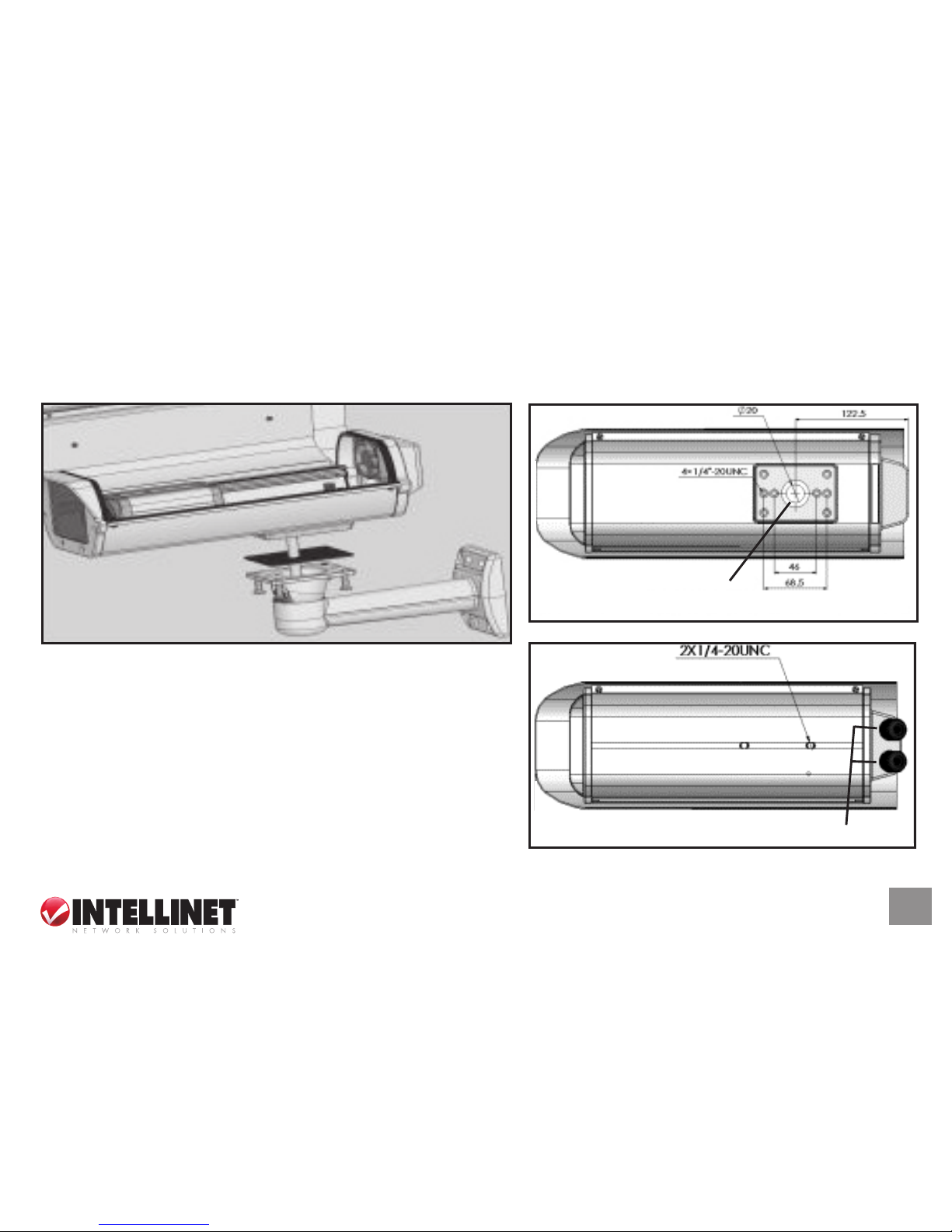
1. For Model 176224, shown above and at top
right (depicting the underside), fix the enclosure to
the Cable Manager mounting bracket (through
which the cable will run).
For Model 176231, with the underside depicted
at right, fix the enclosure to the mounting bracket.
Note the two rear outlets for the cable, which runs
outside the bracket.
Model 176231 cable outlets
Model 176224 cable outlet
(cable runs through bracket)
Page 4

4
2. Loosen the screws on the side of the
enclosure and open the cover.
3. Remove the camera setup base and affix it to
the camera. Place the camera and base back
in the housing and tighten the screws to hold
both securely in position.
Setup base
Camera
Page 5

5
4. Run the electrical wire from the power
source through the cable inlet (through
the Cable Manager mounting bracket
on Model 176224), then connect it to
the circuit board’s power input
connector.
5. Close and secure the cover by tightening the
screws on the side. Attach the entire unit to the
surface desired, then make final adjustments to
properly aim the camera.
GROUND
BLOWER OUTPUT
HEATER OUTPUT
CAUTION: Any electrical connections should be made and/or serviced only by a qualified
electrician/technician.
Never handle exposed electrical wiring without first disconnecting it from the power source.
Page 6

6
speCifiCatioNs
Standards
• IP66 (Ingress Protection)
General
• Heater activation temperature: 15°C (59°F)
• Heater deactivation temperature: 25°C (77°F)
• Fan activation temperature: 35°C (95°F)
• Fan deactivation temperature: 25°C (77°F)
• Window size: 70 x 70 mm (2.7 x 2.7 in.)
• Certifications: CE Mark, RoHS
Environmental
• Aluminum housing
• Housing dimensions: 140 (W) x 112 (H) x 400 (L) mm (5.5 x 4.4 x 15.7 in.)
• Weight: 1.5 kg (3.3 lbs.)
• Bracket dimensions, Model 176224 (Cable Manager):
95 (W) x 150 (H) x 260 (L) mm (3.7 x 5.9 x 10.2 in.)
• Bracket dimensions, Model 176231: 85 (W) x 150 (H) x 280 (L) mm (3.3 x 5.9 x 11 in.)
Page 7

7
Power
• 240 V AC, 50 Hz (U.S. version: 110 V AC, 60 Hz)
Package Contents
• Network Camera Outdoor Enclosure
• Mounting bracket (Cable Manager version for Model 176224)
• Mounting hardware
• User manual
Page 8

INTELLINET NETWORK SOLUTIONS™ offers a complete line of active and passive
networking products. Ask your local computer dealer for more information or visit
www.intellinet-network.com.
Copyright © INTELLINET NETWORK
SOLUTIONS
All products mentioned are trademarks or registered trademarks of their respective owners.
 Loading...