

Intellimix Yellowtec User Manual

Manual 2.21
INTELLIMIX® Manual 2.21 Yellowtec 2002 Page 1

1 BRIEF DESCRIPTION......................................................................................... 6
2
PRIOR TO BEGINNING ...................................................................................... 7
2.1 Manual conventions.......................................................................................... 7
2.1.1 Using the screen.................................................................................................................... 7
2.1.2 Printout...................................................................................................................................7
2.2 Unpacking......................................................................................................... 8
2.3 Scope of delivery .............................................................................................. 8
2.4 Safety instructions ............................................................................................ 9
GETTING STARTED WITH INTELLIMIX®........................................................ 10
3
3.1 Electrical connection....................................................................................... 10
3.2 Activation / Standby mode.............................................................................. 10
3.3 Preparation for the first operation ................................................................... 11
3.4 First operation................................................................................................. 12
3.5 Starting the configuration software quickly ..................................................... 14
3.5.1 Connection to the computer................................................................................................. 14
3.5.2 Installing the software .......................................................................................................... 15
3.5.2.1 Installing the CD-ROM ............................................................................................................... 15
3.5.2.2 Installation as an update ............................................................................................................ 15
3.5.3 First steps ............................................................................................................................16
4
CONTROL UNIT ................................................................................................ 18
4.1 Fader .............................................................................................................. 18
4.2 Fader Start indicator ....................................................................................... 18
4.3 Source Selector / PFL..................................................................................... 19
4.4 Level indicator................................................................................................. 19
4.5 Source/Status display..................................................................................... 19
4.6 Attention indicator........................................................................................... 20
4.7 Out Of Phase indicator ................................................................................... 20
4.8 Monitor Control ............................................................................................... 20
4.9 Monitor Source display ................................................................................... 20
4.10 Speaker/Headphone indicator.................................................................... 20
INTELLIMIX® Manual 2.21 Yellowtec 2002 Page 2

5 BASE UNIT........................................................................................................ 21
5.1 Front panel...................................................................................................... 21
5.2 Back panel...................................................................................................... 22
5.2.1 Power supply .......................................................................................................................22
5.2.2 Inputs/Outputs .....................................................................................................................22
5.3 Technical data ................................................................................................ 23
5.4 Information on the connections....................................................................... 24
5.4.1 Trigger outputs (GPOs) ....................................................................................................... 24
5.4.2 Trigger inputs (GPIs) ...........................................................................................................24
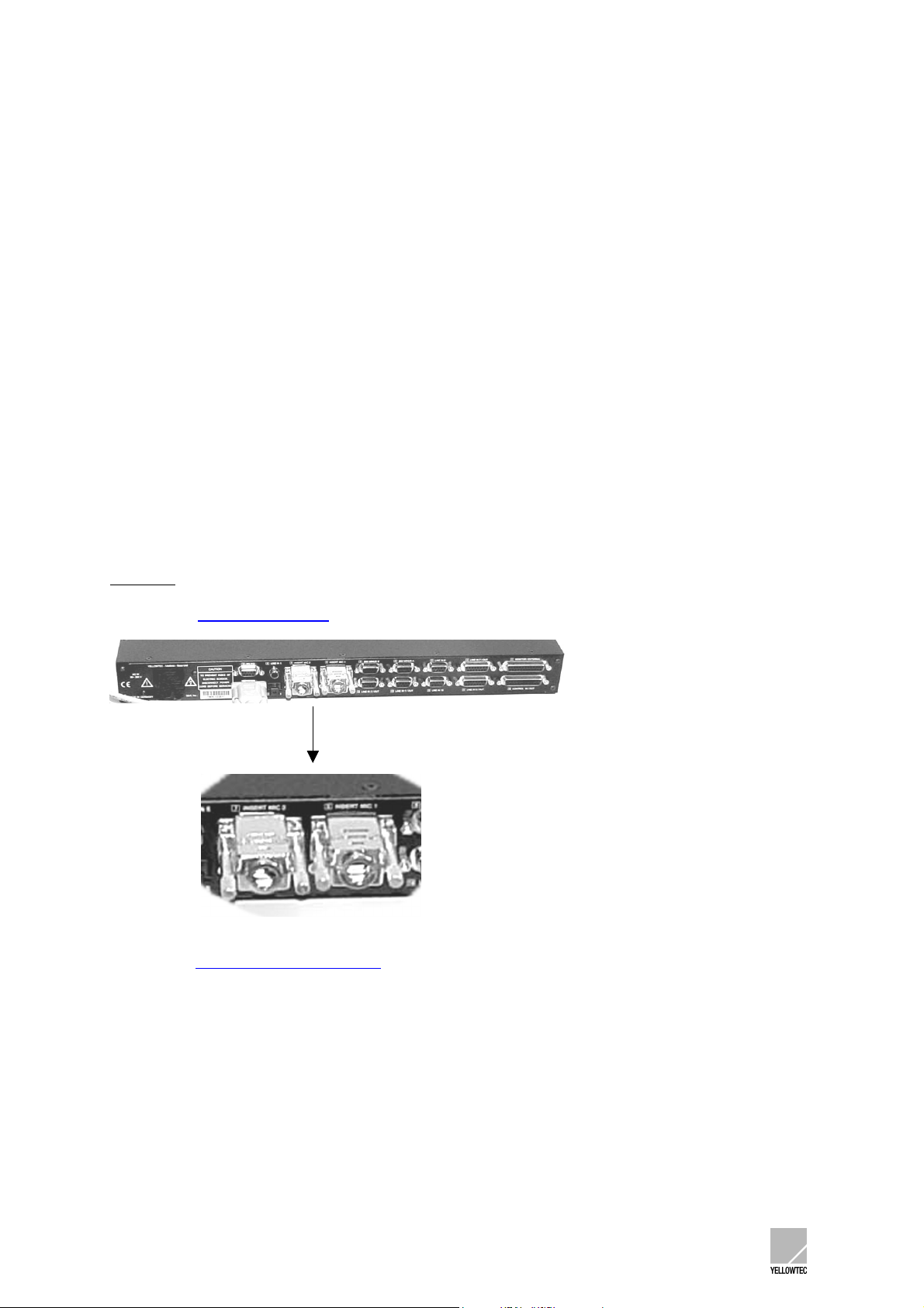
5.4.3 Microphone inserts ..............................................................................................................24
6
SOFTWARE....................................................................................................... 25
6.1 Program start.................................................................................................. 25
6.2 Menu: File....................................................................................................... 26
6.2.1 Submenu: New ....................................................................................................................26
6.2.2 Submenu: Open...................................................................................................................26
6.2.3 Submenu: Save ...................................................................................................................26
6.2.4 Submenu: Save as ..............................................................................................................26
6.2.5 Submenu: Change Password ..............................................................................................27
6.2.6 Submenu: Exit .....................................................................................................................27
6.3 Menu: Unit ...................................................................................................... 28
6.3.1 Note ..................................................................................................................................... 28
6.3.2 Submenu: Save to Unit........................................................................................................ 28
6.3.3 Submenu: Load from Unit.................................................................................................... 28
6.3.4 Submenu: Save to SmartCard............................................................................................. 28
6.3.5 Submenu: Load from SmartCard......................................................................................... 28
6.4 Menu: Firmware Update ................................................................................. 29
6.4.1 Note 1 ..................................................................................................................................29
6.4.2 Note 2 ..................................................................................................................................29
6.4.3 Firmware update instructions............................................................................................... 29
6.5 Menu: Help ..................................................................................................... 31
6.5.1 Submenu: Help F1.............................................................................................................. 31
6.5.2 Submenu: About ..................................................................................................................31
6.6 Window: I-O Options....................................................................................... 32
6.6.1 Column: Input Description ................................................................................................... 32
6.6.2 Column: Label...................................................................................................................... 33
6.6.3 Column / window: Input Setup .............................................................................................33
6.6.3.1 Range: Input Gain (Phantom Power) .........................................................................................34
6.6.3.2 Range: SubSonic Filter .............................................................................................................. 34
6.6.3.3 Range: EQ Adjust ...................................................................................................................... 34
6.6.3.4 Range: Source Selector with Shift.............................................................................................. 35
6.6.4 Column: Disable Source Selection ......................................................................................35
6.6.5 Column: Disable Monitor Selection ..................................................................................... 36
6.6.6 Column: Always Mono ......................................................................................................... 36
INTELLIMIX® Manual 2.21 Yellowtec 2002 Page 3

6.6.7 Column: Flash Monitor Display............................................................................................ 36
6.7 Window: Control Logic.................................................................................... 37
6.7.1 Range: Trigger Outputs .......................................................................................................37
6.7.1.1 Trigger Output Functions ...........................................................................................................38
6.7.1.2 Trigger Output Actions ............................................................................................................... 39
6.7.2 Range: Pulse Duration......................................................................................................... 39
6.7.3 Range: Trigger Inputs ..........................................................................................................39
6.7.3.1 Trigger Input Actions..................................................................................................................39
6.8 Window: General Options 1............................................................................ 41
6.8.1 Range: Synchronisation....................................................................................................... 41
6.8.2 Range: SmartCard...............................................................................................................42
6.8.3 Range: Shift + Talk button ...................................................................................................42
6.8.4 Range: Standby function ..................................................................................................... 43
6.8.5 Range:Select Input Line #5 .................................................................................................43
6.8.6 Range: Output Channel status information .........................................................................43
6.8.7 Range: Output Limiter.......................................................................................................... 43
6.8.8 Range: Talkback.................................................................................................................. 44
6.8.9 Range: Mix-Minus Assignment / PPM .................................................................................44
6.8.10 Range: ON AIR Logic....................................................................................................... 45
6.9 Window: General Options 2............................................................................ 46
6.9.1 Range: Default Source ........................................................................................................ 46
6.9.2 Range: Monitor Mix Out (Pre/Post) ..................................................................................... 46
6.10 Window: Expert Options ............................................................................ 47
6.10.1 Range: External Router.................................................................................................... 47
6.11 Window: Personal Parameters................................................................... 49
6.11.1 Range: Level Indicator .....................................................................................................49
6.11.2 Range: Display ................................................................................................................. 50
6.11.3 Range: Shift (Application Level-2) ................................................................................... 50
6.11.4 Range: Option for Stereo Fader (Balance) ......................................................................50
6.11.5 Range: PFL (Prefade Listen) ........................................................................................... 51
6.11.6 Range: SmartLevel .......................................................................................................... 51
6.11.7 Range: Monitoring Level ..................................................................................................52
6.11.8 Range: PFL Options for Loudspeakers............................................................................ 52
6.11.9 Range: PFL Options for Headphones.............................................................................. 52
6.11.10 Range: Dim Level............................................................................................................. 53
6.11.11 Range: Option for Headphones .......................................................................................53
TECHNICAL DRAWINGS/DESCRIPTIONS...................................................... 54
7
7.1 Technical data ................................................................................................ 54
7.2 Block diagram................................................................................................. 55
7.3 Pin-out table.................................................................................................... 56
7.4 GPI/GPO circuit examples.............................................................................. 59
7.5 Measurements Control-Unit............................................................................ 60
UPDATING INTELLIMIX®.................................................................................. 61
8
INTELLIMIX® Manual 2.21 Yellowtec 2002 Page 4

8.1 Prior to beginning............................................................................................ 61
8.2 Installing as CD-ROM ..................................................................................... 61
8.3 Installing as ZIP-File ....................................................................................... 61
8.4 The software components of INTELLIMIX® ................................................... 61
8.5 Performing the firmware update...................................................................... 62
8.6 Compatibility ................................................................................................... 64
8.7 Checking version numbers ............................................................................. 64
TIPS ................................................................................................................... 65
9
9.1 Application information ................................................................................... 65
9.1.1 MIC1+2 as Stereo................................................................................................................65
9.1.2 EQ ........................................................................................................................................ 65
9.1.3 Saving parameters...............................................................................................................66
9.2 Solving problems ............................................................................................ 67
9.2.1 Noise on the microphone inputs ..........................................................................................67
9.2.2 Headset................................................................................................................................67
9.2.3 Software update................................................................................................................... 67
9.2.4 Saving setups ...................................................................................................................... 67
10 MISCELLANEOUS......................................................................................... 68
10.1 Warranty .................................................................................................... 68
10.2 CE conformity declaration.......................................................................... 69
INTELLIMIX® Manual 2.21 Yellowtec 2002 Page 5

1 BRIEF DESCRIPTION
INTELLIMIX
digital and analog interfacing.
INTELLIMIX® offers an essentially larger variety of functions than can be expected from the control
unit with its 3 faders and the few other operator controls and display elements.
INTELLIMIX® features
- 14 audio inputs (analog and digital, incl. two analog microphone inputs with phantom power)
- 5 audio outputs (mix, mix-minus-A, mix-minus-B, headphone, monitor; in addition all mix
- extensive editing and control capabilities.
The software allows the settings of e.g. source selection, gain, EQ, monitor selection and a great
number of other functions including interfacing to external logic. All settings are comprised to form a
setup.
Once your setup has been transferred to INTELLIMIX®, the operation of the accessible functions is
very easy. Since a setup is stored in INTELLIMIX®’ non-volatile memory, INTELLIMIX® can operate
completely independent.
Also, you may store setups to SmartCard(s). When you plug a SmartCard with a stored setup into the
control unit, INTELLIMIX® will give priority to the SmartCard settings. Thus, INTELLIMIX® may be
completely reconfigured as quickly as possible without any PC. In addition, SmartCard allows a
personalisation of settings. A working place may thus be configured just by a staff member plugging in
“his/her” SmartCard.
You may “create” setups on a working place equipped with a PC and “transfer” these settings to a lot
of other working places that are not equipped with a PC. Setups may be transferred back into a PC
from a SmartCard. They may be edited there and rewritten again. If you store your setup in your PC as
a file, you may send setups by e-mail etc..
Work simply and properly on your
- editorial station
- cutting station
- copying station
- post-production / re-editing station
- mobile commentary station
... and/or equip several workstations in your networked periphery in a technically demanding
manner: to do so, INTELLIMIX® can even provide the capability of controlling digital routers
Of course, INTELLIMIX® is even the right thing for mobile applications (a special model for battery
supply is available).
INTELLIMIX® is equally at home in the analog and digital world.
You do not require any external converters since INTELLIMIX® already provides versatile interface
converters.
In addition to the unique INTELLIMIX® operating approach, you may use the advantage of covering
numerous application with one device:
- no compatibility problems
- minimum staff training
- optimized service
®
is a digital audio-mixer, providing extreme flexibility and a variety of functions as well as
outputs are multiply analog/digital)
.
INTELLIMIX® Manual 2.21 Yellowtec 2002 Page 6

2 PRIOR TO BEGINNING
2.1 Manual conventions
2.1.1 Using the screen
This manual was prepared, using Adobe Acrobat.
To be able to use this manual, you must have Acrobat Reader 3.x or higher installed on your
computer. Acrobat Reader is contained on the supplied CD-ROM. Follow the installation instructions
from Adobe to install the Acrobat Reader. If you are not familiar with the use of Acrobat Reader, use
the integrated Adobe online help.
We recommend the screen use of this manual. The file name is:
imx_manual.pdf
Double click on the file symbol on your Windows PC to open the manual (the manual may also be
started from the online help of the INTELLIMIX® configuration software).
Activate the Navigation window and the View bookmark in Acrobat Reader. The left screen margin
shows the table of contents and provides an overview of the entire document. Clicking on the Plus (+)
and/or Minus (-) character you may decide how many sub-ordinated headline levels to be displayed.
Using a mouse click on a headline directly calls the appropriate text. The part of the table of contents
associated with the text which can be just viewed on the screen is highlighted. Thus, you may safely
navigate through the document.
Furthermore, the text contains numerous links. A link appears in blue colour and is underscored.
Moving the mouse pointer over a link changes the pointer symbol to a pointing hand (hand with an
extended forefinger). Now, click on the link to directly call the part of the text and/or the headline to
which the link refers to.
For quick navigation, Acrobat Reader provides convenient tools for paging, jumping
backwards/forwards, toggling between the different View options etc..
Some links refer to our website (www.yellowtec.com
you may establish an Internet connection to our website by clicking on one of these links.
). If your PC system is equipped appropriately,
2.1.2 Printout
Also, the manual can be printed out. The page layout is designed for the DIN A4 paper format. The
detailed table of contents appears at the start of the document in the printout so that you are safely
guided through the document even in the hardcopy version.
If a printout is not made in colour, the links can be identified only by their underscores.
Except for links, underscores are normally only used for special information such as Note:
Important:
INTELLIMIX® Manual 2.21 Yellowtec 2002 Page 7
so that the links can also be identified in a black/white printout.
and/or

2.2 Unpacking
INTELLIMIX® is delivered in two separate cartons. Unpack the cartons carefully. The slipcase
padding of foamed material for the control unit is fixed by an adhesive strip only and may be drawn off
easily. Remember our environment and dispose of the parts of foamed material and the cartons
separately.
2.3 Scope of delivery
The INTELLIMIX® scope of delivery includes:
1. Base unit (19“ housing)
2. Control unit (on-desk control unit)
3. Interconnecting cable to the control unit (approx. 5m)
4. Interconnecting cable to the computer (RS232)
5. Bypass connector for microphone inserts (2 pieces)
6. Power supply cable (not for all countries)
7. Brief instructions “Prior to beginning” with CD-ROM (including configuration software and electronic
user manual and YELLOWTEC SmartCard ® (1 piece)
Please contact your dealer in case of questions.
INTELLIMIX® Manual 2.21 Yellowtec 2002 Page 8

2.4 Safety instructions
1. Before installation or operation of equipment read all safety instructions warnings and
operating instructions.
2. Heed all warnings on the equipment.
3. Follow the operating instructions.
4. Keep operating instructions for future reference.
5. Never use the equipment in the immediate vicinity of water. Ensure that water or damp cannot
get into the equipment.
6. Only install or fit the equipment in accordance with the manufacturers recommendations.
7. Ensure adequate ventilation when installing.
8. Never install or fit the equipment in the immediate vicinity of sources of heat such as boilers,
heating units and other equipment which generates heat. (Including amplifiers and other
electronic equipment.)
9. When connecting to a power supply ensure that it is the correct voltage and only use cables
as specified by the manufacturer in the operating instructions, or, as shown on the connector
panel of the equipment.
10. Only connect the equipment to a legally approved, earthed, mains power supply.
11. Position the power cable or cord in such a way that it cannot be walked upon or come into
contact with any object or thing that could damage the cable or cord. Attention should be given
to the point where the cable is attached to the equipment, and, where the cable connects to
the approved supply.
12. Ensure that foreign objects and liquids cannot get into the equipment.
13. Only clean the equipment as recommended by the manufacturer.
14. Disconnect the power cable or cord from the power supply if the equipment will be out of use
for a prolonged period.
15. In any situation where an incident occurs which could render the equipment unsafe, for
example
· Damage to the power cable or cord
· Entry of foreign objects or liquids (including water) into the equipment
· The equipment has been dropped or the casing has been damaged in any way
· Any apparent change in performance
have the equipment checked immediately by a person technically qualified to make such
checks.
16. Never carry out any work on the equipment other than as specified in the operating manual.
INTELLIMIX® Manual 2.21 Yellowtec 2002 Page 9

3 GETTING STARTED WITH INTELLIMIX®
3.1 Electrical connection
First of all, connect the INTELLIMIX® control unit to the base unit. Please use only the long
interconnecting cable identified by control unit! Plug it to the lower side of the control unit and carefully
thread it through the strain relief so that INTELLIMIX® can firmly stand on the table surface. Place the
control unit such that the operator controls and display elements are accessible at a convenient angle.
Now, connect the base unit to your local mains voltage. INTELLIMIX® is equipped with switch-mode
power supply unit and may be operated with 90 to 240 V AC without the need to select.
(Refer to the current information in http://www.yellowtec.com/
power supply unit).
Always follow the local safety regulations! Also, read the safety information below!
for the special version for a 12-24 V DC
3.2 Activation / Standby mode
Now switch on the power for INTELLIMIX®, using the mains switch (on the rear side of the base unit).
The displays will show the power-up process, and a lamp check will be performed. Your INTELLIMIX®
is now ready for use with the parameters set in the factory. INTELLIMIX® can be switched to standby
mode so that you can turn all functions off. To enter standby, press SHIFT and TALK simultaneously
for approx. 4 seconds. The device will switch off. Use the same key combination for re-activating
INTELLIMIX® (later, you may change these settings via the configuration software).
Please note that power can only be removed completely from INTELLIMIX® by operation of the
mains switch on the rear side of the base unit. In any case, unplug the mains plug before
opening the housing!
INTELLIMIX® Manual 2.21 Yellowtec 2002 Page 10
3.3 Preparation for the first operation
For an implementation of a variety of outputs and inputs in the most confined space, sub-D connectors
are used for most of the signals.
For a first (test) operation you may normally manage without any cable adapter if you use the following
inputs and outputs:
Mic1 / Mic2 XLR sockets on the front panel.
Headphones 6.3mm stereo jack on the front panel
Line In 5 (digital) TOS link optical connector on the back panel
can be transferred by the software to SP-DIF/cinch on the back panel
Line In 6 (analog) Stereo cinch inputs on the front panel (unsymmetrical consumer format)
Mix Out (analog) Cinch outputs on the front panels (unsymmetrical consumer format)
The other signals (process professional formats, analog symmetrical studio level, digital AES/EBU) are
connected via sub-D connectors. Do not hesitate to contact us if you require cable adapters. We have
adapters for the common connectors on stock or manufacture them according to your specifications.
Important
you do not wish to connect a device to the inserts. Otherwise, the flow of signals will be interrupted.
Also refer to microphone inserts
: Make sure that the bypass plugs are plugged into the microphone inserts (back panel) if
).
Refer to the INTELLIMIX® PinOut table
signals and control signals.
for an assignment of the connectors for connecting audio
INTELLIMIX® Manual 2.21 Yellowtec 2002 Page 11

3.4 First operation
Now, you may work with audio signals.
INTELLIMIX® provides a non-volatile memory and will restore the setup stored last during activation.
The monitor volume is transferred to a defined state on activation for reasons of safety.
After a power-up, the three displays will show the labels of the selected sources.
Now, make your first attempts!
Turning a Source Selector/PFL rotary button steps you through the available sources (only when fader
is in the off-position). The labels can later be adapted to your personal requirements with the
configuration software!
All three channels are entirely identical, and there are no predefined microphone or line channels.
Pressing Source Selector/PFL activates PFL (prefade listening) The Source display will flash to
indicate this status.
Press the Monitor control rotary button for a switchover between listening via monitor (loudspeaker)
output or headphones output. The Speaker/Headphone indicator indicates this selection.
You may also shift the supplied YELLOWTEC SmartCard ® once into the Card slot to see how simply
your personal setup is called up.
IMPORTANT:
Proceed as follows when sliding in the SmartCard …
INTELLIMIX® Manual 2.21 Yellowtec 2002 Page 12
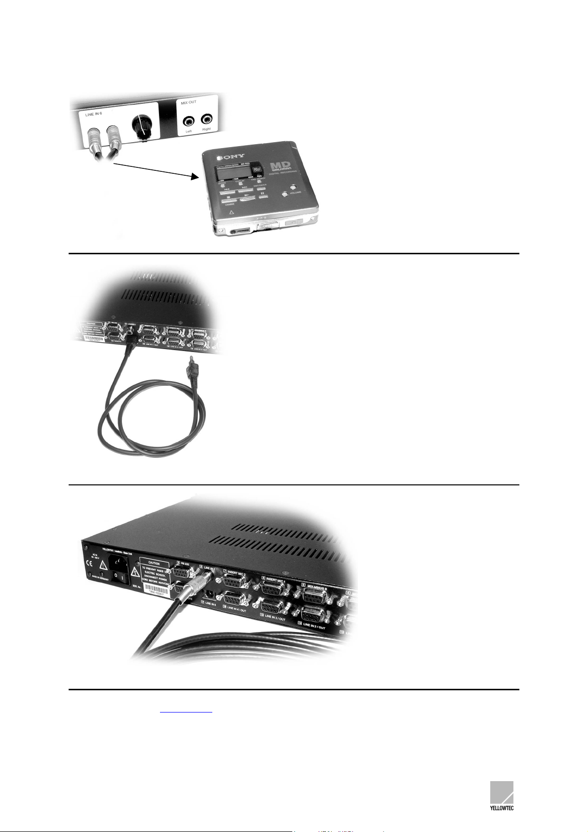
The following figures show connecting examples for the first operation.
Input for MiniDisk (or any other external audio source)
Optical cable (to connect equipment with optical output connection)
Connection example SPDIF Cable
Refer to the chapter BASE UNIT
in this manual for detailed information on the inputs/outputs and
connector assignments and for information on the technical data and the socket assignments.
INTELLIMIX® Manual 2.21 Yellowtec 2002 Page 13

3.5 Starting the configuration software quickly
3.5.1 Connection to the computer
You may use the INTELLIMIX® configuration software to create setups of your own for INTELLIMIX®
on your PC.
First of all, establish a connection between your PC and INTELLIMIX®.
Use the short enclosed interconnecting cable. Use the connector 9 (RS232) on the base unit and a
free serial interface on your PC.
Connection between Intellimix Base Unit and Laptop/PC
INTELLIMIX® Manual 2.21 Yellowtec 2002 Page 14

3.5.2 Installing the software
To do so, a PC with Windows 95 or higher is required.
3.5.2.1 Installing the CD-ROM
Insert the CD-ROM into the drive and start the (INSTALL.EXE) installation routine. The software will
guide you conveniently through the installation process.
All required data is copied to your computer. No parameters of your computer will be modified.
Note:
For trouble free operation you need at least the following elements:
- IMX.EXE configuration software
- IMXVxxx.IMU firmware for base unit (xxx stands for version number)
- IMX.HLP help file for online-help
- IMX.CFG configuration file for first program start (strongly recommended, but not
absolutely necessary)
3.5.2.2 Installation as an update
Please refer to our website http://www.yellowtec.com/
a download at no cost.
Read UPDATING INTELLIMIX®
version number of the software you use.
Never perform an update without refering to UPDATING INTELLIMIX®
TECHNICAL DRAWINGS/DESCRIPTIONS)
For trouble free operation you need at least the following elements:
Note:
- IMX.EXE configuration software
- IMXVxxx.IMU firmware for base unit (xxx stands for version number)
- IMX.HLP help file for online-help
- IMX.CFG configuration file for first program start (strongly recommended, but not
absolutely necessary)
for questions concerning updates, describing how to find out the
for the latest INTELLIMIX® software version for
first. (See Chapter
INTELLIMIX® Manual 2.21 Yellowtec 2002 Page 15
3.5.3 First steps
Start the IMX.EXE program.
(The short-cut automatically generated by the installation routine for the IMX.EXE program is named
Intellimix.)
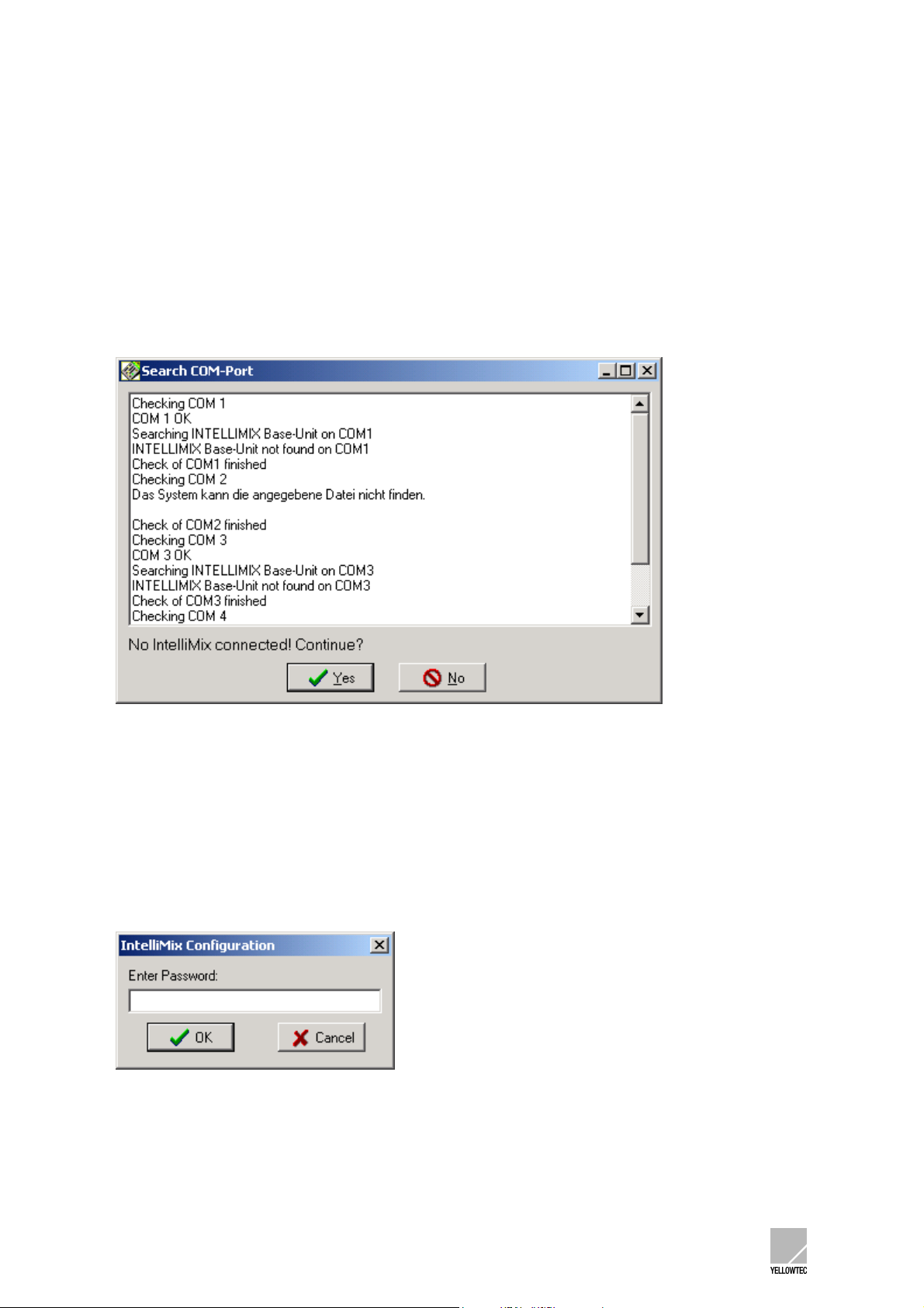
Starting the program causes the configuration software to search for a connected INTELLIMIX® at the
serial interfaces of your PC. If no INTELLIMIX® is found, the following dialog will appear (the text may
vary depending on the PC).
Clicking on the YES button starts the configuration software offline.
In the offline mode you may, for example, edit setups stored in your PC and store them again. In
addition, this mode is suitable for a familiarisation or for demonstration purposes.
If you wish to work with INTELLIMIX®, click on NO and check the connection between INTELLIMIX®
and the PC. Then, restart the configuration software.
If a connected INTELLIMIX® is found, the configuration software will be called up directly, and the
following window opens:
The configuration software provides a password protection. The password in the delivery state is imx.
Enter imx and click on OK
INTELLIMIX® Manual 2.21 Yellowtec 2002 Page 16

The graphical user interface of the configuration software provides 4 menus and 6 pages in a
register card format.
The 4 menus provide the Basic functions, and the 6 pages in the register card format allows
parameter settings for INTELLIMIX®.
Take your time to view the user interface of the software.
Most of the settings are self-explaining. Settings are performed with the mouse or via the keys.
Attempt to modify the settings.
As long as the Save to Unit command is not selected, your settings will not be transferred to
INTELLIMIX®. To return to the basic settings, you may exit and restart the program at any time.
The software provides a context sensitive online help which can be called up by pressing the
function key F1. Read the Tips on online help at the start of the help text.
All functions are explained clearly on the online help.
The SOFTWARE
chapter in this manual details all functions and settings.
The software (and/or the update) includes the imx.cfg file. During the start the configuration software
refers to the default settings stored in this file (the file must be in the same folder as the configuration
software).
We recommend, especially if you are not well familiar with the configuration software, the use of these
basic settings as the starting base for your setup to avoid malfunctions by wrong or missing entries.
All labels for a selection of the input sources have values which allow a simple assignment:
- Microphone inputs with a text „MIC1“ „MIC2“ „MIC1+2“
- All other inputs numbered from 1...12 with the addition “A” for analog or “D” for digital
- Inputs 5 and 6 with the addition “co” for consumer format.
The default source selection has been tailored for a first test operation which can normally be
performed without any cable adapter:
Fader 1: Microphone 1 (XLR input on the front panel)
Fader 2: Input 5, digital consumer format, preset to TOS link optical
(TOS link connector on the back panel)
Fader 3: Input 6, analog consumer format (cinch connector on the front panel)
Monitor: Mix signal for listening
Note
: Depending on the software version, other basic settings may be provided in the delivery state.
IMPORTANT
transferred to INTELLIMIX® unless the Save to Unit
: When working with the configuration software, be aware that your settings are not
command has been selected.
INTELLIMIX® Manual 2.21 Yellowtec 2002 Page 17

4 CONTROL UNIT
4.1 Fader
INTELLIMIX® provides three 100mm faders. The identification in the upper third can be used as a
0dB reference. The control range from the identification to the maximum setting is approx. 8 dB.
In addition to the level setting, INTELLIMIX® also uses the fader setting to evaluate a switching
function (Fader Start) at the lower fader end (off-) position. This is displayed by the Fader Start
indicator and available for internal controls: Refer to ON-AIR Logic. Refer to Trigger Outputs for
external controls. Other setting options linked to the fader: PFL (Prefade Listen)
4.2 Fader Start indicator
Each fader includes a Fader Start indicator in the form of a red LED at the lower fader end (Off-) position. It will light up if the respective fader is not in its Off position. As described under Fader, INTELLIMIX® will evaluate the fader position for the Fader Start function. Refer to Fader
for an explanation and the links.
INTELLIMIX® Manual 2.21 Yellowtec 2002 Page 18

4.3 Source Selector / PFL
Each fader includes a Source Selector in form of a rotary transducer with a pushbutton function.
Turn the Source Selector to select the desired input source for the respective channel.
Note
: The Source Selector function will only by active when the fader is in its Off position to protect the
Source selection against an inadvertent misadjustment during the current operation.
Keeping the Shift key pressed while the Source Selector is turned changes its function. Now, select
the mode for the stereo channel (stereo/mono/L/R) or the balance for the mono channels. Refer to the
options for Stereo fader (balance)
Optionally, you may control other parameters. Refer to Source Selector with Shift
Other topics linked to the Source Selector: Disable Source Selection
Display, Shift (Application Level-2)
Press the Source Selector and activate PFL (Prefade Listen)
Source/Status display. The Pushbutton function may also be used for external controls. Refer to
Trigger Outputs
.
.
.
, Default Source, Source/Status
which is shown by a blinking of the
4.4 Level indicator
Each fader includes a level indicator. This LED chain is normally used as a level trend display. Refer to Level Indicator It is also used as a trend display for the optional Balance and Input Trim Source Selector functions. Refer to Source Selector with Shift position”.
for explanations and options.
. Here, the LED under the arrow in the middle is used as a “zero
4.5 Source/Status display
Each fader includes a Source/Status display.
This 4-digit alphanumeric display normally shows the selected source. Refer to Label
Keeping the Shift button pressed displays the Shift function of the Source Selector, i.e.
stereo/mono/L/R, panorama or balance.
The display changes to the blinking mode once PFL (Prefade Listen)
the options.
is selected. Refer to Display for
.
INTELLIMIX® Manual 2.21 Yellowtec 2002 Page 19

4.6 Attention indicator
Each fader includes an Attention indicator, an LED beside a warning triangle symbol. It lights up to
draw your attention to unusual settings or settings deviating from the zero position. It can be
deactivated as required. Refer to Display
for the functions and options.
4.7 Out Of Phase indicator
Each fader includes an Out Of Phase indicator in the form of an LED with a phase symbol (circle with
a dash). INTELLIMIX® evaluates the phase angle of stereo signals and will signalise “out-of-phase”.
The display can be deactivated as required. Refer to Display
for the functions and options.
4.8 Monitor Control
Turning monitor control sets the listening volume of INTELLIMIX®. Pressing the button toggles
between the monitor output and the headphone output.
Refer to SmartLevel
Turning monitor control while the Shift key is pressed allows a selection of the monitor source. Refer to Disable Monitor Selection
Monitoring Level DIM-Level Option for Headphones for the respective settings.
for the settings.
4.9 Monitor Source display
This 4-digit alphanumeric display shows the selected source. Refer to Label.
Refer to Flash Monitor Display
for the options.
4.10 Speaker/Headphone indicator
Two LEDs beside the respective symbols show whether the headphone output or the monitor output
(for connecting the loudspeaker amplifier) has been selected.
The LED assigned to the monitor output will be blinking if this output has been selected, but is muted.
Refer to PFL Options for Loudspeakers
settings.
PFL Options for Headphones Option for Headphones for the
INTELLIMIX® Manual 2.21 Yellowtec 2002 Page 20

5 BASE UNIT
5.1 Front panel
The INTELLIMIX® front panel only contains elements which are useful for the user for a direct access.
1. Headphone connection, stereo jack, 6.3mm
2. Mic 1 input, XLR, 3-pin
3. Mic 2 input, XLR, 3-pin
4. Line In 6 Left, cinch
5. Line In 6 Right, cinch
6. Potentiometer for setting the input amplification for the line in 6 inputs
7. Mix Out Left, cinch
8. Mix Out Right, cinch
9. Green Status LED, signalising readiness of operation, blinking in the Standby Mode
10. Red Reset LED, signalising the Reset mode or a malfunction.
Refer to the INTELLIMIX® Pinout Table
Refer to Technical Data
for the connection specifications.
for the connections and the exact pin assignments.
INTELLIMIX® Manual 2.21 Yellowtec 2002 Page 21
 Loading...