


Vision Meter Family
User’s Manual

Partnered with
Intellimeter.ca
Table of Contents
Introduction ................................................................................................... 3
1. Product Description .................................................................................. 3
1.1 ST Single Phase Meter ...............................................................................................3
1.2 XT Poly Phase Meter .................................................................................................4
1.3 Network Connectivity ................................................................................................4
1.4 Weight ........................................................................................................................4
1.5 Temperature ...............................................................................................................5
1.6 Frequency ...................................................................................................................5
1.7 Catalog Information ...................................................................................................5
1.8 Operational Theory ....................................................................................................6
2. Installation ................................................................................................. 7
2.1 Meter Installation .......................................................................................................7
3. Operational Instructions .......................................................................... 9
3.1 Nameplate Information ..............................................................................................9
3.2 Display Information .................................................................................................10
3.3 Accumulation Modes ...............................................................................................11
3.4 Instantaneous Power .................................................................................................11
4. Maintenance ............................................................................................ 12
4.1 Test Procedure ..........................................................................................................12
4.2 Service ......................................................................................................................14
4.3 Storage ......................................................................................................................14
4.4 Troubleshooting .......................................................................................................14
5. Diagrams .................................................................................................. 15
5.1 ST Single Phase Meter .............................................................................................16
5.2 XT Poly Phase Meter ...............................................................................................17
6. Supplementary Information .................................................................. 18
6.1 ANSI C12.10 Internal Connections .........................................................................18
1125 Squires Beach Road, Pickering, ON, L1W 3T9 • Tel: (905) 839-9199
Page 2
Intellimeter Canada Inc.
Copyright 2015 © Vision Metering, LLC

Partnered with
Intellimeter.ca
Introduction
The Vision Meter Family consists of a variety of single phase and poly phase meters with
network connectivity options. Meters can be ordered to include either Data on Demand ™,
Airpoint ™, or both hardware options. All Vision meters are programmed through the
Vision 20/20 software which is included in all Vision meters. All meters are designed with
a lifetime to exceed 20 years, meeting or exceeding ANSI standards, using digital
measurement technology.
1. Product Description
The Vision Metering family of meters includes single phase (ST) meters and poly phase
(XT) meters. The meters are configured to the customer’s specifications within a tolerance
of (+/-0.15%) from the factory, ensuring a smooth installation process and accurate
measurement. Also standard is the ability to complete delivered, received, and net
metering.
1.1 ST Single Phase Meter
The standard (ST) model meter has been designed with cost in mind, yet considers
upgradability by offering features that can be added on at a later date.
The ST single phase meter can be configured for a number of options:
Available in Form 1S, 2S, 3S, 4S, & 12S. Other forms are available upon request.
Available in 120V, 240V, or 480V rated Voltage.
Displays kWh, instantaneous demand, volts, and amperes
Standard functions include Time of Use, Load Profile, Demand.
Comes in Class 320, Class 200, 100, and transformer rated types.
Optional 15 Year Battery
Optional radio with Data On Demand or ERT transmission capabilities
ERC and FCC/NTC Approved
Customer Programmable (with Vision 20/20 software)
1125 Squires Beach Road, Pickering, ON, L1W 3T9 • Tel: (905) 839-9199
Figure 1
Page 3
Intellimeter Canada Inc.
Copyright 2015 © Vision Metering, LLC

Partnered with
Intellimeter.ca
1.2 XT Poly Phase Meter
The XT Poly Phase meter is equipped with the features present in the ST meter model
with the following features in addition:
Available in ANSI Forms:
1S, 2S, 3S, 5S, 6S, 8S/9S, 12S/25S, 13S, 15S/16S, 35S, 45S
Power Supply capable of handling 120V – 480V
Optional KYZ output for additional pulse generation capabilities
The XT meter has been designed to accommodate all metering forms and to provide a
platform for AMR/AMI manufacturers to add communication hardware as needed to the
meter unit. Literature is available to assist customers.
Figure 2
1.3 Network Connectivity
The XT meter includes an internal HP RF radio that operates on the 900 MHz band
transmitting SCM data. The ST and XT models can be ordered to include Airpoint high
power automatic meter reading hardware.
1.4 Weight
The shipping weight for each type of meter is different and is as follows:
Single Phase ST meter with Polycarbonate Housing
o Single meter: 1.5 lbs
o 4 meter box: 7.0 lbs
o Pallet of 120: 229 lbs
Polyphase ST meter with Polycarbonate Cover
o Single meter: 2.0 lbs
o 4 meter box: 9 lbs
o Pallet of 96: 241 lbs
1125 Squires Beach Road, Pickering, ON, L1W 3T9 • Tel: (905) 839-9199
Page 4
Intellimeter Canada Inc.
Copyright 2015 © Vision Metering, LLC
Partnered with
Intellimeter.ca
Singlephase XT meter with Glass Cover
o Single meter: 2.4 lbs
o 4 meter box: 10.6 lbs
o Pallet of 120: 337 lbs
1.5 Temperature
Vision meters are specified to perform from -40° C to 85° C. The LCD may cease to
function in adverse cold weather below -30 ° C, or excessive heat, above 80° C. Storage
temperature should be between -40° C to 85° C.
1.6 Frequency
Vision meters can accurately measure energy associated with 50 Hz or 60 Hz electric
systems. Operating frequency is set at the factory and must be specified when ordering
the meter.
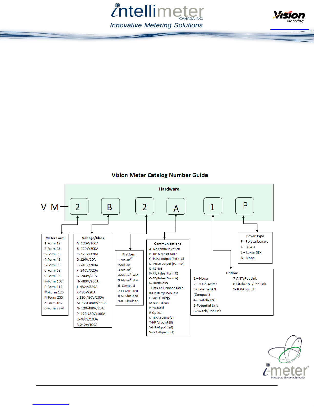
1.7 Catalog Information
The catalog displays information regarding the different meters included in the catalog
through an alphanumeric code, as shown in Figure 3.
Note: Demand meters must be built on the Vision XT platform with a 120V-480V power
1125 Squires Beach Road, Pickering, ON, L1W 3T9 • Tel: (905) 839-9199
Figure 3
supply.
Page 5
Intellimeter Canada Inc.
Copyright 2015 © Vision Metering, LLC

Partnered with
Intellimeter.ca
1.8 Operational Theory
The operations within the meter are explained as follows:
The meter is driven by a microcontroller powered by a DC source drawing power
from line voltage. An analog to digital converter is connected to before and after
the current transformer to measure Watt-hours.
The microcontroller stores accumulated data in the NVRAM and displays the
data as programmed in Vision 20/20. This data is stored in RAM that is nonvolatile, thus power does not need to be applied for the data to be retained.
The LCD is powered through the microcontroller and displays according to the
user’s settings.
The block diagram in Figure 4 shows the component interaction within the Vision
family of meters.
1125 Squires Beach Road, Pickering, ON, L1W 3T9 • Tel: (905) 839-9199
Figure 4
Page 6
Intellimeter Canada Inc.
Copyright 2015 © Vision Metering, LLC
Partnered with
Intellimeter.ca
2. Installation
WARNING: The Vision ST and XT models contain dangerous levels of voltage. The
meter should never be disassembled, exposure to electrical connections within an energized
meter can result in serious injury or death.
Both the Vision ST and XT models come in a variety of ANSI standard forms. The physical
dimensions of the ST and XT models are different, as are the features on the polycarbonate
cover. The XT polycarbonate cover includes a turnkey feature that enables connection with
the internal button interface without removing the polycarbonate protective housing.
2.1 Meter Installation
The installation of the Vision meters should be handled by licensed professionals. The
meter is plugged into the meter socket jaws, engaging the terminals and connecting the
meter to the grid. Refer to Section 6 for supplementary diagrams of the common ANSI
electric meter forms.
Upon powering the meter, verify meter operations by checking the display. As shown in
Figure 5, the LCD display will energize.
As each meter is configured to the specifications provided by the customer, the meter
settings will already be installed on the meter as tested at the factory. After installation and
powering of the meter, the meter settings should be checked for proper operation of the
meter. As shown in Figure 6 on page 8, the front of the meter contains the optical port
connection necessary for communicating with meter.
The LCD display meets or exceeds ANSI C12.1, C12.10, C12.20, C37.90.1 standards.
Note: Both an optical port and Vision 20/20 are required to read the meter settings.
Refer to the Vision Metering website for a current version of the Vision 20/20
software as well as the associated user’s manual.
1125 Squires Beach Road, Pickering, ON, L1W 3T9 • Tel: (905) 839-9199
Figure 5
Page 7
Intellimeter Canada Inc.
Copyright 2015 © Vision Metering, LLC
Partnered with
Intellimeter.ca
Figure 6
1125 Squires Beach Road, Pickering, ON, L1W 3T9 • Tel: (905) 839-9199
Figure 7
Page 8
Intellimeter Canada Inc.
Copyright 2015 © Vision Metering, LLC

Partnered with
Intellimeter.ca
Attach the optical port as shown in Figure 7 on page 8. Using the Vision 20/20 software,
click Read Meter to transfer the data on the meter to the Vision 20/20 software. If the
configuration screen in Vision 20/20 is populated with the correct test data, the meter can
be concluded to be operating correctly.
3. Operational Instructions
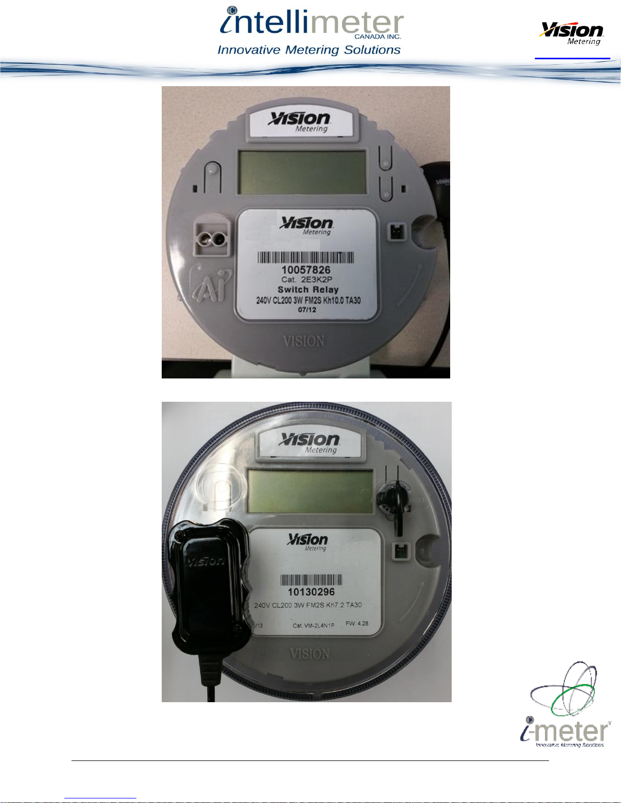
3.1. Nameplate Information
As shown in Figure 6 and in Figure 7 on page 8, the nameplates have different layouts.
Displayed on the front of the meter is the operating voltage, the current measurement class,
the form type, the Kh value, and the test amperage value.
The nameplate information is displayed differently on the ST and the XT variants, though
the information displayed on either nameplate is the same.
The nameplate information shown in Figure 8 is as follows:
1. Power Supply Voltage Rating
2. Current Class
3. Watts used by the meter
4. Form Type based on ANSI C12.10
5. Kt value for one revolution, in Wh
6. Test Amperage Rating
1125 Squires Beach Road, Pickering, ON, L1W 3T9 • Tel: (905) 839-9199
Figure 8
Page 9
Intellimeter Canada Inc.
Copyright 2015 © Vision Metering, LLC

Partnered with
Intellimeter.ca
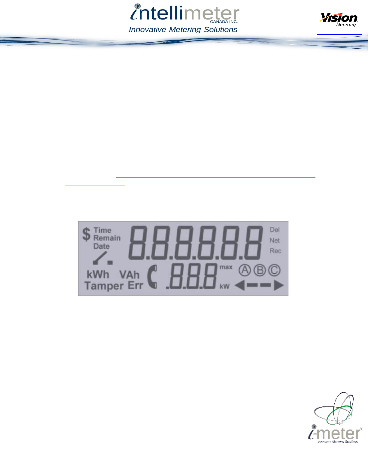
3.2. Display Information
The liquid crystal display (LCD) on the front of the meter can be programmed to display
variety of values. On the top row of the display, the accumulated information is displayed.
Both the accumulated and displayed information can be programmed using the included
Vision 20/20 software. The ability to check if a switch is present in the meter is also
included in the Vision 20/20 software suite.
As shown in Figure 9, the LCD displays a variety of information:
1. The main six digit display shows the programmed data as set in Vision 20/20
2. Operating Mode indicator
3. Phase Letter indicator
4. When displayed, the arrow to the right indicates energy is being delivered to the
load, the arrow to the left indicates the customer is generating energy to the grid.
This set of four symbols is also used to emulate a Watt-hour disk unit.
5. Max Demand displayed in kW
6. Phone Symbol – When displayed, indicates that communication is in progress. If
icon is constant, indicates transmission of data, if blinking, indicates data loss.
7. Tamper error indicator
8. kWh/VAh mode for six digit segment
9. Switch Open indicator – if blinking, indicates a switch failure
10. Dollar Sign – Not Used
11. Time Display Settings
1125 Squires Beach Road, Pickering, ON, L1W 3T9 • Tel: (905) 839-9199
Figure 9
Page 10
Intellimeter Canada Inc.
Copyright 2015 © Vision Metering, LLC

Partnered with
Intellimeter.ca
3.3. Accumulation Modes
Accumulated information can be set to display the following modes:
Net Metering (Delivered – Received):
The Net Metering mode measures both the delivered and received power and takes the
difference. This mode is most appropriate for renewable energy generation provided by a
grid connected customer that draws more power than generated.
Delivered Only:
The Delivered Only mode allows only the power delivered to the customer to be
recorded. This mode is the most common metering mode on residential systems. It is anti
- tampering mode as well. If power is flowing in received direction, meter will also
record it as delivered.
Received Only:
The Received Only mode allows only the power delivered from the customer to the grid
to be measured. This mode is most appropriate when the customer has a large generation
facility with no demand.
3.4. Instantaneous Power
When enabled in the display settings, the lower three digit display will display the
instantaneous demand experienced by the meter. Decimal location and demand range can
be set by changing the Precision Settings using Vision 20/20 software.
1125 Squires Beach Road, Pickering, ON, L1W 3T9 • Tel: (905) 839-9199
Page 11
Intellimeter Canada Inc.
Copyright 2015 © Vision Metering, LLC

Partnered with
Intellimeter.ca
4. Maintenance
4.1. Test Procedures
All Vision Meters are equipped with a Light Emitting Diode (LED) and a phototransistor
for ensuring proper calibration of the meter according to ANSI standard C12.20. The
infrared LED emits pulses indicating kWh accumulation. Each pulse represents Kt,
measured in Wh of energy accumulated by the meter. An optical probe and the associated
driver is required to communicate the pulse information from the optical port to the
connected computer.
Figure 10 shows the Optical Port, showing both the LED and the Phototransistor in the
configuration present on all Vision Metering optical ports:
1. Infrared LED 2. Phototransistor
Testing of the meter unit involves reading test data fed to the meter, which if the meter
operates correctly, should be read with the desired accuracy to the Vision 20/20 software.
Emulation of a disk analog system is accomplished using the symbol in the bottom right
corner of the LCD as shown in Figure 11 on page 13. The emulation procedure consists of
blinking the various sections of the symbol to show that a revolution has occurred. The 10step emulation procedure is shown in Figure 11 on page 13.
1125 Squires Beach Road, Pickering, ON, L1W 3T9 • Tel: (905) 839-9199
Figure 10
Page 12
Intellimeter Canada Inc.
Copyright 2015 © Vision Metering, LLC

Partnered with
Intellimeter.ca
Figure 11
The emulation procedure starts as soon as load is applied. It is preferable that this load be
well known and constant for the test procedure. The disk emulation is completed by
timing the full cycle for Kt. For higher accuracy, increase the number of cycles per test.
A general testing procedure for disk emulation of electric meters is listed below:
1. Record the Kt value recorded on the nameplate of the meter.
2. Select the desired voltage and current on test equipment, ensuring the device
ratings are within the range of the desired specifications.
3. Install the meter to the test socket, ensuring the correct form socket is selected
4. Attach the optical probe to the optical port.
5. Using standard test procedure, begin testing after 15 seconds so the demand is
stabilized.
6. To ensure accurate measurement, establish a minimum of 30 seconds test time to
reduce human error caused by the imprecise start and stop times.
7. Compare the values given from the test to the values displayed on the unit. If the
values are within a reasonable error margin, the meter can be concluded to be
working properly.
1125 Squires Beach Road, Pickering, ON, L1W 3T9 • Tel: (905) 839-9199
Page 13
Intellimeter Canada Inc.
Copyright 2015 © Vision Metering, LLC

Partnered with
Intellimeter.ca
Name
Code
Display
Blocking
Cause
Required Action
ERR_UNPROGRAMMED
001
No
Meter is not programmed
or in a factory default state
This error is set when
firmware takes default
setting data during
initialization after power
was up.
ERR_CONFIG
002
Yes
Meter detected a
configuration error
Currently not supported
by meter
ERR_SELFCHK
003
Yes
Meter detected a self-check
error:
Meter tried to recover
reading data from backup
memory after power was
up and did not found any
good records
Reset the meter.
ERR_RAMFAILURE
004
Yes
Meter detected a RAM
Memory failure
Currently not supported
by meter
ERR_ROMFAILURE
005
Yes
Meter detected a ROM
Memory failure
Currently not supported
by meter
ERR_NONVOLMEMFAILURE
006
Yes
Meter detected a nonvolatile memory failure.
Meter tried to save reading
data in the EEPROM
memory unsuccessfully.
Call to the manufacturer
if this error has not gone
after 5 minutes.
ERR_CLOCK
007
No
Meter detected a clock
error
Currently not supported
by meter
ERR_MEASUREMENT
008
Yes
Meter detected a
measurement element error
Currently not supported
by meter
ERR_LOWBATTERY
009
No
Meter detected a low
battery error
Replace the battery
ERR_LOWLOSSPOTENTIAL
010
No
Meter detected one of the
device potential that is
below a predetermined
Check the meter
connection to the
network.
4.2. Service
Vision Meters are calibrated at the factory and do not require any maintenance. If there
are issues with the meter, contact Vision Metering for assistance.
4.3. Storage
Vision meters are durable devices, yet they should be stored with care. Extreme
temperature and humidity levels should be avoided during storage.
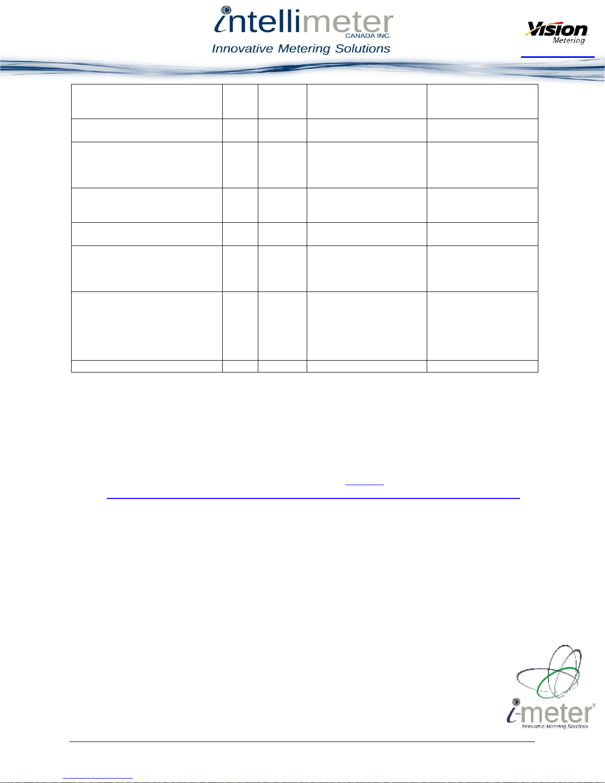
4.4. Troubleshooting
Troubleshooting of Vision Meters is accomplished by reading the error codes given by
the meter and performing the correct repair procedures. The complete table of error
codes and the required actions, is given in the table on pages 13-14.
1125 Squires Beach Road, Pickering, ON, L1W 3T9 • Tel: (905) 839-9199
Page 14
Intellimeter Canada Inc.
Copyright 2015 © Vision Metering, LLC
Partnered with
Intellimeter.ca
value.
Check if the meter formfactor settings matches
the faceplate label.
ERR_DEMANDOVERLOAD
011
No
Meter detected a demand
threshold overload
Currently not supported
by meter
ERR_POWERFAILURE
012
No
Meter detected a power
failure. Power register in
the computation engine
was corrupt
Cycle meter power. Call
to the manufacturer if
this error has not gone.
ERR_TAMPERDETECT
013
Yes
Meter detected tamper
activity. Used on meters
with the tamper sensors
Reset the tamper flag.
ERR_REVERSEROTATION
014
No
Meter detected reverse
rotation
Currently not supported
by meter
ERR_RADIO
101
Yes
Meter detected an error in
the radio chip. Used on
meters with the radio
communication
Cycle meter power. Call
to the manufacturer if
this error has not gone.
ERR_POWERSWITCH
102
No
Meter detected a power
switch error. Used on
meters with the
connect/disconnect switch.
Can be switch board or
switch malfunctioning
Replace switch board or
power switch
ERR_NOTCALIBRATED
103
No
Meter is not calibrated
Calibrate the meter
5. Diagrams
The physical dimensions of both types of meters are shown below. It may be desired to
acquire more information about the different types of form standards, it is recommended
to reference a reliable source for this information. Refer to
meteringforlinemen.com/diagrams for sample information about ANSI form standards.
1125 Squires Beach Road, Pickering, ON, L1W 3T9 • Tel: (905) 839-9199
Page 15
Intellimeter Canada Inc.
Copyright 2015 © Vision Metering, LLC

Partnered with
Intellimeter.ca
5.1 ST Single Phase Meter
Figure 12
The ST single phase meter has a different physical layout than the XT model. The ST series
of meters do not have as many features available and the exterior housing reflects the
difference. ST meters are available in both polycarbonate and glass housing types.
1125 Squires Beach Road, Pickering, ON, L1W 3T9 • Tel: (905) 839-9199
Page 16
Intellimeter Canada Inc.
Copyright 2015 © Vision Metering, LLC

Partnered with
Intellimeter.ca
5.2 XT Poly Phase Meter
Figure 13
Figure 14
Figure 15
The XT series meters have a different layout which includes an external switch to select
the settings for the meter. The XT series are readily available only in a polycarbonate
housing. To obtain an exterior housing in glass on the XT meters, a custom order must be
made, contact Vision Metering for custom orders.
1125 Squires Beach Road, Pickering, ON, L1W 3T9 • Tel: (905) 839-9199
Page 17
Intellimeter Canada Inc.
Copyright 2015 © Vision Metering, LLC
Partnered with
Intellimeter.ca
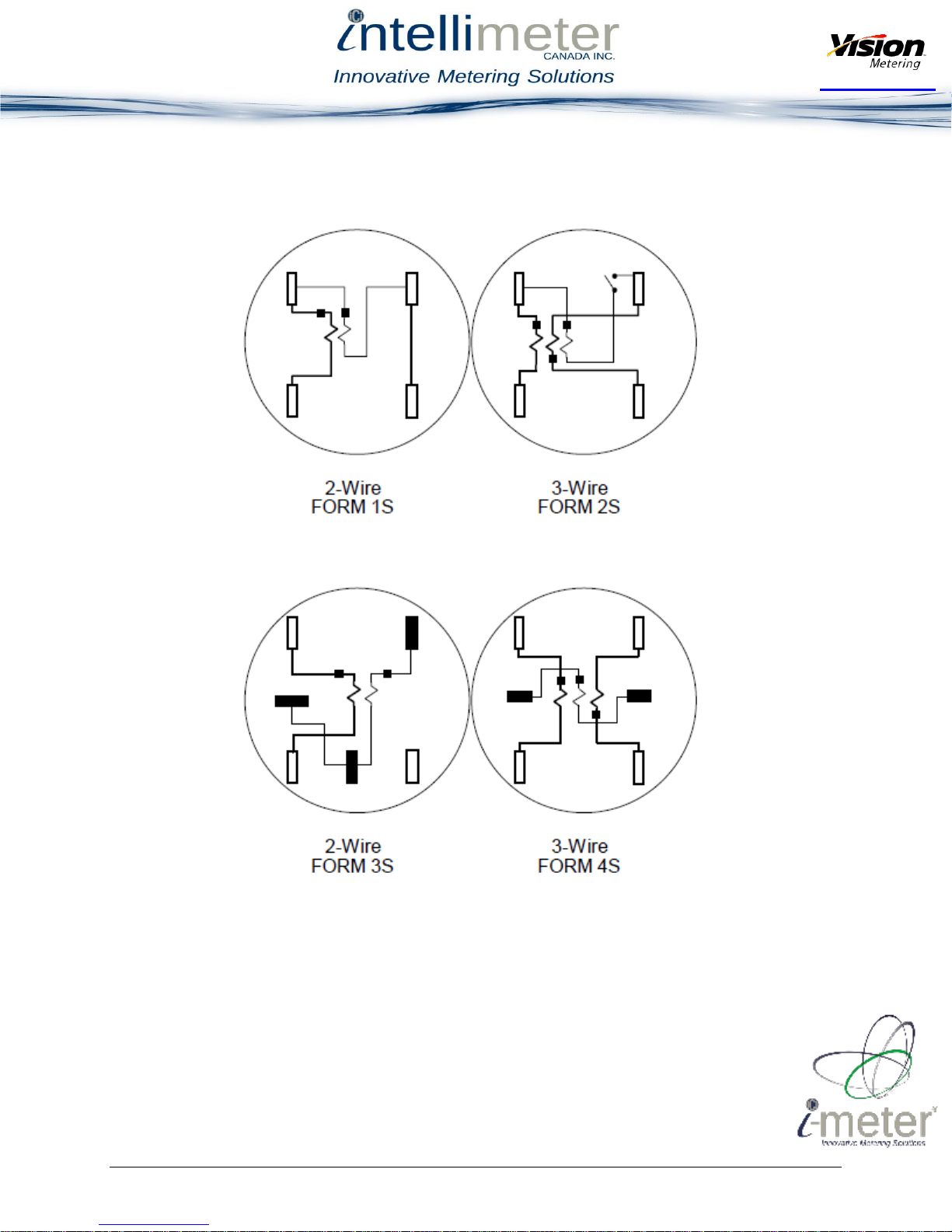
6. Supplementary Information
6.1. ANSI C12.10 Internal Connections
1125 Squires Beach Road, Pickering, ON, L1W 3T9 • Tel: (905) 839-9199
Figure 16
Page 18
Intellimeter Canada Inc.
Copyright 2015 © Vision Metering, LLC

Partnered with
Intellimeter.ca
1125 Squires Beach Road, Pickering, ON, L1W 3T9 • Tel: (905) 839-9199
Figure 17
Page 19
Intellimeter Canada Inc.
Copyright 2015 © Vision Metering, LLC

Partnered with
Intellimeter.ca
1125 Squires Beach Road, Pickering, ON, L1W 3T9 • Tel: (905) 839-9199
Figure 18
Page 20
Intellimeter Canada Inc.
Copyright 2015 © Vision Metering, LLC
 Loading...