

intellijel designs Corgasmatron User Manual
Corgasmatron Manual v1.0
The Corgasmatron is a two independent multi mode filters and a cross fader mounted behind a
16HP Eurorack panel. The Corgasmatron's sound can range from ultra clean and precise, to
extremely ballsy and dirty.The resonance is incredibly musical and interesting and is prime for
all sorts of experimenting and sound design. The normalling, routing and cv options have been
carefully selected to allow for a lot of control over the modules functionality and capabilities.
The original circuit was designed by analog guru david g. dixon after carefully studying and
analyzing the classic korg ms-20 filter. His work resulted in a completely original circuit based
around ssm2164 vca chips. This design is capable of almost identical results but is far more
versatile. This is not a clone, it is an entirely new and modern circuit with many enhancements.
Key features:
16HP and shallow (two pcbs in parallel so it is
•
skiff friendly)
two independent filters, each with LP, HP and
•
Notch modes.
Unique resonant (Q) drive control
•
A Switch links the two filters allowing both
•
parallel and serial routing via normals to input B
(which can be broken by inserting a cable at
input B).
Oscillates very easily and can be used as a
•
dual sine VCO. Using the resonance controls
this Sine shape can be colored.
1V/Oct inputs for each filter
•
Built in full featured cross fader allows voltage
•
controlled xfading between the two filters. The
Xfade has a switch to select either unipolar
(e.g. envelopes) or bipolar (e.g. lfo) control of
the xfade position. There is also a switch to
select direction. With nothing plugged into the
Xfade jack the xfade knob controls the fade
position. When an external CV is patched in the
same knob acts as an attenuator for the control
signal.
Jumpers on the back to select "modern" or
•
"vintage" resonant modes (two different
feedback paths for the resonance that use
different diodes)
Expansion jacks for adding additional filter
•
inputs and VC control of resonance
Page 1 of 10

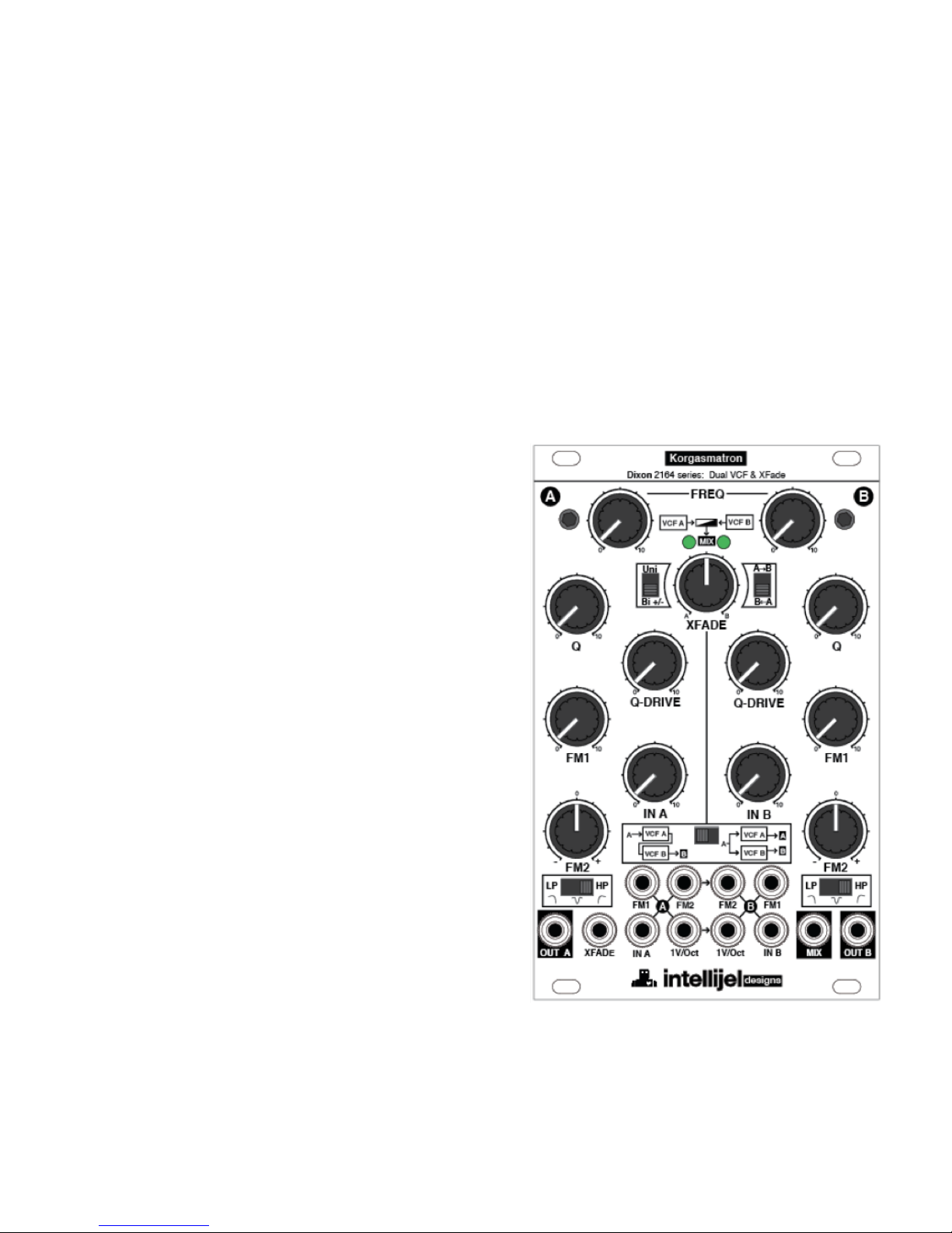
Front Panel
1- FREQ - Cutoff frequency of
the filter. This sets the center
frequency of the filter.
2- Xfader section. XFADE
position knob, CV polarity
switch and Xfade direction
switch. The Xfade knob acts
as cross fader in Parallel
configuration and using MIX
out if nothing is plugged into
the Xfade jack. Once patched
the Xfade knob becomes a
CV attenuator.
3- Q is also referred to as
resonance. Depending on
input gain moving this knob
past 1 oʼclock will cause the
filter to start oscillating.
Corgasmatron Manual v1.0
4- Q-DRIVE - is the level of
the resonance. This control is
also used to alter the timbre
of the resonant sound if the
filter is self oscillating.
5- FM1 - Unipolar attenuator
for FM1 input.
6- IN A - Input attenuator controls the level into the filter. For classic tone keep this below 12
oʼclock. Higher gain will suppress the resonance of the filter and change its tone. The
combination of IN A level, Q and Q Drive knobs can alter the tone of the filter dramatically
from sweet to scathing - experiment!
7- FM2 - Bi-polar attenuator for FM2 input. This is a center detent knob. Turning the knob
CCW will apply inverted CV, turning the knob CW will apply positive CV.
8- Filter mode switch. The three modes are 1 pole High Pass, 1 pole Notch, 2 pole Low Pass
9- Input and output jacks. Outputs are surrounded by a black outline.
Page 2 of 10

FM1 A
CV input to VCF A filter cutoff, attenuated by FM1 A knob
FM2 A
CV input to VCF A filter cutoff, attenuated with inversion by FM2 A knob.
Normalled to VCF B FM2.
FM2 B
CV input to VCF B filter cutoff, attenuated with inversion by FM2 B knob. This
is a switching jack, inserting a plug here will break the normal from FM2 A.
Using this normal allows the same CV source patched into FM2 A to control
both filters. The bi polar attenuators can set opposite so as to lower the
frequency of one filter while raising the frequency of the other.
FM1 B
CV input to VCF B filter cutoff, attenuated by FM1 B knob
OUT A
Output of filter A
XFADE
CV input to Xfade section. This is a switching jack, when a plug is inserted
the XFADE knob becomes a CV attenuator. The Uni/Bi switch to the left of
the XFADE knob determines if this input is Unipolar or Bipolar. If using a
Envelope as a modulation source use Uni, If using. a LFO as a modulation
source use Bi.
IN A
Signal input to filter A. Patch a audio signal here to be filtered. The knob IN A
attenuates this signal. The input signal level alters the tone of the filter circuit
and the resonance behavior. For classic filter tone set the IN A knob to 11
oʼclock when using standard level modular VCOs.
1V/Oct A
CV input for filter frequency calibrated for 1V/oct standard. By patching the
1V/Oct output of your keyboard or MIDI to CV converter here the filter will
track the keyboard. This is normalled to the 1V/Oct CV input of filter B.
1V/Oct B
CV input for filter frequency calibrated for 1V/oct standard. This is switching
jack, inserting a plug here will break the normal from 1V/Oct A.
IN B
Signal input to filter B. Patch a audio signal here to be filtered. The knob IN B
attenuates this signal. See IN A for more detail. If you are using the
Corgasmatron in Serial configuration inserting a plug into this jack will break
the internal routing from filter A which may cause confusion.
MIX
Output of filter A and B mixed together. Use this output if the Corgasmatron is
in Parallel configuration and you want to mix the filters together to one
output.
OUT B
Output of filter B. In Series configuration use this output.
Corgasmatron Manual v1.0
Input and Output jacks (left to right top to bottom)
Page 3 of 10
 Loading...