


Smart. Ecient. Endless
Operation
Manual
Model: i201X
i251X
Intellihot Direct Vent Boiler/ Combination Water
heater. This product complies with ANSI Z21.13(2010) / CSA 4.9 Low Pressure Boiler and with
ANSIZ21.10.3 (2011) / CSA 4.3 Gas Water Heater. For
use as potable water heating and space heating.
Y PRESET FOR USE WITH
(POUR INSTALLATION À L'INTÉRIEUR SEULEMENT)
OR
CT
FA
TION ONLY
PRÉRÉGLAGES D'USINE POUR UTILISATION AVEC
L
m
ALLA
TURE
NATURAL GAS
Amps
GAZ NA
: . . . . . . . . . . . . . . . .
ect-Vent Automatic Instantaneous
: Btu/hr Maximu
Dir
(Type de gaz)
olt, 60 Hz, 5
FOR INDOOR INST
120 V
. . . . . . . . . . . .
(Entrer le Classement)
pe of Gas
. . . . . . . . . . . .
Ty
Btu/hr Minimum . . .
Input Rating
. . . . . . . . . . . . .
Maximum Inlet Gas Pressure:
(Pression de gaz d'arrivée maximum)
. . . . . . . . . . . . .
Minimum Inlet Gas Pressure:
(Pression de gaz d'arrivée minimum)
ter Pressure:
. . . . . . . .
Wa
Minimum Inlet Gas Pressure (for adjustments): . .
(Pression de gaz d'arrivée minimum (pour ajustements))
ter Pressure:
Wa
ciency / :
(Côté)
Energy Factor:
. . . . . . . . . . . . . . . . . .
From
Minimum Clearances
(Dégagements minimums)
Non-Combustibles
(Des non-combustibles)
2 in (50.8 mm)
5/8 in (15.8 mm)
6 in (15.2 cm)
1/2 in (12.7 mm)
12 in (30.4 cm)
146.2)
From Combustible
Construction
(D'une construction
combustible)
6 in (15.2 cm)
5/8 in (15.8 mm)
6 in (15.2 cm)
2 in (50.8 mm)
12 in (30.4 cm)
Maximum
(Pression d'eau maximum)
Minimum
(Pression d'eau minimum)
Recovery Rating: . . . . . . . . . . . . . . . . . .
(Caractéristique de recouvrement)
Thermal Effi
(Efficacité thermique / Facteur énergétique)
NOx Emissions:
(Émissions de NOx)
(Pursuant to South Coast Air Quality Management District Rule 1
(conformément au règlement 1146.2 du "South Coast Air Quality Management District)
Top of heater
(Dessus du chauffe-eau)
Back of heater
(Arrière du chauffe-eau)
Front of heater
(Avantdu chauffe-eau)
Side
Bottom of cabinet
(Côté canalisation)
r
te
eset
er Hea
y Pr
Wat
al Gas
actor
F
tur
Na
(Réglage en usine pour gaz naturel)
199,000
C. (3.20 kPa)
20,000
. . .
13.0 W.
C. (2.00 kPa)
W.
8.0
C. (2.00 kPa)
8.0 W.
150 psi (1034 kPa)
15 psi (103 kPa)
265 GPH (1003 LPH)
Up to 98% / 0.94
(Jusqu'à 98 % / 0.94)
Less than 20 ppm
(Moins de 20 ppm)
Serial Number:
(Numéro de série)
Intellihot Green Technologies Inc
2900 W. Main St.
(877) 835- 1705
Galesburg, IL 61401
info@intellihot.com
.intellihot.com
Phone:
www
Email:
b:
We
Box if
Gas
Check
Converted to
Propane
Cocher la case si converti au gaz propane
sion* to
er
nv
Field Co
opane Gas
(Chauffe-eau automatique instantané à ventilation directe)
Pr
(Conversion* sur place au gaz propane)
199,000
0
C. (2.62 kPa)
20,00
W.
10.5
C. (0.76 kPa)
C. (2.74 kPa)
3.0 W.
W.
11.0
150 psi (1034 kPa)
15 psi (103 kPa)
265 GPH (1003 LPH)
Up to 98% / 0.94
(Jusqu'à 98 % / 0.94)
Less than 20 ppm
(Moins de 20 ppm)
*Refer to Installation and Operation
manual for conversion procedure.
(Se référer au manuel d'installation et
de fonctionnement pour la procédure de
conversion.)
(Collant ETL)
ETL STICKER
.
IGT-LBL-0005-01
Certified to
NSF/ANSI 372
WARNING
If the information in these instructions is not followed
exactly, a fire or explosion could result causing
property damage, personal injury, or death.
— Do not store or use gasoline or other flammable
vapors and liquids in the vicinity of this or any
other appliance.
WHAT TO DO IF YOU SMELL GAS
• Do not try to light any appliance.
• Do not touch any electrical switch; do not use
any phone in your building.
• Immediately call your gas supplier from a
neighbor’s phone. Follow the gas supplier’s
instructions.
• If you cannot reach your gas supplier, call the
fire department.
— Installation and service must be performed by
a qualified installer, service agency, or the gas
supplier.
AVERTISSEMENT
Assurez-vous de bien suivre les instructions données
dans cette notice pour réduire au minimum le
risque d’incendie ou d’explosion ou pour éviter tout
dommage matériel, toute blessure ou la mort.
— Ne pas entreposer ni utiliser d’essence ou
ni d’autres vapeurs ou liquides inflammables
à proximité de cet appareil ou de tout autre
appareil.
QUE FAIRE SI VOUS SENTEZ UNE ODEUR DE GAZ
•
Ne pas tenter d’allumer d’appareil.
•
Ne touchez à aucun interrupteur; ne pas vous
servir des téléphones se trouvant dans
le bâtiment.
•
Appelez immédiatement votre fournisseur de gaz
depuis un voisin. Suivez les instructions
du fournisseur.
•
Si vous ne pouvez rejoindre le fournisseur,
appelez le service des incendies.
— L’installation et l’entretien doivent être assurés
par un installateur ou un service d’entretien
qualifié ou par le fournisseur de gaz.
To avoid product damage, personal injury, or
even possible death, carefully read, understand,
and follow all the instructions in the Installation
and Operation manuals before installing this
product. Improper installation, adjustment, alteration, or
maintenance can cause injury, loss of life, and/or property
damage. This water heater should be installed and
serviced by a qualified technician. The lack of proper
service can result in a dangerous condition.
This manual contains safety information, installation
instructions, and maintenance procedures. It must be left
with the homeowner or placed near the water heater in
a noncombustible place. The customer should retain this
manual for future reference.


Table of Contents
1. General Information
1.1 Items Shipped With Water Heater . . . . . . . . . . . . . . . 4
1.2 Contact Information. . . . . . . . . . . . . . . . . . . . . . . . . . . . 4
1.3 Serial Number Plate Locations . . . . . . . . . . . . . . . . . . 4
2. Safety
2.1 Safety Signal Words . . . . . . . . . . . . . . . . . . . . . . . . . . . . 5
2.2 Installation Warnings. . . . . . . . . . . . . . . . . . . . . . . . . . . 5
3. Operation
3.1 Control Panel . . . . . . . . . . . . . . . . . . . . . . . . . . . . . . . . . . 7
3.2 Display Icons. . . . . . . . . . . . . . . . . . . . . . . . . . . . . . . . . . . 7
3.3 Turning Water Heater ON and OFF . . . . . . . . . . . . . . 8
3.4 Resetting (Clear) Error Codes . . . . . . . . . . . . . . . . . . . 8
3.5 Setting the Time . . . . . . . . . . . . . . . . . . . . . . . . . . . . . . . 8
3.6 Setting the Domestic Water Temperature . . . . . . . 8
3.7 Setting Space Heating Temperature. . . . . . . . . . . . . 9
3.8 Real Time Parameter Display. . . . . . . . . . . . . . . . . . . . 9
3.9 Error Screen. . . . . . . . . . . . . . . . . . . . . . . . . . . . . . . . . . . 10
4. Programming
4.1 Modes of Operation . . . . . . . . . . . . . . . . . . . . . . . . . . . 11
4.2 Viewing and Setting Modes of Operation . . . . . . 11
5. Maintenance
5.1 Cleaning the Inlet Water Strainer. . . . . . . . . . . . . . . 15
5.2 Draining the Water Heater . . . . . . . . . . . . . . . . . . . . . 15
5.3 Filling the Water Heater . . . . . . . . . . . . . . . . . . . . . . . 16
6. Troubleshooting
6.1 Error Code Chart . . . . . . . . . . . . . . . . . . . . . . . . . . . . . . 17
6.2 Wiring Diagram Chart . . . . . . . . . . . . . . . . . . . . . . . . . 19
6.3 Operational Diagram . . . . . . . . . . . . . . . . . . . . . . . . . . 20
7. Serviceable Parts
7.1 Electrical Components . . . . . . . . . . . . . . . . . . . . . . . . 21
7.2 Blower, Gas Valve, and Exhaust. . . . . . . . . . . . . . . . . 22
7.3 Water Lines and Fittings . . . . . . . . . . . . . . . . . . . . . . . 23
7.4 Ignition Components. . . . . . . . . . . . . . . . . . . . . . . . . . 24
Multiple Units
8.
8.1 Modes of Operation . . . . . . . . . . . . . . . . . . . . . . . . . . . 25
. Warranty. . . . . . . . . . . . . . . . . . . .
9
Product Warranty Card . . . . . . . . . . . . .
10.
. . . . . . . . . . . . . .27
. . . . . . . .29
3 Operation

1. General Information
—
Ne
pas en
t
r
ep
oser
n
i ut
ilise
r
d
’esse
nce
o
u
n
i
d’a
u
t
r
es
vape
u
rs ou
liq
uid
e
s
i
nf
l
a
mmab
les
à
p
r
oximit
é d
e cet
appa
r
eil
o
u
d
e t
o
u
t
a
ut
r
e
a
ppar
eil.
Q
UE
FA
I
R
E
S
I
VO
US
SEN
T
EZ
UN
E
O
DE
U
R
DE
GAZ
•
Ne
pas
t
e
nt
er
d
’al
lumer
d
’app
ar
eil
.
•
Ne t
ouchez à au
c
u
n
i
nt
e
r
r
upteur
;
n
e pa
s
vous
servi
r
d
e
s té
lé
ph
o
ne
s
s
e
t
ro
u
va
n
t
d
a
ns
l
e
b
â
t
im
ent
.
•
App
elez
i
mm
édi
at
ement
votre
f
our
n
iss
e
u
r
de ga
z
d
e
pu
is
un
vois
i
n.
Sui
vez
les
i
n
s
t
ruc
tio
n
s
du fo
ur
niss
e
ur.
•
Si
vous
n
e
p
ouvez r
e
jo
in
d
r
e l
e f
o
ur
ni
s
se
ur
,
appe
l
ez
le ser
vice
d
es
i
ncend
i
es
.
—
L’in
s
t
a
ll
a
t
io
n e
t
l
’en
t
ret
ie
n
d
oivent
êt
r
e
a
s
su
r
és
p
ar
un
i
n
st
a
ll
at
e
ur
o
u
u
n ser
vice
d’en
t
r
et
ien
qu
al
if
i
é
ou p
a
r
l
e
f
ou
rn
isseur
de ga
z.
A
VERTI
SSEME
N
T
A
ssur
e
zvo
u
s d
e
b
i
en
sui
vre
l
e
s
i
n
st
r
u
ct
i
on
s
do
nnée
s
dan
s
ce
t
t
e
not
ice
pou
r
r
éd
u
i
r
e
au
m
i
nim
um
le
r
i
sq
ue
d
’
in
cen
d
ie
ou
d
’
exp
lo
si
on
o
u
p
o
ur
é
vi
t
e
r
t
out
d
o
m
m
age
m
a
t
ér
iel
,
t
out
e b
le
ssu
r
e
o
u
l
a mo
r
t
.
—
Ne
pas
entre
p
ose
r
ni u
t
il
iser
d’e
ss
e
nce o
u
ni
d
’a
utr
es
vap
eur
s
ou l
iquid
es
infla
mmab
les
à
pr
oxi
mité de cet
a
ppar
eil
o
u
de tou
t
autre
appa
r
eil
.
Q
UE
FA
IR
E
SI V
O
U
S
SEN
TEZ
UN
E
ODE
U
R DE
G
AZ
•
Ne pas t
en
t
er
d
’al
lu
mer
d’a
ppar
eil
.
•
N
e
t
ouche
z
à a
ucun i
nt
e
r
r
u
pteu
r; ne
p
as
vous
se
rvi
r
de
s
té
lé
p
ho
nes s
e t
r
o
u
van
t d
an
s
le
bâtimen
t
.
•
A
p
pele
z
imm
édia
t
em
ent
vo
t
r
e f
ou
r
nisseu
r
de gaz
d
e
puis
u
n
vo
i
s
in.
Sui
v
ez
l
e
s
in
str
u
c
t
i
on
s
du f
o
u
rnisseur
.
•
S
i
vous
ne po
uvez r
e
joind
r
e
le
fou
r
nisseur
,
app
el
ez
l
e
ser
vice
des
i
ncendi
es
.
—
L’in
s
tall
a
t
io
n e
t
l’e
ntr
etien
doi
vent
ê
t
r
e assu
r
é
s
par
u
n
inst
a
llateu
r
ou
u
n
ser
vice
d’e
n
tr
et
ien
qual
if
i
é
ou pa
r
le
fou
r
nisseur
d
e gaz
.
AV
ER
TIS
SEMENT
A
ss
ur
e
zvo
us
de bi
en
sui
vre
l
e
s i
nstruction
s
d
onné
es
dan
s
cet
te
n
ot
i
c
e
po
u
r
rédui
r
e
au
m
i
n
im
uml
e
ri
sq
u
e
d
’
i
n
cen
d
i
e
ou
d
’
e
xplo
si
on
o
u
p
ou
r
é
vi
t
er
to
u
t
d
o
m
m
age
m
a
t
ériel
,
t
o
ut
e
bl
e
ssur
e
ou
l
a
m
o
r
t.
1.1 Items Shipped With Water Heater
The following items are shipped with the water heater; upper
mounting bracket (1), condensate drain (2), communication
cable (3), Operation manual (4), and Installation manual (5).
Note: Items 6 through 9 are spare parts shipped with the
unit. Two 10A bus fuses (6), electrode seal (7), O-rings
#015 (8), and 30psi relief valve (9).
5
6
7
1
S
mar
Operation
Manual
Model: i200X
i250X
Int
ellihot
heater
Direct Vent
.
(2010)
This
p
rodu
/
Boi
ANSIZ
CSA
ct complies
4.9 L
21.
use as
10.3
o
w
Pres
(2011) /
p
otable
CSA
water
heati
If
t
h
e
i
n
e
forma
WARNIN
x
a
c
tly
t
,
pr
i
o
n
o
a
p
in t
e
fi
rt
r
e o
h
y
e
da
s
e
r
ma
expl
i
n
G
str
g
e
u
,
o
c
pe
si
t
ion
—
o
r
son
n
s
D
c
i
o no
a
s
ou
l
n
i
nju
l
o
d
t
v
r
s
r
y
e
a
tore or
,
s
pors
or
u
l
d
t ca
e
o
an
a
us
t
th
her ap
d
.
e
liquids
ga
s
pliance.
oline
in t
or
h
ot
e
W
her
v
ic
H
init
A
f
la
T
•
y
T
D
o
of
O
not
t
D
his
O I
t
ry
F YOU
•
to
D
o
light any
no
SMELL
t
any
t
o
uc
appliance.
ph
h
GA
one in
an
•
y
Im
elec
me
yo
ur
t
di
rical s
n
at
build
e
e
i
g
l
y
hb
w
ing.
o
it
ins
c
c
r
a
’
h;
s
ll
t
ruc
p
do
y
h
o
t
ions.
o
ur g
n
•
e
I
.
f
F
a
y
ou
s sup
ol
l
c
o
f
annot
w
ir
e
th
p
depart
li
e
e g
r
reac
as su
me
h
yo
nt
— I
.
ur ga
n
s
t
s
allat
su
a
pplier,
ion
qu
alif
and
c
s
ied
upplier.
se
ins
r
v
ice
t
aller,
m
ust
s
erv
be
ic
pe
e
agency,
r
f
orm
or
8
SPARES
ler/ Combin
a
with
t
ion Wat
sure B
ANSI
o
er
Z21.13-
iler
4.
3 Ga
and
s Wa
with
ng a
t
nd
er Heater
spac
e
. F
h
e
or
ati
ng.
f
i
x
o
B
k
c
e
h
o
C
t
d
e
rt
e
v
n
o
s
C
a
G
e
ne
n
a
a
op
p
pr
o
z
r
ga
P
u
a
i
rt
e
nv
o
c
i
s
e
s
)
a
e
c
t
a
c
l
e
r
r
i
e
h
d
n
oc
o
C
i
t
a
l
i
t
H
n
T
ve
I
à
é
n
W
a
t
E
n
a
st
US
n
i
e
R
u
q
i
C
O
t
E
a
V
F
A
m
o
o
N
T
t
t
O
u
I
E
a
T
*
A
u
S
S
n
a
I
e
E
L
o
-
I
i
T
e
R
f
U
s
f
u
r
P
R
a
U
e
h
O
Y
v
P
(C
n
E
N
I
r
OR
S
Co
e
U
'
T
D
d
C
at
S
l
e)
E
n
s
e
)
A
G
a
i
T
A
a
F
N
op
L
F
He
E
G
G
pr
r
É
M
R
az
e
e
É
g
t
R
ULE
n
u
P
E
a
a
a
S
e
p
R
W
ac
U
l
o
p
E
r
s
r
RI
u
P
RAL GAS
u
s
t
TÉ
*
o
e
N
I
on
s
e
i
L'
s
e
À
er
r
v
an
N
P
t
O
on
I
C
T
n
(
ry
LA
a
L
t
o
t
TA
c
S
ns
N
)
a
I
l
s
ATU
I
e
L
R
F
a
ur
U
c
E
i
O
at
G
Y
R
t
n
P
(
L
l
U
0
a
az
T
N
a
g
0
r
A
0
ON
m
ur
N
,
u
o
o
t
9
p
t
9
a
AZ
ON
ne
1
u
i
I
G
N
s
T
u
A
n
A
t
e
L
e
n
g
L
.
a
e
l
A
g
.
T
é
V
-
R
.
S
(
0
t
0
N
.
I
c
0
,
.
e
R
0
)
.
s
ir
2
O
a
.
D
O
P
mp
.
k
D
A
.
N
2
I
5
6
.
.
,
0
R
2
z
.
0
(
O
H
0
.
.
,
F
C
0
9
.
6
9
W.
,
1
.
t
l
.
5
o
.
.
.
0
V
)
.
:
1
a
0
.
2
P
1
k
z)
6
0
a
7
0
g
.
0
0
,
mum
de
i
(
0
.
x
)
pe
2
y
s
a
a
T
.C
a
(
P
M
.
G
k
W
r
f
.
h
0
)
0
/
o
.
2
.
a
.
u
3
t
e
3
P
(
p
B
k
.
m
y
:
4
u
T
C
.
7
.
m
i
W
)
2
(
n
nt
i
.
0
e
.
m
C
M
3
e
.
)
s
r
1
s
a
W
h
a
l
/
P
C
.
0
u
k
.
e
t
l
.
1
0
r
e
1
0
r
.
.
t
B
n
2
g
.
E
(
(
n
i
.
.
t
C
a
.
.
)
R
.
W
a
t
.
P
u
0
.
k
)
p
.
8
a
n
4
.
I
P
3
k
.
0
.
1
.
0
.
(
0
i
:
.
.
s
e
2
.
(
r
p
.
u
.
0
s
5
.
s
1
.
W.C
re
.
)
P
0
.
a
.
s
8
P
a
.
k
G
.
.
3
t
0
.
.
e
um)
l
1
(
:
m
i
:
n
)
)
I
i
x
e
a
s
a
s
r
t
P
m
m
p
u
n
e
k
u
s
é
5
v
4
s
1
me
rri
e
im
3
t
a
r
'
0
x
s
d
)
P
a
1
z
u
j
a
(
H
s
M
i
g
d
P
a
s
a
de
L
p
G
r
n
)
t
3
o
0
o
i
e
0
f
s
5
um
l
(
s
0
1
m
e
n
i
r
1
I
)
e
n
)
(
i
P
r
(
s
)
t
m
.
u
m
n
a
H
e
e
s
é
.
P
m
v
s
k
e
.
t
e
GP
rri
imu
s
r
a
3
'
u
.
n
j
5
d
P
i
0
a
6
z
.
1
a
s
M
2
(
g
our
.
a
i
p
(
s
de
G
.
p
n
t
.
o
um
i
e
5
s
l
m
i
.
s
4
1
n
n
e
i
I
r
9
.
.
P
m
(
0
)
.
e
m
.
é
/
H
v
.
.
P
rri
.
%
mu
.
a
'
i
L
8
d
.
n
9
3
z
i
:
a
.
0
g
o
M
0
t
re
.
)
1
de
4
u
(
p
9
n
.
.
s
o
0
i
U
H
.
s
/
s
s
e
P
%
.
e
r
r
8
G
P
P
.
9
(
m
à
r
5
.
p
u'
6
e
t
q
p
.
2
a
us
0
.
J
(
W
2
.
n
.
)
m
:
4
a
u
.
9
um
h
re
.
t
m
.
0
u
i
im
x
s
/
s
x
.
s
s
a
ma
e
e
%
.
u
r
)
M
L
8
a
.
e
P
9
pm
n
d'
.
r
p
o
o
i
n
e
t
0
t
.
o
t
)
i
2
ra
4
s
e
a
e
p
.
9
s
.
d
p
e
0
r
U
W
.
O
/
P
ns
(
i
d
%
.
n
.
)
m
a
.
8
Mo
m
.
(
9
u
à
on
dure
.
i
.
m
t
e
u'
imu
.
a
c
nim
q
l
p
i
.
l
t
o
n
a
e
i
.
p
m
us
t
pr
.
J
s
n
u
(
.
M
n
0
o
a
I
i
.
on
t
e
i
o
a
.
2
s
l
t
d'
l
r
.
e
r
n
a
e
n
.
t
e
d
f
o
a
i
e
e
.
s
ins
onv
h
:
'
R
s
ur
t
c
*
d
e
g
d
r
l
é
s
or
e
P
n
f
r:
(
i
s
l
oc
t
nu
)
r
o
a
)
e
a
t
p
a
nt
nu
L
c
m
a
pm
l
R
a
a
u
p
me
r
m
a
e
u
y
0
F
r
r
.
r
2
v
po
re
y
e
.
é
ou
de
f
nt
v
g
c
e
r
e
ré
.
o
r
ns
m
i
e
e
c
e
o
.
S
n
de
(
e
M
(
.
E
:
onn
R
ue
i
/
t
q
.
i
)
t
y
s
i
.
onc
r
c
que
f
é
i
t
.
t
n
)
c
é
de
.
e
g
.
ra
i
r
on
i
.
s
Ca
ne
(
r
é
fi c
e
f
.
v
ur
E
e
.
on
t
l
c
c
.
Fa
/
.
e
rma
.
e
qu
i
.
h
)
rm
T
t
.
e
c
i
h
r
t
t
.
s
é
i
t
i
)
D
c
2
.
a
6
nt
c
i
4
:
e
f
1
f
s
m
1
E
(
n
e
ge
a
ul
o
i
n
R
a
t
s
c
M
i
s
r
y
t
t
i
s
l
i
mi
D
ua
E
Q
nt
R
r
x
i
)
me
E
A
x
O
t
ge
O
K
s
N
a
a
N
n
C
a
I
Co
de
M
T
h
t
y
t
i
S
ons
l
ou
i
s
S
L
ua
TL)
s
"
i
E
Q
u
m
r
d
i
nt
É
ET
(
A
2
a
l
.
t
6
s
ol
4
s
C
1
oa
(
1
e
C
c
nt
h
t
e
n
e
l
m
a
ou
e
r
l
ib
S
t
g
a
o
è
s
t
r
e
l
u
nt
bu
a
a
C
t
u
)
n
s
e
m
urs
m
Com
m
P
u
u
(
é
m
m
on
im
ni
orm
i
ti
n
m
nf
Fro
i
c
o
s
t
c
M
(
n
tru
e
s
m
on
i
ge
t
a
c
Con
g
u
r
é
t
D
s
(
on
c
)
e
l
une
b
i
m
D'
t
(
us
b
Fro
s
e
om
bl
c
sti
u
b
)
s
m
e
bl
)
i
t
m
c
Non-Co
.2
ombus
5
c
-
(1
n
o
n
n
i
s
6
e
D
(
r:
)
e
m
b
)
m
m
m
8
.
0
u
m
(5
.8
N
5
n
i
1
l
t
fo
l
l
o
we
d
u
s
i
ng
m
m
able
or an
y
S
not
us
e
from
a
p
p
l
i
e
r
’
s
a
ll
t
he
ed
by
t
he
ga
s
(
2
a
n
i
ri
8
/
e
)
5
e
i
r
S
é
s
)
r
de
u)
m
te
a
o
r
)
m
é
ea
e-e
m
m
f
.8
h
c
f
5
Nu
uf
(
o
2
1
.
p
n (
15
cha
(
i
u
To
8
d
/
in
5
s
6
u
s
s
e
(D
)
er
)
t
m
u)
a
m
a
m
e
c
h
2
.8
.
e-e
f
f
of
u
(50
k
(15
a
c
n
h
n
i
i
Ba
2
6
.
u c
d
c
e
n
)
I
èr
i
)
s
rr
e
m
cm
i
(A
4
m
r
g
0.
7
o
te
.
l
)
2
(3
u
o
ea
1
a
n
h
n
(
i
f
-e
n
h
2
i
o
e
c
1
ff
2
/
u
nt
1
Te
ro
ha
n
c
F
e
)
e
du
t
r
cm
n
a
4
G
.
t
0
o
(Av
3
(
h
i
.
n
l
t
i
l
e
S
2
t
1
té)
n
n
ô
i
I
a
(C
t
1
M
.
e
0
n
4
Side
W
bi
1
a
0
6
c
0
f
9
L
o
)
I
2
5
n
,
o
0
i
g
7
r
1
tom
1
sat
u
-0
i
l
-
5
b
Bot
0
5
s
na
0
3
a
le
-0
c
m
8
L
a
o
)
té
LB
c
7
G
-
ô
.
T
7
t
(C
G
8
I
ho
(
i
:
l
l
e
e
n
t
o
n
i
h
m
P
@
o
o
c
f
.
t
n
o
i
h
:
i
l
l
i
l
e
t
ma
n
i
E
w.
w
w
:
b
e
W
To avoi
e
d
ven
product dama
po
a
ssible
n
d f
p
ollow
roduct.
a
de
n
ge,
d
a
all th
Operati
th
maint
p
,
Impr
carefully
e
r
e
sona
enance
in
dama
o
o
pe
str
n
l inj
manu
r i
uctions in t
r
ge. T
can ca
e
n
u
s
a
stallation
erv
r
d
y
a
, understand,
,
his
ls
or
i
c
befor
use
ed
wat
s
erv
he Installat
by
injury
, adjustment, a
er
i
e
a
c
i
e
q
heater sh
nstalling
can re
ualied tec
,
loss
ion
sult
o
th
f lif
ould be
This
manual c
instr
u
ctions
w
it
h the
a
noncombu
ma
nual f
in
lterat
is
e
h
,
a
nic
an
dangerous con
i
ion
d/or
insta
a
n
. The
, or
property
ll
ed an
ontains safety
la
ck of pro
d
,
and
di
ti
homeo
on.
ma
per
i
inf
ntenance
o
w
r
ner
ma
stib
o
t
io
r
p
or
placed
n
le
roce
,
i
p
future r
ns
la
tallation
dures
ce.
nea
Th
efer
.
It
r
e
the
cu
ence.
m
stomer sh
ust
w
ater hea
be l
e
f
t
ould
ter
in
re
t
a
in
t
his
2
IQ-007-250X
Smar
Installation
Manual
Model: i200X
i250X
I
ntellih
h
o
e
t
Dir
ater. This
ect Ve
(2010)
n
produc
t Boile
/
ANSI
CS
A 4.9
t c
r
Z21.10.
/
omp
u
s
Low
e
a
lie
3
s
Pr
(2011)
s
pot
essur
a
b
le
/
e
CSA 4.3 Gas
wat
er hea
t
ing
and
If
t
h
e
i
n
e
fo
WARNING
x
a
rma
c
t
l
y
t
i
pr
,
o
n
o
a
p
i
n t
e
f
i
rt
re
h
y da
or
ese
mag
i
n
exp
str
e
uct
l
,
o
p
sio
e
i
—
o
r
s
n
n
o
s
D
n
c
is n
o
a
ou
l
no
i
n
l
o
d
j
t fo
u
t
r
v
s
re
y
apors
tore
,
l
s
l
o
o
u
we
r
l
t
d
c
or
e
other
ath
an
a
use gas
u
s
d
.
liquid
ap
plianc
oline
s
in t
or ot
e.
h
e
W
her
v
ic
HA
init
fla
T
•
y
D
mmable
T
of
o
O
no
t
D
h
t
O I
is or
t
ry
F
•
YOU
t
D
o
o
light an
no
SMEL
t
an
to
y
y
uc
ph
ap
L GA
h
one
plianc
an
•
y
S
I
in y
mmedi
elect
e.
o
ur build
rica
n
atel
ei
l
gh
swit
y
b
ing.
o
inst
c
r
c
all
’
h
s
; do
ructions.
y
p
h
our g
o
no
ne
•
I
t us
. F
f
a
y
o
s
ol
u
l
sup
c
o
f
a
w
ire
nnot
pl
the g
de
i
er
part
reac
fro
as
me
h
m a
y
nt
su
—
o
.
ur gas
ppl
I
n
i
stallat
e
r’
su
a
pplier,
ion
qu
and
alif
s
c
ied
u
a
se
pplier.
ll
t
ins
r
he
v
ice m
t
aller,
ust
s
erv
be
ic
per
e
ag
formed
enc
y
, or
by
th
e ga
Combination Wa
with
Boiler
d
i
ng
an
y
e
s
s
3
4
ANSI
ter
Z
21.
and
13-
w
Water
ith
sp
H
e
ate
a
ce he
r. Fo
a
r
t
ing.
f
i
x
o
B
k
c
e
h
o
C
t
d
rte
e
nv
o
s
C
a
G
e
ne
n
a
a
p
prop
o
z
r
ga
P
u
a
i
t
r
e
v
n
o
c
i
s
e
s
)
a
e
c
t
c
a
l
e
r
r
i
d
he
n
oc
o
C
i
t
a
l
i
t
H
n
T
ve
I
à
é
W
n
a
t
E
n
a
st
US
n
i
e
R
u
q
i
C
O
t
E
a
F
V
A
m
o
o
N
T
t
t
O
u
I
a
T
*
A
u
SE
S
n
a
I
e
E
L
-
o
I
i
T
e
R
U
ff
s
u
P
r
R
a
U
AS
e
h
O
Y
v
C
P
(
n
E
N
o
I
r
OR
S
C
U
'
T
te
D
d
)
C
S
l
e
E
n
A
)
e
s
G
a
i
T
p
A
F
a
N
Hea
o
L
F
r
E
G
p
G
r
É
M
z
R
a
e
e
É
LE
g
t
R
U
n
u
P
E
a
a
a
S
e
c
p
R
W
a
U
l
o
p
E
I
r
s
r
R
u
P
u
É
t
s
T
*
o
e
N
n
I
'
o
s
e
i
L
s
e
r
n
À
e
r
v
N
n
P
ta
O
o
C
TI
n
(
ry
a
TURAL G
LLA
t
o
t
s
TA
c
S
n
N
)
a
I
I
l
s
e
R
F
r
L
a
u
c
U
E
t
i
O
G
a
Y
R
t
n
P
(
L
U
z
0
a
a
T
NA
al
N
0
g
A
r
r
0
O
u
,
N
u
o
om
t
9
p
N
Z
9
a
e
A
O
n
ut
1
I
i
G
N
s
T
A
u
A
n
t
e
L
e
n
L
g
.
a
l
g
.
TA
é
Ve
-
R
.
S
(
0
t
0
N
.
c
I
0
,
.
e
R
0
r
)
.
s
i
2
O
a
p
.
D
O
P
m
.
k
D
A
N
2
.
I
5
.6
.
0
R
2
z,
.
0
(
O
H
0
.
.
,
F
C
0
9
.
6
9
.
W.
,
1
lt
.
5
o
.
.
.
0
V
)
:
1
.
a
0
.
2
P
1
k
)
z
m
6
0
7
0
u
ga
.
0
0
,
m
de
(
i
0
.
x
)
pe
2
s
a
a
C
Ty
(
P
M
k
Ga
W.
.
r
.
f
0
h
)
0
/
o
.
.
a
.2
u
3
t
e
P
3
(
p
k
B
.
m
y
:
4
u
T
C
.
7
.
m
i
2
)
W
n
nt
(
i
.
e
0
.
m
C
M
3
e
)
s
r
1
s
W.
h
a
l
/
Pa
C
.
0
k
u
.
e
l
1
0
r
.
Bt
1
0
re
.
.
nt
2
g
E
(
.
(
n
.
i
t
.
C
a
.
)
R
.
W.
a
t
P
0
u
.
.
k
)
p
.
8
n
4
.
I
Pa
3
.
k
.
0
1
.
0
(
.
0
i
:
.
.
s
2
re
(
p
.
.
u
0
s
.
C
5
.
s
1
.
W.
re
)
.
P
0
.
.
s
8
Pa
a
.
k
G
.
3
)
t
.
0
.
.
e
um
1
l
m
:
(
:
i
n
)
)
i
I
x
a
a
s
s
re
t
P
m
p
m
u
n
e
k
u
s
é
5
v
4
s
1
m
me
rri
3
i
t
a
re
'
x
0
s
d
)
P
1
a
z
u
j
a
(
H
s
M
i
g
d
P
a
s
a
L
de
p
G
r
)
t
3
on
0
o
i
e
0
f
s
5
um
l
s
0
(
1
m
e
n
i
r
1
I
)
n
)
(
P
i
re
(
s
)
m
.
u
m
nt
a
H
e
e
s
u
é
.
m
v
s
kP
e
ri
m
t
GP
r
.
i
s
re
a
3
'
u
.
n
5
j
d
0
i
a
P
6
z
1
a
.
s
M
2
g
(
.
our
a
i
p
(
s
de
G
.
p
t
.
on
um
i
e
5
s
l
m
i
.
s
4
1
n
n
i
re
9
.
I
.
P
m
(
0
)
e
m
.
.
é
/
H
v
u
.
.
P
rri
%
.
m
.
a
L
'
i
8
d
.
n
9
3
z
i
:
a
0
.
g
o
M
0
t
re
.
)
1
de
4
u
(
p
9
.
s
.
on
0
U
i
H
s
/
.
s
s
e
P
%
e
.
r
8
G
P
Pr
9
.
(
m
à
5
r
.
p
u'
6
e
q
t
p
2
.
s
a
u
0
.
J
(
2
W
.
n
.
)
m
:
4
a
e
u
.
9
h
um
r
.
t
m
0
u
i
im
.
x
s
/
s
x
a
.
s
s
a
m
e
e
%
u
.
)
M
L
8
a
.
e
m
Pr
9
p
d'
.
p
r
on
i
o
t
0
e
t
on
.
)
2
i
t
ra
4
s
a
e
p
.
9
s
.
de
p
e
0
r
U
O
W
.
/
P
ns
(
i
%
.
nd
o
.
)
m
a
.
8
M
m
(
.
9
u
u
.
à
on
dure
i
.
m
t
m
m
e
u'
i
a
.
ni
l
q
i
p
l
t
.
oc
s
n
a
r
e
.
i
m
p
t
u
p
.
J
u
(
ns
.
on
M
0
a
I
i
on
.
t
e
i
o
a
.
2
l
t
d'
l
rs
.
r
a
e
n
.
t
e
de
f
on
s
a
i
e
e
n
s
r
i
onv
h
'
.
:
s
u
c
*R
t
d
d
g
re
l
é
or
s
P
f
(
r:
in
l
s
oc
t
nue
)
r
o
a
)
e
a
t
p
a
nt
nu
m
L
a
e
c
l
pm
a
R
u
a
m
p
m
a
e
ur
0
r
F
r
2
ry
v
e
.
po
r
e
y
e
é
ou
d
f
.
nt
v
c
é
e
rg
r
.
o
re
ns
m
i
e
c
o
.
S
de
ne
(
e
M
(
E
:
.
R
ue
ionne
t
q
i
/
)
t
.
y
s
.
i
onc
r
f
c
que
é
i
t
e
.
t
n
)
c
é
d
e
g
.
ra
i
r
on.
a
i
c
.
C
ne
rs
(
é
fi
e
f
.
v
ur
E
e
.
on
t
l
c
c
.
a
Fa
/
.
e
rm
.
e
qu
i
.
h
)
rm
T
t
.
e
c
i
h
r
t
.
t
s
é
i
t
)
i
D
2
c
.
a
6
nt
c
4
i
:
e
f
1
f
s
1
m
E
(
e
n
ge
ul
o
i
na
R
a
t
s
c
M
i
s
r
i
y
t
t
i
s
l
i
m
D
ua
E
Q
nt
e
r
x
i
)
m
A
x
O
t
ge
O
s
N
N
a
na
CKER
o
a
I
C
de
M
T
h
t
y
t
S
i
ons
l
i
ou
a
s
S
L
u
TL)
s
"
i
Q
E
T
u
m
d
nt
É
E
(
Air
a
2
l
.
t
6
s
ol
4
s
C
1
oa
(
e
1
C
c
nt
h
t
n
e
e
l
a
m
ou
b
r
e
i
S
t
a
gl
o
s
t
e
rè
u
nt
u
b
a
a
Cl
u
t
m
)
s
n
s
e
m
ur
m
Co
m
u
P
u
(
é
m
n
m
m
i
m
i
o
o
n
i
i
or
r
t
m
in
F
c
onf
s
u
t
c
M
r
(
n
e
st
m
n
on
i
o
ge
t
a
c
C
g
ru
é
t
D
s
(
on
c
)
e
l
une
'
b
i
m
D
t
(
o
r
us
F
b
s
e
m
l
o
b
c
i
t
s
u
)
s
mb
e
)
bl
i
Co
t
m
n-
c
bus
.2
No
om
5
c
1
(
n-
n
i
no
s
6
e
D
(
r:
)
e
m
b
m
m
8
.
mm)
0
u
5
8
(
.
N
5
n
1
i
l
(
2
a
n
i
ri
8
/
e
)
5
e
ri
S
é
s
)
r
de
u)
e
m
t
a
o
r
a
e
é
-
m
e
e
m)
8
h
f
.
um
f
c
f
5
u
N
(
1
a
.2
(
h
5
p o
c
n
1
o
i
(
u
T
8
n
d
/
i
5
s
6
u
s
s
De
(
r
)
e
)
t
m
u
a
m)
a
m
e
c
e
h
-
8
2
.
e
.
f
f
0
5
f
o
5
u
(
(1
k
c
n
ha
i
in
c
2
Ba
6
u
.
d
c
e
n
r
I
iè
)
s
r
m)
r
m
e
c
i
A
(
m
4
r
g
.
e
0
7
t
.
lo
3
)
a
2
(
u
o
1
(
a
n
he
n
i
e
f
n
-
h
i
2
o
e
c
1
f
2
t
f
/
e
u
n
1
T
a
o
r
h
n
c
F
e
u
d
m)
t
re
c
n
a
4
G
.
v
t
0
A
o
3
(
(
h
i
.
l
t
in
l
)
S
e
2
t
1
té
n
i
In
a
(Cô
e
t
1
. M
d
e
0
i
n
i
4
S
W
b
1
a
0
6
c
0
f
9
o
IL
2
5
n)
,
m
0
io
g
t
o
7
r
t
1
a
t
1
u
-0
is
l
-
5
b
Bo
0
5
s
na
0
3
a
0
le
-
c
m
8
L
a
o
)
é
t
LB
7
G
-
.c
T
7
t
Cô
(
G
8
o
I
(
h
i
:
l
l
e
e
n
t
o
n
i
m
Ph
@
o
o
f
.c
t
in
o
h
:
l
li
i
l
a
e
t
m
in
E
.
ww
w
:
b
e
W
To
a
void
eve
pr
n
o
possible d
duct dama
and
pro
f
ollo
and O
du
e
w
ge,
ath,
ct.
all t
m
I
p
perati
aintenan
care
e
mproper
he
r
s
on
i
da
fully
nstructions in the Ins
on
al in
mag
manua
ce
re
inst
jury,
ca
e. T
service
a
d,
n
allation,
c
unde
his wa
or
ls
ause injur
befor
service can
d
by a
r
te
s
adj
tan
e
r h
i
qua
nstalli
ust
d,
talla
eater
y,
los
m
lied te
r
t
ent,
esult
io
s
should be
n
of
g
n
t
alt
li
his
Th
i
f
chnician.
n
e, and/
e
is manu
a
ration,
dange
inst
ins
or p
a
tr
The
al c
or
ro
lled a
u
r
ctio
opert
u
o
lac
with
s
n
co
ta
n
nd
k
s,
ins
ndition
of
a nonco
manua
y
and
the h
saf
prop
maintenance pr
ety information,
o
meowner o
.
er
mbusti
l for
ble
r
p
o
place
la
inst
f
cedures. I
u
ced
ture
a
lla
.
n
The
e
reference.
tio
ar
n
t
t must
he water
custom
be
er
heater in
left
sho
u
ld r
et
ain
this
1.2 Contact Information
Call us first if you have any questions about this product. We
can help you with questions about installation or operation,
or if there are damaged or missing parts when you unpack
this unit from the shipping box.
Stamp or write your dealer contact information here for future
reference.
Due to our policy of continuous product improvement and
technology, the design and/or technical specifications are
subject to change without notice.
Serial Number: ___________________________________
Date of Installation: ___ / ___ / ______
WARNING
Condensate drain line (2) is shipped from the factory with a
loop held together with plastic ties. Do not remove the ties
and/or straighten the loop. This loop forms an air block
(trap) which prevents carbon monoxide from exiting the
water heater through the drain line. Improper installation of
the drain line can result in excessive levels of carbon
monoxide, which can lead to severe personal injury or death.
1.1.1 Optional Items
1.3 Serial Number Plate Locations
Each unit’s heat exchanger module has its own ASME
certification plate (1). Rating plate (2) contains serial number
for the unit. Please provide this serial number when calling
for service or warranty.
Box if
opane
pr
Gas
Check
cte)
u gaz
e
i a
dir
ert
Converted to
ion
t
a
conv
til
si
Propane
ase
a c
é à ven
r l
Coche
stantan
n
ane)
i
prop
ersion* to
z
nv
matique
o
t
ace au ga
u au
fe-ea
f
Field Co
on* sur pl
au
(Ch
Propane Gas
)
T
onversi
C
(
LEMEN
EU
S
199,000
UR
E
I
az naturel)
g
y Preset
VEC
C. (2.62 kPa)
20,000
A
our
N
p
W.
O
I
N À L'INTÉR
ne
O
si
u
Factor
10.5
C. (0.76 kPa)
en
LLATI
TA
R UTILISAT
Natural Gas
églage
R
(
3.0 W.
UR INS
E POU
SIN
U
S D'
E
AG
L
G
FACTORY PRESET FOR USE WITH
ÉRÉ
PR
TUREL
Z NA
NATURAL GAS
A
G
Direct-Vent Automatic Instantaneous Water Heater
(Type
FOR INDOOR INSTALLA
120 Volt, 60 Hz, 5 Amps
(Ent
g
Type of Gas
Ratin
ée
Input
rriv
Rating an
(C
aractéris
d
safety inform
t
i
qu
es
et
r
ens
e
i
gnem
atio
e
n inside.
nt
s
d
e
s
é
c
u
ri
t
é
à
l
'
int
é
ri
e
ur)
d'a
az
Btu/hr Minimum . . .
g
rrivée
d'a
sion de
m Inlet Gas Pressure: . . . . . . . . . . . .
es
Maximum Inlet Gas Pressure: . . . . . . . . . . . .
ée
gaz
r
et Gas Pressure (for adjustments): . .
P
(
rriv
de
'a
n
sio
az d
m Inl
Minimu
g
es
r
e
P
(
ter Pressure:
u
m
sion d
es
Minimu
r
P
maxi
(
au
um)
mum Wa
m
sion d'e
m Water Pressure: . . . . . . . . . . . . .
es
Maxi
au mini
r
'e
P
(
ing: . . . . . . . . . . . . . . . . . .
couvr
re
sion d
es
Minimu
de
r
P
(
tique
Fac
ciency / :
/
ris
cté
ra
Recovery Rat
Ca
(
thermique
ité
ac
)
x
Thermal Effi
fic
f
E
(
de NO
oas
ns
sio
rè
NOx Emissions:
au
mis
É
nt
(
to South C
e
m
é
m
suant
or
f
n
(Pur
(co
ater
chauffe-
sus du
Top of he
Des
(
e-eau)
Back of heater
Arrière du chauffe-eau)
(
of heater
u chauff
d
ont
Fr
Avant
(
(Côté)
of cabine
ide
S
ottom
B
Côté canalisation)
(
e g
d
r le
re
maxi
mini
mini
m)
te
Air
t
emen
l
g
Minimum Clearances
eau)
t
W.C. (2.74 kPa)
(PO
11.0
199,000
C. (3.20 kPa)
20,000
TION ONLY
150 psi (1034 kPa)
m . . .
si (103 kPa)
13.0 W.
C. (2.00 kPa)
15 p
. . . . . . . . . . . . .
. . .
8.0 W.
:
C. (2.00 kPa)
)
az
seme
Clas
m)
u
m
m)
u
m
um (pour a
m
ement)
Energy Factor:
énergéti
ur
. . . . . . . . .
ty
ali
u
Q
146
t 1
a
(Dég
No
(
nt)
que)
na
a
M
du "Sou
.2
m
ge
n-Combust
s non-c
e
D
2 in (
5/8 in (15.8 mm)
6
1/2 in (12.7 mm)
12 in
: Btu/hr Maximu
te
jus
. . . . . . . . . . . . .
nt
e
m
e
g
th
s min
nt
e
From
ombu
50.8 mm)
in (15.2 cm)
(30.4 cm
)
265 GPH (1003 LP
.94
8.0W.
% / 0
1034 kPa)
98
qu'à
Up to 98% / 0.94
m)
us
p
and Op
(J
PH)
0 p
p
150 psi (
on
n
ati
in
io
all
Less than 20 ppm
d'
ers
ins de 2
el
la
v
o
n
M
(
15 psi (103 kPa)
co
to Inst
pour
r
o
nt
fer
e
l f
e
au manu
s))
R
m
nt
*
ua
er
e
n
ne
fér
m
n
ma
io
94)
ré
)
265 GPH (1003 L
e
0.
S
(
fonct
sion.
8 % /
de
onver
c
Up to 98% / 0.94
squ'à 9
m)
p
(Ju
p
20
TL)
de
E
t
n
Less than 20 ppm
Colla
(Moins
(
ETL STICKER
. . . . . . . .
)
ict
str
i
D
nt
e
m
2)
. . . . . . . . .
ge
46.
na
1
a
1
M
ty
Rule
ali
u
ble
ict
Q
str
i
t Air
D
ion
oas
n
C
io
ct
u
tr
nstruct
From Combusti
tible)
Co
cons
une
imums)
(D'
e)
combus
éri
ibles
es)
Serial Number:
6 in (15.2 cm)
uméro de s
ibl
8 mm)
N
st
(
cm)
5/8 in (15.
6 in (15.2
50.8 mm)
2 in (
Green Technologies Inc.
ot
12 in (30.4 cm)
Intellih
.com
)
ot
2900 W. Main St.
(877) 835- 1705
Galesburg, IL 61401
.intellih
Phone:
Email: info@intellihot.com
Web: www
1
2
H)
n
eratio
e.
et
n
de
edur
roc
llatio
édure
sta
oc
r
p
1
-0
T-LBL-0005
IG
An optional outdoor sensor can be purchased separately
connected to this unit (part number: IGT-SPR0074).
General Information
4

2. Safety
2.1 Safety Signal Words
DANGER
Indicates an imminently hazardous situation which, if not
avoided, will result in death or serious injury. This signal
word is limited to the most extreme situations.
WARNING
Indicates a potentially hazardous situation which, if not
avoided, could result in death or serious injury.
CAUTION
Indicates a potentially hazardous situation which, if not
avoided, may result in minor or moderate injury.
NOTICE
Indicates that equipment or property damage can result if
instructions are not followed.
SAFETY
INSTRUCTIONS
Safety instructions (or equivalent) signs indicate specific
safety-related instructions or procedures.
Note: Contains additional information important to a
procedure.
2.2 Installation Warnings
WARNING
DO NOT use this water heater for any purpose other than
water heating.
Read, understand, and follow the Installation and Operation
manuals, including all warnings and precautions, before
operating this water heater. If you do not follow these
instructions exactly, a fire or explosion may result, causing
property damage, personal injury, or loss of life.
Follow all local codes and the most recent edition of the
National Fuel Gas Code (ANSI Z223.1/NFPA 54) in the USA or
the Natural Gas and Propane Installation Code in Canada
(CSA B149.1).
This water heater must be installed by a licensed plumber,
gas fitter, and/or professional service technician. Installation
by unqualified person(s) voids the warranty.
DANGER
A. This water heater does not have a pilot. It is equipped
with an ignition device which automatically lights the
burner. Do not try to light the burner manually.
B. BEFORE OPERATING, smell all around the water heater
area for gas. Be sure to smell next to the floor because
some gas is heavier than air and will settle on the floor.
WHAT TO DO IF YOU SMELL GAS:
• Do not try to light any appliance.
• Do not touch any electric switch; do not use any phone in
your building.
• Immediately call your gas supplier from a neighbor’s
phone. Follow the gas supplier’s instructions.
• If you cannot reach your gas supplier, call the fire or
police department.
C. Use only your hand to turn the manual gas shut-off
valve. Never use tools. If manual gas shut-off valve will
not turn by hand, don’t try to repair it. Call a qualified
service technician. Force or attempted repair may
result in a fire or explosion.
WARNING
DO NOT use or store flammable liquids around the water
heater, including gasoline, oils, spray paints, etc.
DO NOT operate this water heater unless it is properly
vented to the outside (the exhaust vent piping must be
connected from the unit directly to the outside). Improper
venting can cause a build-up of carbon monoxide, which
can result in brain damage or death. Exhaust gases must
be completely expelled out of the building.
This water heater is factory preset for NATURAL GAS but
may be field converted for use with propane. For propane
conversion, refer to the Propane (LPG) Conversion section
of this manual. Connecting the water heater to any other
gas supply can result in property damage, serious injury,
or even death.
This water heater is suitable for use in potable water
heating applications. The cold and hot water fittings on
the top of the water heater MUST NOT be connected to any
heating system.
The water heater temperature is factory set to 120°F
(49°C). Hot water temperatures above 125°F can cause
severe burns instantly or death from scalds. If the
proposed water heater outlet temperature is to be set
above 125°F, installation of a thermostatically controlled
(or temperature limiting) mixing valve is recommended for
all hot water going to faucets to avoid the risk of scalding.
Examples include commercial applications where 140°F
(60°C) is often needed or if the space heating temperature
required is higher than the domestic hot water. Always
check the temperature of the hot water before bathing,
showering, washing, etc.
Protect against snow and debris accumulation around the
vent terminations. Regularly inspect the exhaust vent
pipe and the air intake pipe to ensure they remain clear
from obstructions at all times.
5 Safety Section

CAUTION
Make sure you know the location of the gas shut-off valve
and how to operate it. Immediately close the gas shut-off
valve if the water heater is subjected to fire, overheating,
flood, physical damage, or any other damaging condition
that might affect the operation of the unit. Have the water
heater checked by a qualified technician before resuming
operation.
If the water quality is known to have high acidity and/or
high hardness, water treatment is recommended. Consult
the local water authority.
SAFETY
INSTRUCTIONS
DO NOT use this appliance if any part has been under
water.
DO NOT reverse the cold water and gas connections as this
will damage the gas valve.
DO NOT overtighten fittings as damage may occur, causing
internal leakage.
The appliance should be located in an area where leakage
within the unit or at its connections will not result in
damage to the surrounding area. The manufacturer will
not be responsible for any damage resulting from leaking
if adequate drainage is not provided.
Safety Section 6

3. Operation
3.1 Control Panel
G
F
Mode
Time
E
D
A) LCD screen
The LCD display screen shows all information about the
operating functions of the water heater.
A
B) Arrow keys
Press the UP or DOWN arrows to adjust the value of the
selected feature, such as time or water temperature.
C) Enter button
To return to the Main or Home screen.
B
D) Power button
When the water heater is initially connected to an electrical
Enter
Power
power supply, the unit will automatically turn ON and the
display panel should light up. To turn the unit OFF, press
and hold the Power button and the water heater will go
through a shutdown process. The unit can then be turned
ON again, once the blower finishes its purge cycle (10
C
seconds) by pressing the Power button.
E) Time button
Press this button to set the hours and minutes on the clock.
F) Mode button
Press this button to access various Modes of Operation.
G) Orange button
Used to view real time flow and temperature readings.
3.2 Display Icons
KL
I
H
ST
MNO
H) Displays the current time in AM or PM.
I) CODE Display
Displays the CODE icon and the most recent digital error
code.
K) Error Icon
Indicates an error has been detected and a trouble code
may be shown next to the CODE icon.
L) Indicates water flow (open faucet).
P
M) Indicates blower is ON.
N) Indicates burner is ON.
O) Gas Consumption Icon
Indicates the level of energy usage. There are four “bar”
indicators and each represent 25% of gas usage.
P) Indicates outlet water temperature.
S) Freeze Indicator Icon
This icon indicates that the unit has detected potential
freezing conditions and will operate to keep the internal
component water temperature above the freezing limits.
T) Thermostat Icon
Indicates the unit has received a signal from the
thermostat calling for heat.
7 Operation

3.3 Turning Water Heater ON and OFF
1. When plugging in, the unit will show the four digit
software version. To turn the water heater ON press the
Power button. The screen will show INIT until initialized,
and the home screen will automatically display when the
unit is ready to use.
2. To turn the water heater OFF, press and hold the Power
button for three seconds and the display screen will show
OFF.
4. Press the Up/Down arrows to set the correct hour. When
setting the hour, make sure you have correctly advanced
the time to either the AM or PM hour setting.
3.4 Resetting (Clear) Error Codes
1. To reset the water heater and clear all error codes, press
and release Power button.
3.5 Setting the Time
1. Press and release the Time button.
The minute section of the time display will flash.
2. Press the Up/Down arrows to set the correct minute.
5. Press and release the Time button again.
The colon (:) between the hours and minutes should now
be flashing, indicating the time has been properly set.
3.6 Setting the Domestic Water Temperature
Note: The outlet water temperature is factory preset to 120°F.
WARNING
Hot water temperature over 125°F (52°C)
can cause severe burns instantly or death
from scalding. Children, the disabled, and
the elderly are at the highest risk of being
scalded. Do not leave children or the infirm
unsupervised. Check temperature of hot
water before taking a shower or bath. To
control water temperature to a particular faucet,
temperature limiting valves can be installed by your
service professional.
All water faucets must be closed before changing the
temperature setting. The unit must not be operating
(burner icon not on).
3. Press and release the Time button again.
The hour section of the time display will flash.
Operation 8
Press the Up/Down arrows to set the desired temperature
range from 100 to 140°F in one degree increments.

3.7 Setting Space Heating Temperature
Press and hold the Orange button. On the right-hand side
of the display the current temperature setting of the supply
water is shown. To change the supply water temperature
push the Up/Down arrow key, while continuing to hold the
orange button. The setting range for the supply water is
from 100°F to 170°F. However, the minimum space heating
set temperature is 20°F below the domestic hot water set
temperature.
3.8 Real Time Parameter Display
Press and release the Orange button. The left-hand side
of the display scrolls through the following parameters in
succession: After scrolling through the parameters three
times, the display returns to the main screen.
Actual Outside Air Temperature (if connected)
toAt and the actual outside air temperature, such as 65°F.
If -- is shown, this parameter is unavailable or sensor is not
connected..
Flow Rate
The flow rate is indicated with FlO and actual flow rate
(3.5 GPM).
Domestic Outlet Water Temperature
tout and the actual domestic hot water (DHW) outlet
temperature, such as 120°F
Heat Exchanger Temperature
tHE and the actual temperature of the heat exchanger, such
as 120°F.
9 Operation

Recirculation Temperature
trEC and the actual temperature of recirculation, such as 110°F.
Flue Temperature
FLUE and the actual temperature of flue, such as 110°F.
3.9 Error Screen
If an error occurs, the display will indicate an error code; E1, E3,
E7, etc. The flashing triangle will also appear in the upper left
corner of the display to indicate a potential problem with the
unit.
Refer to the Troubleshooting section for additional
information on the resolution of error codes.
Operation 10

4. Programming
4.1 Modes of Operation
The Modes of Operation screens provide set up screens and
additional information on the water heater. There are five
Mode of Operation screens which are used by the technician
during installation or maintenance of the water heater.
4.1.1 Standard Modes
1. Press and release the Mode button until the desired screen
shows on the display.
dC - Daisy Chain
PH - Performance History
IH - Setting Instant Hot Water Times
dE - Diagnostic Error
2. Follow the instructions in the specific section to enter the
desired settings.
4.1.2 Advanced Modes
1. Press and hold the Mode button for five seconds until
the rS screen appears. Now press and release the Mode
button multiple times until the desired screen shows on
the display.
rS - Burner Rate Ramp Setting
Ft - Fuel Type
FP - Flue Pipe Type
CO - Adjust CO2 Level
2. Follow the instructions in the specific section to enter the
desired settings.
4.2 Viewing and Setting Modes of Operation
4.2.1 Daisy Chain Selection
1. See Manual Section 8 for detail on the Daisy Chain mode
of operation.
11 Programming

4.2.2 Performance History
4.2.3 Setting Instant Hot Water Times
The Performance History mode allows the
technician to view ignition cycles, number of ON
times, and cumulative water flow. The displayed
results are for all the water heater modules
combined within the unit.
Press the Mode button multiple times until the PH screen
appears.
The Flow-On Hours FH, Firing Counts FC, and Cumulative
Flow CF, will now begin to display for 1.5 seconds each. The
display will continue to cycle for 30 seconds and then return
to the home screen. Some examples are shown below.
Diagnostic Code FH (Flow-on hours)
shows one hour of flame. (To obtain
the total hours, multiply the number
by 10).
Diagnostic Code FC (Firing Count)
shows a flame count of 40,000. (To
obt ain the total number, multiply
the number by 1,000).
This mode is used to set the times when the unit
will supply instant hot water.
This mode can only be accessed when Flame icon is
NOT showing on the display.
Push Mode button multiple times until IH appears on the
display.
The current setting will show in the time area of the display as
Auto, 24-7, Pat1, Pat2, Pat3, Pat4, or nonE.
The default setting is AUtO and the learned times will be
displayed.
Diagnostic Code CF (Cumulative
Flow) shows 38,000 gallons of
water. (To obtain the usage in
gallons, multiply the number by
1,000).
Press and hold the Enter button for three seconds to return to
the home screen.
Note: If the Enter button is not pressed within 30 seconds of
inactivity, the display will return to the home screen.
Press the Up/Down arrows to toggle between the available
six patterns (Auto, 24-7, Pat1, Pat2, Pat3, Pat4, or nonE).
Once the desired pattern is selected, press and hold the Enter
button for three seconds to save the settings and return to
the home screen.
If the Enter button is not pressed within the 30 second time
limit, the setting will not be saved.
Programming 12

4.2.4 Diagnostic Code and Error Log Selection
4.2.5 Blower Ramp Selection
This screen provides the technician with Diagnostic
Codes and Errors recorded as the water heater
operates. These codes are used in conjunction with
the Performance History Codes.
Error Code Description of Error Code
E1
E3
E7
E9
EA
EC
Ed
Flashing
Warning Icon
Flashing
Recirculation
Icon
* If Eb is displayed, please call the factory for service instructions.
Blower Speed Fault
Blocked Flue Fault
Ignition Failure
Temperature Sensor Shorted
Temperature Sensor Open Circuit
Flue Temperature Exceeded Set Limit
Heat Exchanger Outlet Temperature Exceeded
Set Limit
Error Code and Unit Locked Out
Pump Is Not Operating
Press and release the Mode button multiple times until the
dE screen appears.
The 01:E1 screen is the most recent code, while the 10:E3
is the last viewable screen. Refer the examples below for
further clarification.
Example of latest diagnostic code
Fan Speed Error Code E1.
When exhaust harmonics are observed, i.e.
resonance at low fire, adjust the water heater using
the blower ramp setting (default is rat3). Increase
the rate number until the resonance is no longer
observed.
The Blower Ramp Selection has five different settings
(rat1 - rat5):
Press and hold the Mode button for five seconds to access
the rS screen on the display. The current setting will be
displayed.
Press the Up/Down arrows to select the Blower Ramp
Selection from five different settings (rat1 - rat5).
Select a ramp rate at which the harmonics disappears during
operation.
Press and hold the Enter button for three seconds to save the
settings and return to the home screen.
Note: If the Enter button is not pressed within 30 seconds of
inactivity, the display will return to the home screen.
Example of the last viewable code
Blocked Flue Fault Code E3.
Press and hold the Enter button for three seconds to return to
the home screen.
Note: If the Enter button is not pressed within 30 seconds of
inactivity, the display will return to the home screen.
13 Programming

4.2.6 Fuel Type Verification
4.2.7 Flue Pipe Selection (PVC or CPVC)
The Fuel Type mode screen shows the selected fuel
type; natural gas (factory preset) or Propane.
Operation with natural gas is factory preset. Refer
to the Propane (LPG) Conversion section in this
manual for additional set up information.
Press and hold the Mode button for five seconds to access the
rS screen on the display.
Press and release the Mode button until the Ft screen appears
on the display. The current Fuel Type setting will appear (nAt
or PrOP) to indicate the position of DIP switch 3 on the circuit
boards. Fuel type cannot be changed from the screen.
Changing this setting can only be done when the
Flame ON icon is not displayed.
WARNING
When the unit is set for CPVC or polypropylene pipe,
flue temperatures can reach 185°F. PVC pipe will
lose integrity at temperatures above 149°F. Make
sure FP setting and the type of material being used for the
flue are compatible.
Press and hold the Mode button until the rS screen appears.
Press the Mode button multiple times until the FP screen
appears. The current setting will be displayed.
The default setting for this mode is PVC.
To change fuel type from factory set natural gas to propane,
follow the Propane Conversion procedure in this manual.
Press and hold the Enter button for three seconds to return to
the home screen.
Note: If the Enter button is not pressed within 30 seconds of
inactivity, the display will return to the home screen.
Press the Up/Down arrows to select the desired setting of
either PUC or CPUC.
Note: The flue temperature for PVC material must not
exceed 149°F. The flue temperature for CPVC or
Polypropylene material must not exceed 185°F.
Press the Enter button to save the changes and return to the
main screen.
Note: If the Enter button is not pressed within 30 seconds of
inactivity, the display will return to the home screen.
4.2.8 Adjusting CO2 Levels Selection
Refer to the Adjusting the CO2 Level section in this
manual.
Programming 14
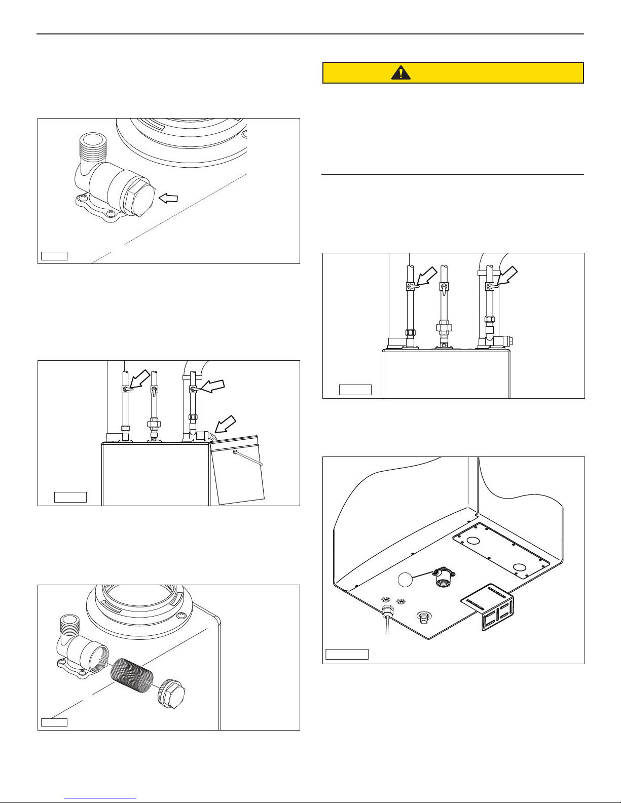
5. Maintenance
5.1 Cleaning the Inlet Water Strainer
All the water heaters are equipped with a sediment strainer
on the inlet water connection.
Initially, this strainer should be inspected and cleaned every
three months to establish a cleaning schedule.
IH-162
1. Turn off power and gas.
2. Position a container under the strainer on the water inlet
piping.
3. Close the water inlet and outlet valve (arrow) and remove
the cover plug. Allow the water to drain from the pipe.
5.2 Draining the Water Heater
CAUTION
Hot water can cause burns to the skin. The water
temperature is factory set to 120°F (49°C). To avoid burns,
make sure the water heater is OFF and the power supply is
disconnected. The water heater will remain hot for some
time. Wait until the unit has completely cooled before
draining the water heater or performing any other
maintenance.
1. Press the Power button to turn OFF the water heater.
Disconnect the power.
2. Close the water supply inlet and outlet valves. Turn OFF
the gas supply.
IQ-045
Note: If a water shut-off valve was not installed, shut off the
main water supply valve at the water heater.
4. Remove the strainer screen, clean it, and reinstall it in the
housing.
IQ-046
3. Position a bucket or other container against the drain port.
4. Use an Allen wrench and remove drain plug (1).
1
IQ-111
IH-162a
5. Replace the strainer cover plug.
5. When all the water has drained from the water heater,
replace the drain plug.
15 Maintenance Section

5.3 Filling the Water Heater
1. Open the water outlet supply valve. Slowly open the water
inlet supply valve.
2. Open the hot water faucet that is located farthest away
from the water heater. Once a steady stream of water
flows and all the air is purged from the system, close the
hot water faucet.
3. Connect the unit to the power supply.
4. Open a hot water faucet. The water heater should operate
normally.
Maintenance Section 16

6. Troubleshooting
6.1 Error Code Chart
Blower Speed Fault • Blower noisy / impeller jammed.
• Disconnected signal wire.
• Wiring faulty.
Blocked Flue Fault • Exhaust blocked (bird, etc).
• Backed up condensate.
• Wiring loose (switch open).
Ignition Failure • Water over-heat switch tripped.
• Faulty DSI, faulty igniter wire,
faulty ignition connection, faulty
PCB, bad igniter.
• Low gas pressure.
Temperature Sensor
Shorted
• Faulty sensor wiring
• Faulty sensor
• HE - heat exchanger water outlet
temperature sensor.
• FL - Flue temperature sensor.
• OA - outdoor air temperature
sensor.
• Faulty controller
• rE - Recirculation temperature
sensor.
• Ou - Domestic Hot water outlet
temperature sensor.
• Inspect blower / impeller. Clean and remove any
obstructions.
• Check PWN signal. Check for loose wires / pins, and
repair.
• Check PWN signal. Check for loose wires / pins, and
repair.
If the problem persists, turn control panel OFF, shut gas
valve, unplug unit, and contact an authorized service
technician.
• Check exhaust termination. Check exhaust
connection at water heater. Install screens.
• Check slope of drain. Check for double loops, air
locks, or debris in loop.
• Check wiring.
• Check pump, check cross over solenoid. Electrical
noise (dsi).
• Replace part.
• Adjust gas pressure at regulator, check / upsize gas
line, check for gas line blockage.
• If the problem persists, turn control panel OFF, shut
gas valve, unplug unit, and contact an authorized
service technician.
• Check for nicked or broken sensor wiring or
connectors. Also check for corroded or wet
connectors.
• Measure resistance of sensor at connector (18 Kohm
at 50°F, 10 Kohm at 77°F, 3 Kohm at 140°F)
• Replace controller
17 Troubleshooting

Temperature Sensor
Open Circuit
• Unplugged connectors
• Faulty sensor wiring
• Faulty sensor
• HE - heat exchanger water outlet
temperature sensor.
• FL - Flue temperature sensor.
• Faulty Controller
• rE - Recirculation temperature
sensor.
• Ou - Domestic Hot water outlet
temperature sensor.
• Check connectors and ensure they are securely
connected
• Check for nicked or broken sensor wiring or
connectors. Also check for corroded or wet
connectors
• Measure resistance of sensor at connector (18 Kohm
at 50°F, 10 Kohm at 77°F, 3 Kohm at 140°F)
• Replace controller
Flue Temperature
• Incorrect vent set up
Exceeded Set Limit
• High inlet temperature
• Faulty sensor wiring
• Faulty sensor
• Faulty Controller
Heat Exchanger Outlet
• Flow rate changes excessive
Temperature Exceeded
Set Limit
• Faulty sensor wiring
• Faulty sensor
• Faulty Controller
Flashing Icon • Indicates an error code and unit
locked out
Recirculation Icon
Flashing
• Pump inoperable
• Pump faulty & excessively hot
• Faulty Controller
• Plugged up solenoid valve
(P models)
• Solenoid valve faulty (P models)
• Jammed check valve
Init stays on display
• Faulty time valve/wiring • Replace time valve/wiring
• If vent pipe material is CPVC or Polypropylene, ensure
that CPVC is selected in the FP (Flue Pipe) mode.
• Ensure inlet temperature is lower than 150°F if vent
pipe material is PVC or lower than 190°F if vent pipe
material is CPVC or Polypropylene.
• Check for nicked or broken sensor wiring &
connectors. Also check for corroded or wet
connectors
• Measure resistance of sensor at connector (18 Kohm
at 50°F, 10 Kohm at 77°F, 3 Kohm at 140°F)
• Replace controller
• Ensure the water flow rate does not change faster
than 2 GPM every 5 seconds
• Check for nicked or broken sensor wiring or
connectors. Also check for corroded or wet
connectors
• Measure resistance of sensor at connector (18 Kohm
at 50°F, 10 Kohm at 77°F, 3 Kohm at 140°F)
• Replace controller
• Refer to the indicated error code (E1, E2, etc) for
resolution
• Check pump wiring harness for loose connectors
• Replace pump
• Replace controller
• Clean lines and replace solenoid
• Replace solenoid valve
• Remove check valve access and ensure gate is free to
move
Heat Exchanger never
• Solenoid valve faulty • Check solenoid (SMC) valve and replace if necessary
reaches set temperature
Troubleshooting 18

6.2 Wiring Diagram Chart
AIR SWITCH
GN
BOILER TT
RD
BL
YL
RD
CASCADING
CONNECTIONS
OFF
ON
AND FLOW SENSOR
WATER CONTROL VALVE
BN
WT
OR
BL
YL
GN
RD
GY
BL
WT
BL
RD
GN
OR
WIRE COLOR CODE
OUTDOOR TEMPERATURE SENSOR
BLUE
BROWN
BL
BN
INLET TEMP
COLD WATER
RED
GRAY
GREEN
ORANGE
RD
GY
OR
GN
WHITE
YELLOW
YL
WT
WT
TRANSFORMER
WT
3-cord cable
FUSE
RD
RD
BN
BN
FUSE
ON
NG
OFF
LP
FUEL SELECT
(POWER)
GREEN LED
RED LED
(BURNER ON)
BYBASS
ONLY
PUMP
VALVE
SOLENOID
BN
RD
LINE
NEUTRAL
GROUND
HEATING SYSTEM
PUMP TERMINAL
GY
FLUE TEMP
SENSORS
TEMPERATURE
BL
RD
WT
WT
OR
GN
IGNTER AND FLAME PROBE
WT
HIGH VOLTAGE CABLE
BN
BN
BN
BN
BL
OUTLET TEMP
F
FUSE
THERMAL
F
FUSE
THERMAL
OUTLET TEMP
BL
GAS
VALVE
BLOWER
19 Troubleshooting

6.3 Operational Diagram
Is
Program
?
time or
Thermostat
On?
?
?
?
?
?
?
IH-156
Troubleshooting 20

7. Serviceable Parts
7.1 Electrical Components
1
2
3
ITEM NO.
1
2
3
PART NUMBER
IGT-SPR0004
IGT-SPR0002
IGT-SPR0005
DESCRIPTION
DISPLAY
CONTROLLER
IGNITER MODULE
21 Serviceable Parts

7.2 Blower, Gas Valve, and Exhaust
2
4
3
ITEM NO.
1
2
3
4
1
PART NUMBER
IGT-SPR0017
IGT-SPR0016
IGT-SPR0008
IGT-SPR0011
DESCRIPTION
i20;/i250; FLUE PIPE ASSEMBLY (PP)
L;L;GAS INLET ASSEMBLY
BLOWER KIT
GAS VALVE KIT
Serviceable Parts 22

7.3 Water Lines and Fittings
2
15
5
12
21
16
1
11
18
19
20
7
8
4
3
1
13
21
6
14
9
17
ITEM NO.
1
2
3
4
5
6
7
8
9
10
11
12
13
14
15
16
17
18
19
20
21
10
PART NUMBER
IGT-SPR0036
IGT-SPR0018
IGT-SPR0024
WATER INLET FITTING (3/4" NPT)
HEAT EXCHANGER INLET TOP TUBE
IGT-SPR0023
IGT-SPR0003
IGT-SPR0025
IGT-SPR0026
HEAT EXCHANGER INLET BOTTOM TUBE
HEAT EXTANGER OUTLET TOP TUBE BUFFER
IGT-SPR0028
IGT-SPR0027
HEAT EXCHANGER OUTLET BOTTOM TUBE
IGT-SPR0029
IGT-SPR0031
IGT-SPR0032
IGT-SPR0033
PUMP TEE TO WATER OUT TUBE ASSEMBLY
PLATE HEAT EXCHANGER OUT TUBE
IGT-SPR0034
IGT-SPR0037
IGT-SPR0039
IGT-SPR0040
IGT-SPR0041
IGT-SPR0007
IGT-SPR0030
BUFFER TANK OUT TO WATER PUMP IN TUBE
IGT-SPR0062
1
DESCRIPTION
SMALL TEE
BY PASS TUBE
FLOW SENSOR KIT
TANK TO DRAIN PORT TUBE
DRAIN PORT
TEE BY-PASS LINE 2
TEE BY-PASS LINE 1
OUTLET PORT 3/4 NPT
2 PORT SOLENOID VALVE
PLATE HEAT EXCHANGER
ADAPTER 1/2 X 20 FEMALE
PUMP KIT
CLIP-ON SENSOR*
*Note: 1. Temperature outlet sensor is to be located just above SMC (#16) on outlet line (#12)
above bypass line.
2. Recirculation sensor is centrally located on the heat exchanger inlet bottom tube (#6).
23 Serviceable Parts

7.4 Ignition Components
2
1
ITEM NO.
1
2
Serviceable Parts 24
PART NUMBER
IGT-SPR0006
IGT-SPR0005
DESCRIPTION
ELECTRODE KIT
IGNITER MODULE

Multiple Units
8.
8.1 Modes of Operation
The Modes of Operation screens provide set up screens and
additional information on the water heater. There are five
Mode of Operation screens which are used by the technician
during installation or maintenance of the water heater.
8.1.1 Daisy Chain Mode
Press and release the Mode button until the desired screen
1.
shows on the display.
dC - Daisy Chain
2. Follow the instructions in the specific section to enter the
desired settings.
8.1.2 Common Exhaust Mode
1.
Press and hold the Mode button for five seconds until
the rS screen appears. Now press and release the Mode
button multiple times until the desired screen shows on
the display.
CE - Common Exhaust
2. Remove the front covers and locate the main circuit
boards on the first and last units.
3. Locate DIP Switch 3 on the first and last units and position
the switch in the ON position. On all the middle units,
position the switch in the OFF position.
ON
OFF
IN-61a
2. Follow the instructions in the specific section to enter the
desired settings.
8.2 Viewing and Setting Modes of Operation
8.2.1 Daisy Chain
Set DIP Switches
1. Disconnect the power from all the units in the system.
WARNING
SHOCK HAZARD
Before making any adjustments or connections inside the
water heater cabinet, make sure the power is disconnected.
Unplug the water and/or turn the circuit breaker OFF.
4. Using the supplied cables, connect one end of a cable
into either of two jack receptacles (arrows) located on the
circuit board and the other end to the jack in the next
unit.
i201X-i251X Multiple Units 25
IN-61

5. Pass the cable through the grommet located at the
bottom of the cabinet.
6. Secure the cable using a zip tie.
123
Dip Switch 3
ON
Dip Switch 3
OFF
Dip Switch 3
ON
IH-61a
7. Replace the front covers.
Set Up Unit Number
1. Reconnect the power and wait for the home screen to
appear.
8.1.2 Common Exhaust Mode
Changing this setting can only be done when the
Flame ON icon is not displayed.
This mode is applicable when multiple units are connected
together. Turning the CE mode ON allows multiple units
to be vented into a common vent. Refer to the Venting for
Commercial Application section for information on common
venting guidelines.
Press and hold the Mode button until the rS screen appears.
Press and release the Mode button multiple times until the
CE screen appears. The current setting will be displayed.
The default setting for this mode in ON.
2. Press and release the Mode button until the dC screen
appears. The designated number for the unit will be
displayed. The default is OFF.
3. Now, press the Up/Down arrows to select the desired
number for the particular water heater. Change the
selection from OFF to one of the ten possible selections
(01, 02, 03, though 05). The up/down arrows scroll from
OFF to 1 through 05 and then to OFF.
4. Once the desired number is selected, press and hold the
Enter button for three seconds to save this setting and
return to the main display screen.
5. Repeat the above steps and set each unit to a different
number. For example, the next unit would be 02, the
third unit would be 03, and so on.
Press the Up/Down arrows to select either ON or OFF.
Press the Enter button to save the changes and return to the
main display.
Note: If the Enter button is not pressed within 30 seconds of
inactivity, the display will return to the home screen.
26 i201X-i251X Multiple Units

9. Warranty
General
This unit is warranted by Intellihot Green Technologies Inc.
(Intellihot), and covers defects in materials and workmanship,
subject to the applicable time periods and terms below. The
warranty effective start date begins on the date of installation
or on the date of possession in the case of new construction.
This warranty is extended to the original purchaser and
any subsequent owner at the original install location, and
applies only when properly installed by a licensed contractor
and operated in accordance with the instruction manuals.
This warranty is limited to repairs or replacement of parts,
at Intellihot’s option that are proven to be defective under
normal use and connected only to potable water systems.
Shipping Costs
If a replacement part is supplied under the terms of this
warranty, Intellihot will provide ground service delivery for
the part free of charge. Any expedited shipping expense will
be paid by the customer.
Definition of Potable Water
Potable water is defined as drinkable water supplied from
utility or well water in compliance with EPA secondary
maximum contaminant levels (40 CFR part 143.3), as shown
in the table. Intellihot will warrant the heat exchanger coil
for hardness up to 15 Grains per gallon (257ppm as Calcium
carbonate).
Warranty Period
Residential Warranty: Heat Exchanger - 12 years, Other Parts 3 years, labor – 1 year
Commercial Warranty: Heat Exchanger - 6 years, Other Parts 3 year, labor – 1 year
Residential Domestic Hot Water (DHW) means potable water
heating in a single family residence. Commercial means all
other applications.
Heat Exchanger Coil
The warranty period for a heat exchanger coil failure,
when installed in a residential DHW application (including
recirculation), is twelve (12) years from the effective start date.
The warranty period for a heat exchanger coil, when installed
in a commercial application (including recirculation), is six (6)
years from the effective start date.
All other Parts and Components
The warranty period for any original parts (excluding the
heat exchanger coil) against failure, is three (3) years from the
effective start date. A replacement part will be warranted for
the unexpired term of the original warranty. Defective parts
submitted may not be returned. No returns will be accepted
without prior authorization from Intellihot.
Contaminant Level
Aluminum 0.05 to 0.2 mg/l
Chloride 250 mg/l
Color 15 color units
Copper 1.0 mg/l
Corrosivity Non-corrosive
Fluoride 2.0 mg/l
Foaming Agents 0.5 mg/l
Iron 0.3 mg/l
Manganese 0.05 mg/l
Odor 3 threshold odor number
pH 6.5-8.5 mg/l
Silver 0.1 mg/l
Sulfate 250 mg/l
Total dissolved solids (TDS) 500 mg/l
Zinc 5 mg/l
Labor
The applicable period of this limited labor warranty is one (1)
year from the effective start date. The payment and amount
of any payment are subject to approval at Intellihot’s sole
discretion. Replacement parts must be genuine Intellihot
parts and warranty service must be performed by a licensed
contractor. The Labor allowance will be paid based on the
following:
Repair or replacement of any parts - $75/hour up to
maximum of $150
Replacement of entire unit - $75/hour up to maximum of
$225
i201X - i251X Warranty 27

Not Covered by this Warranty
This warranty does not cover failures or problems due to:
• Failure to install in accordance applicable building codes,
ordinances, normal plumbing and electrical trade practices.
• Improper installation, improper use, improper maintenance,
improperly made replacements or repairs, accidents, or
abuse.
• Sediment deposits, fire, flood, lightning, freezing, and acts
of God, or any causes other than defects in materials and
workmanship.
This warranty will be void and have no effect if:
• The unit is modified or altered in any way.
• Appliance(s) or equipment attached to the unit, that have
not been approved by Intellihot Green Technologies.
• If the unit is used exclusively as a booster heater for a
commercial dishwasher, or if the water from a reverse
osmosis or deionized process is run directly through the
unit.
• The serial number is altered, defaced, or discarded.
Warranty Limitations
This warranty applies only when the unit is used in the United
States or Canada. Except for the limited warranties provided
above, Intellihot Green Technologies disclaims any and all
other warranties, including but not limited to warranties or
merchantability and fitness for a particular purpose; provided
however, that implied warranties or merchantability and
fitness for a particular purpose are not disclaimed during the
one year period from the effective date. Intellihot shall not be
liable for indirect, special, incidental, consequential, or other
similar damages, including lost profits, arising from or relating
to the unit. This warranty gives you specific legal rights, and
you may also have other rights which vary from state to state.
How to Make a Claim
Please call (877) 835-1705. Proof of purchase in the form of
a dated sales receipt and warranty registration is required in
order to obtain warranty service, and should be included
with your claim. The product owner should submit the
warranty claim directly to Intellihot at the following address:
Intellihot Green Technologies, Inc.
Attn: Warranty Claims
2900 W. Main Street
Galesburg, IL 61401
All parts claimed to be defective may be requested to be
returned to Intellihot for examination prior to full claim
settlement. Please include the following information on your
warranty claim:
• Model number and serial number of the unit.
• Date of original purchase.
• Owner’s name and address.
• A description of the problem with the part and unit.
28 Warranty

10. Product Warranty Card
To activate your warranty, please fill out the information
in the form below and mail to the following address:
Warranty Registration
Intellihot Green Technologies, Inc.
2900 W. Main Street
Galesburg, IL 61401
Model: __________________
Serial Numbers (up to 4):
________________________
________________________
________________________
________________________
Owner Information:
Name: _____________________________________________
Address: ___________________________________________
City, State, Postal Code _______________________________
Phone Number ______________________________________
Dealer Information:
Make a copy or cut here to remove page.
Sold By: ___________________________________________
Address: ___________________________________________
City, State, Postal Code _______________________________
Phone Number ______________________________________
29 Warranty Card


(Chauffe-eau automatique instantané à ventilation directe)
er Heater
y Preset
Wat
Factor
Natural Gas
(Réglage en usine pour gaz naturel)
Y PRESET FOR USE WITH
(POUR INSTALLATION À L'INTÉRIEUR SEULEMENT)
OR
CT
FA
PRÉRÉGLAGES D'USINE POUR UTILISATION AVEC
TUREL
NATURAL GAS
GAZ NA
ect-Vent Automatic Instantaneous
Dir
olt, 60 Hz, 5 Amps
FOR INDOOR INSTALLATION ONLY
120 V
Type of Gas
Input Rating
Maximum Inlet Gas Pressure: . . . . . . . . . . . .
(Pression de gaz d'arrivée maximum)
Minimum Inlet Gas Pressure: . . . . . . . . . . . .
(Pression de gaz d'arrivée minimum)
Minimum Inlet Gas Pressure (for adjustments): . .
(Pression de gaz d'arrivée minimum (pour ajustements))
Maximum Water Pressure: . . . . . . . . . . . . .
(Pression d'eau maximum)
Minimum
(Pression d'eau minimum)
Recovery Rating: . . . . . . . . . . . . . . . . . .
(Caractéristique de recouvrement)
Thermal Effi ciency / : Energy Factor:
(Efficacité thermique / Facteur énergétique)
NOx Emissions:
(Émissions de NOx)
(Pursuant to South Coast Air Quality Management District Rule 1
(conformément au règlement 1146.2 du "South Coast Air Quality Management District)
Top of heater
(Dessus du chauffe-eau)
Back of heater
(Arrière du chauffe-eau)
Front of heater
(Avantdu chauffe-eau)
Side (Côté)
Bottom of cabinet
(Côté canalisation)
: . . . . . . . . . . . . . . . .
: Btu/hr Maximu
(Type de gaz)
(Entrer le Classement)
Btu/hr Minimum . . .
. . . . . . . .
Water Pressure: . . . . . . . . . . . . .
. . . . . . . . . . . . . . . . . .
From Combustible
From
Minimum Clearances
(Dégagements minimums)
Non-Combustibles
(Des non-combustibles)
2 in (50.8 mm)
5/8 in (15.8 mm)
6 in (15.2 cm)
1/2 in (12.7 mm)
12 in (30.4 cm)
199,000
20,000
m . . .
13.0 W.C. (3.20 kPa)
8.0 W.C. (2.00 kPa)
8.0W. C. (2.00 kPa)
150 psi (1034 kPa)
15 psi (103 kPa)
265 GPH (1003 LPH)
Up to 98% / 0.94
(Jusqu'à 98 % / 0.94) (Jusqu'à 98 % / 0.94)
Less than 20 ppm
(Moins de 20 ppm)
146.2)
Construction
(D'une construction
combustible)
6 in (15.2 cm)
5/8 in (15.8 mm)
6 in (15.2 cm)
2 in (50.8 mm)
12 in (30.4 cm)
Intellihot Green Technologies Inc
2900 W. Main St.
Galesburg, IL 61401
info@intellihot.com
Phone: (877) 835- 1705
Email:
Web: www.intellihot.com
Serial Number:
(Numéro de série)
Dealer / Installer Contact Information:
Box if
Gas
Check
Converted to
Propane
Cocher la case si converti au gaz propane
ersion* to
Field Conv
opane Gas
Pr
(Conversion* sur place au gaz propane)
199,000
0
C. (2.62 kPa)
20,00
W.
10.5
C. (0.76 kPa)
C. (2.74 kPa)
3.0 W.
W.
11.0
150 psi (1034 kPa)
15 psi (103 kPa)
265 GPH (1003 LPH)
Up to 98% / 0.94
Less than 20 ppm
(Moins de 20 ppm)
*Refer to Installation and Operation
manual for conversion procedure.
(Se référer au manuel d'installation et
de fonctionnement pour la procédure de
conversion.)
(Collant ETL)
ETL STICKER
.
IGT-LBL-0005-01
Revised 02-2016
 Loading...