

Intelligent Weighing Technology Intell-Lab IL-0.0001 g, Intell-Lab PB-0.001 g, Intell-Lab PB-0.01g Service Manual
Page 1
A Higher Level of Precision…
A Higher Level of Performance
Intell-Lab™
IL 0.0001 g
PB 0.001 g
PB 0.01 g
Service Manual
Page 2

Page 3
Problem and solution for balances model IL-0.0001, PB-0.001 and PB-0.01g
Fau lt
Pos sible c a u se
Ser vice Ta b l e
Balance not stable.
Dirt inside the magnet.
Bandy flexures.
Mechanical group service.(Clear
the magnet)
Mechanical group
service.(change
Display doesn’t move from zero
Mechanical group damage
Error linearity
A/D converter fail
Mechanical group service
Function linearity
Check_main_board_signals_EM
C
Display doesn’t work correctly
Display damage
No power supply.
No connection display.
Change_display
Check_main_board_signals_EM
C
Keyboard fail/
At power on if balance beeps.
No connection keyboard
No bottom keyboard
Change cable 14 poli
Change keyboard
Corner load not correct
Parallelogram guide damage
Corner load not regulated
Change parallelogram guide
Corner load EMc
Linearity not correct
Regulated linearity error.
Verify bandy flexures
Function_linearity_
Mechanical group service
Page 4
Mechanical group service IL-0.0001, PB-0.001, PB-0.01g
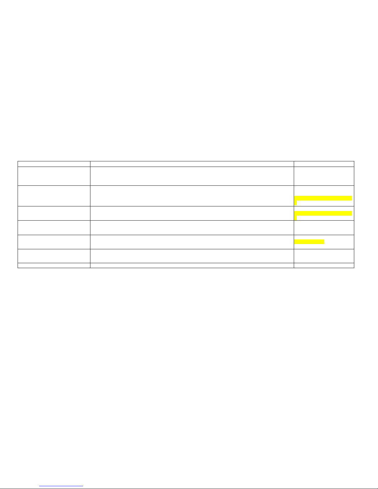
For Model IL0.0001
1. REMOVE THE BALANCE TOP COVER WITH DRAFTSHIELD (REMOVE ONE SCREW Fig.1 AND
FOUR SCREWS UNDER THE BALANCE Fig2
2. REMOVE THE COVER SHIELD OF MECHANICAL GROUP,
Fig.3
For Model PB-0.001
1. REMOVE THE BALANCE TOP COVER (REMOVE ONE SCREW Fig.1 AND FOUR SCREWS
UNDER THE BALANCE Fig2)
2. REMOVE THE COVER SHIELD OF MECHANICAL GROUP (REMOVE FOUR SCREWS Fig.3)
Fig.1
Fig.2
Fig.3
Fig.3
Page 5
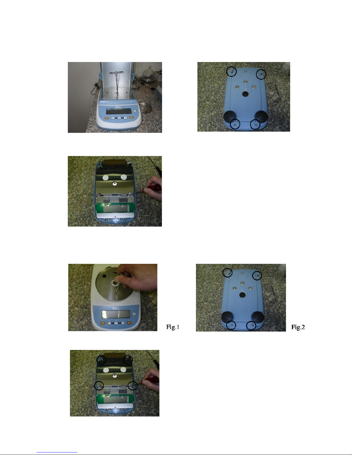
For Model PB-0.01
1. REMOVE THE BALANCE TOP COVER (REMOVE ONE SCREW Fig.1 AND FOUR SCREWS
UNDER THE BALANCE Fig2)
2. REMOVE THE COVER SHIELD OF MECHANICAL GROUP (REMOVE FOUR SCREWS
Fig.3)
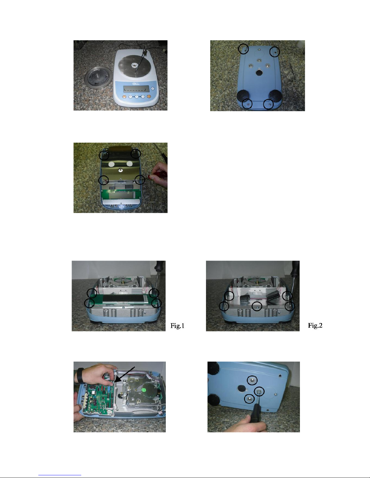
For all Model PB-0.01, PB-0.001, IL-0.0001
1. REMOVE THE DISPLAY BOARD (REMOVE FOUR SCREWS Fig.1) AND COVER SHIELD OF
MAINBOARD (REMOVE FIVE SCREWS Fig2)
2. REMOVE THE CABLE OF OPTICAL GROUP (Fig.3) AND THEN REMOVE THE MECHANICAL
GROUP (REMOVE THREE SCREWS UNDER THE BALANCE Fig.4)
Fig.1
Fig.2
Fig.3
Fig.3
Fig.4
Page 6
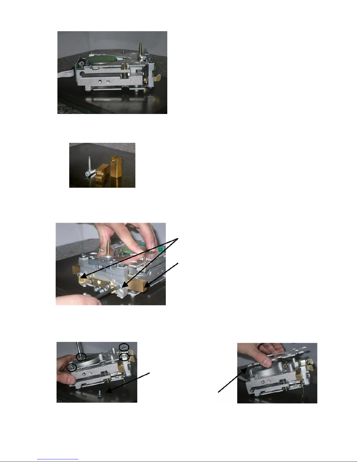
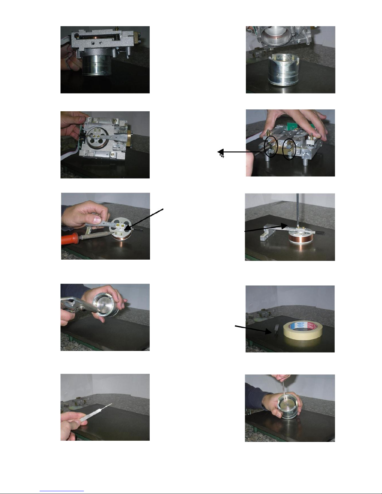
Disassembly group for all Model PB-0.01, PB-0.001, IL-0.0001
The mechanical group is the same for all model except for:
dimension of springs
dimension of spacers
cone
1. Take jigs for the moving pillar (two screws M5x20mm and two
spacers)
2. Insert the screws in the holes (left and right) of the
moving pillar
3. Insert the spacers in the space between moving pillar
and monobloc (left and right)
4. Fix the screws left and right
5. Turn up side down the group
6. Take tool n°7
7. Remove the four screws of
bottom parallelogram guide
9. Remove parallelogram,
handling it carefully
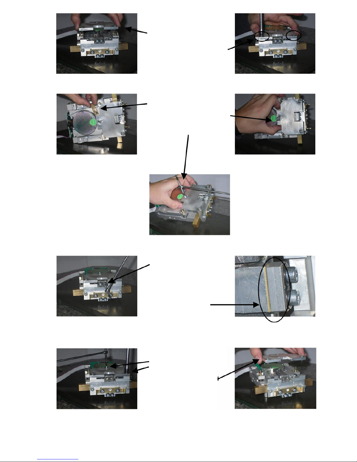
Page 7

9. Turn the group up
again
10. Remove the two
cone support’s
screws
11. Remove the cone
support
18. Take the jigs for vertical spring (n°2 screws M4x10mm, n°1
screw M4x22mm, n°1 clamping plate whit hole and n°1 tool to
fix the lever)
12. Take tool n°7
13. Remove the four
screws of top
parallelogram guide
15. Remove the top
parallelogram guide,
handle it carefully
17. Take tool n°7
17. Remove baricenter
from below the
monobloc
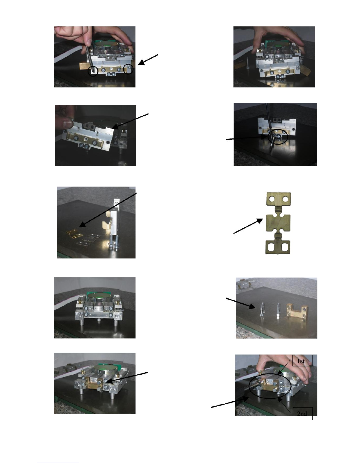
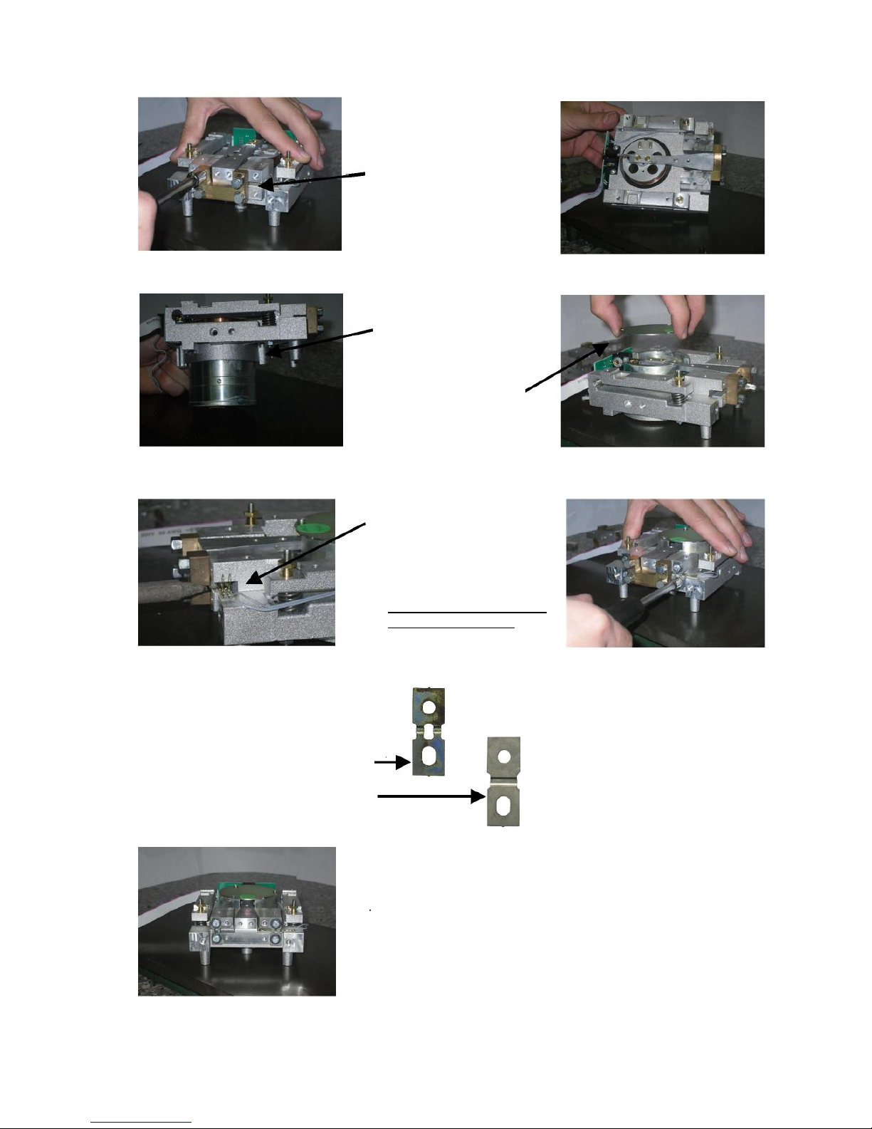
Page 8
19. Position the jig on the
moving pillar
20. Insert two screws in the
holes of moving pillar and
fix them.
21. Insert the clamping plate.
23. Insert screw and fix
clamping plate with tool
n °3.
24. Remove top screws of
vertical spring, with tool n°3
26. Remove spacer lever for:
0.0001g= n°1x7mm,n°1x0.5mm
0.001g = n°1x4mm.
0.01g = 0mm
27. Remove screw of plate.
28. Remove screws of fixed
to moving pillar.
30. Remove jigs for
vertical spring.
Page 9
29. Remove moving pillar
30. Remove screws of fixed
vertical spring with tool n°3
28. Remove the screws and
spacer fixed jigs of moving
pillar.
Spa cer of mov ing pi llar fo r:
0.0001g
= n°1x0.5mm
0.001g
= n°1x4mm
0.01g
= n°1x7mm, n°1x0.5mm
Ver tic al spri ng:
0.0001g = Vertical spring 0.5/0.10mm
0.001g = Vertical spring 0.5/0.10mm
0.01g = Vertical spring 1/0.12mm
31. Take jigs for the lever (n°4
screws M4x19mm, n°1 tool
for fixing the lever)
33. Put the jig on the lever
34. Insert two screws in
to monobloc and two in
to lever.
35. Fix the screws: first
the top ones then the
bottom ones
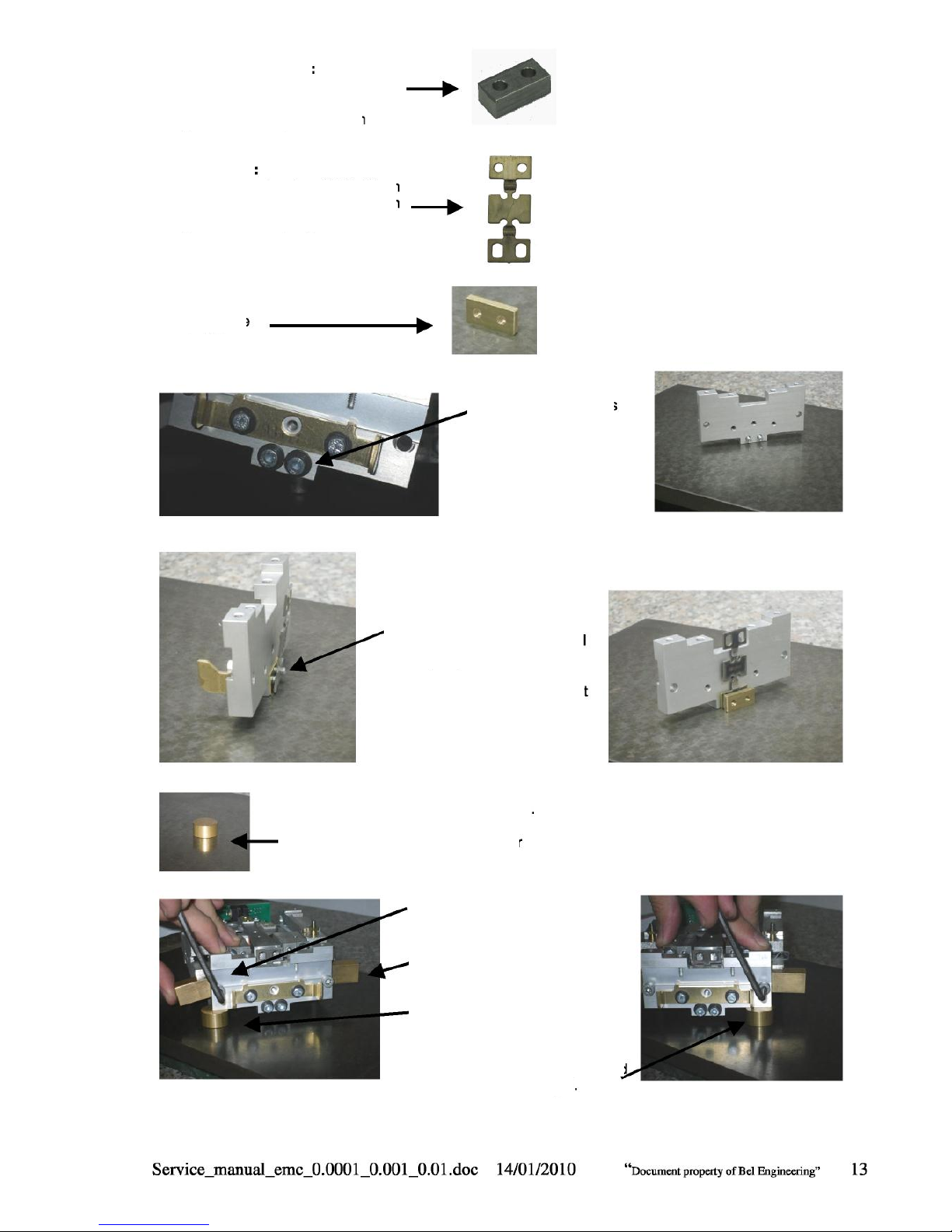
Page 10
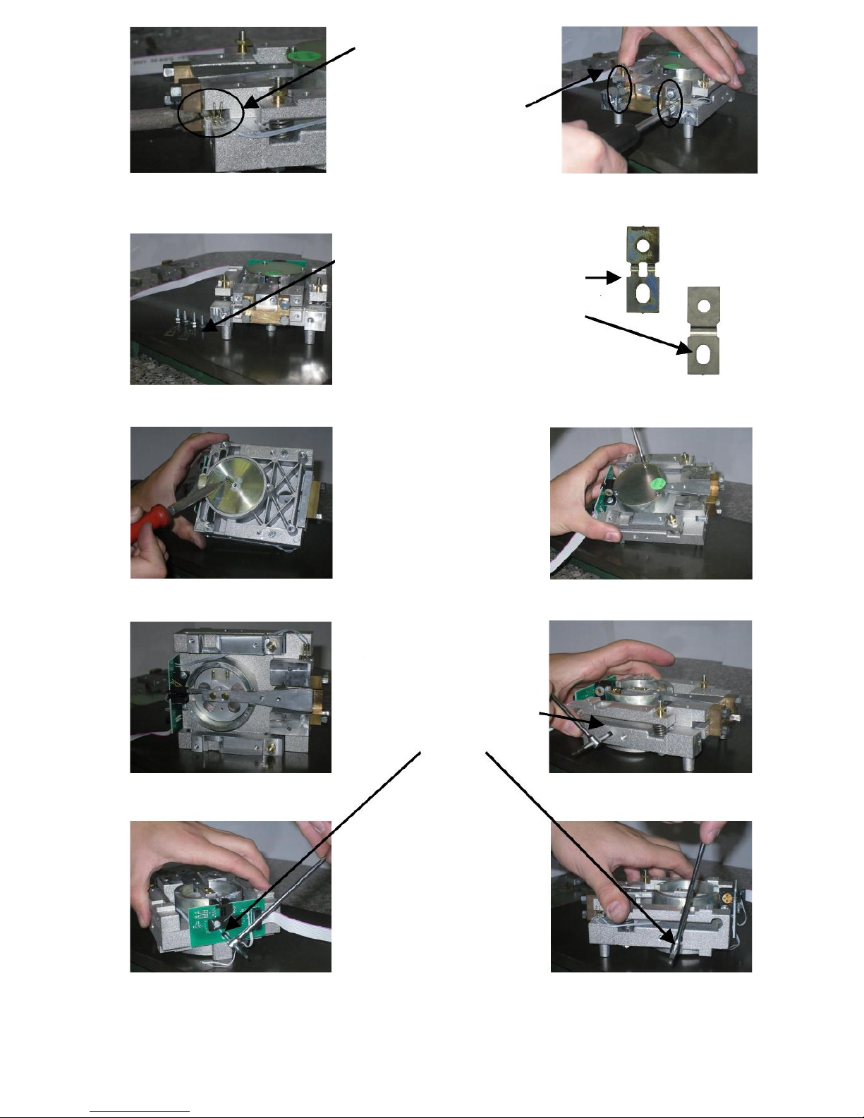
38. Unsolder the wire of
sensor
39. Remove n°3 screws that
fix the magnet cover
35. Unsolder the gold wires.
36. Remove n°4 screws that
the fulcrum flexures using
tool n°7.
38. Remove the fulcrum
flexures
Ful cru m fl exu res :
0.0001g = Fulcrum flexures 0.5/0.09mm
0.001g = Fulcrum flexures 0.5/0.09mm
0.01g = Fulcrum flexures 0.51/0.10mm
40. Remove magnet cover.
42. Remove n°5 grains (n°2
left and rigth side and n
°1 at rear side) that fix
the magnet.
Page 11
42. Remove magnet from
below the monobloc
C. Unsolder the wire of
coil.
D. Remove n°2 screws and
spacer of coil that fix the
lever to coil.
43. Clean the magnet with
air
44. Take a taper and
precision tweezer.
45. Put taper on the top of
precision tweezer so
that adhesive side is
outside.
46. Clean deeply the
magnet turning
precision tweezer
around of magnet.
Now if you need to remove the
lever to change the coil or lever
then follow points from A to E,
otherwise go to point 43.
A. Remove jigs for
lever (Remove n
screws).
C. Remove the lever.
Page 12
Now you can start assemble the mechanical group
47. Take jigs for level (n°4
screws M4x19mm, n°1
tool for fixing the lever).
48. Insert two screws in to
monobloc and two in to
lever.
49. Insert magnet from
below into monobloc
50. Put on the cover of
magnet (do not fix it).
Ful cru m fl exu res :
0.0001g = Fulcrum flexures 0.5/0.09mm
0.001g = Fulcrum flexures 0.5/0.09mm
0.01g = Fulcrum flexures 0.51/0.10mm
51. Solder the gold wires on
the lever.
52. Put fulcrum flexures with
four screws, and fix
them.(Position the flexures
with circular hole UP)
54. Remove the jig for the
Page 13
57. Take the jig for the vertical spring.
59. Take jig spacer for moving pillar
61. Insert screws in the holes
(left and right) of moving
pillar
62. Insert spacer between
moving pillar and monobloc
(left and right)
63. Put the jig spacer under the
left side of moving pillar and
fix the screw on left.
64. Put the jig spacer under the
right side of moving pillar and
fix the screw on right.
Clamping plate
54. Insert two screws
(M4x22mm) with
washer.
55. Insert the spacer on
moving pillar, and vertical
spring
57. Insert Clamping plate, but
do not strongly fix the
screws.
Spacer movin pill ar for:
0.0001g
= n°1x0.5mm
0.001g
= n°1x4mm
0.01g
= n°1x7mm, n°1x0.5mm
Vertical spring:
0.0001g
= Vertical spring
0.5/0.10mm
0.001g
= Vertical spring
0.5/0.10mm
0.01g
= Vertical spring
1/0.12mm
Page 14

66. Center the hole of the
vertical spring with the hole
of the lever.
68. Fix the two screws of
bottom vertical spring
70. Insert spacer of lever for:
0.0001 g=n °1 x7mm,n °1 x0.5mm
0.001g = n°1x4mm.
0.01g = 0mm
71. Insert top screws of vertical
spring, and fix them using
tool n°3
73. Remove the cover of
magnet
75. Insert jigs for centering the
lever
77. Fix the screws of coil.
79. Remove the screw that fix
the clamping plate of jig.
81. Remove screws that fix the
jig for vertical spring.
83. Remove jig for vertical
spring.
63. Put the top parallelogram
guide onto the group.
64. Insert the jigs for
centering the
parallelograms
65. Insert four top screws of
parallelogram guide and fix
them.
Page 15
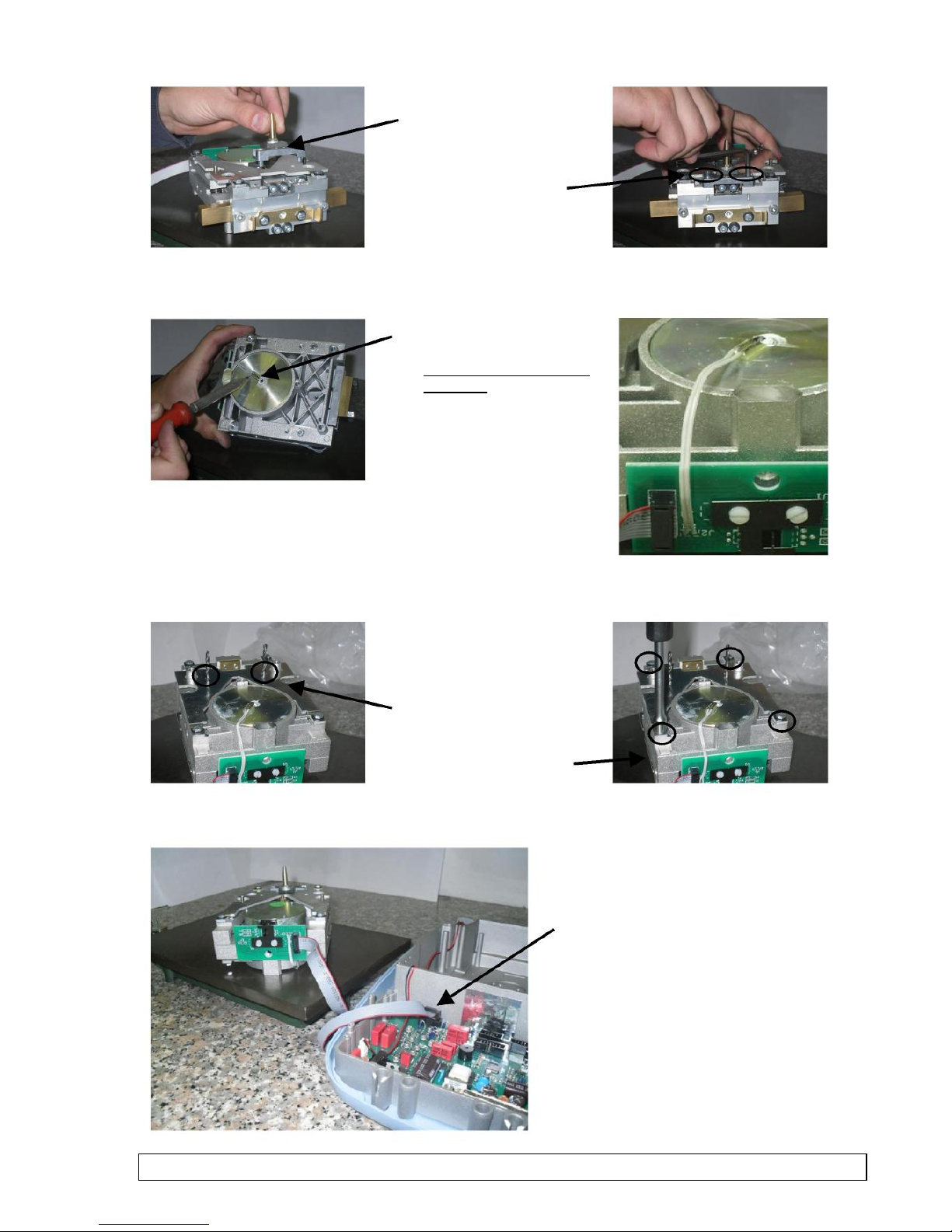
79. Put the bottom
parallelogram guide on
bottom of the group.
81. Insert the jigs for
centering parallelograms
83. Insert four screws of
parallelogram guide and fix
85. Turn up the group
87. Connect the group to the main board.
76. Put cone support on the
moving pillar
78. Insert two cone support’s
Screws and fix them
80. Solder the wire of
temperature sensor.
(Im por tan t: do not invert
the wires)
Page 16

Aut o c ali bra tion sys tem mo tor gr oup
84. Turn on the balance and center the lever. (when the
balance is turned on, the lever must exactly be
centered in the window).
85. Fix the screws
86. Fix the mechanical group in the bottom case.
87. Check the main board signals.
88. Regulate the corner load error of the balance.
89. Check and regulate linearity of balance.
Page 17

Corner load regulation for model EMC IL-0.0001, PB-0.001, PB-
0.01g
For Model IL-0.0001
1. REMOVE THE COVER WITH DRAFTSHIELD (REMOVE ONE SCREW Fig.1 AND FOUR
SCREWS UNDER THE BALANCE Fig2)
2. REMOVE LABELS ON THE HOLES (Fig 3)
3. CONNECT KEYBOARD, PUT THE PLATE WIHT WINDSHIELD AND TURN ON THE
BALANCE. (KEEP WARM UP FOR 20 MINUTES Fig 4.)
Fig.3
Fig.4
Page 18

For Model PM-0.001
1. REMOVE THE CAPS (Fig.5)
2. PUT THE PLATE AND TURN ON THE BALANCE. (KEEP WARM UP FOR 20 MINUTES.)
For Model M0.01
1. REMOVE DISK UNDER THE PLATE.(REMOVE FOUR SCREWS Fig.6)
2. PUT THE PLATE AND TURN ON THE BALANCE. (KEEP WARM UP FOR 20 MINUTES.)
For all Model PB-0.01, PB-0.001, IL-0.0001
TOOL NUMBER 8
FOR CORNER LOAD RAGULATION SCREW FOR CORNER LOAD REGULATION
Fig.5
Fig.6
Page 19

1. PUT THE WEIGHT (1/3 OF MAX RANGE) TO CHECK IN THE CENTER OF THE PLATE, AND
PRESS TARE.
2. MOVE THE WEIGHT IN THE POINT 2A, READ AND WRITE DOWN THE VALUE.
3. MOVE THE WEIGHT IN THE CENTER AND PRESS TARE.
4. MOVE THE WEIGHT IN THE POINT 2B, READ AND WRITE DOWN THE VALUE.
5. TAKE THE TOOL AND REGULATE AS ILLUSTRATED IN THE TABLE BELOW
IF THE CORNER 2A POSIT IVE(+) THEN
TURN THE TOOL CLOCKWISE
(SCREW A)
IF THE CORNER 2A NEGATIVE(-) THEN
TURN THE TOOL ANTICLOCKWISE
(SCREW A)
IF THE CORNER 2B POSITIVE(+) THEN
TURN THE TOOL ANTICLOCKWISE
(SCREW B)
IF THE CORNER 2B NEGATIVE(-) THEN
TURN THE TOOL CLOCKWISE
(SCREW B)
Attention: if the corner opposite can not corrected, check if the mechanical group is ok.
Page 20

PROCEDURE TO LINEARIZE EMC BALANCES IL-0.0001, PB-
0.001, PB-0.01g RELEASE R2.xx
For model with four point of linearity
1.
2.
3.
4.
5.
6.
Switch on balance.
After 30 min press ON/OFF button.
Press sequentially buttons ON/OFF - CAL – CAL.
You will see "Lin" on display, press ENTER to confirm..
The display shows on the left number “1” wait stability and after 3 seconds press CAL to confirm.
When the balance and show number 2 on the left put first weight, (table weight for linearity) wait
stability and after 3 seconds press CAL to confirm.
Put second weight, wait stability and after 3 seconds press CAL to confirm.
Put third weight, wait stability and after 3 seconds press CAL to confirm.
After this point, press CAL and keep it pressed until the display show number 3 on the left.
Then press ON/OFF to return to weighing mode.
Calibrated the balance and check linearity.
Attention: if you forget point 9 the data will not be stored and you will have to do again the
linearization procedure.
For model with seven point of linearity
Switch on balance.
After 30 min press ON/OFF button.
Press sequentially buttons ON/OFF - CAL – CAL.
You will see "Lin" on display, press ENTER to confirm..
The display shows on the left number “1” wait stability and after 3 seconds press CAL to confirm.
When the balance and show number 2 on the left put first weight, (table weight for linearity) wait
stability and after 3 seconds press CAL to confirm.
Put second weight, wait stability and after 3 seconds press CAL to
confirm. Put third weight, wait stability and after 3 seconds press CAL
to confirm. Put fourth weight, wait stability and after 3 seconds press
CAL to confirm. Put fifth weight, wait stability and after 3 seconds
press CAL to confirm. Put sixth weight, wait stability and after 3
seconds press CAL to confirm.
After this point, press CAL and keep it pressed until the display show number 3 on the
left. Then press ON/OFF to return to weighing mode.
Calibrated the balance and check linearity.
Attention: if you forget point 9 the data will not be stored and you will have to do again the
linearization procedure.
For model with twelve point of linearity
Switch on balance.
After 30 min press ON/OFF button.
Press sequentially buttons ON/OFF - CAL – CAL.
You will see "Lin" on display, press ENTER to confirm..
The display show on the left number “1” wait stability and after 3 seconds press CAL to confirm.
When the balance and show number 2 on the left put first weight, (table weight for linearity) wait
stability and after 3 seconds press CAL to confirm.
Put second weight, wait stability and after 3 seconds press CAL to
confirm. Put third weight, wait stability and after 3 seconds press CAL
to confirm. Put fourth weight, wait stability and after 3 seconds press
CAL to confirm. Put fifth weight, wait stability and after 3 seconds press
CAL to confirm. Put sixth weight, wait stability and after 3 seconds
press CAL to confirm. Put seventh weight, wait stability and after 3
seconds press CAL to confirm. Put eighth weight, wait stability and after
3 seconds press CAL to confirm. Put ninth weight, wait stability and
after 3 seconds press CAL to confirm. Put tenth weight, wait stability
and after 3 seconds press CAL to confirm. Put eleventh weight, wait
stability and after 3 seconds press CAL to confirm. Put twelfth weight,
wait stability and after 3 seconds press CAL to confirm.
The balance goes automatically in stand-by status ; press ON/OFF to return to weighing mode.
Calibrated the balance and check linearity.
1.
2.
3.
4.
5.
6.
7.
8.
9.
10.
11.
12.
13.
14.
15.
1.
2.
3.
4.
5.
6.
7.
8.
9.
10.
11.
12.
13.
14.
15.
16.
17.
18.
19.
Page 21

Clear the linearity and calibration value:
1. Switch on balance.
2. Press sequentially buttons ON/OFF - CAL – CAL.
3. You will see "Lin" on display, press ENTER to confirm..
4. The display show on the left number “1 ” press MENU and keep it pressed until the display shows
CLEAR.
Page 22

Page 23

Page 24

MARK "M " 0.0110.l g
ODOIO
E
MORELLO
PORTATA(
RISOLUZ.4gti
L.inearita'fpBsi lassB FL
S
22C LCCC
v. v v.'
v - v v vv V ^ y
'./LC 2D
v.v v.'
C-' EC 3CC EC
-.
C-'KC g -3CCc -ELCCc
'./ 2 C 2 D
E2CC
-,
B _ " I'
i2 v2 C
u
v. v.
„ „u - 2vu uu - 3v uuu -v u uu -uv uu u -u v uc
6_= =
`.:'2 v v20
22v 2vvv
v.v v.'
v v 2vvv '?v
-.
C-' E CCg- 3 =c-L ECCc
BL___-
V55 C2 0
„ ' CC -3 CC -.E-,LCC
BL fE
VE2C2O
E2CC
C. v.'
u ?u"u 'L 2~vuu 32vuu ~vuuu ~?vu~
6L- '.E2
`.'v2v2C
V V V
. .,v g-2CCC -3CCCc-LCCCc - E C C Cc -6
TOP RAY 0.00l g
=D I C E
MODE LLO
PORTATA4g;
RISOLUZ.g }
Lin~arita' fpEei
Sa :a
D_r
TOP RAY
v.--
Page 25

Internal calibration
In these balance models there are 4 calibration modes:
From display zero condition, press and keep pressed the MENU button until the acoustic
alarm is over, then release the button. The message “unitS” will be visualized on display,
press then MENU button until you visualize “Calib” on display. Press PRINT to confirm.
1. Select the calibration mode you wish by pressing MENU button in sequence:
AUT-CAL: auto calibration
I-CAL: internal calibration
E-CAL: external calibration
TEC-CAL: technical calibration
2. Press PRINT button to confirm “AUT-CAL”, “I-CAL”, “E-CAL”. To confirm “TECCAL” keep pressed the PRINT button until the acoustic alarm is over.
3. After selection, the balance returns to calibration menu. Press and keep pressed
MENU button until the acoustic alarm is over, then release the button. Balance is again
ready for weighing operations.
Technical calibration (TEC-CAL)
This function allows to store the value of internal reference mass whenever checking or
assistance actions require it.
1. After having selected the TEC-CAL calibration mode, press CAL button at empty pan. It
will be displayed “CAL”.
2. When the value of calibration weight start flashing on display, load the weight on to the
balance pan.
3. Wait the acoustic alarm and that the displayed calibrated weight value stops flashing,
then unload the weight from balance pan.
4. When string “0.000” is displayed continuously, then press and keep pressed the PRINT
button. This starts the internal weight value automatic acquisition and store. During the
acquisition cycle,
Page 26

the display will show “TEC-MEM”.
5. After having stored the value of internal calibration weight, balance returns to normal
weighing conditions.
6. Return to calibration menu as described at paragraph 6.2 and set the desired
calibration mode: internal, automatic or external..
ATTENTION : this procedure must be effected only using E2-class reference masses.
Page 27

Change main board EMC series IL-0.0001, PB-0.001, PB-0.01g
1. REMOVE THE COVER OF BALANCE.(REMOVE THE SCREW ON THE TOP, AND
FOUR SCREWS ON THE BOTTOM.
2. REMOVE THE DISPLAY AND THE BOARD SHIELD.
3. DISCONNECT POWER SUPPLY, OPTICAL SENSOR CONNECTOR, RS232
CONNECTOR, KEYBOARD CONNECTOR, DISPLAY CONNECTOR, GEAR
CONNECTOR, AND UNSOLDER SIGNAL RESISTOR.
4. REMOVE SCREWS FIXED MAIN BOARD AND SINK.
Page 28

NOW YOU CAN ASSEMBLE THE NEW MAIN BOARD.
5. CONNECT, POWER SUPPLY, OPTICAL SENSOR, RS232, KEYBOARD,
DISPLAY, GEAR CONNECTOR AND SOLD SIGNAL RESISTOR.
6. FIX THE DISPLAY AND THE BOARD SHIELD.
7. FIX THE COVER OF BALANCE.
8. CHECK AND REGULATE CALIBRATION LINEARITY AND INTERNAL
CALIBRATION(TECH CAL).
IMPORTANT: When you order a new MAIN BOARD, please tell us the reference code printed on label on board shield (fig.1)
Page 29

Check of main board signals EMC series IL-0.0001, PB-0.001, PB-0.01g.
Tp2
AGND
Tp7
Reference 5V
Tp4
- 12 V
Tp3
+ 12
Tp1
DG
Tp5
+ 5
Signal Resistor
Tp 8
From –2,4V
(with unload
plate)
To +2,4V
(with
maximum
range on
plate)
Power
24 v AC
Keyboard Connector
Gear
connector
Tp 6
+ 3.3 V
Display
RS232
Connector
Page 30

Spare parts for balance EMC model IL-0.0001, PB-0.001,PB-
0.01g
Page 31

M0.0001g/M0.0001ig
CODE
DESCR IP TION
IMAGE
A7 13
A7 12
A7 11
ALLUMINIUM INTERNAL CASE
MECHANICAL GROUP SHIELD
MAIN BOARD SHIELD
ADJUSTABLE FEET PLASTIC CASE
HOOK CAP
DUST COVER ANALITICAL
LEVEL BUBBLE
KEYBOARD BEL ADT7 124
MAIN BOARD BILMSP430_427_REV2.1
ANALITICAL
A73 1
A503
A720
S3 14
S284
S304
OPTICAL SENSOR
DISPLAY BOARD
DISP_LCD_ADT7 1 24_REV 1.1
A7 19
A538
Page 32

Page 33

Page 34

Page 35

ONLY M0.0001ig
CO DE
DESC RIPTION
IMAG E
M642
INTERNAL WEIGTH 200g
Page 36

PB-0.001 g / PB-0.001 g
Page 37

PB-0.001 g / PB-0.001 g
CO DE DESCRI PTION IMAG E
A712 MECHANICAL GROUP SHIELD
A7 11
A7 13
A503
S3 13
MAIN BOARD SHIELD
ALLUMINIUM INTERNAL CASE
LEVEL BUBBLE
MAIN BOARD MSP430_427_REV2.1 6K
S284
S304
E3 18
S310
OPTICAL SENSOR
DISPLAY BOARD
DISP_LCD_ADT7 1 24_REV 1.1
LCD ADT7 124
CABLE 14 PIN FOR KEY CONNECTING
S3 11
CABLE 26 PIN FOR DISPLAY
CONNECTING
Page 38

M0.001g/M0.001ig
CO DE DESCRI PTION IMAG E
A720 KEYBOARD BEL ADT7 124
E493
E748
E496
M620
CABLE WITH DC PLUG
CABLE WITH RS232 CONNECTOR
CABLE WITH SENSOR TEMPERATURE
MONOBLOC
M109
LEVER WITH FLAG
M9 12
COIL
M20 1
MOVING PILLAR
Page 39

Page 40

Page 41

Page 42

Page 43

M0.01g/M0.01ig
A713 ALLUMINIUM INTERNAL CASE
A503
S3 13
LEVEL BUBBLE
MAIN BOARD MSP430_427_REV2.1
6K
S284
OPTICAL SENSOR
S304
E3 18
S310
S3 11
A720
DISPLAY BOARD
DISP_LCD_ADT7 1 24_REV 1.1
LCD ADT7 124
CABLE 14 PIN FOR KEY
CONNECTING
CABLE 26 PIN FOR DISPLAY
CONNECTING
KEYBOARD BEL ADT7 124
CABLE WITH DC PLUG
E493
CABLE WITH RS232 CONNECTOR
E748
Page 44

TEMPERATURE
M620
M109
M9 12
MONOBLOC
LEVER WITH FLAG
COIL
M20 1
MOVING PILLAR
M053
M054
MAGNETIC GROUP
COVER MAGNET
Page 45

Page 46

Page 47

ONLY M0.01ig
CO DE
DESC RIPTION
IMAG E
M641
INTERNAL WEIGHT 400g
M642
INTERNAL WEIGTH 200g
 Loading...