

Page 1

1
MAINTENANCE MANUAL
AM WEIGHING SCALE SERIES
MODELS: AM-3000, AM-6000, AM-15K, AM-30K
CONTENTS
1. INTRODUCTION
2. SPECIFICATIONS
2.1 SYSTEM BLOCK DIAGRAM
2.2 PHYSICAL LAYOUT OF ELECTRICAL CONNECTION
2.3 GENERAL SPECIFICATIONS
3. INITIAL SETUP
3.1 INTERNAL FUNCTION AND SETTING METHODS
3.2 AUTO AND DEALER CALIBRATION PROCEDURES
3.3 DISABLE CALIBRATION WITH DIP SW.(S1)
3.4 OFFSET AND SPAN VALUE DATA
3.5 FLOW CHART
4. TROUBLE SHOOTING
4.1 TROUBLE SHOOTING LOOP
4.2 PARTS AND COMPONENTS TROUBLE SHOOTING
5. ELECTRICAL CIRCUITRY
5.1 SCHEMATICS
5.2 PCB LAYOUT
6. BILL OF MATERIAL
7. APPENDIX
DECEMBER 1999 REV 1
Specifications and Function Subject to Change without Notice
Page 2

2
1. INTRODUCTION
AM SERIES - ELECTRONIC WEIGHING SCALE
FEATURES:
* Full Tare
* Tare Indicator
* Zero Indicator
* Negative Value Indicator
* 2 Types of Calibration
* Dip Switch to prevent end-user calibration
* Sealable
* Bubble Level
* Adjustable Feet
* 5 1/2 x 25mm Wide Angle LCD Display
* Long Battery Operating Time
* Low -battery Indicator & Charge Indicator
* Auto Power Saving Function
* Dual Power: By Built -in Recharge
able Battery or Power Adaptor
* Platter with Stainless Steel Insert
* Optional Backlighting
* Optional Secondary Pole Mount Display
* Optional Rear Display
* Optional RS-232C Interface
* Ove rload protection against positive and negative force
* Capacity: 3kg,6kg,15kg,30kg for 1/3000 resolution
Page 3
3
2. SPECIFICATION
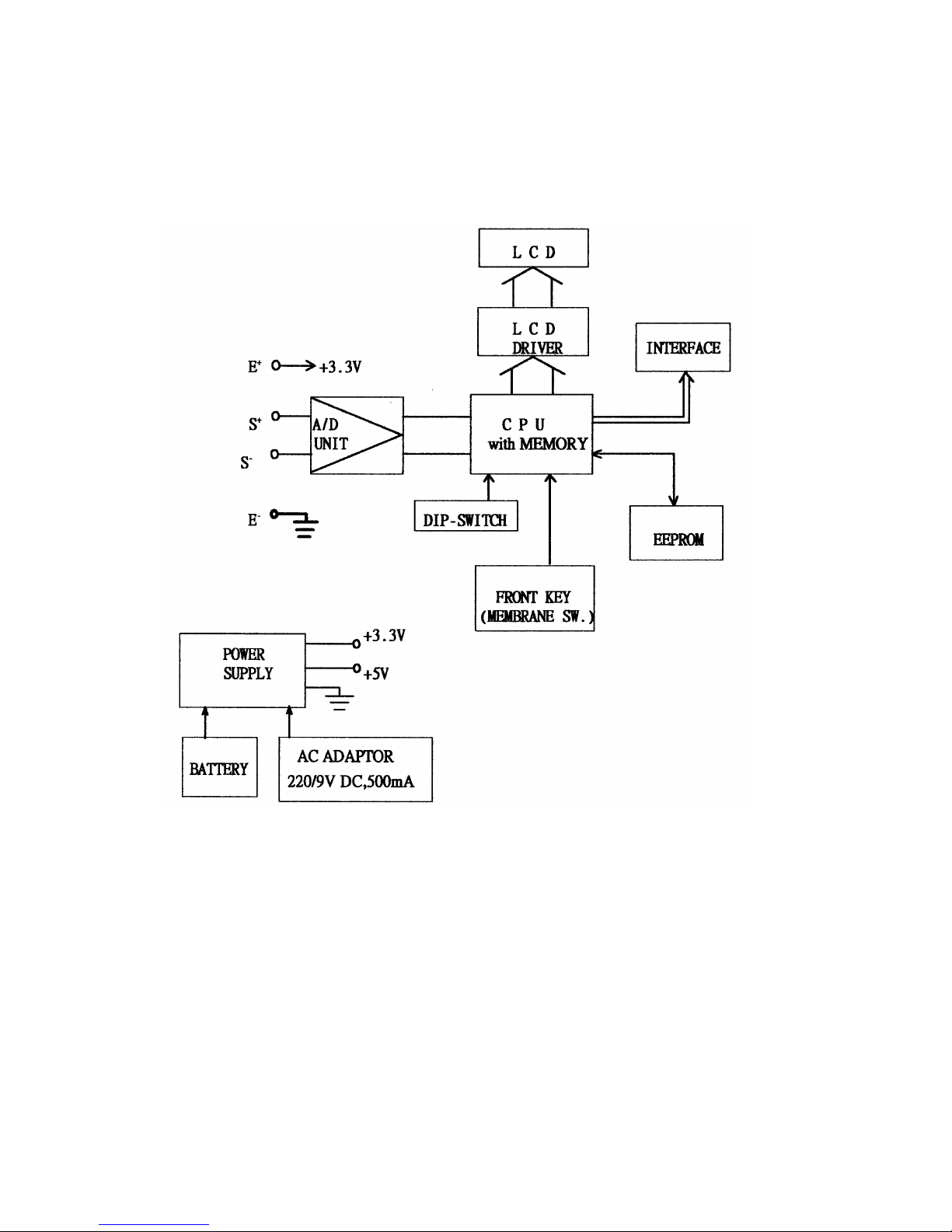
2.1 SYSTEM BLOCK DIAGRAM
DESCRIPTION:
When a load is applied to the loa d cell. The resistance to the excitation
current in the strain gauge changes and the analog output signal varies.
It is amplified and digitalized continuously by the A/D converter into
a digital signal.
Subsequently, the resulting count is processed and managed by the CPU.
The CPU refers to the instructions from the keyboard, and then conveys
the output data to LCD driver which formats the data into a readout
for the display.
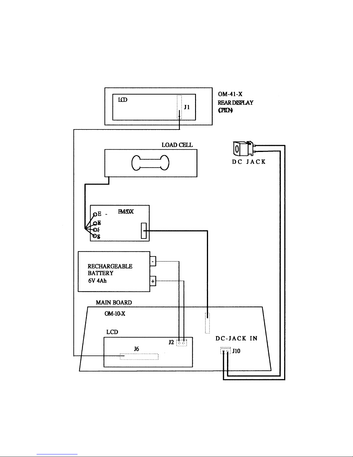
2.2 PHYSICAL LAYOUT OF ELECTRICAL CONNECTION
Page 4
4
Page 5
5
2.3 GENERAL SPECIFICATION
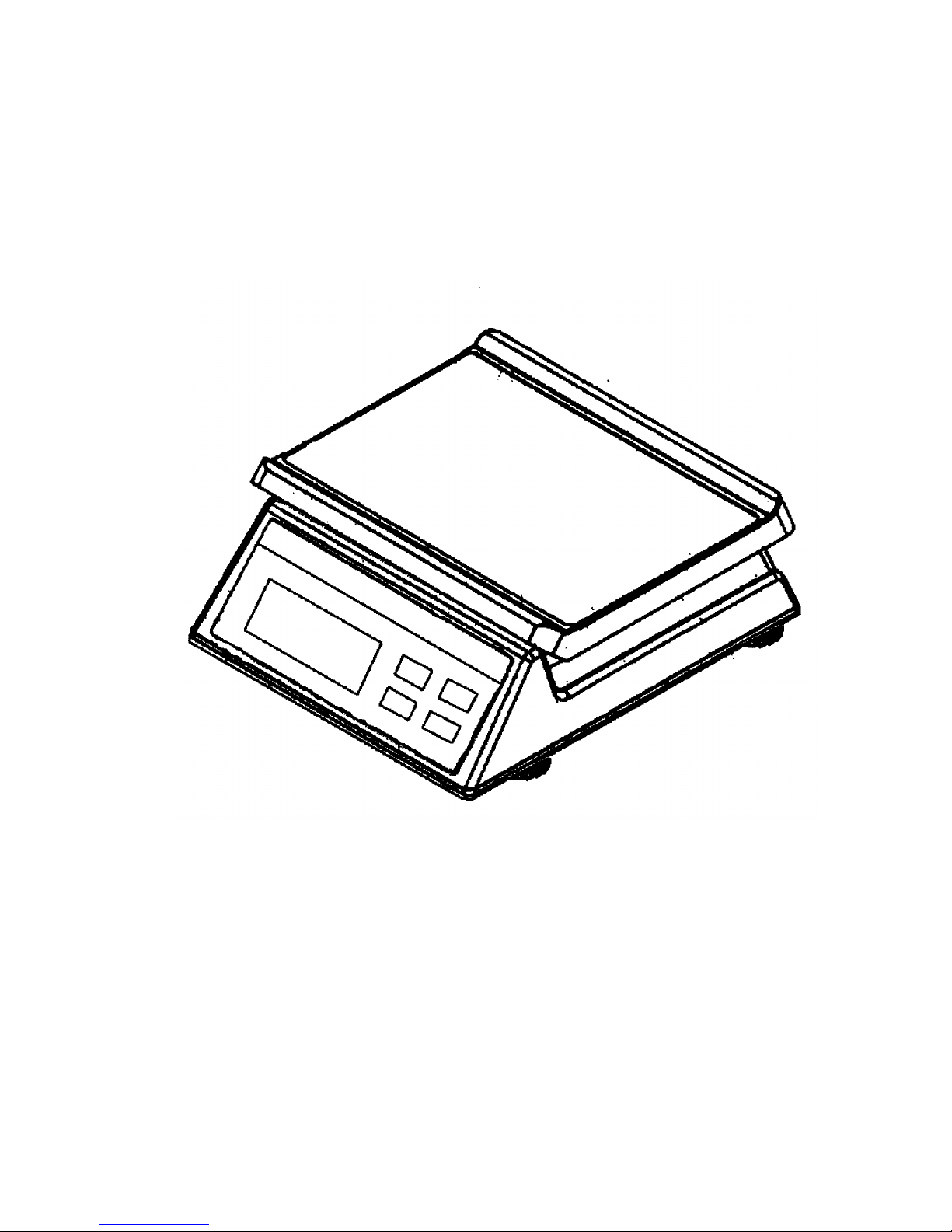
2.3.1 Overall View
2.3.2 Dimension
* Platter size: 245 x 300mm
* Overall size: 336 x 285 x 118mm
2.3.3 Model specification
Model name: AM series
Display resolution: 1/3000(3kg,6K,15kg,30kg)
Internal resolution: 1/30000
Display: Single-sided,Double-sided if request
Weight display--> 5 digits
2.3.4 Operation condition
* Power source: Rechargeable battery(6V 4Ah) or AC power
adaptor(220V/9V DC,500mA)
Page 6

6
* Operating Temperature : 0¢C ~ 40¢C
* Operating Humidity : 15 ~ 85% RH
* Power Consumption : 0.1W
5W When charge
2.3.5 Main Components used
* Micro Processor : 89C51
* Crystal Oscillator : 6 MHz
* Display device : Liquid Crystal Display(LCD)
* Loadcell : 350 resistance loadcell
2.3.6 Analog Specification
* INPUT SENSITIVITY : 2mV/V(C2G1 TYPE LOAD CELL)
* ZERO ADJUST RANGE : 2% R.O.
* ZERO BALANCE RANGE : +/-10% R.O.
* L/C APPLIED VOLTAGE : DC 3.3V
* SPEED OF A/D CONVERSION : 10 times/sec
* INTERNAL RESOLUTION : 30000
2.3.7 Model VS. Capacity & division
MODEL NO. CAPACITY EXTERNAL DIVISION
1/3000
AM-3000 3kg 1g
AM-6000 6kg 2g
AM-15K 15kg 5g
AM-30K 30kg 10g
Page 7
7
3. INITIAL SETUP
3.1 INTERNAL FUNCTIONS AND SETTING METHODS
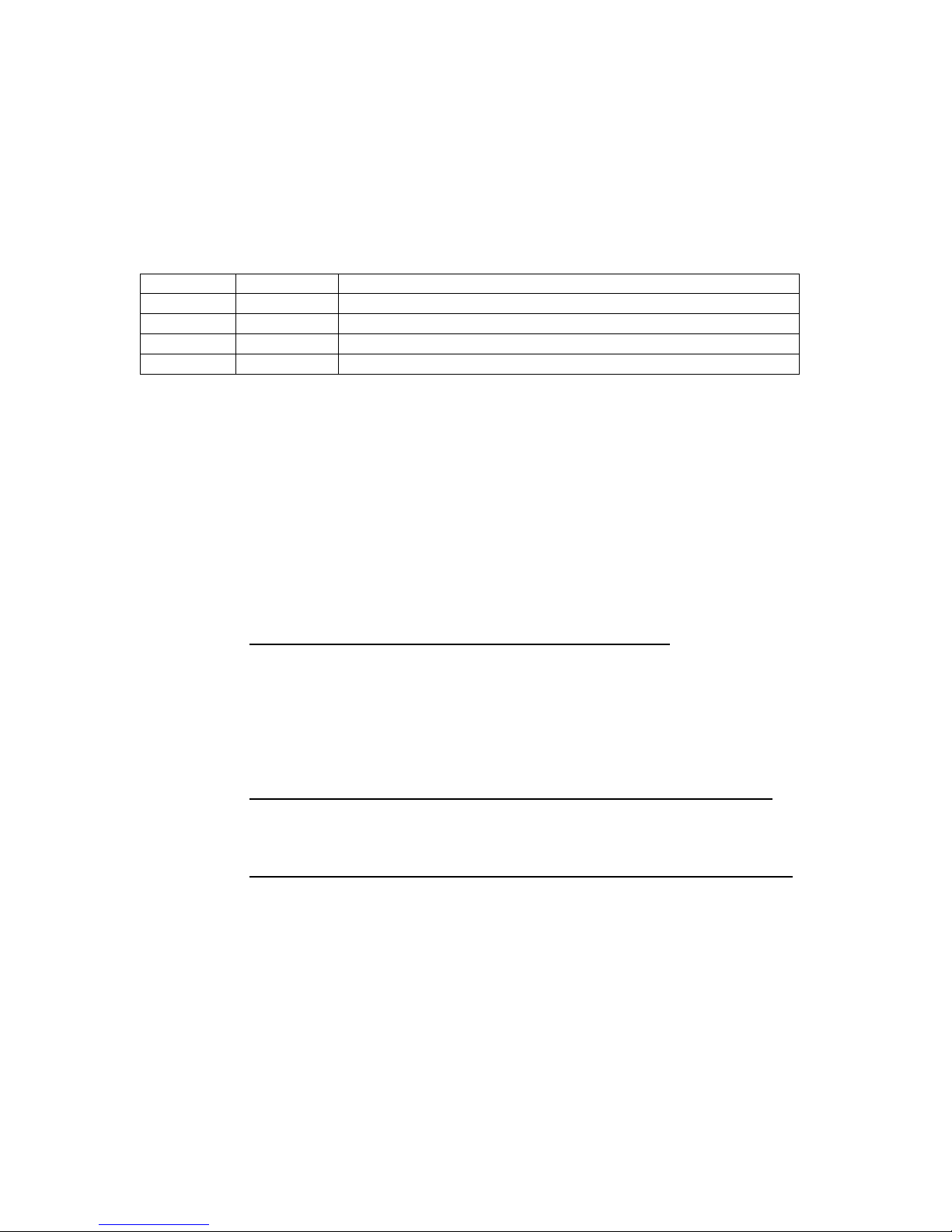
INTERNAL FUNCTION TABLE
Function Symbol Description
1 F.1 Span value reading and dealer calibration
2 F.2 Full display segment and max. capacity check
3 F.3 Check offset value and scale configuration
4 F.4 Auto power off setting
HOW TO ENTER THE REQUIRED FUNCTION MODE
a. Turn scale off.
b. Press and hold TARE, then turn scale on. Scale display F.1
c. Press TARE until the required function number appears.
d. Press MODE
e. Press MODE until the required setting appears.
f. Press TARE to confirm.
g. Repeat step c to f for other function setting, or
h. Press ON/ZERO to save settings and return to normal
operation.
F.1 Span Value Reading and Dealer Calibration
a. Simply enter F.1 to read the A/D counts.
b. Press ON/ZERO to clear t
he A/D counts, apply test mass
onto platter, the span value of test mass will be
displayed.
c. Refer to Dealer Calibration procedures for dealer
calibration.
F.2 Display Segment and Rated Capacity & Division Check
When funtion is entered, all segment will be displayed.
Check and make sure that no segments are missed.
F.3 Total Internal Count Checking and Scale Configuration
1 Enter F.3, scale displays the Offset Value when unloaded.
2 Apply extra load onto platter, the total internal count
value will be displayed.
SELECT WEIGHT UNITS
1 Press and hold MODE until the weight unit appears.
2 To employ all(metric and pound) weight units, press
MODE until lb appears. To disable pound weight unit,
press MODE until kg appears.
3 Press ON/ZERO to save setting and back to normal operation
status.
Page 8

8
F.4 Auto Power Off Setting
Two modes are available: (Default=4_OFF)
0._OFF = Auto Power Off function is disabled.
4._OFF = Scale will automatically be turned off after
4 minutes unused.
3.2 AUTO AND DEALER CALIBRATION PROCEDURES
ACCEPTABLE LOAD FOR AUTO AND DEALER CALIBRATION
Model
Number
External
Division
Acceptable Auto and Dealer
Calibration Load
AM-3000 1/3000 1kg 2kg
AM-6000 1/3000 2kg 4kg
AM-15K 1/3000 5kg 10kg
AM-30K 1/3000 10kg 20kg
Dealer Calibration Procedures:
1 Turn scale off.
2 Press and hold TARE, then turn scale on.
3 Scale displays F.1
4 Press MODE
5 Scale displays offset value
6 Press ON/ZERO
7 Press TARE
8 Press ON/ZERO
9 Press TARE
10
Press ON/ZERO, scale displays a circle at the right hand
of the
display. It means the scale is ready for dealer
calibration.
11 Make sure that the figure being displayed is =0 or 1,
If not, press ZERO again.
12 Load calibration either load as listed on above table.
13 When value displayed is stable, press MODE.
14 Wait until the scale starts count down.
15 Calibration completed and scale is ready for operation.
Page 9

9
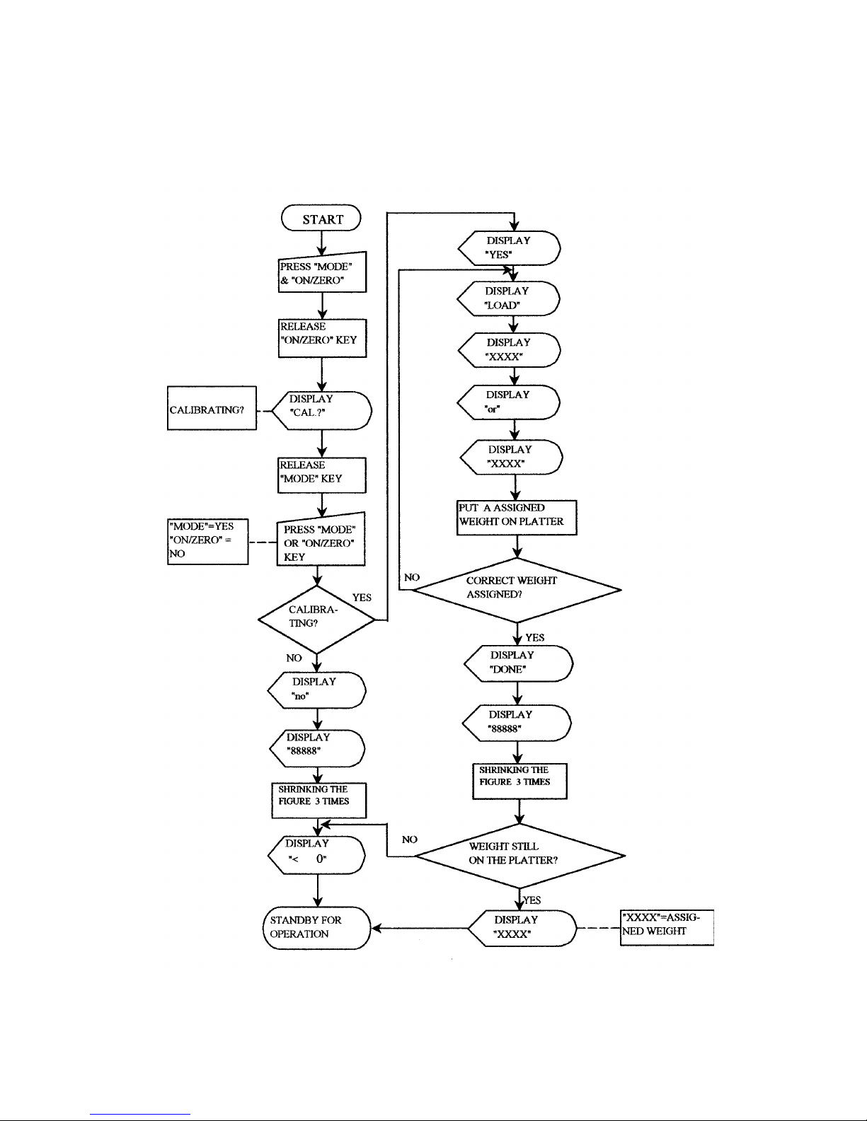
Auto Calibration Procedures:
1 Turn scale off
2 Press and hold MODE, then turn scale on.
3 Scale displays CAL?
4 Press MODE
5 Scale displays LOAD XXXX or XXXX
6 Load calibration load according to above table.
7 Wait until the scale display DONE and starts count down.
8 Calibration completed and scale is ready for operation.
3.3 DISABLE CALIBRATION WITH DIP SW.(S1)
The DIP SW.#1 is used to control calibration. Push this switch
to ON position to disable calibration.
3.4 OFFSET AND SPAN VALUE DATA
OFFSET AND SPAN VALUE DATA TABLE
Model
Number
Offset
Value
(Thousand)
Span Value(Thousand) at
Various Load Applied
Offset
Control
Span Control(Ohm)
R1A
AM-3000 10~14
10~15 at
1kg
20~30 at
2kg
VR1 Trimmer 35K
AM-6000 10~14 10~15 at
2kg
20~30 at
4kg
VR1 Trimmer 23.2K
AM-15K 10~14 10-15 at
5kg
20-30 at 10kg VR1 Trimmer 25K
AM-30K 10-14 10~15 at
10kg
20~30 at 20kg VR1 Trimmer 15K
READING OFFSET VALUE
1 Turn scale off
2 Remove all load from platter
3 Enter F.3 and read the offset value
READING SPAN VALUE
1 Turn scale off
2 Remove all load from platter
3 Enter F.1
4 Press ZERO
5 Apply load to platter. Span value according to load
applied will be displayed.
HOW TO ADJUST OFFSET VALUE
In case the offset value is out of range, adjust the trimmer
located at VR1 on the mainboard to obtain correct offset value.
Page 10

10
HOW TO ADJUST SPAN VALUE
The span value is controlled by resistor located on R1A, standard
resistor value of R1A is listed on the above table. If the
required span value is not attained, then change R1A resistor
according to either case below:
Span value too low : Increase the resistance of R1A.
Span value too high : Decrease the resistance of R1A.
Page 11
11
3.5 FLOW CHART
3.5.1 Auto Calibration(for end-user)
Page 12
12
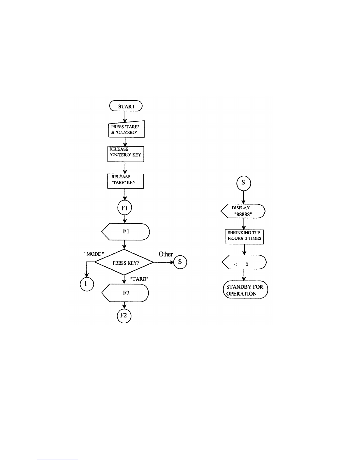
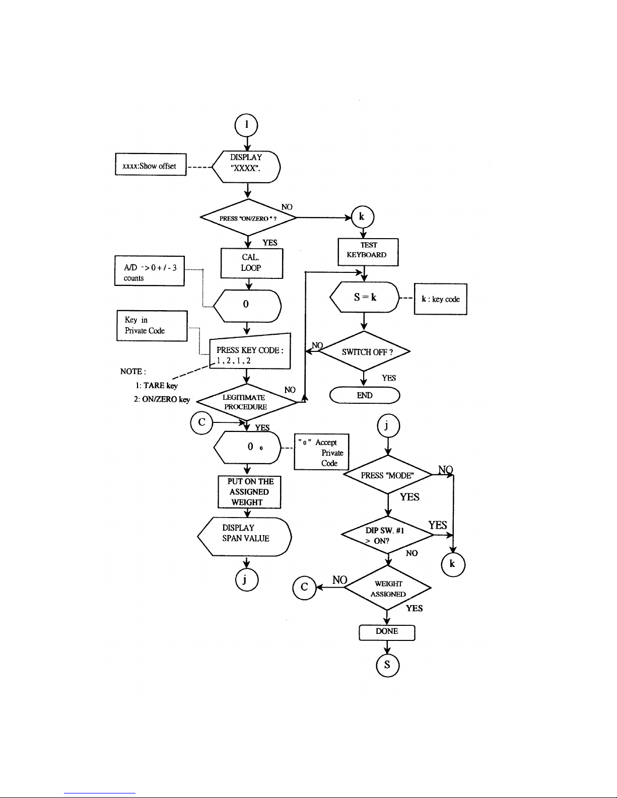
3.5.2 Function Test(for technicians only)
Page 13
13
Page 14

14
Page 15

15
4. TROUBLE SHOOTING
4.1 TROUBLE SHOOTING LOOP
Page 16

16
4.2 PARTS AND COMPONENTS TROUBLE SHOOTING
4.2.1 Power Supply Checking
4.2.1.1 Relevant parts:
Main Board(OM-10-X)
U11(C1061)
ZD1(8.2V)
BR1(W04/1A)
Q1(A1515)
Q2(C945)
Q4(C945)
R36(1.2 ohm,1/2W)
U9(HT-7039)
U8(AIC 1722-3.3)
ZD2(5.1V)
Description:
1) AC Adaptor: This AC Adaptor provides power for
DC9~12V,500mA(for CE Version)
2) Battery: Built-in Rechargeable Battery 6V/4Ah
3) How Battery is charged completely?
The charging voltage is regulated by Q1(C1061) and
ZD1(8.2V) for about 7 volts.
The charging current will go down automatically when
voltage reached.
Q4(C945) and R36(1.2R,1/2W) provide Over-Current
protection.
Page 17

17
4) +3.3V power drives analog and digital circuit system.
U8(AIC 1722-3.3) is a 3.3volts Voltage Regulator.
5) Auto-off:
If the scale is set on 4_oFF or even under LO-BAT
situation, after some minutes the CPU will release
a low potential signal to draw-
down Q2, then Q1
cuts off, the scale will be shut down immediately.
6) Low Power Detection:
The U9(HT-
7039) is designed to detect the power
level.
When battery power is less than 5.5V, it will
release a low potential signal to CPU, and then CPU
will instruct LCD display to show LO-BAT symbol.
4.2.1.2 Input voltage: 5.5V or higher
Check and recharge battery if voltage less than 5.5V.
Check DC-JACK or AC Adaptor if been defective
(CE Version).
4.2.1.3 System voltage(Vcc): 3.3V +/- 10%
Check that the system voltage is within 3.3V +/- 10%
a) less than 3V, the CPU may not work properly.
b) more than 6V, ghost will appear on LCD.
4.2.2 Platter Stopper Checking
The platter device shall not touch anything around itself
during operation. Check that the platter is not contacted
with the upper(no load) and/or lower (with load) stopper.
4.2.3 LCD Display Checking
4.2.3.1 Check that it is soldered and connected properly
between LCD and driver IC(uPD7225), driver
IC(uPD7225)and CPU.
4.2.3.2 Check whether LCD is broken.
Page 18

18
4.2.4 CPU Checking
4.2.4.1 Check that all pins are seated properly into the
socket.
4.2.4.2 Check that the Crystal Oscillator works.
4.2.4.3 Check the RESET is normally low.
4.2.5 A/D Unit Checking
4.2.5.1
Check that the +3.3V & +5V powers are correctly fed
to the A/D unit.
4.2.5.2 Check that the signal output of loadcell is normal.
4.2.5.3 Check OP. Amplifiers & A/D Converter(AD7715).
When no error is found with the above checking procedures, the
trouble can be caused on the loadcell or the PCB itself. Replace
a new one could be better to identify the defective.
In this way, the readout of weight would be varied because of
The output voltage of loadcell and different span value, so
recalibration is required after this replacement.
Page 19

19
5. ELECTRICAL CIRCUITRY
5.1 SCHEMATICS
Page 20

20
Page 21

21
Page 22

22
Page 23

23
Page 24

24
5.2 PCB LAYOUT
Page 25

25
Page 26

26
Page 27

27
6. BILL OF MATERIAL
STRUCTURE
Parts No. Description Specification Qty Remark
E1OM0000010 P.C.B. KIT OM-10-X MAINBOARD 1
E1OM0001000 P.C.B. KIT OM-41-X REAR BOARD 1 OPTION
E1FM1000000 P.C.B. KIT FM-50-X A/D BOARD 1
A0002****** LOAD CELL C2G1-F CAPACITY = 6KG 1 AM-3000
C2G1-F CAPACITY = 10KG 1 AM-6000
C2G1-F CAPACITY = 20KG 1 AM -15K
C2G1-F CAPACITY = 35KG 1 AM-30K
G0001OM0120 UPPER CABINET OM SERIES (WHITE) 1 EMI COATING
G0001OEP020 UNDER CABINET OEP SERIES (GRAY) 1 EMI COATING
F0003OEC100 ALUMINUM L/C SUPPORT(UPPER) OEC,EC SERIES 1
F0003OEC101 ALUMINUM L/C SUPPORT(UNDER) OEC,EC SERIES 1
G0002OEP000 PLASTIC PLATTER OEP SERIES 1
F0009000033 STAINLESS STEEL PLATE NO.33 OEP SERIES 1 FOR PLATTER
A5005000090 BUBBLE LEVEL D14 1
G0005OEC000 PLATTER BEARING RUBBER OEC SERIES 4
G0004OEC001 ADJUSTABLE FEET E SERIES 4
A1600060400 RECHARGEABLE BATTERY GP4-6/6V 4Ah 1
C1BW1000000 PANEL PC BW SERIES 119x40.5x1 mm 1
C1AM0010000 OVERLAY AM SERIES 1
C1OEC030997 REAR PANEL OEC SERIES (GRAY)+SERIES NO. WINDOW 1
C1AM******* REAR PANEL AM SERIES REAR DISPLAY 1 OPTION
G0009EM0002 BATTERY CAP EM SERIES (GRAY) 1
A1208020801 BATTERY WIRE ARRAY 2 PIN 80cm(SINGLE HOUSING) 1
Z7OLP000000 DUST COVER OLP SERIES 1
F0013SPC000 BATTERY CLAMP SP-III SERIES 1
A0906000220 D.C. JACK SCD-022(BLACK) 1
E0000000000 D.C. JACK FIXING PLATE OEP SERIES 2
Y0007OEP000 PACKAGING OEC SERIES 1
A1007000004 FERRITE CORE T-28.3*13.8*13.5 1 DC JACK
A1007000005 FERRITE CORE U23.8*11.4*14 1 LOAD CELL
A1007000001 FERRITE CORE TR-16*9*28 1 BATTERY
A6010221250 ADAPTOR 230V/9V 500mA 1
OM-10-X MAINBOARD
E0OM1000010 P.C.B. OM-10-X 1
A0208072250 I.C. UPD7225G 1 U6
A0202093462 I.C. 93LC46 1 U5
A0207017223 VOLTAGE REGULATOR I.C. AIC-1722-33CZT 1 U8
A0250070390 I.C. HT7039 1 U9
A0300000040 I.C. SOCKET 40 PIN 1 U4
A0401009450 TRANSISTOR 2SC945 2 Q2,Q4
A0401015150 TRANSISTOR A1515 1 Q1
A0401007330 TRANSISTOR A733 1 Q5
A0401010610 TRANSISTOR C1061C OR D880 1 U11
A0501004148 DIODE 1N4148 2 D1,D3
A0501004002 DIODE 1N4002 1 D7
A0503020082 ZENER DIODE 1/2W 8V2(9A3) 1 ZD1
A0503020056 ZENER DIODE 1/2W 5V6(6B1) 1 ZD2
A0701108016 CAPACITOR (EC) 1000uF/16V 1 C36
Page 28

28
A0701227017 CAPACITOR (EC) 220uF/16V (SS TYPE) 1 C28
A0701106017 CAPACITOR (EC) 10uF/16V (SS TYPE) 11 C14,C18,
C21~24,C26,
C29,C31,C39,
C40
A0730104050 CAPACITOR (MLC) 104Z 6 C17,19,27,
30,32,38
A0740020050 CERAMIC CAPACITOR (CC) 20pF 2 C15~16
A0804042322 METAL FILM RESISTOR 23.2K OHM 1/4W 1 R32
A0805041103 CARBON FILM RESISTOR 10K OHM 1/4W 8 R13,R18~20,
R26,R29,
R30~31
A0805041104 CARBON FILM RESISTOR 100K OHM 1/4W 2 R33,R43
A0805041102 CARBON FILM RESISTOR 1K OHM 1/4W 2 R14,R44
A0805041331 CARBON FILM RESISTOR 330K OHM 1/4W 1 R17
A0805041472 CARBON FILE RESISTOR 4.7K OHM 1/4W 3 R16,21,27
A0805041223 CARBON FILE RESISTOR 22K OHM 1/4W 1 R28
A0805041153 CARBON FILE RESISTOR 15K OHM 1/4W 1 R37
A0805041221 CARBON FILE RESISTOR 220 OHM 1/4W 1 R38
A0805041471 CARBON FILE RESISTOR 470 OHM 1/4W 1 R39
A0805020120 CARBON FILE RESISTOR 1.2 OHM 1/2W 1 R36
A0805021101 CARBON FILE RESISTOR 100 OHM 1/2W 1 R35
A0802047309 RESISTOR NETWORK 47K OHM 9 PIN 1 NR1
A0910100130 SOCKET STRIPS SIP 1 X 13 (FEMALE) 2 FOR LCD
A1301000002 DIP S/W DS-02 (4 PIN) 1 S1 A1100260000
CRYSTAL 6.0 MHz 1 X1
A1500000004 BUZZER OBO-15210 1 BZ1
A1306000004 TACT SW KA-130 4 SW1~4
A0901010040 CONNECTOR 4 PIN WAFER 1 J4 (RS-
232
OPTION)
A0902010020 CONNECTOR 2 PIN WAFER,PITCH=3.9mm 2 J2,10
A0625050000 L.E.D. ROUND,5mm,(RED,GREEN) 1
A5004000003 HEAT SINK MB-207-20 1 U11
A0201089511 I.C. 89C51 1 U4
A0102000289 L.C.D. G289 1
FM-50-X A/D BOARD
E0FM0010000 P.C.B. FM-50-X 1
F0015000004 PROTECTION BOX EM SERIES(UPPER) 1
F0015000005 PROTECTION BOX EM SERIES(LOWER) 1
A0203077150 I.C. AD7715-3 1 U3
A0206000071 I.C. OP-07CP 2 U1,2
A0207017223 VOLTAGE REGULATING I.C. AIC1722-33CZL 1 U4
A0702106016 CAPACITOR (TC) 10uF/16V 1 C8
A0730104050 CAPACITOR (MLC) 0.1uF/50V(104) 8 C2,6,7,9~12,
16
A0710224101 POLYESTER FILM CAPACITOR(MEF) 0.22uF/100V(224) 1 C5
A0713474063 POLYESTER FILM CAPACITOR(MEF) 0.47uF(474) 2 C3,4
A0720103101 POLYESTER FILM CAPACITOR(PET) 0.01uF/100V(103J) 1 C1
A0750122050 FEED THROUGH CAPACITOR(CCFT) 1200pF/50V 4 C13~16
A0803041002 METAL FILM RESISTOR(10PPM) 10K ohm,1/4W 2 R7,9
A0803042002 METAL FILM RESISTOR(10PPM) 20K ohm,1/4W 1 R8
A0804048002 METAL FILM RESISTOR 80K ohm,1/4W 1 R1A
A0804041003 METAL FILM RESISTOR 100K ohm,1/4W 4 R2~5
Page 29

29
A0804046801 METAL FILM RESISTOR 6.8K ohm,1/4W 1 R12
A0804042002 METAL FILM RESISTOR 20K ohm,1/4W 1 R6
A0801001203 TRIMMER 3006P-001-203(20K) 1 VR1
A0901010060 CONNECTOR 6 PIN WAFER 1 J2
A1005030512 FERRITE BEAD 3.5 x 6 x 0.8 mm 10 L1~10
A1202060251 WIRE ARRAY 6 PIN 25cm 1
OM-10-X MAINBOARD (EL OPTION)
EL OPTION:
A1401005120 BACK LIGHT INVERTER 5V TO 120V 1 IN1
A1400000006 BACK LIGHT EL-13044 (134 X 44 mm) 1 EL1
A0401033770 TRANSISTOR C2001 OR C3377 1 Q3
A0401007330 TRANSISTOR A733 1 Q7
A0730104050 CAPACITOR (MLC) 104Z 1 C25
A0701106017 CAPACITOR (EC) 10uF/16V (SS TYPE) 1 C33
A0805041103 CARBON FILM RESISTOR 10K OHM 1/4W 1 R23
A0805041102 CARBON FILM RESISTOR 1K OHM 1/4W 1 R22
A0805041180 CARBON FILM RESISTOR 18 OHM 1/4W 1 R24
OM-41-X REAR BOARD (OPTION)
E0OM******* P.C.B. OM -41-X 1
A0102000289 L.C.D. G289 1
A0910100130 SOCKET STRIPS SIP 1 X 13 (FEMALE) 2 FOR LCD
A0907020300 CONNECTOR(PIN PLUG) 2 X 15 PIN 2
A1203300340 FLAT CABLE 30 PIN 34cm 1
OM-41-X REAR BOARD (EL OPTION)
A1401005120 BACK LIGHT INVERTER 5V TO 120V 1 IN1
A1400000006 BACK LIGHT EL-13044 (134 X 44 mm) 1 EL1
A0730104050 CAPACITOR (MLC) 104Z 1 C1
A0701106017 CAPACITOR (EC) 10uF/16V (SS TYPE) 1 C6
A0805041180 CARBON FILM RESISTOR 18 OHM 1/4W 1 R9
==============================================================================
Page 30

30
7. APPENDIX
PARTS EXPLOSION:
Page 31

31
ITEM PART NAME DESCRIPTION QTY
1 STAINLESS STEEL PLATE NO.33 OEC SERIES 1
2 PLASTIC PLATTER OEP SERIES 1
3 PLASTIC UPPER CABINET OM SERIES(EMI COATING) 1
4 OVERLAY PC AM SERIES 1
5 REAR PANEL PC OEC SERIES 1
6 BUBBLE LEVEL D14 1
7 P.C.B. OM-10-X 1
8 DC JACK FIXING PLATE OEP SERIES 1
9 DC JACK SCD-022(BLACK) 1
10 PLASTIC UNDER CABINET OEP SERIES(GRAY) 1
11 BATTERY CLAMP SP-III SERIES 1
12 RECHARGEABLE BATTERY 6V 4Ah 1
13 P.C.B. FM-50-X 1
14 PROTECTION BOX EM SERIES(UPPER) 1
15 PROTECTION BOX EM SERIES(UNDER) 1
16 ADJUSTABLE FEET E SERIES 4
17 BATTERY CAP EM SERIES(GRAY) 1
18 PLATTER BEARING RUBBER OEC SERIES 4
19 ALUMINUM L/C SUPPORT(UPPER) OEC,EC SERIES 1
20 LOAD CELL C2G1-F 1
21 ALUMINUM L/C SUPPORT(UNDER) OEC,EC SERIES 1
22 PANEL PC BW SERIES(119 x 40.5 x 1mm) 1
23 SCREW M4 x 25 , ROUND HEAD 3
24 SCREW M6 x 20 2
25 SPRING WASHER M7 2
26 SCREW M4 x 20 , FLAT HEAD(NYLOK) 2
27 SCREW M4 x 10 , ROUND HEAD 4
28 SCREW M4 x 20 , ROUND HEAD 1
29 NUT M4 1
30 SPRING WASHER M7 2
31 SCREW M6 x 20 2
Page 32

32
Page 33

33
Page 34

34
Page 35

35
Page 36

36
Page 37

37
Page 38

38
Page 39

39
Page 40

40
C2G1-F LOAD CELL SPECIFICATION SHEET
RATED CAPACITY 3,6,10,15,20,35kgf
SAFE OVERLOAD 150%R.C.
ULTIMATE OVERLOAD 200%R.C.
RATED OUTPUT
2mV/V ¡0.2mV/V
NON-LINEARITY 0.015%R.O.
HYSTERESIS 0.015%R.O.
REPEATABILITY 0.02%R.O.
CREEP 0.02%R.O./20min.
CREEP RECOVERY 0.02%R.O./20min.
EXCITATION, RECOMMENDED 12V
EXCITATION, MAXIMUM 20V
ZERO BALANCE
¡5%R.O.
TERMINAL RESISTANCE, INPUT
400£(+20£ -20£)
TERMINAL RESISTANCE, OUTPUT
350¡5£
INSULATION RESISTANCE
2000M£ or more (DC 50V)
TEMP. RANGE COMPENSATED
-10~50¢
TEMP. RANGE SAFE
-10~50¢
TEMP EFFECT ON ZERO BALANCE
0.023%R.O./10¢
TEMP. EFFECT ON OUTPUT
0.010%LOAD/10¢
CABLE AND LENGTH
£
3.2, 4 cores shield cable
(40cm)
WEIGHT APPROX. 200g
OUTLINES
Page 41

41
 Loading...