

Page 1

Part I
The Modular
LYNX System
!
!
!
!
!
!
!
!
!
Modular LYNX
!
!
Getting Started
Connecting the LYNX System
Mounting the LYNX System
Powering the LYNX System
The Communications Interface
Configuring the Digital I/O
The LYNX Control Module
The LYNX Control Module (Combination)
The Isolated Digital I/O Module
The Differential Digital I/O Module
The Combination Digital I/O Module
Page 2

Table of Contents
Section 1: Getting Started ...................................................................................................................................................1-5
Section Overview ............................................................................................................................................................................1-5
Getting Started.................................................................................................................................................................................1-5
Included in the Package.................................................................................................................................................... 1-5
User Provided Tools and Equipment Needed...................................................................................................................1-6
Connecting the Power Supply..........................................................................................................................................1-6
Connecting the Step Motor Driver ..................................................................................................................................1-6
Motor Connections ..........................................................................................................................................................1- 6
Communications Wiring ..................................................................................................................................................1-6
Establishing Communications using the IMS LYNX Terminal........................................................................................1-6
Testing the LYNX Setup ..................................................................................................................................................1-7
Section 2: Connecting the LYNX System ............................................................................................................................1-9
Section Overview ............................................................................................................................................................................1- 9
Connecting the System ...................................................................................................................................................................1-9
Section 3: Mounting the L YNX System .............................................................................................................................1-10
Section Overview ......................................................................................................................................................................... 1-10
Panel Mount ................................................................................................................................................................................. 1-10
Din Rail Mounting Option ........................................................................................................................................................... 1-10
Included in the DIN Rail Mounting Kit ........................................................................................................................ 1-10
Mounting the LYNX System to a DIN Rail .................................................................................................................. 1-10
Section 4: Powering the L YNX System .............................................................................................................................. 1-12
Section Overview ......................................................................................................................................................................... 1-12
Wiring and Shielding .................................................................................................................................................................... 1-12
Rules of Wiring ............................................................................................................................................................. 1-12
Rules of Shielding .......................................................................................................................................................... 1-12
LYNX Control Module with IMS Driver ..................................................................................................................................... 1-13
Stand-alone or with Optional I/O Modules .................................................................................................................................. 1-14
+12 to +75VDC Supply ................................................................................................................................................ 1-14
+5 VDC Supply .............................................................................................................................................................. 1-14
Power Requirements ...................................................................................................................................................... 1-15
Section 5: The Communications Interface .......................................................................................................................1-16
Section Overview ......................................................................................................................................................................... 1-16
Connecting the RS-232 Interface ................................................................................................................................................ 1-16
Single Control Module System ...................................................................................................................................... 1-16
Multiple Control Module System .................................................................................................................................. 1-17
Connecting the RS-485 Interface ................................................................................................................................................ 1-20
Single Controller System ............................................................................................................................................... 1-20
Multiple Controller System........................................................................................................................................... 1-21
LYNX Control Module Modes of Operation ............................................................................................................................... 1-23
Immediate Mode ........................................................................................................................................................... 1-23
Program Mode .............................................................................................................................................................. 1-23
EXEC Mode .................................................................................................................................................................. 1-23
LYNX Control Module Communication Modes .......................................................................................................................... 1-23
ASCII ............................................................................................................................................................................. 1-23
Binary............................................................................................................................................................................ 1-24
Section 6: Configuring the Digital I/O .............................................................................................................................. 1-25
Section Overview ......................................................................................................................................................................... 1-25
System I/O Availability by Module .............................................................................................................................................. 1-25
The Isolated Digital I/O ............................................................................................................................................................... 1-26
Uses of the Isolated Digital I/O..................................................................................................................................... 1-26
The IOS V ariable ........................................................................................................................................................... 1-27
Configuring an Input ..................................................................................................................................................... 1-28
Configuring the Digital Filtering ................................................................................................................................... 1-28
Configuring an Output................................................................................................................................................... 1-29
The IO Variable ............................................................................................................................................................. 1-29
Read/Write an I/O Group .............................................................................................................................................. 1-30
The Differential I/O ..................................................................................................................................................................... 1-31
The Clock Interface ...................................................................................................................................................... 1-31
Clock Types Defined..................................................................................................................................................... 1-31
Configuring The Differential I/O - The IOS Variable ................................................................................................... 1-32
Configuring an Input ..................................................................................................................................................... 1-32
Setting the Digital Input Filtering for the Differential I/O .......................................................................................... 1-33
Configuring an Output................................................................................................................................................... 1-33
1 - 2 Modular LYNX System 12.05.2003
Page 3

Typical Functions of the Differential I/O.................................................................................................................................... 1-34
Connecting and Using an Encoder ................................................................................................................................ 1-34
Translating the EUNIT Variable to a Dimension of Distance ...................................................................................... 1-35
Half Axis Operation (Follower) .................................................................................................................................... 1-36
One and a Half Axis Operation (RATIOE)................................................................................................................... 1-37
Section 7: The LYNX Control Module (LX-CM100-000) .................................................................................................. 1-39
Section Overview ......................................................................................................................................................................... 1-39
Hardware Specifications ............................................................................................................................................................... 1-39
Environmental Specifications ....................................................................................................................................... 1-39
Mechanical Specification .............................................................................................................................................. 1-39
Connection Overview .................................................................................................................................................................. 1-40
Power Requirements ...................................................................................................................................................... 1-40
LED Indicators ............................................................................................................................................................................. 1-41
Pin Assignment and Description.................................................................................................................................................. 1-41
Switch Assignments ...................................................................................................................................................................... 1-42
Section 8: The LYNX Control Module (Combination) .................................................................................................... 1-43
Section Overview ......................................................................................................................................................................... 1-43
Hardware Specifications ............................................................................................................................................................... 1-43
Environmental Specifications ....................................................................................................................................... 1-43
Mechanical Specification .............................................................................................................................................. 1-43
Connection Overview .................................................................................................................................................................. 1-44
Power Requirements ...................................................................................................................................................... 1-44
LED Indicators ............................................................................................................................................................................. 1-45
Pin Assignment and Description.................................................................................................................................................. 1-45
Switch Assignments ...................................................................................................................................................................... 1-46
Section 9: The Isolated Digital I/O Module ......................................................................................................................1-47
Section Overview ......................................................................................................................................................................... 1-47
Hardware Specifications ............................................................................................................................................................... 1-47
Environmental Specification ........................................................................................................................................ 1-47
Mechanical Specification .............................................................................................................................................. 1-47
Connection Overview .................................................................................................................................................................. 1-48
Pin Assignments And Description ............................................................................................................................................... 1-48
Switch Assignments And Description .......................................................................................................................................... 1-49
Input Specifications ...................................................................................................................................................................... 1-49
Input Filtering .............................................................................................................................................................................. 1-50
Output Specifications ................................................................................................................................................................... 1-50
Section 10: The Differential Digital I/O Module.............................................................................................................. 1-51
Section Overview ......................................................................................................................................................................... 1-51
Hardware Specifications ............................................................................................................................................................... 1-51
Environmental Specification ........................................................................................................................................ 1-51
Mechanical Specification .............................................................................................................................................. 1-51
Connection Overview .................................................................................................................................................................. 1-52
Power Requirements ..................................................................................................................................................................... 1-52
Pin Assingments And Description ............................................................................................................................................... 1-53
Input Specifications ...................................................................................................................................................................... 1-53
Input Filtering .............................................................................................................................................................................. 1-54
Output Specifications ................................................................................................................................................................... 1-55
Modular L YNX System
Table 4.1: Power Requirements ............................................................................................................................................... 1-15
Table 5.1: Wiring Connections: RS-232 Interface Single Control Module System ................................................................. 1-17
Table 5.2: Party Mode Address Configuration Switch Settings ............................................................................................... 1-18
Table 5.3: Connections and Settings Multiple Control Module System, RS-232 Interface .................................................... 1-19
Table 5.4: RS-485 Interface Connections ............................................................................................................................... 1-20
Table 5.5: Party Mode Address Configuration Switch Settings ............................................................................................... 1-21
Table 5.6: RS-485 Interface Connections and Settings, Multiple Control Module System .................................................... 1-22
Table 5.7: ASCII Mode Special Command Characters............................................................................................................. 1-24
Table 5.8: Binary Hex Codes ................................................................................................................................................... 1-24
Table 6.1: System I/O Availability by Module ......................................................................................................................... 1-25
Table 6.2: IOS V ariable Settings ............................................................................................................................................... 1-27
Table 6.3: Digital Filter Settings for the Isolated I/O .............................................................................................................. 1-28
Table 6.4: Binary State of Outputs .......................................................................................................................................... 1-30
Table 6.5: The Four Clocks and Their Default Line Placement ............................................................................................. 1-31
Table 6.6: Digital Filter Settings for the Differential I/O ........................................................................................................ 1-33
Modular LYNX System 12.05.2003
List of Tables
1 - 3
Page 4

Table 7.1: Power Requirements for the LYNX Control Module ............................................................................................. 1-40
Table 7.2: LYNX Control Module LED Indicators ................................................................................................................. 1-41
Table 7.3: LYNX Control Module Connector P1 Pin Configuration...................................................................................... 1-41
Table 7.4: LYNX Control Module Connector P2 Pin Configuration...................................................................................... 1-41
Table 7.5: LYNX Control Module Connector P3 Pin Configuration...................................................................................... 1-42
Table 7.6: LYNX Control Module Configuration Switches ..................................................................................................... 1-42
Table 7.7: L YNX Control Module Group 20 I/O Pull-up Switches.......................................................................................... 1-42
Table 7.8: L YNX Control Module Group 30 I/O Pull-up Switches.......................................................................................... 1-42
Table 8.1: Power Requirements for the LYNX Control Module (Combination) .................................................................... 1-44
Table 8.2: LYNX Control Module LED Indicators ................................................................................................................. 1-45
Table 8.3: LYNX Combination Control Module Connector P1 Pin Configuration................................................................ 1-45
Table 8.4: LYNX Combination Control Module Connector P2 Pin Configuration................................................................ 1-45
Table 8.5: LYNX Combination Control Module Connector P3 Pin Configuration................................................................ 1-46
Table 8.6: LYNX Combination Control Module Configuration Switches ............................................................................... 1-46
Table 8.7: LYNX Combination Control Module Group 20 I/O Pull-up Switches .................................................................... 1-46
Table 9.1: Isolated Digital I/O Module P1 Connector Pin Configuration ............................................................................... 1-48
Table 9.2: Isolated I/O Module Group 40 I/O Pull-up Switches ............................................................................................... 1-49
Table 9.3: Isolated I/O Module Group 50 I/O Pull-up Switches ............................................................................................... 1-49
Table 9.4: Isolated I/O Module Input Specifications ............................................................................................................... 1-49
Table 9.5: Digital Filter Settings for the Isolated I/O .............................................................................................................. 1-50
Table 9.6: Digital Filter Settings for the Isolated I/O .............................................................................................................. 1-50
Table 10.1: High Speed Differential I/O Module Power Requirements...................................................................................... 1-52
Table 10.2: High Speed Differential I/O Module Pin Configuration ......................................................................................... 1-53
Table 10.3: High Speed Differential I/O Module Input Specifications ...................................................................................... 1-53
Table 10.4: Digital Filter Settings for the Differential I/O........................................................................................................ 1-54
Table 10.5: LYNX Differential I/O Output Specifications ........................................................................................................ 1-55
List of Figures
Figure 1.1: Basic Setup Configuration, RS-232 Interface ............................................................................................................1-5
Figure 2.1: Removing the End Plates ..........................................................................................................................................1-9
Figure 3.1: Installing the DIN Rail Bracket .............................................................................................................................. 1-10
Figure 3.2: Installing the LYNX System on a DIN Rail............................................................................................................ 1-11
Figure 3.3: Removing the LYNX System from the DIN Rail................................................................................................... 1-11
Figure 4.1: Power Configuration. LYNX Control Module and external IMS Driver................................................................ 1-13
Figure 4.2: Stand-alone Power Configuration: 12-75VDC Supply ........................................................................................... 1-14
Figure 4.3: Stand-alone Power Configuration: 5VDC............................................................................................................... 1-14
Figure 5.1: Connecting the RS-232 Interface, Single Control Module System ........................................................................ 1-17
Figure 5.2: RS-232 Interface, Multiple Control Module System .............................................................................................. 1-19
Figure 5.3: RS-485 Interface, Single Controller System ........................................................................................................... 1-20
Figure 5.4: RS-485 Interface, Multiple Control Module System .............................................................................................. 1-22
Figure 6.1: Isolated I/O Applications........................................................................................................................................ 1-26
Figure 6.2: Isolated I/O Input .................................................................................................................................................... 1-28
Figure 6.3: Isolated I/O Output ................................................................................................................................................. 1-29
Figure 6.4: Clock Functions ...................................................................................................................................................... 1-31
Figure 6.5: IOS Variable Settings for the High Speed Differential I/O...................................................................................... 1-32
Figure 6.6: Differential I/O Input Equivalent Circuit ............................................................................................................... 1-32
Figure 6.7: Differential I/O Output Equivalent Circuit ............................................................................................................. 1-33
Figure 6.8: Connecting and Using an Encoder .......................................................................................................................... 1-35
Figure 6.9: Half Axis Mode (Following) ................................................................................................................................... 1-37
Figure 6.10: One and a Half Axis Operation .............................................................................................................................. 1-38
Figure 7.1: L YNX Control Module Dimensions ....................................................................................................................... 1-39
Figure 7.2: L YNX Control Module, Switches and Connections................................................................................................ 1-40
Figure 8.1: L YNX Control Module (Combination) Dimensions............................................................................................... 1-43
Figure 8.2: LYNX Control Module (Combination) Connections and Switches........................................................................ 1-44
Figure 9.1: L YNX Isolated I/O Module Dimensions ................................................................................................................. 1-47
Figure 9.2: Isolated Digital I/O Module Connection Overview ................................................................................................ 1-48
Figure 9.3: LYNX Isolated I/O Input Equivalent Circuit .......................................................................................................... 1-49
Figure 9.4: L YNX Isolated I/O Output Equivalent Circuit........................................................................................................ 1-50
Figure 10.1: LYNX Differential I/O Module Dimensions ........................................................................................................... 1-51
Figure 10.2: High Speed Differential I/O Module Connection Overview ................................................................................... 1-52
Figure 10.3: LYNX Differential I/O Input Equivalent Circuit.................................................................................................... 1-54
Figure 10.4: LYNX Differential I/O Output Equivalent Circuit ................................................................................................. 1-55
1 - 4 Modular LYNX System 12.05.2003
Page 5

Section 1
Section Overview
The purpose of this section is to get you up and running quickly.
This section will help you do the following:
! Connect power to the L YNX Control Module.
! Connect and establish communications in single mode.
! Write a simple test program.
Getting Started
*See Driver Documentation
for Current Adjust Resistor Value
Current Adjust
Resistor*
GND
V+
Black/Orange-White
Orange/Black-White
Red/Yellow-White
Yellow/Red-White
P2
ISP200-4
V+
GND
AC Ground (Green)
AC Neutral (White)
AC Line (Black)
Stepping
Motor
AC Line Cord
12345678
IM2000F
IM483 Step Motor Driver
Getting Started
Opto Supply
Direction
Step Clock
12345678
ON
1234
RS-232 Communications Wiring
Ground (DB-9 = Pin 5)
TX (Transmit) (DB-9 = Pin 3)
RX (Receive) (DB-9 = Pin 2)
ON
P1
1234
Resolution Select Programmed
for 256 Resolution)
INTELLIGENT MOTION SYSTEMS, INC.
123456
DIR-
DIR+
SCK-
SCK+
GND
+5V
RX-
RX+
TX-
TX+
CGND
RX
TX
PGND
V+
FAULT
POWER
123456 123456
21
22
23
24
25
26
21
22
23
24
25
26
31
32
33
34
35
36
IG
31
32
33
34
35
36
TM
Modular L YNX System
ISP200 - 4
Figure 1.1: Basic Setup Configuration, RS-232 Interface
Included in the Package
(1) L YNX Control Module ........................................................ (IMS P/N LX-CM100 or 200-000)
(2) End Mounting Brackets ...................................................... (IMS P/N LX-EB100-000)
(1) IMS CD ............................................................................... (IMS P/N IMS-CD100-000)
(1) Screw Driver ...................................................................... (IMS P/N SD1)
Modular LYNX System 12.05.2003
Host PC
LYNX Control Module
120VAC IN
1 - 5
Page 6

User Provided Tools and Equipment Needed
! Serial Cable
! IM483 or equivalent step motor driver
! ISP200-4 or equivalent power supply
! M-22XX or equivalent stepping motor
! Wire Cutters/Strippers
! 22 gauge wire for logic level signals
! 18 gauge wire for power supply and motor wiring
! PC with a free serial port (COM 1 or 2)
Connecting the Power Supply
1 . Using the 18 gauge wire, connect the DC output of your power supply to V+ on your L YNX
Control Module, and to P2, pin 4 on the IM483 Step Motor Driver. (Or V+ pin on equivalent
driver.) Figure 1.1.
2. Connect the Power Supply Return (GND) to PGND on the LYNX Control Module, and to
P2, pin 3 on the IM483 Step Motor Driver. (Or GND on equivalent driver .) Figur e 1.1.
3. Connect the AC Line cord to your power supply in accordance with any user documentation
Connecting the Step Motor Driver
accompanying the supply. DO NOT PLUG IN AT THIS TIME!
1 . Using 22 gauge wire, connect direction DIR+ on the L YNX Control Module to P1, pin 3 on the
2 . Connect Step Clock SCK+ of the LYNX Control Module to P1, pin 2 of the IM483 Driver . (Or
3 . Connect the +5V output off the LYNX Control Module to the Opto Supply P1, pin 4 of the
4 . Set the Resolution Select DIP switch on the IM483 Driver to ÷256 resolution. Figure 1.1.
IM483 Driver. (Or direction pin of equivalent drive used.) Figur e 1.1.
Step Clock input of equivalent drive used.) Figure 1.1.
IM483 Driver. (Or Opto Supply of drive used if required.) Figur e 1.1.
Motor Connections
Connect the motor to the IM483 Step Motor Driver in accordance with Figure 1.1.
Communications Wiring
Connect the Host PC to the L YNX Control Module (RS-232 Communications) in accordance with Figur e 1.1.
This is needed to program the L YNX Control Module.
Establishing Communications using the IMS Terminal
Included in the L YNX shipping package is a CD with the IMS T erminal software. This is a programming/
communications interface created by IMS to simplify the use of the L YNX. There is a 32 bit version for
Windows 9x/NT4/2000 located on the CD. The IMS Terminal is also necessary to upgrade the software in
your L YNX Control Module. These updates will be posted to the IMS website at http://www .imshome.com/
as they are made available.
T o install the IMS T erminal to your hard drive, insert the CD into your CD-ROM Drive. The CD should
autostart to the IMS Main Index Page. If the CD does not autostart, click “Start > Run” and type
“x:\IMS.exe” in the “Open” box and then click OK. NOTE: “x” is your CD ROM drive letter.
1 ) The IMS Main Index Page will be displayed.
2 ) Click the MicroLYNX icon in the upper right corner . This opens the LYNX Family Index Page.
3 ) Select IMS T erminal (Win9x) or IMS T erminal (W inNT).
4 ) Click SETUP in the Setup dialog box and follow the on-screen instructions.
1 - 6 Modular LYNX System 12.05.2003
Page 7

Once the IMS T erminal is installed you may run the Setup.
1 ) Open the IMS T erm by clicking Start>Programs>IMS T erminal>IMS T erm.
2 ) Select or verify the Communications Port that you will be using with your LYNX.
a) Click in the T erminal W indow to activate it.
b) Right click in the T erminal Window .
c) Click “Preferences” in the dialog box.
d) Click the “Comm Settings” tab at the top of the dialog box.
e) Under “Device” near the bottom of the box verify “LYNX” is selected. The BAUD
rate is already set to the LYNX default. Do not change this setting until you
have established communications with the L YNX Controller .
f) The “Window Size” settings are strictly optional. You may set these to whatever size
is comfortable to you.
g) Click “OK”. The setting will be saved automatically.
3 ) Apply power to the L YNX Controller . The following sign-on message should appear in the
T erminal window:
Program Copyright © 1996-2002 by:
Intelligent Motion Systems, Inc.
Marlborough, CT 06447
VER = xxxxx SER = Axxxxx
NOTE: If the sign-on message does not appear, check the “Connected/Disconnected” tab at the
bottom of the Terminal Window. If “Disconnected” is displayed, double click it to “Connect”.
Modular L YNX System
Detailed instructions for the IMS T erminal software can be located in Part III Softwar e Refer ence of this
manual.
Testing the LYNX Setup
Two basic instructions for communicating with a control module are SET and PRINT. The SET instruction is assumed and can be left off when communicating in ASCII mode. (Y ou are in ASCII mode whenever
you are using a text based terminal.) It is used to set variables and flags that define control module operation. The L YNX Software automatically recognizes the SET instruction whenever the name of the variable or
flag is typed into the terminal. Here we will set the motor units variable (MUNIT) to 51200 by typing the
following at the prompt (>):
MUNIT = 51200
The PRINT instruction is used to report the values of variables and flags. Now, double-check the value of
MUNIT by typing the following at the prompt (>):
PRINT MUNIT
The return from your terminal should be 51200. Note that the case is not important for instructions,
variables, and flags. They may be typed in upper or lower case.
Use the SLEW instruction to move the motor at a constant velocity. Be sure that the velocity provided is a
reasonable value for your motor and drive and try to move the motor. For instance, at the prompt type:
SLEW 10
This will move the motor at a speed of 10 munits per second. If the motor does not move, verify that the
wiring is in accordance with Figure 1.1. If a non IMS driver is being used, you may need to consult the user
manual for that device.
Modular LYNX System 12.05.2003
1 - 7
Page 8

Once you have been able to move the motor, the next step is to write a simple program to illustrate one of the
dynamic features of the LYNX: the ability to convert motor steps to a dimension of linear or rotary distance.
Let’s begin by discussing the relationship between the MUNIT variable and user units. Typically when we
perform a move we want to know the distance of that move in a familiar unit of measurement. That means
translating motor steps to the desired unit of measurement. The LYNX Control Module has the capability of
doing this for you. You have already set the motor units variable (MUNIT) to a value 51,200. With the
driver set to a resolution of 256 micro-steps per step and a 1.8° step motor that will be equal to 1 revolution
of the motor, or one USER UNIT. A user unit can be any unit of measure. At this point, by entering the
instruction MOVR 1, the motor will turn one complete revolution relative to its current position. Therefore,
1 User Unit = 1 Motor Revolution. For the exercise below we will use degrees for our user unit. As the LYNX
Product Manual indicates, the calculation required to select degrees as our user unit in this case is:
51200 Micro-steps per rev ÷ 360 degrees = 142.222 Micro-steps per degree
By setting the MUNIT variable to 51200/360 the LYNX Control Module will perform the calculation to
convert the user unit to degrees. Now, when issued, a relative motion instruction “MOVR 90” the motor will
turn 90 degrees.
Now, enter a sample program that will convert motor steps to degrees, execute a 90° move, and report that
move every 100 milliseconds while the motor is moving. Type the following bold commands:
‘Enter Program Mode, start program at Location 2000.
PGM 2000
‘Label the program TSTPGM.
LBL TSTPGM
‘ Set the user units to degrees.
MUNIT = 51200/360
‘ Set the max. velocity to 25 degrees per second.
VM = 25
‘ Execute a relative move of 90 degrees.
MOVR 90
‘ Report the position every 100 ms while moving.
LBL PRINTPOS
DELAY 100
PRINT “Axis position is”, POS, “Degrees.”
BR PRINTPOS, MVG
‘End the program.
END
PGM
Now Type TSTPGM to run program.
This sample program will be stored starting at location 2000. It sets the conversion factor for the user units,
sets the maximum velocity and then starts a motion. While the motion is occurring, the position is reported
every 100 milliseconds.
At this point you may desire to restore the settings to their factory default as you may not wish to use
degrees as your user unit. To do this, you will use the CP, DVF, and IP instructions.
CP - Clear Program.
To clear the program, type CP 1, 1. This will completely clear program memory space. Should
you desire to only remove one program, the instruction “CP [Program Label]” i.e., “CP
TSTPGM” would clear only that program. In this exercise only one program was entered, “CP
TSTPGM” will clear it.
DVF - Delete User Defined Variables and Flags.
By entering DVF, all of the user defined variables will be removed. Although no Flags were set
in this exercise, this command would clear them were they used.
IP - Initialize Parameters
This instruction will restore all of the parameters to their factory default state.
After entering these instructions a SAVE instruction should be entered.
1 - 8 Modular LYNX System 12.05.2003
Page 9

Section 2
Connecting the LYNX System
Section Overview
Each module of the LYNX System is a closed unit with a header of pins and locking tabs to connect it to
another module in the system. Optional I/O modules are connected on the RIGHT side of the Control
Module. This section covers:
! Removing the End Plates.
! Connecting/Disconnecting System Modules.
Connecting the System
1 . Remove the end plate(s) [A] from the Control Module. Depressing the locking clips [C] with a
small screwdriver through the slot [B] on the top and bottom of the module and pulling them
apart does this. See figure 2.1
2. Align the locking clips of the module being connected with the slots on the module being
connected to.
3 . Press modules firmly together, there will be an audible “snap” when the locking clips are fully
engaged.
4 . Reinstall the end plates at the ends of the LYNX System. They are designed to fit either end.
5 . Y ou are now ready to mount your LYNX System to a panel or DIN Rail using the optional
hardware kit.
Modular L YNX System
A
B
C
STEP 2 STEP 3STEP 1
Figure 2.1: Removing the End Plates
WARNING! Exercise caution when removing end plates
or separating LYNX System modules! Internal
!
component damage may occur if the screwdriver is
inserted too far into the slots!
Modular LYNX System 12.05.2003
1 - 9
Page 10

Section 3
Mounting the LYNX System
Section Overview
This section covers the two basic methods of mounting the LYNX System.
! Panel Mount.
! DIN Rail Mounting Option.
Panel Mount
Using the panel mount option, the LYNX is designed to use #10 hardware (not included). Details such as
screw length and threads are dependent on your overall system design.
Din Rail Mounting Option
A DIN Rail mounting kit (IMS P/N LX-DB100-000) may be purchased as an option to your L YNX System. It
includes all the hardware necessary to mount the system to either of the following recommended DIN rails:
TS35 X 7.5 or TS35 X 15
Included in the DIN Rail Mounting Kit
Included in the DIN Rail Mounting Kit is the following hardware:
! 2 - IMS0065 DIN Rail Brackets
! 4 - #6 Split Lock W asher
! 4 - #6-32X7/16 L Pan Hd Machine Screws
! 4 - #6 Flat W asher .040 Thick
! 2 - #6 X .250 L Set Screw
! 1 - Instruction Sheet
Mounting the LYNX System
to a DIN Rail
In order to install your L YNX System on a
DIN rail complete the following:
1 . Insert the two DIN rail brackets
into the slots located in the
back of the system between the
end plates and L YNX modules.
The pull-tab on the DIN rail
bracket must be on the bottom.
2 . Using the #6 hardware pro-
vided, secure the bracket to the
end plates. Figure 3.1.
Tighten to 5 - 7 lb/in.
A
B
C
D
DIN Rail Bracket
A
DBBC
B
#6 Flat Washer
#6 Split Lock Washer
C
# 6-32 X 7/16 Machine
D
Screw (5 - 7 lb/in torque)
Figure 3.1: Installing the DIN Rail Bracket
1 - 10 Modular LYNX System 12.05.2003
Page 11

DIN Rail Bracket
A
DIN Rail
B
LYNX System
C
A
C
B
Figure 3.2: Installing the LYNX System on a DIN Rail
Modular L YNX System
3 . Holding the L YNX System at an angle
away from you, lower the upper slot of
the DIN rail attachment onto the top
edge of the DIN rail. Snap L YNX system
into place. Figure 3.2.
4 . Insert #6 X .250 L set screw (provided)
into the TOP threaded insert located
between the #6 screws on each end
plate. Figure 3.3. Tighten until 12-14 in/
oz. This will keep the system from sliding
on the DIN rail.
T o Remove the L YNX System from the DIN Rail:
1. Loosen the set
screws located in
the TOP threaded
insert between the
#6 screws on each
end plate.
2 . Grasp the pull-tabs
located on the
bottom of the DIN
Rail brackets to
B
release the L YNX
system from the
DIN Rail
(Figure 3.3 - C&D)
while gently lifting
the front of the
C
L YNX system.
3. Lift the L YNX
System A way from
the DIN Rail.
Figure 3.3: Removing the LYNX System from the DIN Rail
A
D
E
DIN Rail Bracket
A
DIN Rail
B
Pull Tab
C
# 6 X .250 Set Screw (Top Location Only)
D
E
12-14 in/oz torque.
Removal from DIN Rail
N
Modular LYNX System 12.05.2003
NOTE: The DIN Rail Mounting option should only be used on
ST A TIONARY Systems. It is not designed for transport!
1 - 11
Page 12

Section 4
Powering the LYNX System
Section Overview
This section covers the two basic power configurations for your LYNX System.
! Basic rules of wiring and shielding.
! L YNX Control Module with IMS Drivers.
! L YNX Control Module as Stand-alone or with Optional I/O Module.
Wiring and Shielding
Noise is always present in a system that involves high power and small signal circuitry . Regardless of the
power configuration that you use in your system, there are some wiring and shielding rules that you should
follow to keep your noise-to-signal ratio as small as possible.
Rules of Wiring
! Power Supply and Motor wiring should be shielded twisted pairs run separately from signal
carrying wires.
! A minimum of 1 twist per inch is recommended.
! Motors wiring should be shielded twisted pairs using 20-gauge wire, or 18 gauge or better for
distance greater than 5 feet.
! Power ground return should be as short as possible to established ground.
! Power Supply wiring should be shielded twisted pairs. Use 18 Gauge wire if load is less than 4
amps, or 16 gauge for more than 4 amps.
! Do not “Daisy-Chain” power wiring to system components.
Rules of Shielding
! The shield must be tied to zero-signal reference potential. In order for shielding to be effective
it is necessary for the signal to be earthed or grounded.
! Do not assume that earth ground is true earth ground. Depending on the distance to the main
power cabinet it may be necessary to sink a ground rod at a critical location.
! The shield must be connected so that shield currents drain to signal-earth connections.
! The number of separate shields required in a system is equal to the number of independent
signals being processed plus one for each power entrance.
! The shield should be tied to a single point to prevent ground loops.
! A second shield can be used over the primary shield, however the second shield is tied to
ground at both ends.
WARNING! When using an unregulated supply, ensure that the
output voltage does not exceed the maximum driver input voltage
due to variations in line voltage! It is recommended that an input line
!
1 - 12 Modular LYNX System 12.05.2003
filter be used on power supply to limit voltage spikes to the system!
Page 13

LYNX Control Module with IMS Driver
In this example, power is connected to the L YNX Control Module via connector P1. All optional plug-on
modules are then powered from the LYNX Control Module. In this configuration, pins 5 and 6 on connector
P2 of the Control Module become +5VDC (150mA, internally limited) regulated outputs. If an encoder is to
be used in the system, it may be powered via these pins. Below is a table of recommended power supply
specifications for each IMS drive.
Ensure that the DC Output of
the Supply Does Not Exceed
!
the Maximum Driver Input Voltage!
All Power Supply Wiring Should Be
Shielded Twisted Pair to Reduce
!
Electrical Noise!
AC Line
Power Sup ply
ISP200-4
SCLK+
DIR+
+5VDC
OUTPUT
123456 123456
A0
A1
A2
PT
HI
123456
UG
DIRDIR+
SCKSCK+
GND
+5V
RX-
RX+
TX-
TX+
CGND
RX
TX
GND
V+
21
22
23
24
25
26
21
22
23
24
25
26
31
32
33
34
35
36
IG
31
32
33
34
35
36
TM
Modular L YNX System
+5VDC Opto Supply
Step Clock Input
Direction Input
ZN429D
GP59627A
+V
ZN429D
GP59627A
GND
Stepping Motor
Motor Driver
Figure 4.1: Power Configuration. LYNX Control Module and external IMS Driver
snoitadnemmoceRylppuSrewoP
epyTdednemoceRCDdetalugernU
egatloVelppiR%01±
H384MI/384MIhtiWdesUnehW
egatloVtuptuOCDV54+ot21+
tnerruCtuptuO*)kaeP(A4).pyT(A2
H508MI/508MIhtiWdesUnehW
egatloVtuptuOCDV57+ot42+
tnerruCtuptuO*)kaeP(A6).pyT(A4
*The output current needed is dependant on the supply voltage, motor selection and load.
Modular LYNX System 12.05.2003
1 - 13
Page 14

Stand-alone or with Optional I/O Modules
+12 to +75VDC Supply
A +12 to +75VDC unregulated supply connected to P1 provides power to the L YNX Control Module and
any optional I/O modules. As in the L YNX Controller with Driver (s) Configuration, pins 5 (Ground) and 6
(+5VDC) on connector P2 of the Control Module becomes a +5VDC (150mA, internally limited) regulated
output.
Ensure that the DC Output of
the Supply Does Not Exceed
!
the Maximum Driver Input Voltage!
All Power Supply Wiring Should Be
Shie ld ed Twis t ed Pair to Reduce
!
Electrical Noise!
AC Line
ISP200-4
+12 to +75VDC
Power Supply
(IMS ISP 200-4 Shown)
+5VDC, 15 0mA
Internally Limited
Output
123456 123456
A0
A1
A2
PT
HI
123 456
UG
DIRDIR+
SCK-
SCK+
GND
+5V
RXRX+
TX-
TX+
CGND
RX
TX
GND
V+
21
22
23
24
25
26
21
22
23
24
25
26
31
32
33
34
35
36
IG
31
32
33
34
35
36
TM
Figure 4.2: Stand-alone Power Configuration: 12 - 75 VDC Supply
+5 VDC Supply
A +5VDC ±5% regulated supply connected to
pins 5 (Ground) and 6 (+5VDC) on connector P2
provides power to the L YNX Control Module
and any optional I/O modules. Figure 4.3. It is
assumed that external drives are being used and
power is supplied to these drives separately.
The L YNX Controller internally limits the current
to 800mA. While the L YNX Controller and I/O
Modules will only require 368mA, a fully
configured L YNX System utilizing the outputs
may require up to 800mA.
123456 123456
21
22
23
24
25
26
21
22
23
24
25
26
31
32
33
34
35
36
IG
31
32
33
34
35
36
TM
+5VDC ±5%
Regulated Supply
(Up to 800mA)
A0
A1
A2
PT
HI
123456
UG
DIRDIR+
SCK-
SCK+
GND
+5V
RXRX+
TXTX+
CGND
RX
TX
GND
V+
Figure 4.3: Stand-alone Power Configuration: 5 VDC
1 - 14 Modular LYNX System 12.05.2003
Page 15

Power Requirements
egatloVtupnI%5±CDV5+rodetalugernUCDV57+ot21+
tnerruCtupnI
egatloVtuptuO%5±CDV5+
tnerruCtuptuO detimiLyllanretnI(Am051
eludoMlortnoCXNYL)tupnICDV5+(Am052
Modular L YNX System
snoitacificepSdnastnemeriuqeRrewoP
)tupniCDV5(Am052
*)tupnICDV21+(Am561
*)tupnICDV84+(Am0.59
*)tupnICDV57+(Am5.48
)ylnOeludoMlortnoC(dedaolnutuptuoCDV5+dnaO/I*
eludoMrepstnemeriuqeRtnerruCtupnI
eludoMO/IlatigiDdetalosI )tupnICDV5(Am86
!
!
!
eludoMO/IlaitnereffiD)tupnICDV5+(Am05
tnerruCtuptuO detimiLyllanretnI(Am051
Table 4.1: Power Requirements
WARNING! When using an unregulated supply, ensure that the
output voltage does not exceed the maximum driver input voltage
due to variations in line voltage! It is recommended that an input line
filter be used on power supply to limit voltage spikes to the system!
WARNING! When specifying the input voltage of the LYNX System
ensure that the power supply output voltage corresponds with the
input voltage of the driver used!
WARNING! When specifying an external power supply ensure that
all modules are included in the power calculation!
!
Modular LYNX System 12.05.2003
WARNING! Only one of these methods of Powering the LYNX
System can be used!
1 - 15
Page 16

Section 5
The Communications Interface
Section Overview
The L YNX Control Module features two communication interfaces: RS-232 and RS-485. For both channels,
the BAUD rate is software configurated, using the BAUD variable, to 4800, 9600, 19200 or 38400 bits/sec.
The factory default is set to 19200 bits/sec. Default data settings are 8 data bits, 1 stop bit and no parity.
A host computer can be connected to either interface to provide commands to the control module or to
multiple control modules in a system. Since most personal computers are equipped with an RS-232 serial
port, it is most common to use the RS-232 interface for communications from the host computer to the
control module. Y ou will typically want to use this interface option if your Host PC will be within 50 feet of
your system. Should your system design place the LYNX Control Module at a distance greater than 50 feet,
it will be necessary for you to use the RS-485 interface option. You can accomplish this by using either an
RS-232 to RS-485 converter, such as the converter sold by IMS (Part # CV-3222), or installing an RS-485
board in an open slot in your host PC.
Covered in detail in this section are:
! RS-232 Interface, Single Control Module System.
! RS-232 Interface, Multiple Controller System.
! RS-485 Interface, Single Control Module Interface.
! RS-485 interface, Multiple Controller System.
! Communicating with the L YNX System using Windows95/98 HyperT erminal.
! Communicating with the L YNX System using the IMS T erminal software.
! L YNX Control Module Modes of Operation.
! L YNX Control Module Communication Modes.
Connecting the RS-232 Interface
Single Control Module System
In systems with a single control module, also referred to as Single Mode, the L YNX Control Module is
connected directly to a free serial port of the Host PC. Wiring and connection should be performed in accordance with the following table and diagram. In this mode the P AR TY switch will be in the OFF position, and
the P ARTY Flag will be set to 0 in software. This is the factory default setting. Please be aware that you
cannot communicate with the L YNX Control Module in single mode unless those conditions exist.
WARNING! Failure to connect communications ground as
shown may result in damage to the Control Module and/or
!
N
1 - 16 Modular LYNX System 12.05.2003
Host!
NOTE: If using the RS-232 Interface Option, the Host PC MUST
be less than 50 feet from the Control Module. If your system
will be greater than 50 feet from the Host PC you must use the
RS-485/RS485 Interface.
Page 17

snoitcennoCdnAgniriW:ecafretnI232-SR
eludoMlortnoCXNYL CPnotroPlaireSniP52 CPnotroPlaireSniP9
21niP)XR(ataDevieceR 2niP)XT(ataDtimsnarT 3niP)XT(ataDtimsnarT
31niP)XT(ataDtimsnarT 3niP)XR(ataDevieceR 2niP)XR(ataDevieceR
11niPdnuorGsnoitacinummoC 7niPdnuorGsnoitacinummoC 5niPdnuorGsnoitacinummoC
Table 5.1: Wiring Connections: RS-232 Interface Single Control Module System
25 PIN Serial Port
on Host PC
1 2 3 4 5 6 7 8 9 10 11 12 13
14 15 16 17 18 19 20 21 22 23 24 25
9 PIN Serial Port
on Host PC
1 2 3 4 5
6 7 8 9
Host PC
CGND
TX
RX
A0
A1
A2
PT
HI
123 456
UG
DIR-
DIR+
SCKSCK+
GND
+5V
RXRX+
TXTX+
CGND
RX
TX
GND
V+
123456 123456
21
22
23
24
25
26
21
22
23
24
25
26
31
32
33
34
35
36
IG
31
32
33
34
35
36
TM
Modular L YNX System
Figure 5.1: Connecting the RS-232 Interface, Single Control Module System
Multiple Control Module System
When connecting multiple control modules in a system using the RS-232 interface, it is necessary to
establish one control module as the HOST. This control module will be connected to the Host PC exactly as
the system using a single control module. The system HOST is established by one of two methods, by
manually selecting the Host switch (configuration switch #2, labeled HI) to the ON position, or by setting
the HOST Flag to True (1) in software. The remaining control modules in the system must then be connected
to the HOST control module using the RS-485 interface and will have their Host switch set to OFF (HOST
Flag = 0).
In this interface configuration, Host PC communications will be received by the Host Control Module via
RS-232 and forwarded to all of the other control modules in the system via the RS-485 channel. Responses
from the individual control modules in the system will be routed back to the Host Control Module via the
RS-485 channel, then internally converted to RS-232 before being forwarded back to the Host PC.
In systems with multiple controllers it is necessary to communicate with the control modules using PARTY
Mode of operation. The LYNX Control Modules in the system are configured for this mode of operation by
setting the Party Switch (configuration switch #3, labeled PT) to the ON position, or setting the PARTY Flag
to True (1), in software. It is necessary for all of the controllers in a system to have this configuration
selected. When operating in PARTY Mode each control module in the system will need a unique address, or
Modular LYNX System 12.05.2003
1 - 17
Page 18

name, to identify it in the system. This can be done using configuration switches A0-A2, or by using the
software command SET
command: SET DN = "A". The factory default name is "!". T o set the address of the controller using the
configuration switches use the following table:
DN. For example, to set the name of a controller to "A" you would use the following
sehctiwSnoitarugifnoCsserddAedoMytraP
sserddA 2A 1A 0A
enoN
A
B
C
D
E
F
G
Table 5.2: Party Mode Address Configuration Switch Settings
In setting up your system for
following steps:
1 . Connect the Host Control Module to the Host PC configured for single mode operation.
2 . Establish communications with the HOST Control Module. (For help in doing this see Software
Reference: Using the LYNX Terminal.) Using the Command: SET DN or the configuration
switches, give the controller a unique name. If using the software command this can be any
upper or lower case ASCII character or number 0-9. Save the name using the command SAVE.
3 . Set the appropriate HOST and PARTY configuration in accordance with the table and diagram
below. Remove power .
4 . Connect the next control module in the system in accordance with the following table and
diagram, setting the PARTY switch in the ON position. If you desire you can set the PARTY
Flag to “1” in software later and turn the switch off.
5 . Establish communications with this module using the factory default name “!”. This name
cannot be reused. Rename and save the new name. Remove power.
6. Repeat the last two steps for each additional control module in the system.
PARTY operation the most practical approach would be to observe the
FFOFFOFFO
FFO FFO NO
FFONOFFO
FFO NO NO
NOFFOFFO
NO FFO NO
NONOFFO
NO NO NO
WARNING! Failure to connect communications ground as
shown may result in damage to the Control Module and/or Host!
!
NOTE: If using the RS-232 Interface Option, the Host PC MUST
be less than 50 feet from the Control Module. If your system
N
1 - 18 Modular LYNX System 12.05.2003
will be greater than 50 feet from the Host PC you must use the
RS-485/RS485 Interface.
Page 19

sedoNXNYLelpitluMrofsnoitcennoCdnAgniriW:ecafretnI232-SR
eludoMlortnoCtsoH 1#eludoMlortnoC #eludoMlortnoC n
7niP)-XR(ataDevieceR 9niP)-XT(ataDtimsnarT 9niP)-XT(ataDtimsnarT
8niP)+XR(ataDevieceR 01niP)+XT(ataDtimsnarT 01niP)+XT(ataDtimsnarT
9niP)-XT(ataDtimsnarT 7niP)-XR(ataDevieceR 7niP)-XR(ataDevieceR
01niP)+XT(ataDtimsnarT 8niP)+XR(ataDevieceR 8niP)+XR(ataDevieceR
11niPdnuorGsnoitacinummoC 11niPdnuorGsnoitacinummoC 11niPdnuorGsnoitacinummoC
NO=hctiwSTSOH
ro
)1(EURT=galFTSOH
NO=hctiwSYTRAP
ro
)1(EURT=galFYTRAP
FFO=hctiwSTSOH
ro
ro
)0(ESLAF=galFTSOH
NO=hctiwSYTRAP
ro
ro
)1(EURT=galFYTRAP
Table 5.3: Connections and Settings Multiple Control Module System, RS-232 Interface
Control Module #1
HOST Switch = OFF
PARTYSwitch=ON
TX-
TX+
RX-
RX+
CGND
Control Module #2
HOST Switch = OFF
PARTYSwitch=ON
TX-
TX+
RX-
RX+
CGND
Host Control Module
INTELLIGENT MOTION SYSTEMS, INC.
A0
A1
A2
PT
HI
123 456
UG
DIR-
DIR+
SCK-
SCK+
GND
+5V
RX-
RX+
TX-
TX+
CGND
RX
TX
GND
V+
FAULT
POWER
123456
21
22
23
24
25
26
31
32
33
34
35
36
IG
123456
TM
PT
21
22
23
24
25
26
31
32
33
34
35
36
HI
UG
HOST Switch ON
PARTY Switch ON
CGND
RX
TX
Modular L YNX System
FFO=hctiwSTSOH
)0(ESLAF=galFTSOH
NO=hctiwSYTRAP
)1(EURT=galFYTRAP
123
Host PC
Figure 5.2: RS-232 Interface, Multiple Control Module System
Data Cable Termination Resistors
Data Cable lengths greater than 15 feet (4.5 meters) are susceptible to signal reflection and/or noise. IMS
recommends 120Ω termination resistors at both ends of the Data Cables. An example of resistor placement is
shown in Figure 5.2. For systems with Data Cables 15 feet (4.5 meters) or less, the termination resistors are
generally not required. For more information and other RS-232 termination techniques, search the Internet for
"RS-232 Application Notes".
Modular LYNX System 12.05.2003
120 Termination Resistors
W
are recommended at both
ends of the Data Lines when
cable length exceeds 15 feet.
To Other LYNX Control
Modules in the System.
Always place resistors at last unit.
1 - 19
Page 20

Connecting the RS-485 Interface
Single Controller System
In a Single Controller System, the RS-485 interface option would be used if the Control Module is located at
a distance greater than 50 feet from the Host PC. Since most PC’s do not come with an RS-485 board preinstalled, you will have to install an RS-485 board in an open slot in your PC, or purchase an RS-232 to RS485 converter, such as the CV-3222 sold by IMS, to use this connection interface. For wiring and connection
information please use the following table and diagram:
N
N
Host PC
rodraoB584-SR
retrevnoC584-SRot232SR
)-XR(ataDevieceR9niP)-XT(ataDtimsnarT
)+XR(ataDevieceR 01niP)+XT(ataDtimsnarT
)-XT(ataDtimsnarT7niP)-XR(ataDevieceR
)+XT(ataDtimsnarT 8niP)+XR(ataDevieceR
dnuorGsnoitacinummoC11niPdnuorGsnoitacinummoC
Table 5.4: RS-485 Interface Connections
If your PC is equipped with an RS-485 Board
no converter is necessary. Connect RS-485
lines directly to Host PC as shown.
RS-232 To RS-485 Converter
Recommended IMS Part # CV-3222*
TX
RX
CGND
TX-
TX+
RXRX+
CGND
eludoMrellortnoCXNYL
LYNX Control Module
A0
A2
PT
UG
A1
HI
123456
DIRDIR+
SCK-
SCK+
GND
+5V
RX-
RX+
TX-
TX+
CGND
RX
TX
GND
V+
123 456 123456
21
22
23
24
25
26
31
32
33
34
35
36
IG
TM
21
22
23
24
25
26
31
32
33
34
35
36
Figure 5.3: RS-485 Interface, Single Controller System
1 - 20 Modular LYNX System 12.05.2003
Page 21

NOTE: The HOST switch MUST be off to communicate with the
Control Module in a Single Controller System using the RS-485
N
Interface.
Multiple Controller System
When using the RS-485
interface in a Multiple Controller System, the Host PC as well
as all of the control modules
communicate on the RS-485
interface. In this case, there is
no Host Interface Control
Module, so all control modules
in the system should have
their Host switch OFF or
HOST flag set to False (0).
The Host PC will be equipped
with an RS-485 board or RS232 to 485 converter.
In systems with multiple
controllers it is necessary to
communicate with the control
modules using PARTY Mode
of operation. The L YNX
Control modules in the system are configured for this mode of operation by setting the Party Switch
(configuration switch #3, labeled PT) to the ON position or setting the PARTY Flag to True (1), in software.
It is necessary for all of the controllers in a system to have this configuration selected. When operating in
PARTY Mode each control module in the system will need a unique address, or name, to identify it in the
system. This can be done using configuration switches A0-A2, or by using the software command SET DN.
For example, to set the name of a controller to “A” you would use the following command: SET DN = “A”.
The factory default name is “!”. To set the address of the controller using the configuration switches use
the above table.
Table 5.5: Party Mode Address Configuration Switch Settings
sserddA 2A 1A 0A
enoN
A
B
C
D
E
F
G
FFOFFOFFO
FFO FFO NO
FFONOFFO
FFO NO NO
NOFFOFFO
NO FFO NO
NONOFFO
NO NO NO
sehctiwSnoitarugifnoCsserddAedoMytraP
Modular L YNX System
In setting up your system for PARTY operation the most practical approach would be to observe the
following steps:
1 . Connect the Host Control Module to the Host PC configured for Single Mode Operation.
2 . Establish communications with the HOST Control Module. Using the Command: SET DN or
the configuration switches, give the controller a unique name. If using the software command
this can be any upper or lower case ASCII character or number 0-9. Save the name using the
command SAVE.
3 . Set the appropriate HOST and PARTY configuration in accordance with the following table
and diagram. Remove power.
4 . Connect the next control module in the system in accordance with the following table and
diagram, setting the PARTY switch in the ON position. If you desire you can set the PARTY
Flag to “1” in software later and turn the switch off.
5 . Establish communications with this module using the factory default name “!”. This name
cannot be reused. Rename and save the new name. Remove power.
6. Repeat the last two steps for each additional control module in the system.
Modular LYNX System 12.05.2003
1 - 21
Page 22

sedoNXNYLelpitluMrofsnoitcennoCdnAgniriW:ecafretnI584-SR
retrevnoC584-SRot232-SR 1#eludoMlortnoC #eludoMlortnoC n
)-XR(ataDevieceR9niP)-XT(ataDtimsnarT 9niP)-XT(ataDtimsnarT
)+XR(ataDevieceR 01niP)+XT(ataDtimsnarT 01niP)+XT(ataDtimsnarT
)-XT(ataDtimsnarT7niP)-XR(ataDevieceR 7niP)-XR(ataDevieceR
)+XT(ataDtimsnarT 8niP)+XR(ataDevieceR 8niP)+XR(ataDevieceR
dnuorGsnoitacinummoC11niPdnuorGsnoitacinummoC 11niPdnuorGsnoitacinummoC
FFO=hctiwSTSOH
ro
ro
)0(ESLAF=galFTSOH
NO=hctiwSYTRAP
)1(EURT=galFYTRAP
FFO=hctiwSTSOH
ro
ro
)0(ESLAF=galFTSOH
NO=hctiwSYTRAP
)1(EURT=galFYTRAP
Table 5.6: RS-485 Interface Connections and Settings, Multiple Control Module System
Control Module #1
HOST Switch = OFF
PARTY Switch = ON
RX-
RX+
TX-
TX+
CGND
RS-232 - RS-485
Converter
Recommended IMS
Part # CV-3222*
Host PC
Control Module #2
HOST Switch = OFF
PARTY Switch = ON
RX-
RX+
TX-
TX+
CGND
*If your PC is equipped
with an RS-485 Board,
no converter is necessary.
Connect RS-485 lines
directly to the Host PC.
Ω
120 Termination Resistors
are recommended at both
ends of the Data Lines when
cable length exceeds 15 feet.
To Other LYNX
Modules in System.
Always place resistors at last unit.
TX-
TX+
RX-
RX+
CGND
TX
RX
CGND
Figure 5.4: RS-485 Interface, Multiple Control Module System
It is also possible to communicate with a controller in the system in single mode by sending it a command (with
address) to clear the party flag and then communicate with it as in single mode (no line feed terminator) then reset the
PARTY Flag when done.
Data Cable Termination Resistors
Data Cable lengths greater than 15 feet (4.5 meters) are susceptible to signal reflection and/or noise. IMS recommends
120Ω termination resistors at both ends of the Data Cables. An example of resistor placement is shown in Figure 5.4.
For systems with Data Cables 15 feet (4.5 meters) or less, the termination resistors are generally not required.
For more information and other RS-485 termination techniques, search the Internet for "RS-485 Application Notes".
1 - 22 Modular LYNX System 12.05.2003
Page 23

LYNX Control Module Modes of Operation
There are three modes of operation for the LYNX control module. These are Immediate Mode, Program
Mode, and EXEC Mode.
Immediate Mode
In this mode, the control module responds to instructions from the user that may be a result of the user
typing instructions directly into a host terminal, or of a user program running on the host which communicates with the control module.
Program Mode
The second mode of operation of the control module is Program Mode. All user programs are written in this
mode. Unlike the other modes of operation, no commands or instructions can be issued to the control
module in Immediate Mode. This mode is exclusively for writing programs for the controller. The
command to enter Program Mode is PGM <address>. When starting Program Mode, you must specify at
what address to enter the program instructions in the program space. Simply type PGM again when you
have finished entering your program commands to go back to Immediate Mode.
EXEC Mode
In EXEC Mode a program is executed either in response to the EXEC instruction from the user in Immediate
Mode, or in response to a specified input. While the control module is running a program, the user may still
communicate with it in Immediate Mode. As part of a user program, the control module may start a second
task using the RUN instruction. Thus, there can be two tasks running on the control module at the same
time, a foreground task (started by the EXEC instruction in Immediate Mode) and a background task (started
by the RUN instruction in Program Mode).
Modular L YNX System
LYNX Control Module Communication Modes
When the control module is operating in Immediate Mode, there are two methods of communicating. The
first is ASCII where the instructions are communicated to the control module in the form of ASCII mnemonics and data is also given in ASCII format. The second is binary where the instruction is in the form of an
OpCode and numeric data is given in IEEE floating point hex format. In binary mode, there is also the option
of including a checksum to ensure that information is received properly at the control module. The BIO flag
controls the method of communication. When it is True (1) the binary method should be used, and when it is
False (0) the ASCII method should be used.
ASCII
ASCII is the most common mode of communicating with the L YNX System. It allows the use of readily
available terminal programs such as HyperTerminal, ProComm, and the new IMS T erminal.
When using the ASCII method of communications, the control module tests for four special characters each
time a character is received. These characters are given in the table below along with an explanation of what
occurs when the character is received.
The command format in ASCII mode when the control module is in Single Mode (P AR TY = F ALSE) is:
<Mnemonic><white space><ASCII data for 1st parameter>, <ASCII data for 2nd parameter>, … , <ASCII data
for nth parameter><CR/LF>
The mnemonics for Control Module instructions, variables, flags and keywords are given in Part III
Software Reference of this manual. White space is at least one space or tab character. CR/LF represent the
Modular LYNX System 12.05.2003
1 - 23
Page 24

retcarahC XNYLorciMtanoitcA
sretcarahCdnammoClaicepSedoMIICSA
>cse<
yeKepacsE
>C^<
syeKC+lrtC
>PSKB<
yeKecapskcaB
>FL<ro>RC<
eniLronruteRegairraC
deeF
.smargorp
.rorregnipyt
gninnurlladnasnoitarepoevitcallasetanimreT
gninnurlladnasnoitarepoevitcallasetanimreT
.XNYLorciMehtfoteserasecrof,smargorp
atcerrocotreffubehtnienokcabrosrucehtsevoM
si>FL<.ytraProelgniSrehtie,edomehtnognidnepeD
.snoitacinummocedoMelgniSniyrassecenton
)xeHA0(>FL<saemasehtsi>J+LRTC<
Table 5.7: ASCII Mode Special Command Characters
carriage return line feed characters that are transmitted in response to the Enter key on the keyboard
provided the ASCII setup specifies “Send line feeds with line ends”. Note that there need not be a space
between the data for the last parameter and the CR/LF . Also note that if there is only one parameter , the CR/
LF would immediately follow the data for that parameter.
The command format in ASCII mode when the control module is in Party Mode (P AR TY = TRUE) would be
identical to that in Single Mode with the exception that the entire command would be preceded by the
control module’s address character (stored in DN) and terminated by a CTRL-J rather than ENTER:
<Address character><Mnemonic><white space><ASCII data for 1st parameter>, <ASCII data for 2nd parameter>, … , <ASCII data for nth parameter><CTRL-J>
Binary
Binary mode communications is faster than ASCII and would most likely be used in a system design where
the communication speed is critical to system operation. This mode cannot be used with standard terminal
software.
The command format in binary mode when the control module is in Single Mode (P AR TY = F ALSE) is:
<20H><character count><opcode><Field type for 1
parameter><IEEE hex data for 1st parameter><0EH><Field type
for 2nd parameter><IEEE hex data for 2nd parameter><0EH> …
<Field type for nth parameter><IEEE hex data for n
parameter><optional checksum>
Note that <20H> is 20 hex, the character count is the number
of characters to follow the character count not including the
checksum if one is being used. The OpCodes for control
module instructions, variables, flags and keywords are given
in Sections 15 and 16 of this document. The Field type byte
will be one of the following based on the type of data that is
expected for the specific parameter:
<0EH> is 0E hex, which is a separator character in this mode.
Finally, the optional checksum will be included if CSE is TRUE
and excluded if it is F ALSE. If included, the checksum is the
low eight bits of the complemented sixteen-bit sum of the
address field (20H here), character count, OpCode, all data
fields and separators (0E hex).
st
sedoCxeHyraniB
th
edoCxeH epyTataD
10txeTlebaL
20 txeTIICSA
30dengisnuetyb1
40 dengisetyb2
50dengisnuetyb2
60 dengisetyb4
70dengisnuetyb4
80 taolfetyb4
Table 5.8: Binary Hex Codes
1 - 24 Modular LYNX System 12.05.2003
Page 25

Section 6
Configuring the Digital I/O
Section Overview
This section covers the usage of the Isolated Digital and High Speed Differential I/O Modules which are
available on the L YNX System.
! System I/O A vailability by Module.
! The Isolated Digital I/O:
! Configuring an Input
! Setting the Digital Input Filtering for the Isolated I/O
! Configuring an Output
! Setting the Binary State of an I/O Group
! The Differential I/O:
! The Clock Interface
! Configuring an Input
! Setting the Digital Input Filtering for the Differential I/O
! Configuring an Output.
! T ypical Functions of the Differential I/O.
Modular L YNX System
System I/O Availability by Module
The L YNX System offers designers the ability to custom-tailor the LYNX System for their individual
application needs. Below is a table illustrating the available configurations and the I/O set which would be
present with each configuration.
XNYL
metsyS
01PUORG
HGIH
DEEPS
02PUORG
DETALOSI
03PUORG
DETALOSI
04PUORG
DETALOSI
05PUORG
DETALOSI
001MC-XL 002MC-XL
21&11
62-1262-1262-1262-1262-1262-1262-12
63-13A/N63-13A/N63-1363-1363-13
A/NA/N64-1464-14A/N64-1464-14
A/NA/N65-1565-15A/N65-15A/N
,31,21,11
71&41
001MC-XL
001ID-XL
21&11
002MC-XL
001ID-XL
,31,21,11
71&41
snoitarugifnoCO/ImetsySXNYLelbawollA
81-1181-11
001MC-XL
001DD-XL
001MC-XL
001ID-XL
001DD-XL
001MC-XL
001CD-XL
,31,21,11
71&41
Modular LYNX System 12.05.2003
Table 6.1: System I/O Availability by Module
1 - 25
Page 26

The Isolated Digital I/O
The L YNX CM100 Control Module has a standard set of twelve +5 to +24VDC I/O lines and the LYNX
CM200 Combination Control Module has a standard set of six +5 to +24VDC I/O lines. These I/O lines may
be programmed individually as either general purpose or dedicated inputs or outputs, or collectively as a
group. The Isolated Digital I/O may be expanded to a maximum of twenty-four (24) lines on the CM100 and a
maximum of eighteen (18) lines on the CM200.
The I/O groups and lines are numbered in the following fashion:
Group 20 = Lines 21 - 26 (Standard CM100 and CM200)
Group 30 = Lines 31 - 36 (Standard CM100 only)
Group 40 = Lines 41 - 46 (Optional CM100 and CM200)
Group 50 = Lines 51 - 56 (Optional CM100 and CM200)
The isolated digital I/O may be defined as either active HIGH or active LOW . When the I/O is configured as
active HIGH, the level is +5 to +24 VDC and the state will be read as a “1”. If the level is 0 VDC then the
state will be read as “0”. Inversely if configured as active LOW, then the state of the I/O will be read as a “1”
when the level is LOW , and a “0” when the level is HIGH. The active HIGH/LOW state is configured by the
third parameter of the IOS variable, which is explained further on. The goal of this I/O configuration scheme
is to maximize compatibility between the L YNX and standard sensors and switches. The LYNX I/O scheme is
a powerful tool for machine and process control. Because of this power, a level of complexity in setup and
use is found that doesn’t exist in controllers with a less capable I/O set.
Uses of the Isolated Digital I/O
The isolated I/O may be utilized to receive input from external devices such as sensors, switches or PLC
outputs. When configured as outputs, devices such as relays, solenoids, LED’s and PLC inputs may be
controlled from the L YNX. Depending on the device connected, the input or output may be pulled-up to
either the internal +5VDC supply or an external +5 to +24VDC supply , or the I/O lines may be pulled-down to
ground. These features, combined with the programmability and robust construction of the LYNX I/O open
an endless vista of possible uses for the I/O in your application.
Sensors
Switches
PLC Outputs
INPUTS
LYNX Control
Module
Relays
Solenoids
LED’s
OUTPUTS
PLC Inputs
Figure 6.1: Isolated I/O Applications
Each I/O line may be individually programmed to any one of 8 dedicated input functions, 7 dedicated output
functions, or as general purpose inputs or outputs. The I/O may be addressed individually, or as a group.
The active state of the line or group may also be set. All of these possible functions are accomplished with
of the IOS variable.
1 - 26 Modular LYNX System 12.05.2003
Page 27

o
The IOS Variable
The IOS variable has three parameters when used to configure the isolated digital I/O. These are:
1] I/O Line Type: Specifies the the type of I/O that the line or group will be configured
as, i.e. general purpose or dedicated function.
2] I/O Line Function: Either an input or an output.
3] Active State: Specifies whether or not the line will be active HIGH or active LOW.
The default configuration of the standard I/O set is: 0,0,1. This means that by default each line in group 20 is
configured to be a General Purpose (0), Input (0), which is active when HIGH (1). The following figure and
exercises illustrate possible configurations of the IOS.
Modular L YNX System
IOS = , ,
To configure an entire I/O Grou p e nte r the
Group # (20, 30, 40 or 50) here!
To configure an individua l I/O Line
enter the Line # (21-26, 31-36, 41-46,
or 51-56) here!
Enter I/O Line Type # Here
0 = General Pu rpose
9 = Start Input
10 = Stop Input
11 = Pause Input
12 = Home Input
13 = Limit Plus Input
14 = Limit Minus Input
15 = Status Output
16 = Jog Plus Input
17 = Jog Minus Input
18 = Moving Output
19 = In dexing in Progress O utput
21 = Program Running Output
22 = Stall Output
23 = Error Output
24 = Program Paused
XXX X X
Define Line or Group
As Input or Output
0 = Input
1 = Output
Set the state
of the Line or Gr
0 = Active Low
1 = Active High
N
Modular LYNX System 12.05.2003
Table 6.2: IOS Variable Settings
NOTE: When configuring a dedicated input or output, the
second parameter of the IOS V ariable MUST match the function, either input or output, or an error will occur.
1 - 27
Page 28
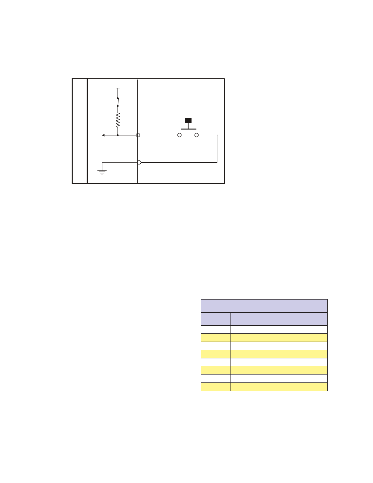
Configuring an Input
Figure 6.2 below illustrates the Input Equivalent Circuit of the Isolated I/O being used with a switch. T o
illustrate the usage of an input you will go through the steps to configure this switch to start a simple
program at Line 1000 to index a motor 200 user units. First you must configure the I/O Line 21 as a “GO”
input:
4.5V Internal
Pullup
Pull-up Switch = CLOSED
IOS 21 = 9, 0, 0
T o break this command down:
PUSH BUTTON
SWITCH
IOS 21 - Identifies the I/O Line we are
setting as 21.
I/O LINE
9 - Configures the I/O T ype to “GO”.
0 - Configures I/O as Input.
0 - Configures I/O as Active LOW .
I/O GND
LYNX Cont rol Module
When the Input T ype “GO” is selected
it will always look to execute a
program located at line 1 of program
memory . Therefore, to run a program at
Figure 6.2: Isolated I/O Input
line 1000 you must do the following:
PGM 1 ‘Records program at line 1 of memory space
EXEC 1000 ‘Execute program located at line 1000 of memory space
END ‘Terminates Program
PGM ‘Switches system back to immediate mode
PGM 1000 ‘Records program at line 1000 of memory space
MOVR 200 ‘Move relative to current position 200 user units
HOLD 2 ‘Hold program execution until specified motion is
‘completed
END
PGM
Configuring the Digital Filtering
User definable Digital filtering makes the L YNX well
suited for noisy industrial environments. The filter
setting is software selectable using the IOF
Variable with a minimum guaranteed detectable
pulse width of 18 microseconds to 2.3 milliseconds.
The table below illustrates the IOF settings.
The filter setting will reject any frequency above
the specified bandwidth. For example:
IOF 2 = 3 ‘Set the Digital
Filter for I/O Group 20 to
3.44kHz
This setting will cause any signal above 3.44 kHz on
I/O lines 21-26 to be rejected. The default filter
setting for the isolated I/O groups is 7, or 215Hz.
O/IdetalosIesopruPlareneGehtrofsgnitteSretliFFOI
esluPelbatceteDmuminiM
htdiW
gnitteSretliF
0zHk5.72sdnocesorcim81
1 zHk7.31 sdnocesorcim63
2zHk98.6sdnocesorcim37
3 zHk44.3 sdnocesorcim541
4zHk27.1sdnocesorcim092
5 zH068 sdnocesorcim185
6zH034sdnocesillim261.1
)tluafed(7 zH512 sdnocesillim323.2
ffotuC
ycneuqerF
)7-0=>mun<(>mun<=FOI
Table 6.3: Digital Filter Settings for the Isolated I/O
1 - 28 Modular LYNX System 12.05.2003
Page 29

Configuring an Output
Figure 6.3 illustrates the Output equivalent circuit of the Isolated I/O. When used as an output the I/O line is
able to sink 350mA continuous for each output, or a total of 1.5A for the entire I/O Group. See Section 9:
The Isolated Digital I/O Module for detailed specifications. In the usage example we will use an LED on I/O
Line 31 for the load. W e will use the same program from the input example, only we will use the output to
light the LED while the motor is
moving.
Modular L YNX System
IOS 31 = 18, 1, 1
Using the table on page 27 we can
break this setting down as follows:
IOS 31 - Identifies that I/O line 31 is
being configured.
4.5V Internal
Pullup
Pull-Up Sw itch = OPEN
+5 VDC
18 - Configures the I/O Type as
“Moving”.
1 - Configures the I/O line as an
7.5k
output.
1 - Configures the Line as “Active
HIGH”.
LYNX Co ntrol Module
Ω
I/O LINE
Now when the input program above is
executed, the LED will be lit during the
move.
Figure 6.3: Isolated I/O Output
The IO Variable
After configuring the I/O by means of the IOS variable, we need to be able to do two things with the I/O.
1] Write to an output, or group of outputs, thus setting or changing its (their) state.
2] Read the states of either inputs or outputs. We can use this information to either display those
states to our terminal, or to set up conditions for branches and subroutine calls within a program.
We can also use this command to write or read the state of an entire I/O group.
Read/Write a Single I/O Line
T o read the state of a single input or output, the following would be typed into the terminal:
PRINT IO 21
The response from this would be 1 or 0, depending on the state of the line.
The state of an input or output in a program can be used to direct events within a LYNX program by either
calling up a subroutine using the “CALL” instruction, or conditionally branching to another program
address using the “BR” instruction. This would be done in the following fashion.
CALL MYSUB, IO 22=1
This would call up a subroutine labled “MYSUB” when I/O line 21 is active.
BR 200, IO 22=0
This would branch to address 200 when I/O line 22 is inactive.
Writing to an output is accomplished by entering the following into a terminal or program:
IO 21=1
IO 21=0
This would change the state of I/O line 21.
Modular LYNX System 12.05.2003
1 - 29
Page 30

Read/Write an I/O Group
When using the IO variable to read the state of a group of
inputs/outputs, or write to a group of outputs you would first
want to configure the entire I/O group to be general purpose
inputs or outputs using the IOS variable. In this case the
response or input won’t be a logic state of 1 or 0, but rather the
decimal equivalent (0 to 63) of the 6 bit binary number represented by the entire group.
When addressing the I/O as a group the LSB (Least Significant
Bit) will be line 1 of the group, (e.g. 21, 31, 41, 51). The MSB
(Most Significant Bit) will be line 6 of the group (e.g. 26, 36, 46,
56).
The table on the left shows the bit weight of each I/O line in the
group. It also illustrates the state should 6 LED’s be connected
to I/O group 20 when entering the IO variables in this exercise.
Configure the IOS variable such that group 20 is all general
purpose outputs, active low or:
IOS 20 = 0,1,0
Enter the following in the terminal:
IO 20 = 35
BIT WEIGHT DISTRIBUTION TABLE
I/O 26
MSB
32
111
I/O 26
MSB
011
I/O 26
MSB
FOR GROUP 20 I/O
I/O 21
I/O 22I/O 23I/ O 24I/ O 25
16 8
BINARY STATE OF I/ O GROUP 20
IO 20 = 35
4
21
000
I/O 21
I/O 22I/O 23I/ O 24I/ O 25
BINARY STATE OF I/ O GROUP 20
IO 20 = 7
001
I/O 21
I/O 22I/O 23I/ O 24I/ O 25
BINARY STATE OF I/ O GROUP 20
IO 20 = 49
LSB
LSB
LSB
As shown in the table I/O lines 26, 22 and 21 should be illuminated, 25, 24 and 23 should be off.
Enter this next:
IO 20 = 7
Now I/O 21, 22 and 23 should be illuminated.
IO 20 = 49
I/O 26, 25, and 21 are illuminated.
NOTE: You can only write to General Purpose Outputs. If you
attempt to write to and input or dedicated output type an error
N
will occur!
100
101
I/O 26
MSB
Table 6.4: Binary State of Outputs
I/O 21
I/O 22I/O 23I/ O 24I/ O 25
LSB
1 - 30 Modular LYNX System 12.05.2003
Page 31

The Differential I/O
The Clock Interface
Quadrature
Channel A
Channel B
Step Clock/Direction
Step Clock
Direction
Up/Down
CW
CCW
Figure 6.4: Clock Functions
The LYNX has four clock pairs that are used by the high speed I/O. One of these, clock
pair 11 and 12, is fixed as an output and is used internally to provide step clock and
direction pulses to Step Clock and Direction outputs located on Connector P1 of the
L YNX Controller . The step clock output increments CTR1 (Counter 1). CTR1 may be
read from or written to by software instructions in either program or immediate mode.
The following table explains the clocks, as well as their default I/O line pair placement.
Clock Types Defined
There are three basic types of clocks that may be configured for the LYNX, they are:
1] Quadrature
2] Step/Direction
3] Up/Down
These clock functions are illustrated in figure 6.4.
Quadrature
The quadrature clock function is the most commonly used input clock function. This is
the default setting for each high speed I/O channel except 11 & 12. This clock function
will typically be used for closed loop control (encoder feedback) or for following
applications
Modular L YNX System
Step/Direction
The step/direction clock funtion would typically be used in an application where a secondary or tertiary
clock output is required to sequentially control an additional axis.
Up/Down
The up/down clock type would typically be used as an output function where a secondary axis is being
driven by a stepper or servo drive with dual-clock direction control circuitry .
skcolCruoFehT
#kcolC riaPeniLO/I noitisoPtolS retnuoC noitcnuF
.kcolcnoitomdetarenegyllanretnisikcolcsihT
121&11enoN1RTC
2 41&31 2tolS 2RTC
361&513tolS3RTC
71 2tolS enoN
4
81 3tolS enoN
.rotcennoclanretxeynano
.1KLCotderaegyllacinortcele
.kcolc
.kcolc
otlortnoclanoitceriddnakcolcpetssedivorptI
elbaliavatonsikcolcsihT.noitcesrevirdeht
yB.tuptuorotupninasaderugifnocebyaM
.tupnierutardauqasaderugifnocsisihttluafed
kcolcyradnocesasaderugifnocebnactI
.1KLCotderaegyllacinortceletuptuo
yB.tuptuorotupninasaderugifnocebyaM
.tupnierutardauqasaderugifnocsisihttluafed
tuptuokcolcyraitretasaderugifnocebnactI
narotupnideepshgihasaderugifnocebyaM
ecnereferzHM1asitituptuonasA.tuptuo
rotupnideeshgihasaderugifnocebyaM
ecnereferzHM01asitituptuonasA.tuptuo
Modular LYNX System 12.05.2003
Table 6.5: The Four Clocks and Their Default Line Placement
1 - 31
Page 32

Configuring The Differential I/O - The IOS Variable
The high speed differential I/O is configured by means of the IOS variable, and is used in the the same
fashion in which the isolated I/O is configured. The main difference lies in that there are three additional
parameters which need to be set in configuring the triggering, clock type, and ratio mode setting.
It is important to note that the high speed differential I/O lines may be used for the same input or output functions
as the isolated digital I/O where the higher speed capabilities of the differential I/O is required. However, for
purposes of this example we will only illustrate the clock functions associated with the high speed differential I/O.
Figure 6.5 following illustrates the IOS variable settings for the high speed differential I/O.
Enter the Ch ann el # (13-18) here!
IOS = , , , , ,
Enter I/O Line Type # Here
1 = Clock 1A
2 =
Clock 1B
3 =
Clock 2A
4 =
Clock 2B
5 =
Clock 3A
6 =
Clock 3B
7 =
Clock 4A
8 =
Clock 4B
NOTE: The
Clock #’s are
fixed to the ir
asso ciated I/O
channel an d
cannot be
changed! They
are entered for
sake of consistency
only!
Set the Tr iggering
0 = Level
1 = Edge
XXXX X XXX
Define the Clock Type
0 = Not A Clock
1 = Quadrature
2 = Step/Direction
3 = Up/Down
Define Line or Group
As Input or Outp ut
0 = Input
1 = Output
Set the state
of the Line or Group
0 = Active Low
1 = Active Hig h
Set the Ratio Mode
0 = No Ratio
1 =Ratio
Figure 6.5: IOS Variable Settings for the High Speed Differential I/O
Configuring an Input
Clocks 2, 3 and 4 can be configured as high speed inputs, or as a general purpose input in the same fashion
as the Isolated I/O. In configuring the Differential I/O line as a general purpose input you would typically
use the “+” line of the line pair. You cannot use both lines as separate I/O lines. The figure below shows the
Input Equivalent Circuit with the I/O line pair connected to channel A of a differential encoder . This feature
+5VDC
Differential
Encoder
Channel A (+)
Channel A (-)
Channel B (+)
Channel B (-)
Index (+)
Index (-)
High Speed Differential I/O Module
Edge
Level
Edge
Detect
Logic
Polarity
Digital
Filter
Group
Filter
Setting
10k
Ω
4.3V
+
1.4V
-
4k
Ω
3.3k
20k
Ω
Input (+)
Input (-)
Ω
Figure 6.6: Differential I/O Input Equivalent Circuit
1 - 32 Modular LYNX System 12.05.2003
Page 33

is demonstrated in
Typical Functions of the Differential I/O: Connecting and Using an Encoder. Clocks 2, 3
and 4 are set up as Quadrature inputs by default. The defaults for each I/O Line Pair are:
IOS 13 = 3, 0, 1, 0, 1, 0
IOS 14 = 4, 0, 1, 0, 1, 0
IOS 15 = 5, 0, 1, 0, 1, 0
IOS 16 = 6, 0, 1, 0, 1, 0
IOS 17 = 7, 0, 1, 0, 1, 0
IOS 18 = 8, 0, 1, 0, 1, 0
Setting the Digital Input Filtering for the Differential I/O
Modular L YNX System
User definable Digital filtering
makes the L YNX well suited for
noisy industrial environments.
The filter setting is software
selectable using the IOF
Variable with a minimum
guaranteed detectable pulse
width of 18 microseconds to 2.3
milliseconds. The table (right)
illustrates the IOF settings.
gnitteSretliF
)tluafed(0zHM00.5sdnocesonan001
1 zHM05.2 sdnocesonan002
2zHM52.1sdnocesonan004
3 zHk526 sdnocesonan008
4zHk313sdnocesorcim6.1
5 zHk651 sdnocesorcim2.3
6zHk1.87sdnocesorcim4.6
7 zHk1.93 sdnocesorcim8.21
ffotuC
ycneuqerF
)7-0=>mun<(>mun<=FOI
htdiW
Table 6.6: Digital Filter Settings for the Differential I/O
Configuring an
Output
The Differential I/O Group 10 has 3 Channels (Line Pairs 13 & 14, 15 & 16, and 17 & 18) that can be configured as an output by the user and One Channel (Line Pairs 11 & 12) that is configured as output only. (SCK
and DIR on the Control Module.) These outputs can be configured as high speed outputs or 0 to 5VDC
general purpose outputs by using the IOS variable. The high speed clock outputs have the following
restrictions:
O/IlaitnereffiDdeepShgiHehtrofsgnitteSretliFFOI
esluPelbatceteDmuminiM
Line Pairs 11/12, 13/14 and 15/16 can be configured to Step Clock/Direction or Up/Down.
Line Pair 17/18 is limited to 1MHz Reference Out (17) and 10MHz Reference Out (18).
Clock
User
Defined
Function
High Speed Differential I/ O Module
Modular LYNX System 12.05.2003
+5VDC
IOS
10k
4k
Ω
Ω
3.3k
20k
Ω
Output (+)
Output (-)
Ω
Output (+)
Figure 6.7: Differential I/O Output Equivalent Circuit
Secondary
Drive
Step Clock
Direction
1 - 33
Page 34

In the Equivalent Circuit in Figure 6.7 an Output is being used as Step or Direction on a driver.
For the configuration example, use I/O line 13 for the output. Since by default the line is a quadrature input
we must configure it to be a Step/Direction Output by setting the IOS Variable to the following:
IOS 13 = 3, 1, 0, 1, 2, 0
This breaks down as:
IOS 13 - Identifies the line being configured as 13.
3 - Sets the I/O T ype to Clock 2A (default).
1 - Sets it as an output.
0 - Sets Logic at Low True.
1 - Edge Triggered.
2 - Sets the Clock T ype to Step/Direction.
0 - No Ratio.
Typical Functions of the Differential I/O
Connecting and Using an Encoder
The differential I/O module can be set up to receive encoder feedback using either a differential or a single
ended output encoder. A differential output encoder would typically be connected to differential input pairs
13 and 14 (P1, pins 1 – 4) as the default setting for I/O 13 and 14 is set up to accept a quadrature encoder
input. Channel A of the encoder would be connected to input pair 13 (P1, pins 1 & 2) and channel B would
be connected to input pair 14 (P1, pins 3 & 4). A single ended output encoder would be connected to the
positive inputs of the input pair. Whether you use a differential encoder or single ended encoder the same
software commands and settings will be used.
In setting up your system to run with an encoder you will be using the following variables, flags, and
instructions. The variables used with an encoder will be MUNIT, EUNIT, CTR2, and POS. The Encoder
Enable Flag EE, and the instruction MOVR will be used. The block diagram to the left illustrates a L YNX
system with the encoder and drive connections that will be used in this example.
The sequence of commands (in bold) used to make this setup function would be as follows:
‘Set the MUNIT V ariable to 51,200 steps/rev
MUNIT = 51200
‘Set encoder enable to TRUE (1), default value = F ALSE (0)
EE = 1
‘Set the EUNIT (Encoder Units) variable to 800 (200 [Encoder Resolution] X 4 [Quadrature Input])
This means that 1 unit of motion, or 1 POS, is equal to 800 encoder counts. In this instance it will be
1 rotation of the motor.
EUNIT = 800
‘Save the above flag and variable settings
SAVE
Now you may begin to use the motion command MOVR, as well as PRINT POS and PRINT CTR2 to see the
number of encoder counts fed back to the system.
‘Set the motor position to 0
POS = 0
‘Move the motor 2 units (2 X EUNIT) relative to current position.
MOVR 2
‘Print the value of CTR2. This value will indicate the number of encoder counts that the motor has
moved. Y our terminal should echo back the number “1600”.
1 - 34 Modular LYNX System 12.05.2003
Page 35

PRINT CTR2
‘Print the position of the motor. Your terminal should echo “2.000”
PRINT POS
By printing the variable CTR2 (CTR2 = EUNIT X POS) we can view the distance the motor has traveled in
raw encoder counts, or by printing POS you can see the distance of travel represented by number of units
relative to 0.
HSIO ENCODER
13- Channe l A13+ Ch anne l A+
14- Chann el B14+ Channel B+
Stepping Motor
+5VDC
Encoder
GND
&
SCLK+
DIR+
+5VDC
OUTPUT
123456 123456
A0
A1
A2
PT
HI
123456
UG
DIR-
DIR+
SCKSCK+
GND
+5V
RX-
RX+
TXTX+
CGND
RX
TX
GND
V+
21
22
23
24
25
26
21
22
23
24
25
26
31
32
33
34
35
36
IG
32
33
34
35
36
TM
TM
Differential/O MODULE
1313+
1414+
1515+
1616+
1717+
1818+
GD
31
Modular L YNX System
+5VDC Opto Supply
ZN429D
GP59627A
Step Clock Input
Direction Input
GP59627A
Power Connectio ns
Not Shown For
ZN429D
Simplification
Motor Driver
Figure 6.8: Connecting and Using an Encoder
Translating the EUNIT Variable to a Dimension of Distance
The EUNIT, or Encoder Unit variable, is the scaling factor used to translate Encoder steps to a dimension of
distance, or user units. At this point you should already be familiar with the MUNIT variable. The main
difference between the two is as follows: By using MUNIT scaling factor you monitor the position of an axis
based upon the value of CTR1, the register that contains the actual count of clock pulses sent to the drive.
The number of pulses is then scaled to user units by setting the MUNIT Variable to the appropriate scaling
factor for the type of units being used, be they inches, millimeters, degrees, etc. Then the POS variable
tracks position in the user units specified. Example:
User Unit (POS) = CTR1 ÷ MUNIT where EE (Encoder Enable) Flag = F ALSE (0)
By setting the state of EE, the master encoder function enable flag, to a true state you will monitor the
position of an axis based upon the actual position of the motor shaft as it is fed back to the Control Module
Modular LYNX System 12.05.2003
1 - 35
Page 36

by a motor mounted encoder. The actual count of encoder pulses received by the Control Module is
maintained by the register
variable scaling it to user units. Example:
User Unit (POS) = CTR2 ÷ EUNIT where EE (Encoder Enable) Flag = TRUE(1)
When using the EUNIT scaling factor it is important to understand that you MUST set the EUNIT variable
AND the MUNIT variable to the same scaling factor for accurate position monitoring. In the example below
you will use a hypothetical system designed from the following components:
An IMS IB462H Half/Full Step driver configured for Half Step Operation.
A 1.8° Stepping Motor mounted to a 20cm linear slide.
A 200 Line Encoder.
Y ou will want to use millimeters for our user unit. The IB462H in half step mode will need 400 clock pulses to
turn the motor one revolution. The pitch on the leadscrew is such that one millimeter of linear motion will
require 25 clock pulses. 400 steps/rev ÷ 25 steps/mm = 16 mm/rev . Therefore, you would set the MUNIT
variable as follows:
Now, when you give a MOVR 20 instruction, the axis will index 20 millimeters. Now to set the EUNIT
Variable. W e have a 200 line encoder connected to a quadrature clock input. This will mean that 1 revolution
will equal 800 Encoder Pulses, you will have to use the same scaling factor as we did for MUNIT as there will
still be 16mm per revolution:
CTR2, (if the encoder is connected to I/O line pair 13 &14) with the EUNIT
MUNIT = 400/16
EUNIT = 800/16
Both values must be set, and both must be set to the same scaling factor. W ith the EE = 1 a MOVR 20
command will still index the axis 20 millimeters, but position will be maintained by CTR2.
Half Axis Operation (Follower)
In half axis mode the master clock is taken from a clock input 2, 3 or 4 (line pairs 13-14, 15-16 or 17-18) which
have been set for input, clock type and ratio enabled. This is the factor at which the count rate out to the
primary drive will follow the external clock in half axis mode. This clock input would typically be connected
to differential input pairs 15 and 16 (P1, pins 5 – 8). This could be set up as any of the available clock types.
If half axis mode is enabled (HAE), the primary axis of the control will follow the clock input with the ratio
specified by the HAS variable.
In order to use the HAS (Half axis mode scaling) variable the HAE flag must be set to true (1). For example,
to set the half axis scale factor to .5, where the drive will follow the external Clock input with a ratio of 1
count to the drive for every two counts from the external clock, you would use the command: SET HAS = .5
(or HAS = .5). Figure 6.9 illustrates the connections for using this mode of operation using a clock input
from an encoder.
The sequence of commands used to make this setup function would be as follows:
‘Set IOS 15 to ratio mode
IOS 15 = 5,0,1,0,1,1
‘Set IOS 16 to ratio mode
IOS 16 = 6,0,1,0,1,1
‘Half axis enable set to true
HAE = 1
‘Half axis scaling to .5 (1 output clock pulse to every 2 input clock pulses)
HAS = .5
1 - 36 Modular LYNX System 12.05.2003
Page 37

y
SCLK+
DIR+
+5VDC
OUTPUT
Modular L YNX System
HSIO ENCODER
123 456 123456
A0
A1
A2
PT
HI
123456
UG
DIRDIR+
SCK-
SCK+
GND
+5V
RX-
RX+
TXTX+
CGND
RX
TX
GND
V+
21
22
23
24
TM
25
Differential/O MODULE
26
21
22
23
24
25
26
31
32
33
34
35
36
IG
31
32
33
34
35
36
TM
1313+
1414+
1515+
1616+
1717+
1818+
GD
13+ Channel A
14+ Ch ann el B
Encoder or
Pulse Generator
Stepping
Motor
+5VDC Opto Suppl
ZN429D
GP59627A
Step Clock Input
Direction Input
GP59627A
Power Connections
Not Shown For
ZN429D
Simplification
Motor Driver
Figure 6.9 Half Axis Mode (Following)
NOTE: The HAS variable must be set to less than 1 or Error
Code 9004, “Ratio Out of Range” will occur.
N
One and a Half Axis Operation (RATIOE)
A secondary drive can be connected to a pair of differential outputs. The secondary driver will operate off
of the differential output pair 15 and 16 (I/O pair 13 and 14 can also operate in this mode). Setting the
ratio mode to TRUE (1) for the differential output clock (IOS) specifies a secondary drive function. Then
when ratio mode is enabled (RATIOE); the secondary axis will follow the primary axis with the ratio
specified by the RATIO variable.
The sequence of commands used to make this setup function would be as follows:
‘Set IOS 15 to step/direction clock type, and ratio mode
IOS 15 = 5,0,1,0,2,1
‘Set IOS 16 to step/direction clock type, and ratio mode
IOS 16 = 6,0,1,0,2,1
‘Set Ratio Mode Enable Flag to TRUE (1)
Modular LYNX System 12.05.2003
1 - 37
Page 38

RATIOE = 1
‘Set RA TIO variable to .5 for the secondary drive
RATIO = .5
With this setup, the motor on the secondary drive will move half the distance of the primary.
SCLK+
DIR+
+5VDC
OUTPUT
123456 123456
A0
A1
A2
PT
HI
123456
UG
DIR-
DIR+
SCKSCK+
GND
+5V
RXRX+
TXTX+
CGND
RX
TX
GND
V+
21
22
23
24
25
26
21
22
23
24
25
26
31
32
33
34
35
36
IG
31
32
33
34
35
36
TM
TM
Differential/O MODULE
1313+
1414+
1515+
1616+
1717+
1818+
GD
+5VDC Opto Supply
HSIO DRIVE #2
13+ Step Clock
14+ Direction
+5VDC
Opto Supply
ZN429D
GP59627A
Motor Drive #2r
ZN429D
GP59627A
ZN429D
GP59627A
Stepping
Motor #2
Step Clock In put
Direction Input
GP59627A
Stepping Motor
ZN429D
Power Connections
Not Shown For
Motor Driver
Simplification
Figure 6.10: One and a Half Axis Operation
NOTE: The RATIO variable must be set to less than 2 or -2 or
Error Code 9004, “Ratio Out of Range” will occur.
N
1 - 38 Modular LYNX System 12.05.2003
Page 39

Section 7
The LYNX Control Module (LX-CM100-000)
Section Overview
This section will cover:
! Hardware Specifications
! Environmental Specifications
! Mechanical Specifications
! Power Requirements
! Connection Overview
! LED Indicators
! Pin Assignments
! Switch Assignments
Hardware Specifications
Modular L YNX System
Environmental Specifications
Ambient Operating T emperature.............................................. 0 to +50 degrees C
Storage T emperature ................................................................ -20 to +70 degrees C
Humidity .................................................................................. 0 to 90% non-condensing
Mechanical Specification
Dimensions in Inches (mm)
2.71 max
(68.8)
1.52 max
(38.6
ON
ON
ON
0.41
(10.5)
2.93
(74.4)
0.39
(9.9)
4.39 max
(111.5)
3.75 max
(95.3)
0.29
(7.4)
2.13
(54.1)
Modular LYNX System 12.05.2003
NOTE: All dimensions nominal unless otherwise specified.
Figure 7.1: LYNX Control Module Dimensions
1 - 39
Page 40

Power Requirements
egatloVtupnI%5±CDV5+rodetalugernUCDV57+ot21+
snoitacificepSdnastnemeriuqeRrewoP
)tupniCDV5(Am052
tnerruCtupnI
egatloVtuptuO%5±CDV5+
tnerruCtuptuO detimiLyllanretnI(Am051
Table 7.1: Power Requirements for the LYNX Control Module
Connection Overview
Party Mode Address
Switches Select Addresses
"A" through "G"
Party Mode Select
Host Interface Mode Select
Software Upgrade
Differential Direction I/O 11
and Step Clock (I/O 12) Outputs
Current Limited +5V Output
or +5V Power In
P2
RS-485
Serial
Communications
RS-232
*)tupnICDV21+(Am561
*)tupnICDV84+(Am0.59
*)tupnICDV57+(Am5.48
INTELLIGENT MOTION SYSTEMS, INC.
A0
A1
A2
PT
HI
UG
DIRDIR+
SCK-
SCK+
GND
+5V
RX-
RX+
TX-
TX+
CGND
RX
TX
FAULT
ON ON
123456
POW
123456 123456
ER
21
22
23
24
25
26
31
32
33
34
35
36
IG
)ylnOeludoMlortnoC(dedaolnutuptuoCDV5+dnaO/I*
21
22
23
24
25
26
+5 V Pull-up Enable
Switches for
I/O Group 20
Group 20
+5 to +24 VDC I/O
P3
Group 30
+5 to +24 VDC I/O
Isolated Ground
31
32
33
34
35
36
+5 V Pull-up Enable
Switches for
I/O Group 30
P1
Power Ground
+12 to +75 VDC Input Power
GND
ON
V+
TM
Figure 7.2: LYNX Control Module, Switches and Connections
1 - 40 Modular LYNX System 12.05.2003
Page 41

LED Indicators
roloCDEL gninaeM
neerGnOrewoP
Modular L YNX System
deR
TLUAF
Table 7.2: LYNX Control Module LED Indicators
Pin Assignment and Description
#niP noitcnuF noitpircseD
1dnuorGrewoP.ylppusrewopdetalugernuehtrofdnuorgrewoP
2
#niP noitcnuF noitpircseD
1)11O/I(-noitceriD
2 )11O/I(+noitceriD .evobanoitpircsedeeS
3)21O/I(-kcolCpetS
4 )21O/I(+kcolCpetS .evobanoitpircsedeeS
5)DNG(dnuorG
6 CDV5+
7tupnI-XR584-SR
8 tupnI+XR584-SR .evobanoitpircsedeeS
9tuptuO-XT584-SR
01 tuptuO+XT584-SR .evobanoitpircsedeeS
11
21 tupnIXR232-SR
31tuptuOXT232-SR
detalugernU
ylppuSrewoP
)+V(tupnI
Table 7.3: LYNX Control Module Connector P1 Pin Configuration
.tupninasademmargorp
.tupninasademmargorp
ecafretnIsnoitacinummoCehT:5 .
ecafretnIsnoitacinummoCehT:5 .
snoitacinummoC
)DNGC(dnuorG
ees,noitamrofni ecafretnIsnoitacinummoCehT:7noitceS
ecafretnIsnoitacinummoC .
ecafretnIsnoitacinummoC .
narevenehwdetanimulliotDELehtesuaclliw)1(EURT=TLUAF.galf RORRE .srucco
ehtgnittesybrotacidniehtelbasidroelbaneotesoohcnacresuehT.detcetedtluaferawtfosrometsyS
noitcennoCrewoPtupnI:lanimreTkcoLwercSnoitisoPowT-1P
.desuebotsiylppusrewoplanretxenafitupnirewopdetalugernuCDV57–21
snoitacinummoCdnarewoPdetalugeR,slangiSnoitoM:rotcennoClanimreTelbaevomeRnoitisoP31-2P
sihtroftluafedehT.11O/Iro1#,1puorgroflangisdereffubyllaitnereffidehtera2dna1sniP
yamlangissiht,derisedfI.rellortnocehtfoevirdrotomyramirpehtroftuptuonoitceridehtsilangis
ebtonyamO/IsihT.tuptuoresuaroepytkcolcnwod/puroerutardauqasademmargorpeb
sihtroftluafedehT.21O/Iro2#,1puorgroflangisdereffubyllaitnereffidehtera4dna3sniP
langissiht,derisedfI.rellortnocehtfoevirdrotomyramirpehtroftuptuokcolcpetsehtsilangis
ebtonyamO/IsihT.tuptuoresuaroepytkcolcnwod/puroerutardauqasademmargorpebyam
rofnruterlangisasadedivorpsisihT.1Protcennocfo1nipnodnuorgrewopehtotnommoC
.6nipnotuo/niCDV5ehtrofnruterrewopehtdnaslangislortnocnoitomeht
lanimretsiht,1ProtcennocaivderewopsieludomlortnocehtnehW.tuoronistlov5ebnacsihT
,derisedfI.sredocnesahcusstiucricresurofCDV5detalugerfoam051otpusedivorp
yllufatahtdetonebdluohstI.noitcennoctupnirewopasadesuebyamlanimretsiht,revewoh
.ylppusCDV5sihtmorftnerrucam008otpueriuqeryammetsysXNYLderugifnoc
yehT.ecafretnisnoitacinummoc584-SRehtrofstupnieviecerlaitnereffidehtera8dna7sniP
ees,noitamrofninoitcennoccificepsroF.desutonerayehtfidetcennocsidtfelebdluohs noitceS
yehT.ecafretnisnoitacinummoc584-SRehtrofstuptuotimsnartlaitnereffidehtera01dna9sniP
ees,noitamrofninoitcennoccificepsroF.desutonerayehtfidetcennocsidtfelebdluohs noitceS
noitcennoccificepsroF.232-SRdna584-SRhtobroflangisdnuorgsnoitacinummocdetalosI
.
ees,noitamrofninoitcennoccificepsroF.retupmoctsohehtmorftupnievieceR ehT:5noitceS
ees,noitamrofninoitcennoccificepsroF.retupmoctsohehtottuptuotimsnarT ehT:5noitceS
Table 7.4: LYNX Control Module Connector P2 Pin Configuration
Modular LYNX System 12.05.2003
1 - 41
Page 42

#niP noitcnuF noitpircseD
O/IlatigiDdetalosI:rotcennoClanimreTelbaevomeRnoitisoP31-3P
ehtni cnerefeRerawtfoS:3traP dnaelbitapmoclevelcigolSOMCerastupnI.)launamsihtfoe
8-1
21-7
31dnuorGO/IdetalosI
02puorGO/I
62-12seniL
03puorGO/I
63-13seniL
Table 7.5: LYNX Control Module Connector P3 Pin Configuration
Switch Assignments
#hctiwS noitcnuF noitpircseD
1edargpUerawmriF .margorpedargpuSMIehtgnisudedargpuebyamerawmrifrellortnoceht,nosihctiwssihtnehW
2 ecafretnItsoH
3edoMytraP
4
5
6
sserddAedoMytraP
0A-0tiB
sserddAedoMytraP
1A-1tiB
sserddAedoMytraP
2A-2tiB
ecafretnI .
ehtfonoitpircsedees(stuptuorostupnisaelbammargorpyllaudividnieraslangiS dnammocSOI
nepoerastuptuO.gniretliflatigidaivelbaliavasinoitcejeresioN.stlov82otstupnitpeccanac
.snoitacificepsdnaegasurof
otrefeR.sdaoltnecsednacniroevitsiser,evitcudnihctiws O/IlatigiDehtgnirugifnoC:6noitceS
.evobanoitpircsedeeS
.sdnuorgnoitacinummoc
ees,noitamrofnieromroF.ecafretnitsohehtsa ecafretnIsnoitacinummoCehT:5noitceS
ehtyberawtfosnineddirrevoebyamhctiws .galfTSOH
ees,noitamrofnieromroF.detcelessisnoitacinummoc snoitacinummoCehT:5noitceS
oslaeeS.sserddaedonsnoitacinummocedomytrapsteS noitcurtsniND ecnerefeRerawtfoSehtni
sserddA0A1A2A
enoNFFOFFOFFO
"A"NOFFOFFO
"B"FFONOFFO
"C"NONOFFO
"D"FFOFFONO
"E"NOFFONO
"F"FFONONO
"G"NONONO
nacstuptuO.CDV5otsrotsiserpullupmhoK5.7elbahctiwsyllaudividnievahhcaesO/I.niard
dnarewopehtmorfdetalosI.O/I03dna02spuorgrofnruterlangisnommocdetalosI
sgnitteSerawtfoSybneddirevOebtaM.teseRmetsySronO-rewoPtadaeR:sehctiwSnoitarugifnoC
nisnoitacinummocrofrellortnoCecafretnItsoHehtsatcalliwrellortnoceht,nosihctiwssihtnehW
tcatonlliwdnametsysehtnievalsasirellortnoceht,ffositinehW.metsysrellortnocelpitluma
sihT.
edomelgnis,ffositinehW.detcelessisnoitacinummocedomytrap,nosihctiwssihtnehW
Table 7.6: LYNX Control Module Configuration Switches
stupnIgnisicrexErofelbasU,emiTynatadegnahCeBnaC:sehctiwSpU-lluPO/I02puorG
#hctiwS noitcnuF noitpircseD
6-1
sehctiwSlaudividnI
02puorGO/Irof
.spU-lluP
..erawtfosmetsysgnitsetelihwtupninafonoitavitcaehtetalumisotdesueb
naC.CDV5otrotsisermhoK5.7lanretninahguorhtpudellupsiO/Ieht,nosihctiwssihtnehW
Table 7.7: LYNX Control Module Group 20 I/O Pull-up Switches
stupnIgnisicrexErofelbasU,emiTynatadegnahCeBnaC:sehctiwSpU-lluPO/I03puorG
#hctiwS noitcnuF noitpircseD
6-1
sehctiwSlaudividnI
03puorGO/Irof
.spU-lluP
..erawtfosmetsysgnitsetelihwtupninafonoitavitcaehtetalumisotdesueb
naC.CDV5otrotsisermhoK5.7lanretninahguorhtpudellupsiO/Ieht,nosihctiwssihtnehW
Table 7.8: LYNX Control Module Group 30 I/O Pull-up Switches
1 - 42 Modular LYNX System 12.05.2003
Page 43

Section 8
The LYNX Control Module (Combination)
Section Overview
The Control Module (Combination) (IMS Part # LX-CM200-000) offers the user of purchasing a L YNX
Control Module with 3 differential I/O Channels and 6 Isolated I/O lines instead of the standard 2 Isolated
I/O groups. This section will cover:
! Hardware Specifications
! Environmental Specifications
! Mechanical Specifications
! Power Requirements
! Connection Overview
! LED Indicators
! Pin Assignments
! Switch Assignments
Modular L YNX System
Hardware Specifications
Environmental Specifications
Ambient Operating T emperature.............................................. 0 to +50 degrees C
Storage T emperature ................................................................ -20 to +70 degrees C
Humidity .................................................................................. 0 to 90% non-condensing
Mechanical Specification
Dimensions in Inches (mm)
2.71 max
(68.8)
1.52 max
(38.6)
0.41
(10.4)
1313+
1414+
1717+
21
22
23
24
25
26
IG
21
22
23
24
25
26
2.93
(74.4)
0.39
(9.9)
4.39 max
(111.5)
3.75 max
(95.3)
0.29
(7.4)
2.13
(54.1)
Figure 8.1: LYNX Control Module (Combination) Dimensions
Modular LYNX System 12.05.2003
NOTE: All dimensions nominal unless otherwise specified.
1 - 43
Page 44

Power Requirements
egatloVtupnI%5±CDV5+rodetalugernUCDV57+ot21+
snoitacificepSdnastnemeriuqeRrewoP
)tupniCDV5(Am052
tnerruCtupnI
egatloVtuptuO%5±CDV5+
tnerruCtuptuO detimiLyllanretnI(Am051
T able 8.1: Power Requirements for the LYNX Control Module (Combination)
Connection Overview
Party Mode Address
P2
P1
Switches Select Addresses
Host INterface Mode Select
Differential Direction I/O 11
and Step Clock (I/O 12) Outputs
Current Limited +5V Output
Communications
+12 to +75 VDC Input Power
"A" through "G"
Party MOde Select
Software Upgrade
or +5V Power In
RS-485
Serial
RS-232
Power Ground
*)tupnICDV21+(Am561
*)tupnICDV84+(Am0.59
*)tupnICDV57+(Am5.48
INTELLIGENT MOTION SYSTEMS, INC.
A0
A1
A2
PT
HI
UG
DIR-
DIR+
SCKSCK+
GND
+5V
RX-
RX+
TX-
TX+
CGND
RX
TX
GND
V+
FAULT
ON ON
123456
POW
ER
ON
1313+
1414+
1717+
21
22
23
24
25
26
IG
123456
TM
)ylnOeludoMlortnoC(dedaolnutuptuoCDV5+dnaO/I*
Group 10
Differential I/O
Channels 13, 14,
and 17
P3
Group 20
+5 to +24 VDC I/O
Isolated Ground
21
22
23
24
25
26
+5 V Pullup Enable
Switches for
I/O Group 20
Figure 8.2: LYNX Control Module (Combination) Connections and Switches
1 - 44 Modular LYNX System 12.05.2003
Page 45

LED Indicators
roloCDEL gninaeM
neerGnOrewoP
Modular L YNX System
deR
TLUAF
Table 8.2: LYNX Control Module LED Indicators
Pin Assignment and Description
#niP noitcnuF noitpircseD
1dnuorGrewoP.ylppusrewopdetalugernuehtrofdnuorgrewoP
2
Table 8.3: LYNX Combination Control Module Connector P1 Pin Configuration
#niP noitcnuF noitpircseD
1)11O/I(-noitceriD
2 )11O/I(+noitceriD .evobanoitpircsedeeS
3)21O/I(-kcolCpetS
4 )21O/I(+kcolCpetS .evobanoitpircsedeeS
5)DNG(dnuorG
6 CDV5+
7tupnI-XR584-SR
8 tupnI+XR584-SR .evobanoitpircsedeeS
9tuptuO-XT584-SR
01 tuptuO+XT584-SR .evobanoitpircsedeeS
11
21 tupnIXR232-SR
31tuptuOXT232-SR
detalugernU
ylppuSrewoP
)+V(tupnI
.tupninasademmargorp
.tupninasademmargorp
ecafretnIsnoitacinummoCehT:5 .
ecafretnIsnoitacinummoCehT:5 .
snoitacinummoC
)DNGC(dnuorG
ees,noitamrofni ecafretnIsnoitacinummoCehT:7noitceS
ecafretnIsnoitacinummoC .
ecafretnIsnoitacinummoC .
narevenehwdetanimulliotDELehtesuaclliw)1(EURT=TLUAF.galf RORRE .srucco
ehtgnittesybrotacidniehtelbasidroelbaneotesoohcnacresuehT.detcetedtluaferawtfosrometsyS
noitcennoCrewoPtupnI:lanimreTkcoLwercSnoitisoPowT-1P
.desuebotsiylppusrewoplanretxenafitupnirewopdetalugernuCDV57–21
snoitacinummoCdnarewoPdetalugeR,slangiSnoitoM:rotcennoClanimreTelbaevomeRnoitisoP31-2P
sihtroftluafedehT.11O/Iro1#,1puorgroflangisdereffubyllaitnereffidehtera2dna1sniP
yamlangissiht,derisedfI.rellortnocehtfoevirdrotomyramirpehtroftuptuonoitceridehtsilangis
ebtonyamO/IsihT.tuptuoresuaroepytkcolcnwod/puroerutardauqasademmargorpeb
sihtroftluafedehT.21O/Iro2#,1puorgroflangisdereffubyllaitnereffidehtera4dna3sniP
langissiht,derisedfI.rellortnocehtfoevirdrotomyramirpehtroftuptuokcolcpetsehtsilangis
ebtonyamO/IsihT.tuptuoresuaroepytkcolcnwod/puroerutardauqasademmargorpebyam
rofnruterlangisasadedivorpsisihT.1Protcennocfo1nipnodnuorgrewopehtotnommoC
.6nipnotuo/niCDV5ehtrofnruterrewopehtdnaslangislortnocnoitomeht
lanimretsiht,1ProtcennocaivderewopsieludomlortnocehtnehW.tuoronistlov5ebnacsihT
,derisedfI.sredocnesahcusstiucricresurofCDV5detalugerfoam051otpusedivorp
yllufatahtdetonebdluohstI.noitcennoctupnirewopasadesuebyamlanimretsiht,revewoh
.ylppusCDV5sihtmorftnerrucam008otpueriuqeryammetsysXNYLderugifnoc
yehT.ecafretnisnoitacinummoc584-SRehtrofstupnieviecerlaitnereffidehtera8dna7sniP
ees,noitamrofninoitcennoccificepsroF.desutonerayehtfidetcennocsidtfelebdluohs noitceS
yehT.ecafretnisnoitacinummoc584-SRehtrofstuptuotimsnartlaitnereffidehtera01dna9sniP
ees,noitamrofninoitcennoccificepsroF.desutonerayehtfidetcennocsidtfelebdluohs noitceS
noitcennoccificepsroF.232-SRdna584-SRhtobroflangisdnuorgsnoitacinummocdetalosI
.
ees,noitamrofninoitcennoccificepsroF.retupmoctsohehtmorftupnievieceR ehT:5noitceS
ees,noitamrofninoitcennoccificepsroF.retupmoctsohehtottuptuotimsnarT ehT:5noitceS
Table 8.4: LYNX Combination Control Module Connector P2 Pin Configuration
Modular LYNX System 12.05.2003
1 - 45
Page 46

#niP noitcnuF noitpircseD
O/InoitanibmoC:rotcennoClanimreTelbaevomeRnoitisoP31-3P
1-31O/I
2 +31O/I .evobanoitpircsedeeS
3-41O/I
4 +41O/I .evobanoitpircsedeeS
5-71O/I
6 +71O/I .evobanoitpircsedeeS
21-7
31
02puorGO/I
62-12seniL
roFdnuorGdetalosI
O/I02puorG
.sdnuorg
Table 8.5: LYNX Combination Control Module Connector P3 Pin Configuration
Switch Assignments
ehtfosnaemyb noitcurtsnISOI
ehtfosnaemyb noitcurtsnISOI
ehtfosnaemyb noitcurtsnISOI
eessliatedegasuroF. O/IlatigiDehtgnirugifnoC:6noitceS .
eessliatedegasuroF. O/IlatigiDehtgnirugifnoC:6noitceS .
eessliatedegasuroF. O/IlatigiDehtgnirugifnoC:6noitceS .
onoitpircsedees(stuptuorostupnisaelbammargorpyllaudividnieraslangiS dnammocSOIf
otrefeR.sdaoltnecsednacniroevitsiser,evitcudni O/IlatigiDehtgnirugifnoC:6noitceS
.noitamrofnierom
sgnitteSerawtfoSybneddirevOebtaM.teseRmetsySronO-rewoPtadaeR:sehctiwSnoitarugifnoC
derugifnocsilennahcsihT.31O/I,01puorgroflangisdereffubyllaitnereffidehtera2dna1sniP
derugifnocsilennahcsihT.41O/I,01puorgroflangisdereffubyllaitnereffidehtera4dna3sniP
derugifnocsilennahcsihT.71O/I,01puorgroflangisdereffubyllaitnereffidehtera6dna5sniP
ni
nacdnaelbitapmoclevelcigolSOMCerastupnI.)launamsihtfoecnerefeRerawtfoSehT:3traP
.niardnepoerastuptuO.gniretliflatigidaivelbaliavasinoitcejeresioN.stlov42otstupnitpecca
hctiwsnacstuptuO.CDV5otsrotsiserpullupmhoK5.7elbahctiwsyllaudividnievahhcaesO/I
rof
noitacinummocdnarewopehtmorfdetalosI.O/I02puorgrofnruterlangisnommocdetalos
#hctiwS noitcnuF noitpircseD
1edargpUerawmriF .margorpedargpuSMIehtgnisudedargpuebyamerawmrifrellortnoceht,nosihctiwssihtnehW
2 ecafretnItsoH
3edoMytraP
4
5
6
sserddAedoMytraP
0A-0tiB
sserddAedoMytraP
1A-1tiB
sserddAedoMytraP
2A-2tiB
ecafretnI .
Table 8.6: LYNX Combination Control Module Configuration Switches
#hctiwS noitcnuF noitpircseD
ehtyberawtfosnineddirrevoebyamhctiws .galfTSOH
"F"FFONONO
nisnoitacinummocrofrellortnoCecafretnItsoHehtsatcalliwrellortnoceht,nosihctiwssihtnehW
ees,noitamrofnieromroF.ecafretnitsohehtsa ecafretnIsnoitacinummoCehT:5noitceS
ees,noitamrofnieromroF.detcelessisnoitacinummoc snoitacinummoCehT:5noitceS
oslaeeS.sserddaedonsnoitacinummocedomytrapsteS noitcurtsniND ecnerefeRerawtfoSehtni
sserddA0A1A2A
enoNFFOFFOFFO
"A"NOFFOFFO
"B"FFONOFFO
"C"NONOFFO
"D"FFOFFONO
"E"NOFFONO
"G"NONONO
stupnIgnisicrexErofelbasU,emiTynatadegnahCeBnaC:sehctiwSpU-lluPO/I02puorG
tcatonlliwdnametsysehtnievalsasirellortnoceht,ffositinehW.metsysrellortnocelpitluma
sihT.
edomelgnis,ffositinehW.detcelessisnoitacinummocedomytrap,nosihctiwssihtnehW
6-1
sehctiwSlaudividnI
02puorGO/Irof
.spU-lluP
..erawtfosmetsysgnitsetelihwtupninafonoitavitcaehtetalumisotdesueb
naC.CDV5otrotsisermhoK5.7lanretninahguorhtpudellupsiO/Ieht,nosihctiwssihtnehW
T able 8.7: LYNX Combination Control Module Group 20 I/O Pull-up Switches
1 - 46 Modular LYNX System 12.05.2003
Page 47

Section 9
The Isolated Digital I/O Module
Section Overview
The Isolated I/O Module (IMS Part # LX-DI100-000) offers the user an additional 12 Isolated +5 to 24VDC
General Purpose I/O lines in two groups of six each (Groups 40 and 50) for a total of 24 individually programmable I/O when used with the L YNX CM100 Control Module or 18 when used with the CM200 Combination
Control Module.
! Hardware Specifications
! Environmental Specifications
! Mechanical Specifications
! Pin Assignments
! Switch Assignments
! Input Specifications
! Input Filtering
! Output Specifications
Modular L YNX System
Hardware Specifications
Environmental Specifications
Ambient Operating T emperature.............................................. 0 to +50 degrees C
Storage T emperature ................................................................ -20 to +70 degrees C
Humidity.................................................................................. 0 to 90% non-condensing
Mechanical Specification
Dimensions in Inches (mm)
0.9 max
(22.9)
0.39
(9.9)
4.39 max
(111.5)
3.75 max
(95.3)
Modular LYNX System 12.05.2003
Figure 9.1: LYNX Isolated I/O Module Dimensions
1 - 47
Page 48

Connection Overview
123 456
41
42
43
123456
44
45
46
41
42
43
44
45
46
51
52
53
54
55
56
IG
51
52
53
54
55
56
TM
ISOLATED I/O MODULE
+5V Pullup Enable
Switches for
I/O Group 40
Group 40
Isolated I/O
P1
Group 50
Isolated I/O
Isolated Ground
+5V Pullup Enable
Switches for
I/O Group 50
Figure 9.2: Isolated Digital I/O Module Connection Overview
Pin Assignments And Description
O/IlatigiDdetalosI:rotcennoClanimreTelbaevomeRnoitisoP31-1P
#niP noitcnuF noitpircseD
ehtni cnerefeRerawtfoS:3traP dnaelbitapmoclevelcigolSOMCerastupnI.)launamsihtfoe
otrefeR.sdaoltnecsednacniroevitsiser,evitcudnihctiws O/IlatigiDehtgnirugifnoC:6noitceS
.snoitacificepsdnaegasurof
.evobanoitpircsedeeS
.sdnuorgnoitacinummoc
8-1
21-7
31dnuorGO/IdetalosI
04puorGO/I
64-14seniL
05puorGO/I
65-15seniL
Table 9.1: Isolated Digital I/O Module P1 Connector Pin Configuration
1 - 48 Modular LYNX System 12.05.2003
ehtfonoitpircsedees(stuptuorostupnisaelbammargorpyllaudividnieraslangiS dnammocSOI
nepoerastuptuO.gniretliflatigidaivelbaliavasinoitcejeresioN.stlov42otstupnitpeccanac
nacstuptuO.CDV5otsrotsiserpullupmhoK5.7elbahctiwsyllaudividnievahhcaesO/I.niard
dnarewopehtmorfdetalosI.O/I05dna04spuorgrofnruterlangisnommocdetalosI
Page 49

Switch Assignments And Description
#hctiwS noitcnuF noitpircseD
6-1
sehctiwSlaudividnI
04puorGO/Irof
.spU-lluP
Table 9.2: Isolated I/O Module Group 40 I/O Pull-up Switches
#hctiwS noitcnuF noitpircseD
6-1
sehctiwSlaudividnI
05puorGO/Irof
.spU-lluP
Table 9.3: Isolated I/O Module Group 50 I/O Pull-up Switches
Input Specifications
Modular L YNX System
stupnIgnisicrexErofelbasU,emiTynatadegnahCeBnaC:sehctiwSpU-lluPO/I04puorG
naC.CDV5otrotsisermhoK5.7lanretninahguorhtpudellupsiO/Ieht,nosihctiwssihtnehW
..erawtfosmetsysgnitsetelihwtupninafonoitavitcaehtetalumisotdesueb
stupnIgnisicrexErofelbasU,emiTynatadegnahCeBnaC:sehctiwSpU-lluPO/I05puorG
naC.CDV5otrotsisermhoK5.7lanretninahguorhtpudellupsiO/Ieht,nosihctiwssihtnehW
..erawtfosmetsysgnitsetelihwtupninafonoitavitcaehtetalumisotdesueb
Edge
Level
Isolated Digital I/O Module
Edge
Detect
Logic
Polarity
Digital
Filter
Group
Filter
Setting
snoitacificepStupnIO/IdetalosI
egnaRegatloV)stloV06otdetcetorPtneisnarT(CDV82ot0
leveLwoL V5.1<
leveLhgiHV5.3>
egatloV
tupnItiucriCnepO
V5.4=NOhctiwSpU-lluP
V0=FFOhctiwSpU-lluP
Table 9.4: Isolated I/O Module Input Specifications
+5VDC
Pull-Up
Switch
7.5kΩ
20 to
80 Aµ
PULL-UP SWITCH
Switch
Input
Isolated Ground
Figure 9.3: LYNX Isolated I/O Input Equivalent Circuit
Modular LYNX System 12.05.2003
1 - 49
Page 50

Input Filtering
y
x
=
User definable Digital filtering makes the L YNX
well suited for noisy industrial environments. The
filter setting is software selectable using the IOF
Variable with a minimum guaranteed detectable
pulse width of 18 microseconds to 2.3 milliseconds.
The table at right illustrates the IOF settings.
Output Specifications
egatloVylppuSdaoLmumixaMCDV82
ecnatsiseRnOTEF 2Ω )C°521=jT(mumixaM
O/IdetalosIesopruPlareneGehtrofsgnitteSretliFFOI
esluPelbatceteDmuminiM
htdiW
gnitteSretliF
0zHk5.72sdnocesorcim81
1 zHk7.31 sdnocesorcim63
2zHk98.6sdnocesorcim37
3 zHk44.3 sdnocesorcim541
4zHk27.1sdnocesorcim092
5 zH068 sdnocesorcim185
6zH034sdnocesillim261.1
)tluafed(7 zH512 sdnocesillim323.2
ffotuC
ycneuqerF
)7-0=>mun<(>mun<=FOI
Table 9.5: Digital Filter Settings for the Isolated I/O
snoitacificepStupnIO/IdetalosI
N
Isolated Digital I/O Module
tnerruCkniSsuounitnoC)C°52=aT(tuptuOhcaEmumixaMAm053
kniSpuorGmumixaM )detimiLyllamrehT(A5.1
egatloVtuptuOtiucriCnepO
V5.4=NOhctiwSpu-lluP
V0=FFOhctiwSpu-lluP
Table 9.6: Digital Filter Settings for the Isolated I/O
+5VDC
Pull-Up
Switch
7.5kΩ
20 to
80 A
µ
Isolated
Ground
60V
PULL-UP SWITCH
Clamp Diode
(See Note)
LOAD
Output
Load Suppl
28VDC Ma
Isolated Ground
Figure 9.4: LYNX Isolated I/O Output Equivalent Circuit
1 - 50 Modular LYNX System 12.05.2003
Page 51

Section 10
The Differential Digital I/O Module
Section Overview
A L YNX system may contain an optional Differential I/O Module (IMS Part# LX-DD100-000) which provides
six (6) high speed differential I/Os. These I/Os can be used as clock inputs or outputs or general purpose
I/O. Along with the differential motion I/Os (P1, pins 1 – 4) of the L YNX Control Module, these I/O make up
the Group 1 signal set. Each signal pair is a 0 to 5VDC input or output. When used as an input or an output
a single ended or differential configuration is accommodated.
! Hardware Specifications
! Environmental Specifications
! Mechanical Specifications
! Power Requirements
! Pin Assignments
! Input Specifications
! Input Filtering
! Output Specifications
Modular L YNX System
Hardware Specifications
Environmental Specification
Ambient Operating T emperature.............................................. 0 to 50 degrees C
Storage T emperature ................................................................ -20 to 70 degrees C
Humidity .................................................................................. 0 to 90% non-condensing
Mechanical Specification
Dimensions in Inches (mm)
0.9 max
(22.9)
0.39
(9.9)
4.39 max
(111.5)
3.75
(95.3)
Modular LYNX System 12.05.2003
Figure 10.1 : LYNX Differential I/O Module Dimensions
1 - 51
Page 52

Connection Overview
TM
DIFFERENTIAL I/O MODULE
1313+
1414+
1515+
1616+
1717+
1818+
PGND
Group 10
High Speed I/O
Ground
P1
Figure 10.2: High Speed Differential I/O Module Connection Overview
Power Requirements
Power is supplied through the L YNX Control Module.
eludoM
CDV5+Am05
CDV21+ Am82
CDV84+Am8
CDV57+ Am5
Table 10.1: High Speed Differential I/O Module Power Requirements
tnemeriuqeRrewoPO/IlaitnereffiDdeepShgiH
lortnoCXNYLotegatloVtupnI
eludoMroftnemeriuqeRtnerruC
1 - 52 Modular LYNX System 12.05.2003
Page 53

Pin Assingments And Description
#niP noitcnuF noitpircseD
Modular L YNX System
eludoMO/IlaitnereffiDdeepShgiH:rotcennoClanimreTelbaevomeRnoitisoP31-3P
1-31O/I
2 +31O/I .evobanoitpircsedeeS
3-41O/I
4 +41O/I .evobanoitpircsedeeS
5-51O/I
6 +51O/I .evobanoitpircsedeeS
7-61O/I
8 +61O/I .evobanoitpircsedeeS
9-71O/I
01 +71O/I .evobanoitpircsedeeS
11-81O/I
21 +81O/I .evobanoitpircsedeeS
31DNGP .dnuorgrewopeludoMlortnoCXNYLehthtiwnommoC.dnuorgdetalosi-noN
ehtfosnaemyb noitcurtsnISOI
ehtfosnaemyb noitcurtsnISOI
ehtfosnaemyb noitcurtsnISOI
ehtfosnaemyb noitcurtsnISOI
ehtfosnaemybderugifnoc noitcurtsnISOI
ehtfosnaemybderugifnoc noitcurtsnISOI
eessliatedegasuroF.)2RTC( O/IlatigiDehtgnirugifnoC:6noitceS
eessliatedegasuroF.)2RTC( O/IlatigiDehtgnirugifnoC:6noitceS
eessliatedegasuroF.)3RTC( O/IlatigiDehtgnirugifnoC:6noitceS
eessliatedegasuroF.)3RTC( O/IlatigiDehtgnirugifnoC:6noitceS
eessliatedegasuroF.retnuoc O/IlatigiDehtgnirugifnoC:6noitceS
eessliatedegasuroF.retnuoc O/IlatigiDehtgnirugifnoC:6noitceS
derugifnocsilennahcsihT.31O/I,01puorgroflangisdereffubyllaitnereffidehtera2dna1sniP
2retnuoChtiwdetaicossadna2#kcolcsadexifsilennahcsihT.
.
derugifnocsilennahcsihT.41O/I,01puorgroflangisdereffubyllaitnereffidehtera4dna3sniP
2retnuoChtiwdetaicossadna2#kcolcsadexifsilennahcsihT.
.
derugifnocsilennahcsihT.51O/I,01puorgroflangisdereffubyllaitnereffidehtera6dna5sniP
3retnuoChtiwdetaicossadna3#kcolcsadexifsilennahcsihT.
.
derugifnocsilennahcsihT.61O/I,01puorgroflangisdereffubyllaitnereffidehtera8dna7sniP
3retnuoChtiwdetaicossadna3#kcolcsadexifsilennahcsihT.
.
silennahcsihT.71O/I,01puorgroflangisdereffubyllaitnereffidehtera01dna9sniP
deepshgihasaderugifnocebyamlennahCsihT.
aotdetaicossatonera81dna71O/I.kcolcecnereferzHM1asitituptuonasA.tuptuorotupni
.
silennahcsihT.81O/I,01puorgroflangisdereffubyllaitnereffidehtera21dna11sniP
deepshgihasaderugifnocebyamlennahCsihT.
aotdetaicossatonera81dna71O/I.kcolcecnereferzHM01asitituptuonasA.tuptuorotupni
.
Table 10.2: High Speed Differential I/O Module Pin Configuration
Input Specifications
siseretsyHtupnI lacipyTVm06
kniSpuorGmumixaM )detimiLyllamrehT(A5.1
Table 10.3: High Speed Differential I/O Module Input Specifications
Modular LYNX System 12.05.2003
snoitacificepStupnIO/IlaitnereffiDdeepShgiH
dlohserhTtupnIlaitnereffiDV2.0+otV2.0-
egnaRedoMnommoCtupnIV6+otV6-
tupnI+egatloVtupnItiucriCnepOV3.4
tupnI-egatloVtupnItiucriCnepO V4.1
1 - 53
Page 54

Edge
Level
Edge
Detect
Logic
Polarity
Digital
Filter
+
-
10kΩ
4.3V
1.4V
+5VDC
3.3kΩ
Input (+)
Input (-)
Differential
Encoder
Channel A (+)
Channel A (-)
Group
Filter
Setting
High Speed Differential I/O Module
Figure 10.3: LYNX Differential I/O Input Equivalent Circuit
Input Filtering
User definable Digital filtering makes the L YNX well suited for noisy industrial environments. The filter
setting is software selectable using the IOF Variable with a minimum guaranteed detectable pulse width of
18 microseconds to 2.3 milliseconds.
The table below illustrates the IOF settings.
4kΩ
20kΩ
Channel B (+)
Channel B (-)
Index (+)
Index (-)
O/IlaitnereffiDdeepShgiHehtrofsgnitteSretliFFOI
)7-0=>mun<(>mun<=FOI
gnitteSretliF
ffotuC
ycneuqerF
htdiW
esluPelbatceteDmuminiM
)tluafed(0zHM00.5sdnocesonan001
1 zHM05.2 sdnocesonan002
2zHM52.1sdnocesonan004
3 zHk526 sdnocesonan008
4zHk313sdnocesorcim6.1
5 zHk651 sdnocesorcim2.3
6zHk1.87sdnocesorcim4.6
7 zHk1.93 sdnocesorcim8.21
Table 10.4: Digital Filter Settings for the Differential I/O
1 - 54 Modular LYNX System 12.05.2003
Page 55

Output Specifications
0cigoL-egatloVtuptuOV5.0V8.0
1cigoL-egatloVtuptuO V5.4 V2.4
tnerruCtiucriCtrohS.xaMAm052
T able 10.5: LYNX Differential I/O Output Specifications
+5VDC
10kΩ
Clock
User
Defined
Function
4kΩ
3.3kΩ
20kΩ
Modular L YNX System
snoitacificepStuptuOO/IlaitnereffiDdeepShgiH
daoLoN daoLAm6
Secondary
Drive
Output (+)
Step Clock
Output (-)
High Speed Differential I/ O Module
IOS
Output (+)
Figure 10.4: LYNX Differential I/O Output Equivalent Circuit
Direction
Modular LYNX System 12.05.2003
1 - 55
Page 56

Intentionally Left Blank
1 - 56 Modular LYNX System 12.05.2003
 Loading...