

Page 1
MICR
OS
TEPPING
Patent Pending
FEATURES
• Integrated Microstepping Driver
and NEMA 34 High Torque 1.8°
Stepping Motor
• +24 to +75 VDC Input Volt age
• Low Cost
• Extremely Compact
• Optically Isolated Logic Inputs
will Accept +5 to +24 VDC
Signals, Sourcing or Sinking
• Automatic Current Re duc tion
• Confi gurable:
- Motor Run/Hold Current
- Motor Direction vs. Directio
Input
- Microstep Resolution to 256
Microsteps/Full Step
• Available Confi gurations:
- Single Shaft*
- Long Life Linear Actuator
- Internal Optical En cod er*
- Control Knob for Manual
Positioning*
- Integrated Planetary Gearbox*
• Three Stack Sizes Available*
• Current and Resolution May Be
Switched On-The-Fly
• Single Supply
• Interface Uses 12.0" (30.5cm)
Flying Leads
• Graphical User Interface (GUI)
for Quick and Easy Pa ram e ter
Setup
* Rotary Motor Only
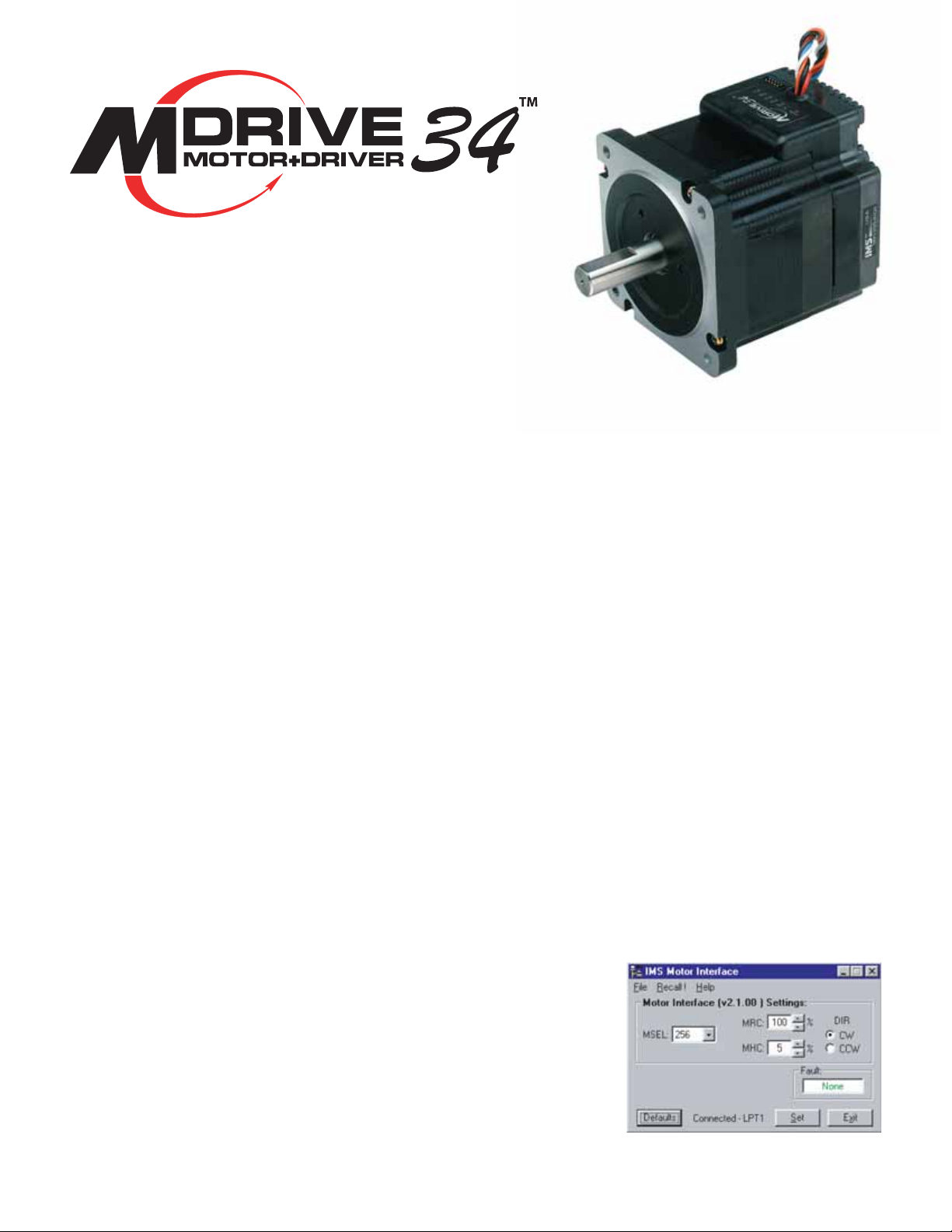
DESCRIPTION
The MDrive NEMA 34 high torque
Integrated Motor and Driver is ide al
for designers who want the sim plic i ty
of a motor with on-board elec tron ics,
but without the expense of an indexer on each axis. The low cost
MDrive34 puts the system de sign er
in the driver’s seat to de cide the best
method of control. The MDrive34’s
integrated elec tron ics eliminate
the need to run the mo tor cabling
through the ma chine, re duc ing the
potential for prob lems due to elec tri cal noise.
The MDrive34 uses a NEMA 34
frame size 1.8° high torque motor com bined with a microstepping driver, and accepts up to 14
res o lu tion set tings from ½ to 256
microsteps per full step. Setup pa ram e ters in clude Microstep Resolution, Motor Run/Hold Current, and
Motor Di rec tion with respect to the
di rec tion in put. These set tings may
be changed on-the-fl y or down load ed
and stored in nonvol a tile mem o ry
with the use of a sim ple GUI which
is provided. This elim i nates the need
for external switch es or re sis tors.
Pa ram e ters are changed via an SPI
port. MDrive34 op er at ing volt age
ranges from +24 to +75 VDC.
The MDrive34 is available in multiple
con fi g u ra tions to fi t various system
needs including a single shaft rotary
motor with optional internal optical
encoder, a dual shaft rotary motor
with control knob, a planetary gearbox, or a long life Acme screw linear
actuator. The rotary MDrive34 is
available in single, double and triple
stack sizes: 24, 31 & 47. In ter face
con nec tions are ac com plished us ing
12.0" (30.5cm) fl ying leads.
The MDrive34 is a compact, pow-
er ful and inexpensive solution that
will reduce system cost, design and
as sem bly time for a large range of
step ping motor applications.
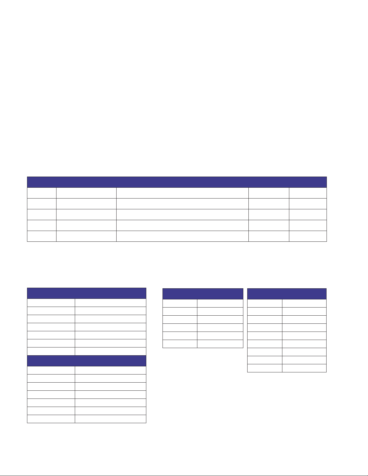
CONFIGURING
The IMS Motor Interface software
is an easy to in stall and use GUI
for con fi g ur ing the MDrive34 from
a computer parallel/SPI port. GUI
access is via the IMS SPI Interface included on the CD shipped
with the product, or download at
www.imshome.com. An optional
cable is avail able for ease of con nect ing and con fi g ur ing the MDrive.
.
The IMS Motor Interface features:
• Easy installation.
• Automatic detection of MDrive
version and communication
confi guration.
• Will not set out-of-range values.
• Tool-tips display valid range
setting for each option.
• Single screen interface
The IMS Motor Interface GUI sim pli fi es MDrive
confi guring with a single screen in ter face.
(below)
.
MDrive34 Microstepping Datasheet REV121704 1
Page 2
MDRIVE34 MICROSTEPPING SPECIFICATIONS
GENERAL SPEC I FI CA TIONS
Input Voltage (+V) Range*.....................................................................................+24 to +75 VDC
Isolated Inputs..................................................................................Step Clock, Direction & Enable
Isolated Input Voltage Range (Sourcing or Sinking) ......................................................+5 to +24 VDC
Step Frequency (Max).........................................................................................................2 MHz
Steps per Revolution ..................................................400, 800, 1000, 1600, 2000, 3200, 5000,
6400, 10000, 12800, 25000, 25600, 50000, 51200
Heat Sink Temperature (Max) ...............................................................................................85° C
Motor Temperature (Max)..................................................................................................100° C
Protection ................................................................................................................Over Voltage
*Power supply current requirements = 4A (maximum) per MDrive34.
Actual power supply current will depend on voltage and load.
PARAMETERS
SETUP PARAMETERS
NAME FUNCTION RANGE UNITS DEFAULT
MHC Motor Hold Current 0 to 100 percent 5
MRC Motor Run Current 1 to 100 percent 25
MSEL Microstep Resolution 2, 4, 5, 8, 10, 16, 25, 32, 50, 64, 125, 128, 250, 256 µsteps per step 256
DIR Motor Direction Override 0 / 1 -- CW
All parameters are set using the supplied IMS Motor Interface GUI and may be changed on-the-fl y.
An optional Parameter Setup Cable is rec om mend ed with fi rst orders.
WIRE/PIN ASSIGNMENTS
CONNECTOR P1 – Flying Leads
WIRE COLOR FUNCTION
White OPTOCOUPLER REFERENCE
Orange STEP CLOCK INPUT
Blue CW/CCW DIRECTION INPUT
Brown ENABLE INPUT
Black POWER GROUND
Red +V (+24 TO +75 VDC)
CONNECTOR P2 (SPI) – 10 Pin Pin-Header
PIN FUNCTION
4 CHIP SELECT
5 GROUND
6 +5 VDC OUTPUT
7 MASTER OUT - SLAVE IN
8 CLOCK
10 MASTER IN - SLAVE OUT
ENCODER WIRE ASSIGNMENTS
ENCODER – Single-End ENCODER – Differential
WIRE COLOR FUNCTION WIRE COLOR FUNCTION
Yellow/Black GROUND Yellow/Black GROUND
Yellow/Violet INDEX Yellow/Violet INDEX +
Yellow/Blue CHANNEL A Yellow/Blue CHANNEL A +
Yellow/Red +5 VDC INPUT Yellow/Red +5 VDC INPUT
Yellow/Brown CHANNEL B Yellow/Brown CHANNEL B +
Yellow/Gray INDEX –
Yellow/Green CHANNEL A –
Yellow/Orange CHANNEL B –
NOTE: For recommended mating connector information, refer to the product's Quick Reference at www.imshome.com/quick.html
MDrive34 Microstepping Datasheet REV121704 2
Page 3

MDRIVE34 MOTOR SPECIFICATIONS
MD3424 Single Stack
Holding Torque .................381.0 oz-in / 269 N-cm
Detent Torque .....................10.9 oz-in / 7.7 N-cm
2
Rotor Inertia ........0.01416 oz-in-sec
/ 1.0 kg-cm
Weight (Motor+Driver)...............67.4 oz / 1909 g
MD3431 Double Stack
Holding Torque .................575.0 oz-in / 406 N-cm
Detent Torque .................14.16 oz-in / 10.0 N-cm
Rotor Inertia ........ 0.02266 oz-in-sec2 / 1.6 kg-cm
Weight (Motor+Driver)................92.1 oz / 2609 g
TORQUE-SPEED CURVES
Rotary Motor
MD3424 Single Stack
24 VDC
45 VDC
75 VDC
24 VDC
45 VDC
75 VDC
282
247
Torque in N - cm
211
170
141
106
71
35
423
353
318
T
orque in N - cm
282
247
211
170
141
106
71
35
847
777
706
635
T
orque in N - cm
465
494
423
353
282
211
140
71
400
350
300
250
200
150
Torque in Oz - In
100
50
0
0 1000 2000 3000 4000 5000 6000 7000
Speed in Full Steps per Second
MD3431 Double Stack
550
500
450
400
350
300
250
200
Torque in Oz - In
150
100
50
0
0 1000 2000 3000 4000 5000 6000 7000
Speed in Full Steps per Second
MD3447 Triple Stack
1200
1100
1000
900
800
700
600
500
400
Torque in Oz - In
300
200
100
0
0 1000 2000 3000 4000 5000 6000 7000
Speed in Full Steps per Second
24 VDC
45 VDC
75 VDC
MD3447 Triple Stack
Holding Torque ...............1061.0 oz-in / 749 N-cm
Detent Torque .................19.83 oz-in / 14.0 N-cm
2
Rotor Inertia ........ 0.04815 oz-in-sec
2
/ 3.4 kg-cm
Weight (Motor+Driver)..............148.5 oz / 4209 g
MD3429 Linear Actuator
Maximum Thrust ....................... 500 lbs / 2224 N
Maximum Screw Defl ection............................. ± 1°
2
Backlash ............................ 0.005 in / 0.127 mm
Weight (without screw)............... 89.0 oz / 2523 g
FORCE-SPEED CURVES
Linear Actuator
24 VDC
500
450
400
350
300
250
200
Force in lbs
150
100
50
0
48 VDC
500
450
400
350
300
250
200
Force in lbs
150
100
50
0
75 VDC
500
450
400
350
300
250
200
Force in lbs
150
100
50
0
0 1000 2000 3000 4000 5000 6000
0 1000 2000 3000 4000 5000 6000
0 1000 2000 3000 4000 5000 6000
Load Limit 500lbs / 2224N
Speed in Full Steps per Second
Load Limit 500lbs / 2224N
Speed in Full Steps per Second
Load Limit 500lbs / 2224N
Speed in Full Steps per Second
Scre
Scre
Scre
Scre
Scre
Scre
Scre
Scre
Scre
Scre
Scre
Scre
w EScre
w D
w C
w B
w A
w EScre
w D
w C
w B
w A
w EScre
w D
w C
w B
w A
7000
7000
7000
2224
2002
1779
1557
1334
1112
890
667
445
222
2224
2002
1779
1557
1334
1112
890
667
445
222
2224
2002
1779
1557
1334
1112
890
667
445
222
2
Force in N
Force in N
Force in N
MDrive34 Microstepping Datasheet REV121704 3
Page 4

MDRIVE34 WITH PLANETARY GEARBOX
The MDrive34 is available with a Planetary Gearbox
option developed to increase torque at lower speeds,
enable better inertia matching and produce fi ner
positional resolutions. These effi cient, low maintenance Planetary Gearbox come fully assembled with
the MDrive and are offered in a large number of
reduction ratios in 1-, 2- and 3-stage confi gurations.
An optional NEMA Flange allows mounting the Planetary Gearbox to the load using a standard NEMA
bolt circle. Planetary Gearbox may be combined with
other MDrive34 options, however are unavailable on
Linear Actuator versions.
Parameters 1-Stage 2-Stage 3-Stage
Permitted Output Torque (oz-in/Nm)....................... 2832/20.0........8496/60.0.......16992/120.0
Gearbox Effi ciency..................................................... 0.80.................. 0.75...................0.70
Maximum Backlash (degree)....................................... 1.0° ...................1.5° ................... 2.0°
Ouput Side With Ball Bearing
Maximum Load, Radial (lb-force/N).......................... 90/400 ............135/600 .......... 225/1000
Maximum Load, Axial (lb-force/N)............................. 18/80 ..............27/120 ............. 45/200
Weight - Gearbox Only (oz/g).................................64.4/1827........ 89.5/2538........114.6/3248
Weight - Gearbox & NEMA Flange (oz/g) ................66.7/1890........ 92.6/2625........118.5/3360
PLANETARY GEARBOX MECHANICAL SPECIFICATIONS
Dimensions in Inches (mm)
Planetary Gearbox for MDrive34
M6 x 0.472 (12.0) DeepM6 x 0.472 (12.0) Deep
3.386 SQ.
(86.0 SQ.)
1.929
(49.0)
Ø 1.969 +0.0006/-0.0004
(Ø 50.0 +0.015/-0.010)
Ø 0.748 +0/-0.0008
(Ø 19.0 +0/-0.021)
1.575
(40.0)
0.197
(5.0)
k1 ±0.02 (±0.5)
Ø 3.189
(Ø 81.0)
Gearbox Ratios (Rounded)
1-Stage 2-Stage 3-Stage
3.70:1 13.73:1 50.89:1
5.18:1 15.88:1 58.85:1
6.75:1 18.36:1 68.06:1
19.20:1 71.16:1
22.20:1 78.71:1
25.01:1 92.70:1
26.85:1 95.17:1
28.93:1 99.50:1
34.97:1 107.20:1
45.56:1 115.07:1
MDRIVE34
123.97:1
129.62:1
139.13:1
149.90:1
168.84:1
181.24:1
195.26:1
236.09:1
307.54:1
Ø 2.56
(Ø 65.0)
Ctrg. DIN 332-D M6x16
Key DIN 6885-A-6x6x28mm
Planetary Gearbox with Optional NEMA Output Flange
1.811
4x Ø 0.217 (Ø 5.5) Hole
2.739
(69.58)
2.739
(69.58)
3.386 SQ.
(86.0 SQ.)
Ø 2.874 +0/-0.0012
(Ø 73.0 +0/-0.030)
Ø 0.748 +0/-0.0008
(Ø 19.0 +0/-0.021)
Ctrg. DIN 332-D M6x16
Key DIN 6885-A-6x6x28mm
(46.0)
1.575
(40.0)
0.079
(2.0)
0.394
(10.0)
k1 Gearbox
k2 Gearbox w/
NEMA Flange
k2 ±0.02 (±0.5)
Ø 3.189
(Ø 81.0)
MDrive34 Microstepping Datasheet REV121704 4
Gearbox Lengths
1-Stage 2-Stage 3-Stage
4.315
(109.6)
4.433
(112.6)
MDRIVE34
5.169
(131.3)
5.287
(134.3)
Inches (mm)
6.024
(153.0)
6.142
(156.0)
Page 5

MDRIVE34 MICROSTEPPING – MECHANICAL SPECIFICATIONS
Dimensions in Inches (mm)
Rotary MDrive34: Single Shaft, Control Knob & Encoder Versions
12.0" (30.5 cm)
Flying Leads
0.08 (2.0)
3.73
(94.7)
4X Ø 0.22 (Ø 5.5)
1.46 ±0.04
(37.0 ±1.0)
0.984 ±0.01
(25.0 ±0.25)
0.512 ±0.004
(13.0 ±0.1)
Ø 0.5512 +0/-0.0005
(Ø 14.0 +0/-0.013)
2.33
(59.2)
2.07
(52.6)
MDrive Lengths
Stack Size
3424 3.81 (96.8) 4.97 (126.2)
3431 4.60 (116.8) 5.76 (146.3)
3447 6.17 (156.7) 7.34 (186.4)
L
–
MAX2
Control Knob
Inches (mm)
L
MAX
SINGLE SHAFT or
ENCODER VERSION
Ø 1.90
(Ø 48.3)
L
MAX
L
MAX2
CONTROL KNOB VERSION
Linear Actuator MDrive34
12.0" (30.5 cm)
Flying Leads
L
0.06
(1.5)
0.39
(10.0)
MAX2
Ø 2.874 ±0.002
(Ø 73.0 ±0.05)
4X Ø 0.26
(Ø 6.6)
Ø 2.875 +0/-0.002
(Ø 73.03 +0/-0.05)
2.739 ±0.01 SQ.
(69.58 ±0.25 SQ.)
3.40 SQ.
(86.4 SQ.)
MDrive34 Top View
P1P2
Flying Leads
10 Pin Connector
2.33
(59.2)
3.73
(94.7)
0.625
(15.88)
2.07
(52.6)
4.46
(113.3)
6.00
(152.4)
0.39
(10.0)
0.1
(2.5)
Ø 0.30
(Ø 7.6)
0.71
(18.0)
7/16-14
UNC-2A THREAD
2.730 ±0.008 SQ.
(69.34 ±0.2 SQ.)
3.40 SQ.
(86.4 SQ.)
MDrive34 Microstepping Datasheet REV121704 5
Page 6

MDRIVE34 MICROSTEPPING – OPTIONS
Control Knob
The MDrive34 is available with a fac to ry-mount ed rear
control knob for man u al shaft positioning.
Screw A .............0.005”/full step
Screw B .............0.0025”/full step
Screw C ............. 0.00125”/full step
Screw D ............. 0.000625”/full step
Planetary Gearbox
Effi cient, low maintenance Planetary Gearbox are of-
fered assembled with the MDrive34. Details inside.
Encoder
The MDrive34 is available with a factory-mount ed in-
ternal op ti cal en cod er. Available line counts are 100,
200, 250, 400, 500 or 1000. All en cod ers, except
the 1000 line, have an in dex mark. Encoders are available in both single-end and dif fer en tial confi gurations.
Linear Actuator
The MDrive34 with long life Acme Screw Linear Actua-
tor is avail able with the following trav el/full step:
Screw E ............. 0.0005"/full step
Standard screw length is 6.0” (152.4mm) plus the
mounting end thread. Cus tom lengths up to 24.0”
are available without mounting end thread.
Linear Actuators are Non-Captive style. Contact the
factory regarding Captive Shaft or External styles.
Parameter Setup Cable
A low cost ac ces so ry which eliminates the need for
users to wire com mu ni ca tions. This 6' (1.8m) cable
includes built-in logic level shifting circuitry to ac com mo date the 3.3v por ts on some PCs and plugs in
easily to con nect a stan dard DB-25 PC par al lel/SPI
port to the MDrive's 10 pin pin-header (P2). Order
Cable Part No. MD-CC100-000.
ORDER INFORMATION
MDRIVE34 MICROSTEPPING OPTIONS
Control
Knob
Stack Sizes
24 = Single Stack
29 = Linear Actuator
31 = Double Stack
47 = Triple Stack
MDMF 34
Example #1: Part Number MDMF3431 is an MDrive34
Microstepping with Flying Leads, NEMA 34 motor, stack size 31.
†
Stack Size 29 is only available as a Linear Actuator and is the ONLY size Linear Actuator offered. (MDMF3429LX)
†
OPTION
Planetary
Gearbox
Internal
Encoder
Linear
Actuator
Screw Type (Travel/Full Step)
A = 0.005”
B = 0.0025”
C = 0.00125”
D = 0.000625”
E = 0.0005”
N
G
Gearbox Ratio
Rounded to Nearest Whole Number
E
S = Single End
D = Differential
†
L
Line Count
100, 200, 250, 400, 500, 1000
Custom Screw Length
Range 2.0” to 24.0”
Format XX.X
eg. 08.5 for an 8.5” Screw
(6.0” Screw Length Standard)
Example #2: MDMF3431N
Adds a Control Knob
to the part shown in example #1.
Example #3: MDMF3431G5
Rounding ratio to the nearest whole number,
the above adds a Planetary Gearbox with
5.18:1 ratio to the part shown in example #1.
Add -F if optional NEMA Flange is desired.
Example #4: MDMF3431ED500
Adds a 500 line count internal Differential
Encoder to the part shown in example #1.
Example #5: MDMF3429LA10.5
MDrive34 Microstepping Linear Actuator
with a 0.005”/Full Step Acme
Screw custom cut to 10.5”.
MAY NOT be combined with other options.
Note: MDrive34 Linear Actuator
Available ONLY in Stack Size 29
P.O. Box 457, 370 N. Main Street
Marlborough, CT 06447 U.S.A.
Phone: 860/295-6102
Fax: 860/295-6107
E-mail: info@imshome.com
Home Page: www.imshome.com
Distributed By:
TECHNICAL SUPPORT
Eastern U.S.
Phone: 860/295-6102
Fax: 860/295-6107
E-mail: etech@imshome.com
Western U.S.
Phone: 760/966-3162
Fax: 760/966-3165
E-mail: wtech@imshome.com
IMS MOTORS DIVISION
105 Copperwood Way, Suite H
Oceanside, CA 92054
Phone: 760/966-3162
Fax: 760/966-3165
E-mail: motors@imshome.com
Product information covered by IMS Product Disclaimer available at www.imshome.com.
Visit the IMS web site for the most up-to-date product information.
© 2002, 2004 Intelligent Motion Systems, Inc. All Rights Reserved. REV121704
IMS EUROPE
Hahnstrasse 10, VS-Schwenningen
Germany D-78054
Phone: +49/7720/94138-0
Fax: +49/7720/94138-2
E-mail: info@imseuropehome.com
European Sales Management
4 Quai Des Etroits
69005 Lyon, France
Phone: +33/4 7256 5113
Fax: +33/4 7838 1537
E-mail: bmartinez@imshome.com
German Sales/Technical Support
Phone: +49/35205/4587-8
Fax: +49/35205/4587-9
E-mail: hruhland@imshome.com
GmbH
 Loading...