

Page 1
Quick Reference
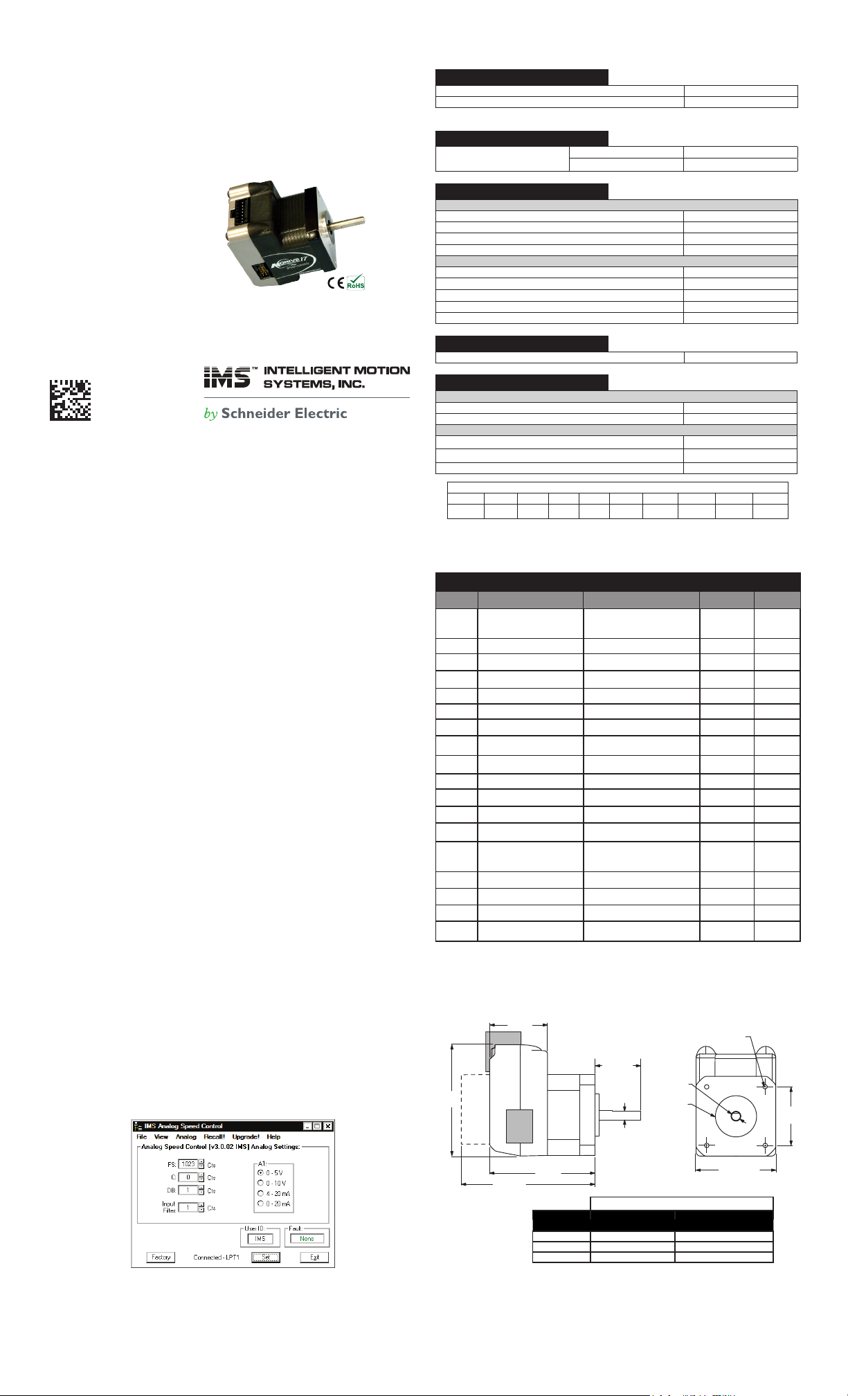
Dimensions in inches (mm)
Motor Length LMAX1 (Single Shaft
or Internal Encoder)
LMAX2 (Control Knob
or External Encoder)
Single 2.20 (55.9) 2.79 (70.9)
Double 2.43 (61.7) 3.02 (76.7)
Triple 2.77 (70.4) 3.37 (85.6)
P1
Connector
Option
2.30
(58.3)
P2
1.19
(30.2)
L
MAX2
L
MAX
0.177
(4.49 )
0.94
(23.9)
Connector
Option
Ø 0.866
(Ø 21.996)
Ø 0.1968
(Ø 4.999)
1.68 SQ.
(42.7 SQ.)
1.220 SQ.
(31.0 SQ.)
4X M3x0.5 THREAD
x0.15 MIN DEEP
MDrive17Plus
Speed Control
Notes and Warnings
Installation, configuration and maintenance must be carried out by qualified
technicians only. You must have detailed information to be able to carry out this
work. This information can be found in the user manuals.
• Unexpected dangers may be encountered when working with this product!
• Incorrect use may destroy this product and connected components!
The user manuals are not included. You can obtain them from the Internet at:
http://www.imshome.com/mdrive17plus_mdo.html.
Required for Setup*
PC running Microsoft•
IMS SPI Motor Interface (available online)•
+12 to +48 VDC unregulated linear or switching power supply. (Recom-•
mended: IMS IP404 or ISP200-4)
10 kΩ Potentiometer for velocity control (or appropriate current source if •
using current mode)
Two (2) SPST switches or controller I/O points to control axis direction •
and the on/off state of the internal clock generator.
SPI communications interface (Recommended: IMS MD-CC300-001 or •
MD-CC302-001 Communication Converters)
Depending on your MDrivePlus connectors configuration, you may also need:
If using a 7-pin pluggable terminal IMS recommends 22 AWG shielded •
twisted pairs for logic wiring. Wire guage for for power connection varies
with the distance from the MDrive and current. See MDrivePlus product
manual.
* If you purchased your MDrivePlus with a QuickStart Kit, you have received all
of the connecting cables needed for initial functional setup and system testing.
Getting Started
All documentation, software and resources are available online at:
http://www.imshome.com/mdrive17plus_mdo.html
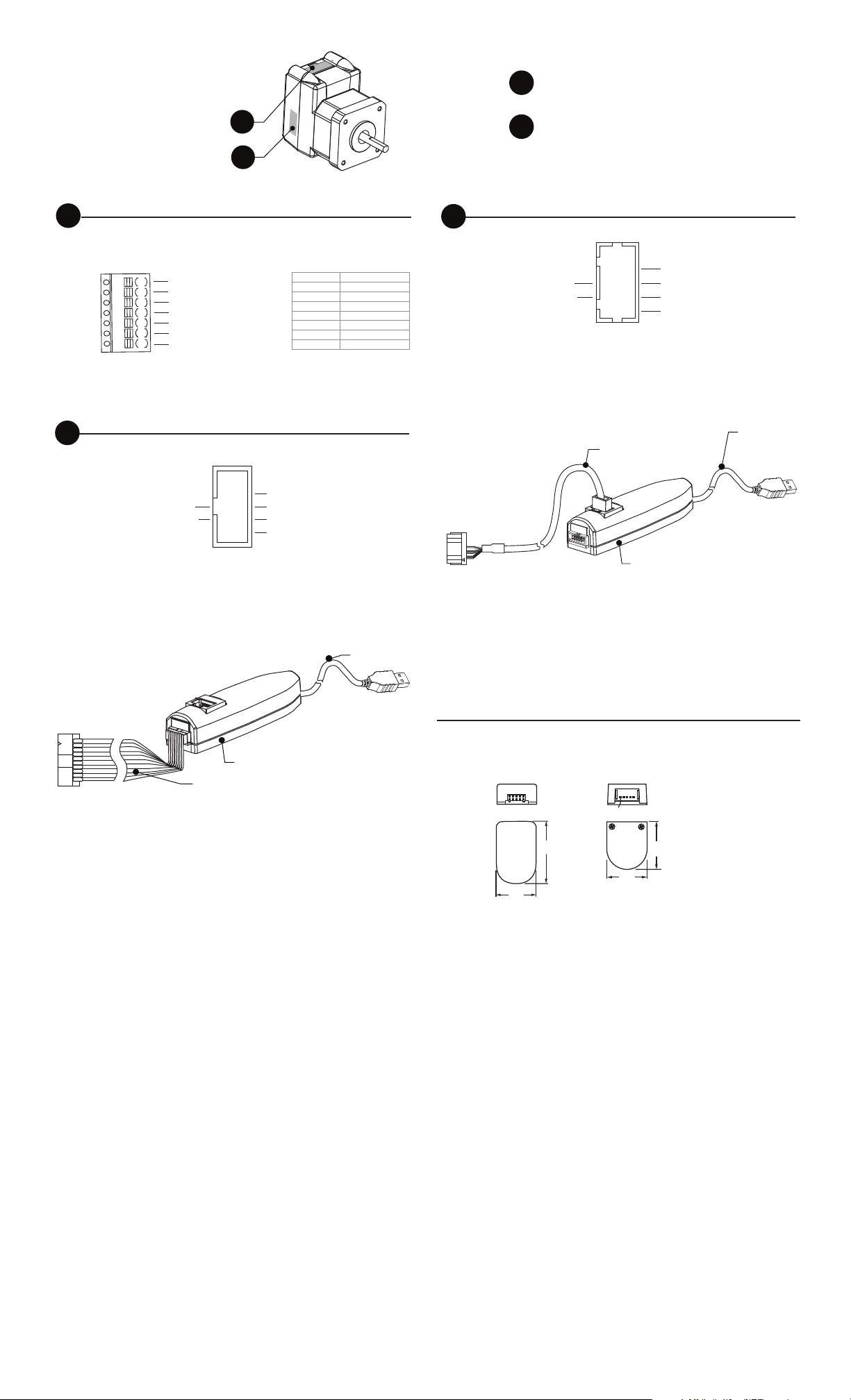
Connecting Power and I/O
Your MDrivePlus is configured with power and I/O combined on a single connector. Please refer to the opposite side of this document for connecting details
and available IMS connectivity options including Prototype Development Cables
and Mating Connector Kits.
Connecting Communications
Connect IMS USB to SPI communications converter to MDrivePlus and 1.
PC.
Install the communication converter drivers onto PC (available online).2.
Install and open SPI Motor lnterface.3.
Apply power to MDrivePlus.4.
Parameters may be adjusted via two screens, the Motor Settings screen 5.
or the I/O settings screen (shown below), accesible via the View menu.
®
Windows XP Service Pack 2 or greater.
MDrive17Plus Speed Control Specifications
Electrical Specifications
Input Voltage (+V) Range* +12 to +48 VDC
Max Power Supply Current (Per MDrive17Plus)* 2 A
*Actual Power Supply Current will depend on Voltage and Load.
Environmental Specifications
Operating Temperature
(non-condensing)
Input Specifications
Analog Input
A/D Resolution 10 Bit
Range (Voltage Mode) 0 to +5VDC, 0 to +10 VDC
Range (Current Mode) 0 to 20 mA, 4 to 20 mA
Range (PWM) 15 to 20 kHz
Stop/Start and Direction
Range TTL
Logic Threshold (Logic 0) < 0.8 VDC
Logic Threshold (Logic 1) > 2.2 VDC
Internal Pull-Up Resistance 20 kΩ
Protection Transient
Communications Specifications
Protocol SPI
Motion Specifications
Velocity
Oscillator Frequency (Max.) 5 MHz
Resolution 0.5961 Steps/Second
Acceleration/Deceleration
Range 1.5 x 10⁹ Steps/Second
Resolution 90.9 Steps/Second
Number of Microstep Resolution Settings 20
200 400 800 1000 1600 2000 3200 5000 6400 10000
12800 20000 25000 25600 40000 50000 51200 36000
1=0.01 deg/µstep 2=1 arc minute/µstep 3=0.001 mm/µstep
Heat Sink -40°C to +85°C
Motor -40°C to +100°C
Available Microsteps Per Revolution
1
21600225400
Setup Parameters
MDrivePlus Speed Control Setup Parameters
Name Function Range Units Default
A1 Analog Input Mode
ACCL Acceleration 91 to 1.5 X 10
C Joystick Center 0 to 1022 counts 0
DB Deadband 0 to 255 counts 1
DECL Deceleration 91 to 1.5 X 10
DIR Motor Direction Override Clockwise/Counterclockwise – CW
FAULT Fault/Checksum Error Error Code — None
FS Full Scale
HCDT Hold Current Delay Time HCDT + MSDT <= 65535 milliseconds 500
IF Analog Input Filter 1 to 1000 counts 1
MHC Motor Hold Current 0 to 100 percent 5
MRC Motor Run Current 1 to 100 percent 25
MSDT Motor Settling Delay Time MSDT + HCDT <= 65535 milliseconds 0
MSEL Microstep Resolution
SSD Stop/Start Debounce 0 to 255 milliseconds 0
VI Initial Velocity 0 to < VM steps/sec 1000
VM Maximum Velocity VI to 5,000,000 steps/sec 768000
USER ID User ID Customizable
0 to +5 VDC, 0 to +10 VDC,
4 to 20 mA, 0 to 20 mA, 15 to
25kHz PWM
1 to 1023 (205 to 1023 – 4 to
20 mA mode)
1, 2, 4, 5, 8, 10, 16, 25,
32, 50, 64, 100,108, 125,
127,128, 180, 200, 250, 256
9
9
0 to +5
—
steps/sec21,000,000
steps/sec21,000,000
counts 1023
µsteps per
full step
1-3
characters
VDC
Note: Parameter settings may be changed on-the-fly.
Mechanical Specifications
2
2
3
256
IMS
All documentation, software, program examples and resources are available
online at: http://www.imshome.com/mdrive17plus_mdo.html
MDrive17Plus Speed Control Quick Reference R020708
Page 2
P1
P2
P2
P1
MDrive17Plus
P2
P2
P1
User Supplied Recommended
Wire: 22 AWG Stranded
Stop/Start
CW/CCW Direction
+5 VDC Output
Speed Control
Logic Ground
GND
+V
Pluggable Terminal Flying Lead Colors
1
3
5
7
2
4
6
MISO
+5 VDC Out*
Chip Select
MOSI
SPI Clock
GND
1
3
5
7
9
2
4
6
8
10
pins not labeled are no connect.
*used to power the MD-CC300-001 only.
To computer
USB port
To MDrivePlus 10-pin
IDC connector
6.0’ (1.8m)
in-line converter
6.0’ (1.8m)
Single-End OpticalDifferential Optical
(Pin 1) Brown: Ground
Violet: IDX
Blue: CH A
Orange: +5 VDC In
Yellow: CH B
Orange/White: +5 VDC In
White/Orange: Ground
White/Blue: CH ABlue/White: CH A+
White/Green: CH BGreen/White: CH B+
White/Brown: IDXBrown/White: IDX+
p/n: ED-CABLE-6
6.0’ (1.8 m)
p/n: ES-CABLE-2
12” (30.4 cm)
Optional Encoder Cables
wire color: function wire color: function
2.04
(51.8)
.
1.22
(31.0)
.
Pin 1
1.20
(30.4)
1.42
(36.1)
.
.
MISO
GND
SPI Clock
+5 VDC Out*
MOSI
Chip Select
9
7
5
3
1
10
8
6
4
2
pins not labeled are no connect.
*used to power the MD-CC302-001 only.
To computer
USB port
To MDrivePlus
10-pin friction lock
wire crimp connector
6.0’ (1.8m)
in-line converter
6.0’ (1.8m)
Speed Control
Connectivity Options
Connector Style Function
Pluggable Terminal......................
I/O and Power
Flying Leads................................ I/O and Power
I/O & Power
Pluggable terminal or flying leads
Communications
10-pin IDC
Wire Color Function
Violet Stop/Start
Blue CW/CCW Direction
Green Speed Control
Yellow +5 VDC Output
Gray Logic Ground
Black Ground
Red +V
10-pin IDC................................... Communications
10-pin Wire Crimp.......................
Communications
Communications
10-pin Wire Crimp
Communications Converter p/n: MD-CC302-001
Electrically isolated in-line USB to SPI converter pre-wired with mating connector
to conveniently program and set configuration parameters.
Communications Converter p/n: MD-CC300-001
Electrically isolated in-line USB to SPI converter pre-wired with mating connector
to conveniently program and set configuration parameters.
Mating Connector Kit p/n: CK-01
Use to make your own cables, kit contains 5 mating connector shells for making
interface cables.
IDC Parts Shell: SAMTEC TCSD-05-01-N
Ribbon Cable: AMP 1-57051-9
Mating Connector Kit p/n: CK-02
Use to make your own cables, kit contains 5 mating connector shells for making
interface cables.
Hirose Parts Shell: DF11-10DS-2C
Pins: DF11-2428SC
Crimp Tool: DF11-TA2428HC
Encoder Options
External Optical (Differential or Single-End)
Copyright © Intelligent Motion Systems, Inc. www.imshome.com
 Loading...