

Page 1

T
TM
intelligent motion systems, inc.
Excellence in Motion
TM
OPERATING INSTRUCTIONS
Page 2

The information in this book has been carefully checked and is believed to be accurate; however, no
responsibility is assumed for inaccuracies.
Intelligent Motion Systems, Inc., reserves the right to make changes without further notice to any products
herein to improve reliability, function or design. Intelligent Motion Systems, Inc., does not assume any liability
arising out of the application or use of any product or circuit described herein; neither does it convey any
license under its patent rights of others. Intelligent Motion Systems and are trademarks of Intelligent
TM
Motion Systems, Inc.
Intelligent Motion Systems, Inc.’s general policy does not recommend the use of its products in life support or
aircraft applications wherein a failure or malfunction of the product may directly threaten life or injury. Per
Intelligent Motion Systems, Inc.’s terms and conditions of sales, the user of Intelligent Motion Systems, Inc.,
products in life support or aircraft applications assumes all risks of such use and indemnifies Intelligent Motion
Systems, Inc., against all damages.
© 2002 Intelligent Motion Systems, Inc.
All Rights Reserved
Page 3

Table of Contents
Part 1: General Information And Hardware Information
Section 1.1: Introduction to the MDrive17 Motion Control ....................................................................................................................... 5
Introduction to the MDrive17 Motion Control ................................................................................................................................................................................5
Feature Summary .........................................................................................................................................................................................................................5
Section 1.2: MDrive17 Motion Control Specifications ............................................................................................................................... 6
Section Overview .........................................................................................................................................................................................................................6
Rotary Motor Specifications ......................................................................................................................................................................................................... 6
Mechanical Specifications - Dimensions in Inches (mm) ...................................................................................................................................................6
MDrive Motion Control 1713 Motor Specs and Speed/T orque Curves................................................................................................................................ 6
MDrive Motion Control 1715 Motor Specs and Speed/T orque Curves................................................................................................................................ 7
MDrive Motion Control 1719 Motor Specs and Speed/T orque Curves................................................................................................................................ 7
Linear Motor Specifications ..........................................................................................................................................................................................................7
Mechanical Specifications - Dimensions in Inches (mm) ...................................................................................................................................................7
Speed-Force Curve: 24 VDC ..............................................................................................................................................................................................8
Linear Actuator MDrive Motion Control 1713 Specs and Speed-Force Curves ..................................................................................................................8
Speed-Force Curve: 45 VDC ..............................................................................................................................................................................................8
MDrive17 Motion Control ACME Screw ...............................................................................................................................................................................9
General Specifications..................................................................................................................................................................................................................9
General Specifications................................................................................................................................................................................................................ 10
Power Supply Requirements ......................................................................................................................................................................................................10
Recommended IMS Power Supplies.................................................................................................................................................................................. 10
Thermal Specifications ...............................................................................................................................................................................................................10
Section 1.3: Introduction to the MDrive23 Motion Control ..................................................................................................................... 11
Introduction to the MDrive23 Motion Control .............................................................................................................................................................................. 11
Feature Summary ....................................................................................................................................................................................................................... 11
Section 1.4: MDrive23 Motion Control Specifications ............................................................................................................................. 12
Section Overview .......................................................................................................................................................................................................................12
Rotary Motor Specifications ....................................................................................................................................................................................................... 12
Mechanical Specifications - Dimensions in Inches (mm) .................................................................................................................................................12
MDrive Motion Control 2218 Motor Specs and Speed/T orque Curves.............................................................................................................................. 12
MDrive Motion Control 2222 Motor Specs and Speed/T orque Curves.............................................................................................................................. 13
MDrive Motion Control 2231 Motor Specs and Speed/T orque Curves.............................................................................................................................. 13
Linear Motor Specifications ........................................................................................................................................................................................................13
Mechanical Specifications - Dimensions in Inches (mm) .................................................................................................................................................13
Speed-Force Curve: 24 VDC ............................................................................................................................................................................................ 14
Linear Actuator MDrive Motion Control 2218 Specs and Speed-Force Curves ................................................................................................................14
Speed-Force Curve: 45 VDC ............................................................................................................................................................................................ 14
MDrive23 Motion Control ACME Screw .............................................................................................................................................................................15
General Specifications................................................................................................................................................................................................................15
General Specifications................................................................................................................................................................................................................16
Power Supply Requirements ......................................................................................................................................................................................................16
Recommended IMS Power Supplies.................................................................................................................................................................................. 16
Thermal Specifications ...............................................................................................................................................................................................................16
Part 2: Connecting, Configuring And Programming The MDrive Motion Control
Section 2.1: Interfacing the MDrive Motion Control ................................................................................................................................. 19
Section Overview .......................................................................................................................................................................................................................19
Layout and Interface Guidelines ................................................................................................................................................................................................19
Recommended Wiring ............................................................................................................. ..........................................................................................19
Pin Configuration and Descriptions ............................................................................................................................................................................................ 19
Interfacing Power........................................................................................................................................................................................................................ 20
Interfacing RS-485 Communications .........................................................................................................................................................................................20
Single MDrive ....................................................................................................................................................................................................................20
Multiple MDrive Motion Control System (Party Mode) ......................................................................................................................................................21
Interfacing the Digital I/O ...........................................................................................................................................................................................................22
Uses of the Digital I/O ......................................................................................................................................................................................................22
Interfacing Inputs .............................................................................................................................................................................................................. 22
Interfacing Outputs ...........................................................................................................................................................................................................24
Interfacing the Analog Input .......................................................................................................................................................................................................25
Sample Usage ................................................................................................................................................................................................................... 25
Section 2.2: MDrive Motion Control Software Introduction ................................................................................................................... 26
Section Overview .......................................................................................................................................................................................................................26
Installing and Using IMS T erminal...............................................................................................................................................................................................26
System Requirements ......................................................................................................................................................................................................26
Installation .........................................................................................................................................................................................................................26
Using the IMS Terminal Software ......................................................................................................................................................................................27
Setting the Programmable Function Keys ........................................................................................................................................................................28
Upgrading the MDrive Motion Control Firmware......................................................................................................................................................................... 28
MDrive Motion Control Programming.......................................................................................................................................................................................... 29
Operational Modes .............................................................................................................................................................................................................29
Basic Components of MDrive Motion Control Software ............................................................................................................................................................29
Instructions........................................................................................................................................................................................................................ 29
Variables ............................................................................................................................................................................................................................29
Flags.................................................................................................................................................................................................................................. 30
Keywords ...........................................................................................................................................................................................................................30
Most Commonly Used Variables and Commands ...................................................................................................................................................................... 30
1
Page 4

Variables ............................................................................................................................................................................................................................30
Math Functions ..................................................................................................................................................................................................................31
Motion Commands.............................................................................................................................................................................................................31
I/O Commands ..................................................................................................................................................................................................................32
System Instructions .......................................................................................................................................................................................................... 32
Program Instructions ......................................................................................................................................................................................................... 32
Section 2.3: MDrive Motion Control Command Set Summary ............................................................................................................... 35
Setup Instructions, Variables and Flags .....................................................................................................................................................................................35
Miscellaneous Instructions, Variables and Flags ........................................................................................................................................................................35
Motion Instructions, Variables and Flags.................................................................................................................................................................................... 35
I/O Instructions, Variables and Flags ......................................................................................................................................................................................... 36
Program Instructions, Variables and Flags.................................................................................................................................................................................36
Position Related Instructions, Variables and Flags ....................................................................................................................................................................37
Encoder Related Instructions, Variables and Flags....................................................................................................................................................................37
Mathematical Functions.............................................................................................................................................................................................................. 37
Section 2.4: MDrive Motion Control Command Set .................................................................................................................................. 38
Appendix A: ASCII TABLE ................................................................................................................................................................................64
Appendix B: Error Codes ................................................................................................................................................................................. 65
List of Figures
Figure 1.1 Rotary MDrive17 Motion Control Mechanical Specifications ..................................................................................................................................6
Figure 1.2 Rotary MDrive17 Motion Control 1713 Speed/Torque Data.....................................................................................................................................6
Figure 1.3 Rotary MDrive17 Motion Control 1715 Speed/Torque Data.....................................................................................................................................7
Figure 1.4 Rotary MDrive17 Motion Control 1719 Speed/Torque Data.....................................................................................................................................7
Figure 1.5 Linear Actuator MDrive17 Motion Control Mechanical Specifications .....................................................................................................................7
Figure 1.6 Speed-Force Curve - 24VDC (100% Current) .........................................................................................................................................................8
Figure 1.7 Speed-Force Curve - 45VDC (100% Current) .........................................................................................................................................................8
Figure 1.8 Rotary MDrive23 Motion Control Mechanical Specifications ................................................................................................................................12
Figure 1.9 Rotary MDrive23 Motion Control 2218 Speed/Torque Data...................................................................................................................................12
Figure 1.10 Rotary MDrive23 Motion Control 2222 Speed/Torque Data................................................................................................................................... 13
Figure 1.11 Rotary MDrive23 Motion Control 2231 Speed/Torque Data................................................................................................................................... 13
Figure 1.12 Linear Actuator MDrive23 Motion Control Mechanical Specifications ...................................................................................................................13
Figure 1.13 Speed-Force Curve - 24VDC (100% Current) .......................................................................................................................................................14
Figure 1.14 Speed-Force Curve - 45VDC (100% Current) .......................................................................................................................................................14
Figure 2.1 Power Supply Interface .........................................................................................................................................................................................20
Figure 2.2 RS-485 Interface, Single MDrive Motion Control ..................................................................................................................................................20
Figure 2.3 RS-485 Interface, Multiple MDrive Motion Control System ..................................................................................................................................21
Figure 2.4 Input Interfaced to a Switch ..................................................................................................................................................................................22
Figure 2.5 Input Interfaced to a PLC ...................................................................................................................................................................................... 22
Figure 2.6 TTL Interface to an Input Group ............................................................................................................................................................................23
Figure 2.7 Output Interfaced to an LED ................................................................................................................................................................................. 24
Figure 2.8 Output Interfaced to a Relay ................................................................................................................................................................................ 24
Figure 2.9 Outputs Interfaced tp LED’s as a Group............................................................................................................................................................... 24
Figure 2.10 Analog Input Interface ...........................................................................................................................................................................................25
Figure 2.11 IMS Terminal Window ............................................................................................................................................................................................. 26
Figure 2.12 IMS Terminal Preferences......................................................................................................................................................................................27
Figure 2.13 IMS Terminal Upgrader Window ............................................................................................................................................................................. 28
List of T ables
T able 1.1 Rotary MDI1713 Motor Specifications .....................................................................................................................................................................6
T able 1.2 Rotary MDI1715 Motor Specifications .....................................................................................................................................................................7
T able 1.3 Rotary MDI1719 Motor Specifications .....................................................................................................................................................................7
Table 1.4 Linear Actuator MDrive17 Motion Control Motor Specifications ..............................................................................................................................8
Table 1.5 ACME Screws for Linear Actuator MDrive17 Motion Control ..................................................................................................................................9
T able 1.6 Rotary MDI2218 Motor Specifications ...................................................................................................................................................................12
T able 1.7 Rotary MDI2222 Motor Specifications ...................................................................................................................................................................13
T able 1.8 Rotary MDI2231 Motor Specifications ...................................................................................................................................................................13
Table 1.9 Linear Actuator MDrive23 Motion Control Motor Specifications ............................................................................................................................14
Table 1.10 ACME Screws for Linear Actuator MDrive23 Motion Control ................................................................................................................................15
T able 2.1 P1 Pin Configuration and Description .................................................................................................................................................................... 19
T able 2.2 P2 Pin Configuration and Description .................................................................................................................................................................... 20
T able 2.3 Input Functions ......................................................................................................................................................................................................22
T able 2.4 I/O Group Truth Table.............................................................................................................................................................................................23
T able 2.5 Output Functions ...................................................................................................................................................................................................24
T able 2.6 Microstep Resolution Settings ...............................................................................................................................................................................51
2
Page 5

Part 1: General Information
and Hardware Specifications
3
Page 6

Intentionally Left Blank
4
Page 7

Section 1.1
Introduction to the MDrive17 Motion Control
Introduction to the MDrive17 Motion Control
The MDrive17 Motion Control offers the system designer a low-cost, intelligent motion controller integrated with a NEMA 17 high
torque stepping motor and a +12 to +48 VDC microstepping drive.
The MDrive17 Motion Control adds a versatile array of functions by combining a complete programmable motion controller with
our already compact and cost effective standard MDrive17, adding little cost and no increase in size. Standard offerings include four
5 to 24 volt programmable I/O points, one 10-bit 0 to 5 volt analog input, 0 to 5 MHz step clock rate, microstep resolution up to
51,200 steps per revolution and a full featured easy-to-program instruction set.
The MDrive17 Motion Control communicates using the RS-485 communications protocol, this allows for point-to-point or multi-
drop communications using one communications port. Addressing and hardware support up to 62 MDrive nodes in a system. The
communications BAUD rate is software selectable and ranges from 4.8 kbps to 115 kbps.
The MDrive17 is also available with an optional closed loop control. The closed loop configuration adds a 512 line (2048 count)
internal magnetic rotary encoder with index mark without increasing the length of the unit. Closed loop configuration adds position
maintenance, stall detection and find index mark.
A vailable motor configurations include: single shaft, double shaft with control knob, and long life ACME screw linear actuator .
Rotary versions are available in three stack lengths: 13, 15 & 19. Interface connections are accomplished using either a 7 position
terminal block or optional 12” flying leads.
Feature Summary
! Integrated Microstepping Drive/Motion Controller with Optional Encoder/NEMA 17 High Torque Stepping Motor
! +12 to +48VDC Input Voltage
! Low Cost
! Extremely Compact
! Available Configurations: Single Shaft*, Linear Actuator, Integral Encoder*, Double Shaft with Knob for Manual
! Three Motor Stack Lengths Available*
! Single Power Supply
! Microstep Resolution up to 51,200 Steps Per Revolution
! Open Loop or Optional Closed Loop Control
! Programmable Motor Run and Hold Current Settings
! Four 5 to 24 VDC Programmable I/O Points
! One Analog 10 Bit, 0 to 5 Volt Analog Input
! 0 to 5 MHz Step Clock Rate, SelecTable 1. in 0.59 Hz Increments
! RS-485 Communications Protocol
! Communications BAUD Rate SelecTable 1. from 4.8 kbps to 115 kbps
! 62 Software Addresses for Multidrop Communications
! Simple 1 and 2 Character Programming Instructions
! Pluggable Terminal Strip or 12” Flying Lead Interface
! Optional Integrated RS-232 to RS-485 Converter/Communications Cable
*Rotary Motor Only
Positioning*
5
Page 8
Section 1.2
MDrive17 Motion Control Specifications
Section Overview
This section contains mechanical, motor and electrical specifications specific to each version of the MDrive17 Motion Control.
Shown are:
!
! Linear Motor Specifications
! General Specifications
! Power Supply Requirements
! Thermal Specifications
Rotary Motor Specifications
Mechanical Specifications - Dimensions in Inches (mm)
Rotary Motor Specifications
Standard Rotary Motor (L
Stack In (mm)
1713 2.187 (55.56)
1715 2.407 (61.15)
1719 2.786 (70.77)
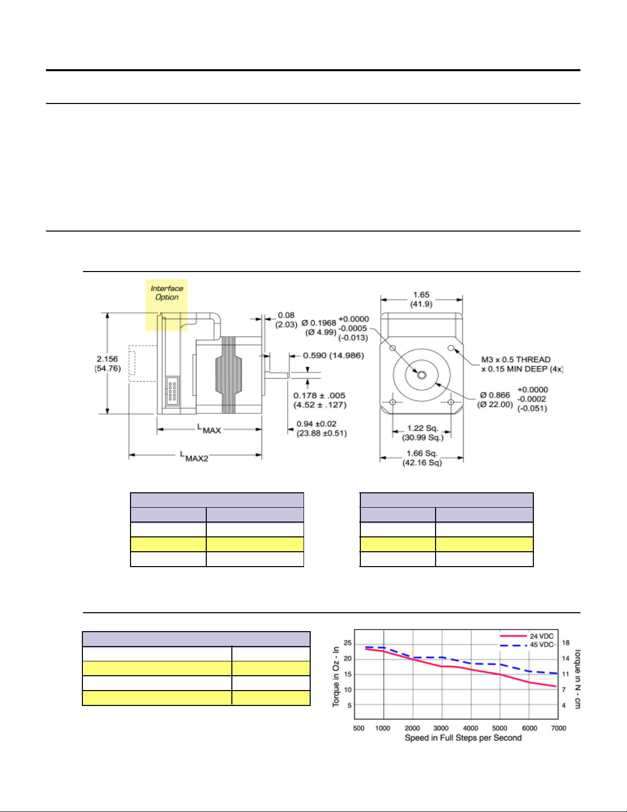
Figure 1.1: Rotary MDrive17 Motion Control Mechanical Specifications
MDrive Motion Control 1713 Motor Specs and Speed/Torque Curves
MDI1713
Holding Torque oz-in (N-cm) 32 (22.6)
Detent Torque oz-in (N-cm) 2.0 (1.4)
Rotor Inertia oz-in-sec2 (kg-cm2) 0.00053 (0.038)
Weight (Motor+Driver) oz (gm) 8.26 (234.2)
T able 1.1: Rotary MDI1713 Motor Specifications
MAX
)
Figure 1.2: Rotary MDrive Motion Contr ol 1713 Speed/Torque Data
Control Knob (L
Stack In ( mm)
1713 2.774 (69.71)
1715 2.965 (75.30)
1719 3.343 (84.92)
MAX2
)
6
Page 9
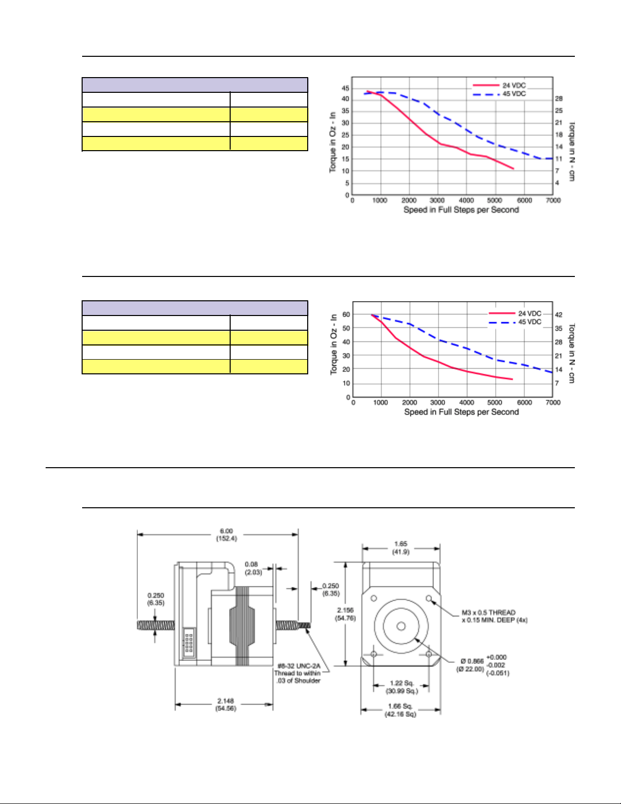
MDrive Motion Control 1715 Motor Specs and Speed/Torque Curves
MDI1715
Holding Torque oz-in (N-cm) 60 (42.4)
Detent Torque oz-in (N-cm) 2.5 (1.8)
Rotor Inertia oz-in-sec2 (kg-cm2) 0.00080 (0.057)
Weight (Motor+Driver) oz (gm) 10.42 (295.4)
T able 1.2: Rotary MDI1715 Motor Specifications
Figure 1.3: Rotary MDrive Motion Contr ol 1715 Speed/Torque Data
MDrive Motion Control 1719 Motor Specs and Speed/Torque Curves
MDI1719
Holding Torque oz-in (N-cm) 74.9 (52.9)
Detent Torque oz-in (N-cm) 4.0 (2.8)
Rotor Inertia oz-in-sec2 (kg-cm2) 0.0116 (0.082)
Weight (Motor+Driver) oz (gm) 11.80 (334.5)
T able 1.3: Rotary MDI1719 Motor Specifications
Linear Motor Specifications
Mechanical Specifications - Dimensions in Inches (mm)
Figure 1.4: Rotary MDrive Motion Control 1719 Speed/Torque Data
Figure 1.5: Linear Actuator MDrive17 Motion Control Mechanical Specifications
7
Page 10
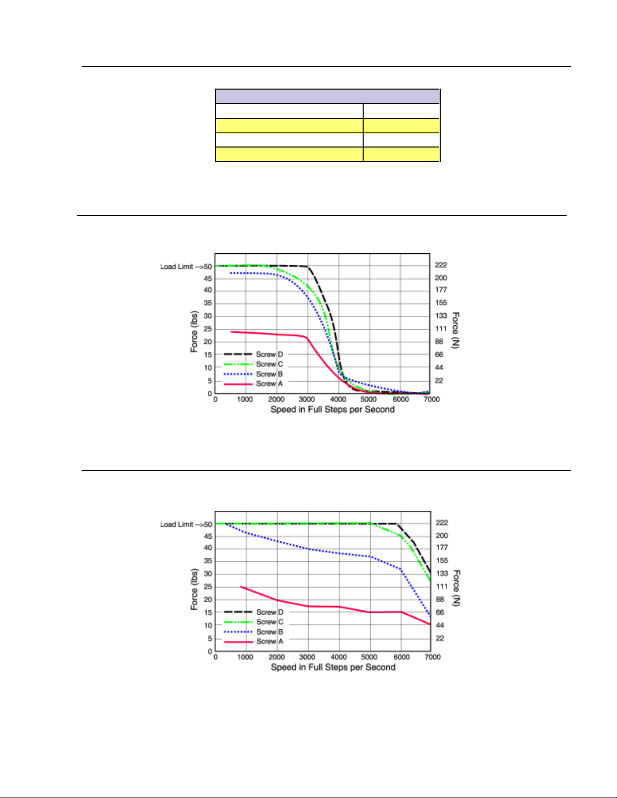
Linear Actuator MDrive Motion Control 1713 Specs and Speed-Force
Curves
MDI17 Linear Actuator
Maximum Thrust lbs (kg) 50 (22.7)
Maximum Screw Deflection ±1 °
Backlash inches (mm) 0.005 (0.127)
Weight (Motor+Driver) oz (gm) 9.2 (0.127)
T able 1.4: Linear Actuator MDrive17 Motion Contr ol Motor Specifications
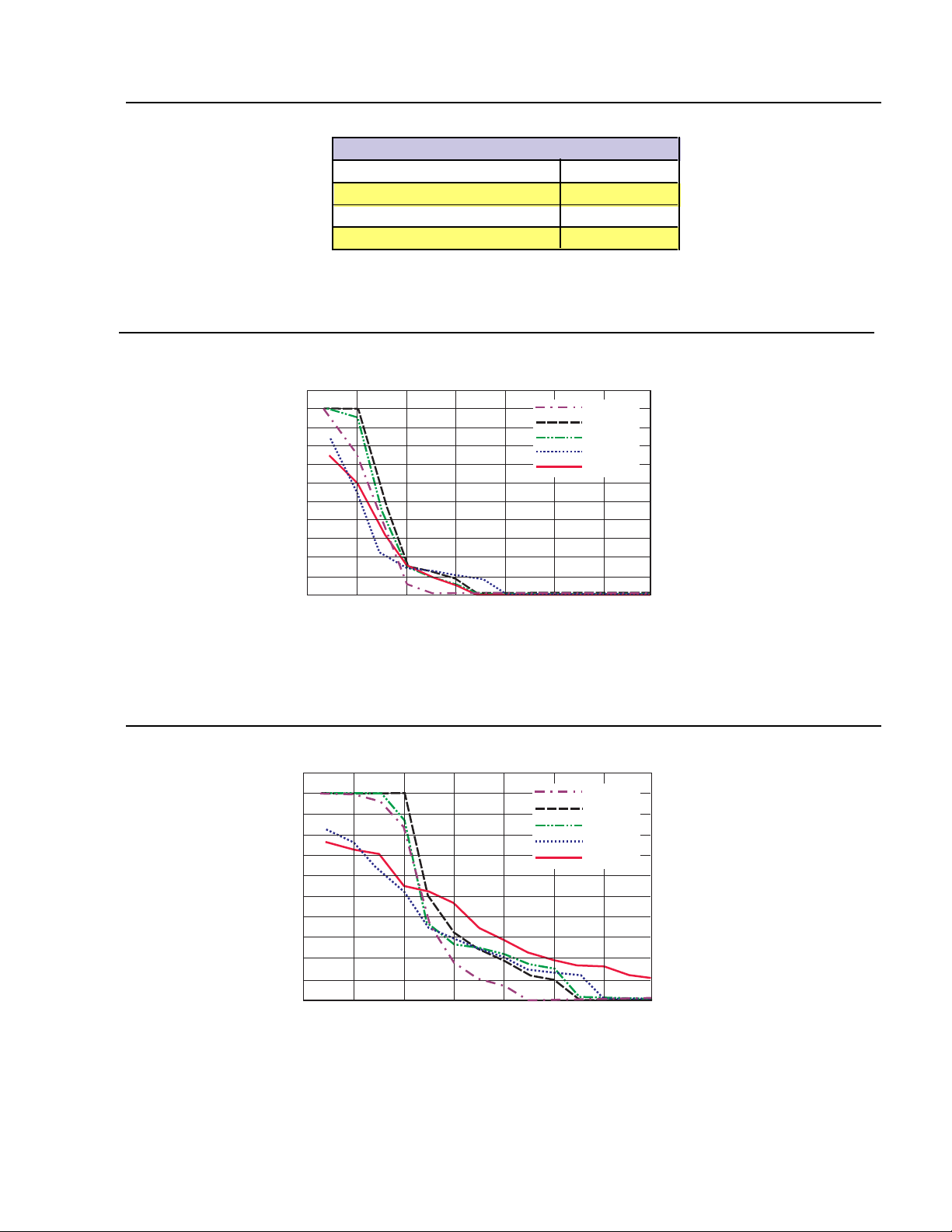
Speed-Force Curve: 24 VDC
Refer to Table 1. 5 for screw pitch information
Figure 1.6: Speed-Force Curve - 24VDC (100% Current)
Speed-Force Curve: 45 VDC
Refer to Table 1. 5 for screw pitch information
Figure 1.7: Speed-Force Curve - 45VDC (100% Current)
8
Page 11

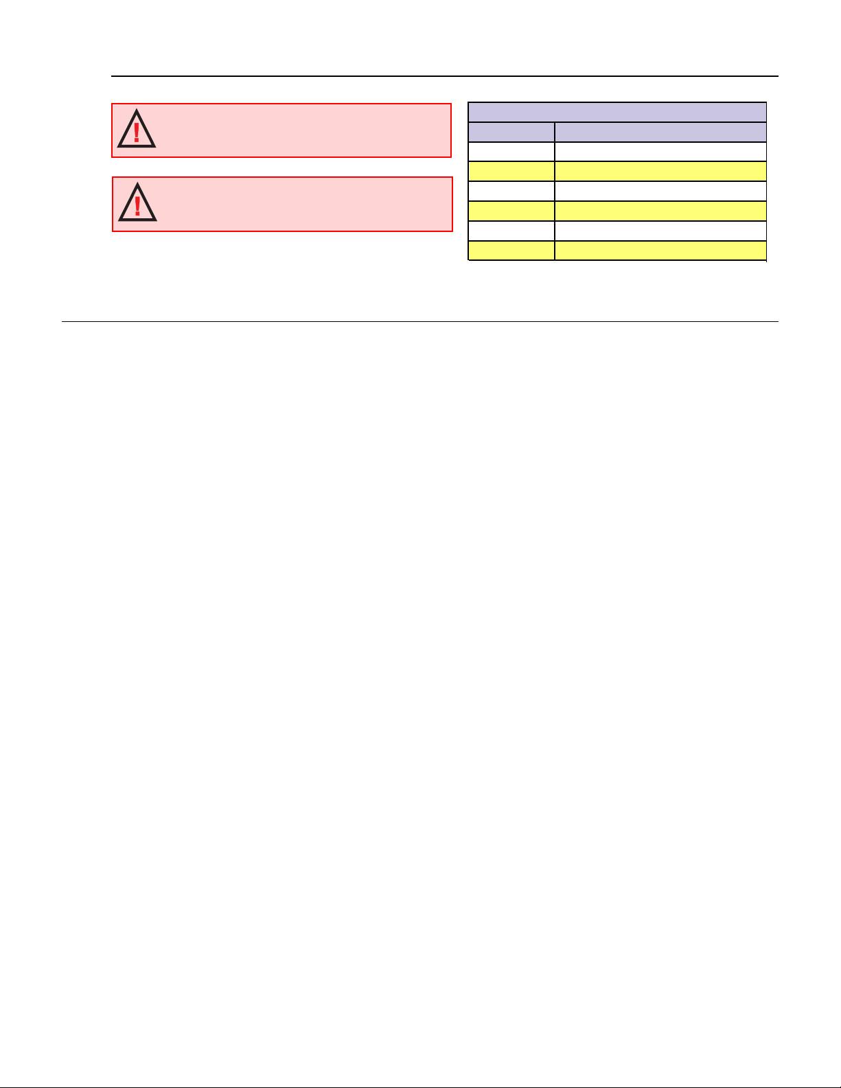
MDrive17 Motion Control ACME Screw
WARNING: The maximum axial load limit for the
MDrive17 Linear motor is 50 lbs (22.7 kg). Do not
exceed this rating!
WARNING: The ACME Screw MUST NOT deflect
more than ± 1 degree perpendicular to the motor face.
Additional support for radial loads may be required!
General Specifications
Input Voltage (+V)
Range ......................................................................................................................... +12 to +48 VDC
Analog Input
Resolution ................................................................................................................. 10 Bit
V oltage Range............................................................................................................. 0 to +5 Volts
Programmable I/O
Number ...................................................................................................................... 4
Interface Type ........................................................................................................... Open Collector
V oltage Range............................................................................................................. 0 to +24 VDC
Output Sink Current ................................................................................................. 700 mA
Protection .................................................................................................................. Over Temp., Short Circuit, Inductive Clamp
MDI17 ACME Screws
Screw Travel/Full Step - Inches (mm)
A 0.00125 (0.3175)
B 0.000625 (0.015875)
C 0.0003125 (0.079375)
D 0.00015625 (0.00396875)
Table 1.5: ACME Screws for the MDI17 Linear Actuator
Communication
Protocol ..................................................................................................................... RS-485, Full/Half Duplex SelecTable 1.
BAUD Rate ............................................................................................................... 4800, 9600, 19.2k, 38.0k, 115.2k
Motion
Microstep Resolution (Open Loop Configuration)
Number of Settings ................................................................................................... 14
Steps per Revolution ................................................................................................ 400, 800, 1000, 1600, 2000, 3200, 5000
6400, 10000, 12800, 25000, 25600, 50000
51200
Microstep Resolution (Closed Loop Configuration)
Steps per Revolution (Fixed).................................................................................... 51200
Encoder (Optional)
Type .......................................................................................................................... Internal, Magnetic
Resolution ................................................................................................................. 512 Lines/2048 counts per Revolution
Counters
Type .......................................................................................................................... Position(C1), Encoder (C2)
Resolution ................................................................................................................. 32 Bit
Edge Rate (Max)........................................................................................................ 5 MHz
Velocity
Range ......................................................................................................................... ±5,000,000 Steps per Second
Resolution ................................................................................................................. 1 Step per Second
Acceleration/Deceleration
Range ......................................................................................................................... 1.5 x 10⁹ Steps per Second
Resolution ................................................................................................................. 90.9 Steps per Second
2
2
9
Page 12

General Specifications
Software
Program and Data Storage ......................................................................................... Non-Volatile
User Program Space .................................................................................................. 767 Bytes
User Registers ........................................................................................................... 4 - 32 Bit
Math Functions ......................................................................................................... +, -, x, ÷, <>, =, <, <=, >, >=, AND, OR,
Branch Functions ...................................................................................................... Branch & Call (Conditional)
Predefined I/O Functions
Inputs ........................................................................................................................ Home, Limit +, Limit -, Go, Stop, Pause,
Outputs ..................................................................................................................... Moving, Fault
Trip Functions .......................................................................................................... Input, Position
Party Mode Node Addresses.................................................................................... 62
Encoder Functions .................................................................................................... Stall Detect, Position Maintenance,
Protection
Types ......................................................................................................................... Thermal
Power Supply Requirements
Each MDrive will require a maximum power supply current of 2A. Actual power supply current will depend upon the load and
duty cycle.
XOR, NOT
Jog +, Jog -, Analog Input
Find Index
Recommended IMS Power Supplies
Listed below are the power supplies recommended for use with both voltage ranges of the MDrive17 Motion Control.
Unregulated Linear Supply
Input Specifications
AC Input V oltage Range .................................................................................................... 102-132VAC/Optional 240VAC
Frequency ........................................................................................................................... 50-60Hz
Output Specifications
Voltage (Nominal - No Load)............................................................................................ 40 VDC
Current (Peak) ................................................................................................................... 4 Amps
Current (Continuous) ......................................................................................................... 2 Amps
Unregulated Switching Supply
Input Specifications
AC Input V oltage Range .................................................................................................... 102-132VAC
Frequency ........................................................................................................................... 50-60Hz
Output Specifications
Voltage (Nominal - No Load)............................................................................................ 45 VDC
Current (Peak) ................................................................................................................... 3 Amps
Current (Continuous) ......................................................................................................... 1.5 Amps
Thermal Specifications
Because the MDrive consists of two core components, a drive and a motor, close attention must be paid to the thermal environment
where the device is used. The following maximum temperatures apply to the MDrive17:
Heatsink Temperature
Max.................................................................................................................................... 85°C
Motor Temperature
Max.................................................................................................................................... 100°C
IP404(MDI17)
ISP200-4(MDI17)
/Optional 240VAC
10
Page 13

Section 1.3
Introduction to the MDrive23 Motion Control
Introduction to the MDrive23 Motion Control
The MDrive23 Motion Control offers the system designer a low-cost, intelligent motion controller integrated with a NEMA 23 high
torque stepping motor and a +12 to +48 VDC microstepping drive.
The MDrive23 Motion Control adds a versatile array of functions by combining a complete programmable motion controller with
our already compact and cost effective standard MDrive23, adding little cost and no increase in size. Standard offerings include four
5 to 24 volt programmable I/O points, one 10-bit 0 to 5 volt analog input, 0 to 5 MHz step clock rate, microstep resolution up to
51,200 steps per revolution and a full featured easy-to-program instruction set.
The MDrive23 Motion Control communicates using the RS-485 communications protocol, this allows for point-to-point or multidrop communications using one communications port. Addressing and hardware support up to 62 MDrive nodes in a system. The
communications BAUD rate is software selectable and ranges from 4.8 kbps to 115 kbps.
The MDrive23 is also available with an optional closed loop control. The closed loop configuration adds a 512 line (2048 count)
internal magnetic rotary encoder with index mark without increasing the length of the unit. Closed loop configuration adds position
maintenance, stall detection and find index mark.
A vailable motor configurations include: single shaft, double shaft with control knob, and long life ACME screw linear actuator .
Rotary versions are available in three stack lengths: 18, 22 & 31. Interface connections are accomplished using either a 7 position
terminal block or optional 12” flying leads.
Feature Summary
! Integrated Microstepping Drive/Motion Controller with Optional Encoder/NEMA 23 High Torque Stepping Motor
! +12 to +48VDC Input Voltage
! Low Cost
! Extremely Compact
! Available Configurations: Single Shaft*, Linear Actuator, Integral Encoder*, Double Shaft with Knob for Manual
! Three Motor Stack Lengths Available*
! Single Power Supply
! Microstep Resolution up to 51,200 Steps Per Revolution
! Open Loop or Optional Closed Loop Control
! Programmable Motor Run and Hold Current Settings
! Four 5 to 24 VDC Programmable I/O Points
! One Analog 10 Bit, 0 to 5 Volt Analog Input
! 0 to 5 MHz Step Clock Rate, Selectable in 0.59 Hz Increments
! RS-485 Communications Protocol
! Communications BAUD Rate Selectable from 4.8 kbps to 115 kbps
! 62 Software Addresses for Multidrop Communications
! Simple 1 and 2 Character Programming Instructions
! Pluggable Terminal Strip or 12” Flying Lead Interface
! Optional Integrated RS-232 to RS-485 Converter/Communications Cable
*Rotary Motor Only
Positioning*
11
Page 14

Section 1.4
5
(
)
500
(
)
SQ.
EQ. SPAC
A
2
.
0.230 .005
(
)
0
)
MDrive23 Motion Control Specifications
Section Overview
This section contains mechanical, motor and electrical specifications specific to each version of the MDrive23 Motion Control.
Shown are:
!
! Linear Motor Specifications
! General Specifications
! Power Supply Requirements
! Thermal Specifications
Rotary Motor Specifications
Mechanical Specifications - Dimensions in Inches (mm)
Rotary Motor Specifications
Interface
Option
1.62
41.28
0.060
(1.53)
0.810 ± .030
(20.57 ±.76)
0.590
(14.86)
1.
38.10
4 x Ø 0.205 (5.21)
±.010 (.25) HOLES
ED ON
.625 (66.68) DBC
2.907
(73.84)
L
MAX
L
MAX2
Standard Rotary Motor (L
MAX
)
Stack In (mm)
2218 2.632 (66.85)
2222 3.000 (76.20)
2231 3.960 (100.58)
5.84
.2500 (6.35
Ø
0.2495 (6.34)
Ø 1.500 ±.002
(Ø 38.10 ±.05)
.127
1.860
(47.24 SQ.)
2.22 SQ.
(56.39 SQ.)
Control Knob (L
MAX2
)
Stack In ( mm)
2218 3.088 (78.44)
2222 3.537 (89.84)
2231 4.416 (112.17)
Figure 1.8: Rotary MDrive23 Motion Control Mechanical Specifications
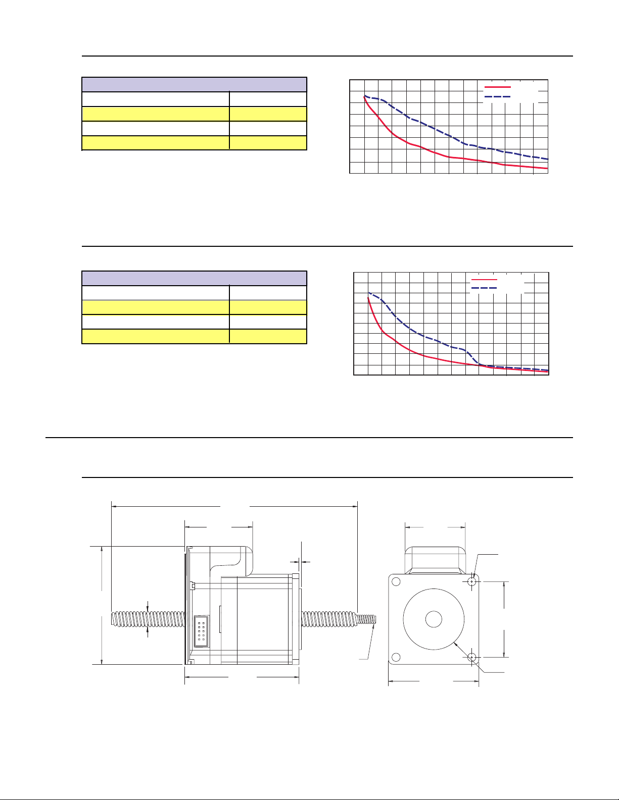
MDrive Motion Control 2218 Motor Specs and Speed/Torque Curves
MDI2218
Holding Torque oz-in (N-cm) 90 (64)
Detent Torque oz-in (N-cm) 3.5 (2.5)
Rotor Inertia oz-in-sec2 (kg-cm2) 0.0025 (0.18)
Weight (Motor+Driver) oz (gm) 20.1 (569.8)
T able 1.6: Rotary MDI2218 Motor Specifications
70
60
50
40
30
20
Torque in Oz - In
10
0
0 1000 2000 3000 4000 5000 6000 7000
Speed in Full Steps per Second
24 VDC
45 VDC
49
Torque in N - cm
42
35
28
21
14
7
Figure 1.9: Rotary MDrive Motion Contr ol 2218 Speed/Torque Data
12
Page 15
MDrive Motion Control 2222 Motor Specs and Speed/Torque Curves
5
(
)
Q.
(
)
(
)
(
)
Q
A
.
Ø
5
A
(
)
OF SHOU
R
MDI2222
Holding Torque oz-in (N-cm) 144 (102)
Detent Torque oz-in (N-cm) 5.6 (3.92)
Rotor Inertia oz-in-sec2 (kg-cm2) 0.0037 (0.26)
Weight (Motor+Driver) oz (gm) 24.4 (691.7)
T able 1.7: Rotary MDI2222 Motor Specifications
140
120
100
80
60
40
Torque in Oz - In
20
0
0 1000 2000 3000 4000 5000 6000 7000
Speed in Full Steps per Second
Figure 1.10: Rotary MDrive Motion Contr ol 2222 Speed/Torque Data
MDrive Motion Control 2231 Motor Specs and Speed/Torque Curves
MDI2231
Holding Torque oz-in (N-cm) 239 (169)
Detent Torque oz-in (N-cm) 9.7 (6.86)
Rotor Inertia oz-in-sec2 (kg-cm2) 0.0065 (0.46)
Weight (Motor+Driver) oz (gm) 38.5 (1091.5)
T able 1.8: Rotary MDI2231 Motor Specifications
225
200
175
150
125
100
75
Torque in Oz - In
50
25
0
0 1000 2000 3000 4000 5000 6000 7000
Speed in Full Steps per Second
24 VDC
45 VDC
24 VDC
45 VDC
99
Torque in N - cm
85
71
56
42
28
14
159
141
124
Torque in N - cm
106
88
71
53
35
18
Linear Motor Specifications
Mechanical Specifications - Dimensions in Inches (mm)
6.000
(152.40)
1.62
41.28
0.375
2.907
(73.84)
(9.525)
2.630
(66.80)
Figure 1.11: Rotary MDrive Motion Control 2231 Speed/Torque Data
1.500
38.10
4 x Ø 0.205 (5.21)
0.060
(1.53)
1/4-20 UNC-2
THREAD TO
WITHIN .050
LDE
1.3
2.22 S
56.39 SQ.
±.010 (.25) HOLES
E
. SPACED ON
2.625 (66.68) DBC
1.860 SQ..
47.24 SQ.
00 ±.002
1.
(Ø 38.10 ±.05)
Figure 1.12: Linear Actuator MDrive23 Motion Control Mechanical Specifications
13
Page 16
Linear Actuator MDrive Motion Control 2218 Specs and Speed-Force
Curves
MDI23 Linear Actuator
Maximum Thrust lbs (kg) 200 (90.7)
Maximum Screw Deflection ±1 °
Backlash inches (mm) 0.005 (0.127)
Weight (Motor+Driver) oz (gm) 20.4 (578.3)
T able 1.9: Linear Actuator MDrive23 Motion Contr ol Motor Specifications
Speed-Force Curve: 24 VDC
Refer to Table 1.10 for screw pitch information
200
180
160
140
120
100
80
60
40
20
Force (lbs) Load Limit 200 lbs
0
0 1000 2000 3000 4000 5000 6000 7000
Speed in Full Steps per Second
Figure 1.13: Speed-Force Curve - 24VDC (100% Current)
Speed-Force Curve: 45 VDC
Refer to Table 1.10 for screw pitch information
200
180
160
140
120
100
80
60
40
Force (lbs) Load Limit 200 lbs
20
0
0 1000 2000 3000 4000 5000 6000 7000
Screw E
Screw D
Screw C
Screw B
Screw A
Scre w E
Scre w D
Scre w C
Scre w B
Scre w A
Speed in Full Steps per Second
890
Force (N)Load Limit 890N
801
712
623
534
445
356
267
178
89
890
Force (N)Load Limit 890N
801
712
623
534
445
356
267
178
89
Figure 1.14: Speed-Force Curve - 45VDC (100% Current)
14
Page 17
MDrive23 Motion Control ACME Screw
WARNING: The maximum axial load limit for the
MDrive23 Linear motor is 200 lbs (90.7 kg). Do not
exceed this rating!
WARNING: The ACME Screw MUST NOT deflect
more than ± 1 degree perpendicular to the motor face.
Additional support for radial loads may be required!
General Specifications
Input Voltage (+V)
Range ......................................................................................................................... +12 to +48 VDC
Analog Input
Resolution ................................................................................................................. 10 Bit
V oltage Range............................................................................................................. 0 to +5 Volts
Programmable I/O
Number ...................................................................................................................... 4
Interface Type ........................................................................................................... Open Collector
V oltage Range............................................................................................................. 0 to +24 VDC
Output Sink Current ................................................................................................. 700 mA
Protection .................................................................................................................. Over Temp., Short Circuit, Inductive Clamp
MDI23 ACME Screws
Screw Travel/Full Step - Inches (mm)
F 0.002 (0.0508)
A 0.001 (0.0254)
B 0.000833 (0.0211582)
C 0.0005 (0.0127)
D 0.0004167 (0.00793750)
E 0.0003125 (0.0079375)
T able 1.10: ACME Screws for the MDI23 Linear Actuator
Communication
Protocol ..................................................................................................................... RS-485, Full/Half Duplex Selectable
BAUD Rate ............................................................................................................... 4800, 9600, 19.2k, 38.0k, 115.2k
Motion
Microstep Resolution (Open Loop Configuration)
Number of Settings ................................................................................................... 14
Steps per Revolution ................................................................................................ 400, 800, 1000, 1600, 2000, 3200, 5000
6400, 10000, 12800, 25000, 25600, 50000
51200
Microstep Resolution (Closed Loop Configuration)
Steps per Revolution (Fixed).................................................................................... 51200
Encoder (Optional)
Type .......................................................................................................................... Internal, Magnetic
Resolution ................................................................................................................. 512 Lines/2048 counts per Revolution
Counters
Type .......................................................................................................................... Position(C1), Encoder (C2)
Resolution ................................................................................................................. 32 Bit
Edge Rate (Max)........................................................................................................ 5 MHz
Velocity
Range ......................................................................................................................... ±5,000,000 Steps per Second
Resolution ................................................................................................................. 1 Step per Second
Acceleration/Deceleration
Range ......................................................................................................................... 1.5 x 10⁹ Steps per Second
Resolution ................................................................................................................. 90.9 Steps per Second
2
2
15
Page 18

General Specifications
Software
Program and Data Storage ......................................................................................... Non-Volatile
User Program Space .................................................................................................. 767 Bytes
User Registers ........................................................................................................... 4 - 32 Bit
Math Functions ......................................................................................................... +, -, x, ÷, <>, =, <, <=, >, >=, AND, OR,
Branch Functions ...................................................................................................... Branch & Call (Conditional)
Predefined I/O Functions
Inputs ........................................................................................................................ Home, Limit +, Limit -, Go, Stop, Pause,
Outputs ..................................................................................................................... Moving, Fault
Trip Functions .......................................................................................................... Input, Position
Party Mode Node Addresses.................................................................................... 62
Encoder Functions .................................................................................................... Stall Detect, Position Maintenance,
Protection
Types ......................................................................................................................... Thermal
Power Supply Requirements
Each MDrive will require a maximum power supply current of 2A. Actual power supply current will depend upon the load and
duty cycle.
XOR, NOT
Jog +, Jog -, Analog Input
Find Index
Recommended IMS Power Supplies
Listed below are the power supplies recommended for use with both voltage ranges of the MDrive23 Motion Control.
Unregulated Linear Supply
Input Specifications
AC Input V oltage Range .................................................................................................... 102-132VAC/Optional 240V AC
Frequency ........................................................................................................................... 50-60Hz
Output Specifications
Voltage (Nominal - No Load) ............................................................................................ 40 VDC
Current (Peak) ................................................................................................................... 4 Amps
Current (Continuous) ......................................................................................................... 2 Amps
Unregulated Switching Supply
Input Specifications
AC Input V oltage Range .................................................................................................... 102-132VAC
Frequency ........................................................................................................................... 50-60Hz
Output Specifications
Voltage (Nominal - No Load) ............................................................................................ 45 VDC
Current (Peak) ................................................................................................................... 3 Amps
Current (Continuous) ......................................................................................................... 1.5 Amps
Thermal Specifications
Because the MDrive consists of two core components, a drive and a motor, close attention must be paid to the thermal environment
where the device is used. The following maximum temperatures apply to the MDrive23:
Heatsink Temperature
Max.................................................................................................................................... 85°C
Motor Temperature
Max.................................................................................................................................... 100°C
IP404(MDI23)
ISP200-4(MDI23)
/Optional 240VAC
16
Page 19

Part 2: Connecting, Configuring
and Programming the
MDrive Motion Control
17
Page 20

Intentionally Left Blank
18
Page 21
Section 2.1
Interfacing the MDrive Motion Control
Section Overview
This section will acquaint the user with connecting and using the MDrive Motion Control.
!
! Pin Configuration and Descriptions
! Interfacing Power
! Interfacing RS-485 Communications
! Interfacing Digital I/O
! Interfacing Analog Input
Layout and Interface Guidelines
Logic level cables must not run parallel to power cables. Power cables will introduce noise into the logic level cables and make your
system unreliable.
Logic level cables must be shielded to reduce the chance of EMI induced noise. The shield needs to be grounded at the signal source
to earth. The other end of the shield must not be tied to anything, but allowed to float. This allows the shield to act as a drain.
Power supply leads to the driver need to be twisted. If more than one driver is to be connected to the same power supply, run
separate power and ground leads from the supply to each driver.
Recommended Wiring
Layout and Interface Guidelines
The following wiring/cabling is recommended for use with the MDrive Motion Control:
Power
Belden Part# 9740 or equivalent 18 Gauge
Logic Wiring (I/O, Communications)
Wire Size .............................................................................................................. 20-22 AWG
General Practices
The following wire strip length is recommended:
Wire Strip Length................................................................................................. 0.250” (6.0 mm)
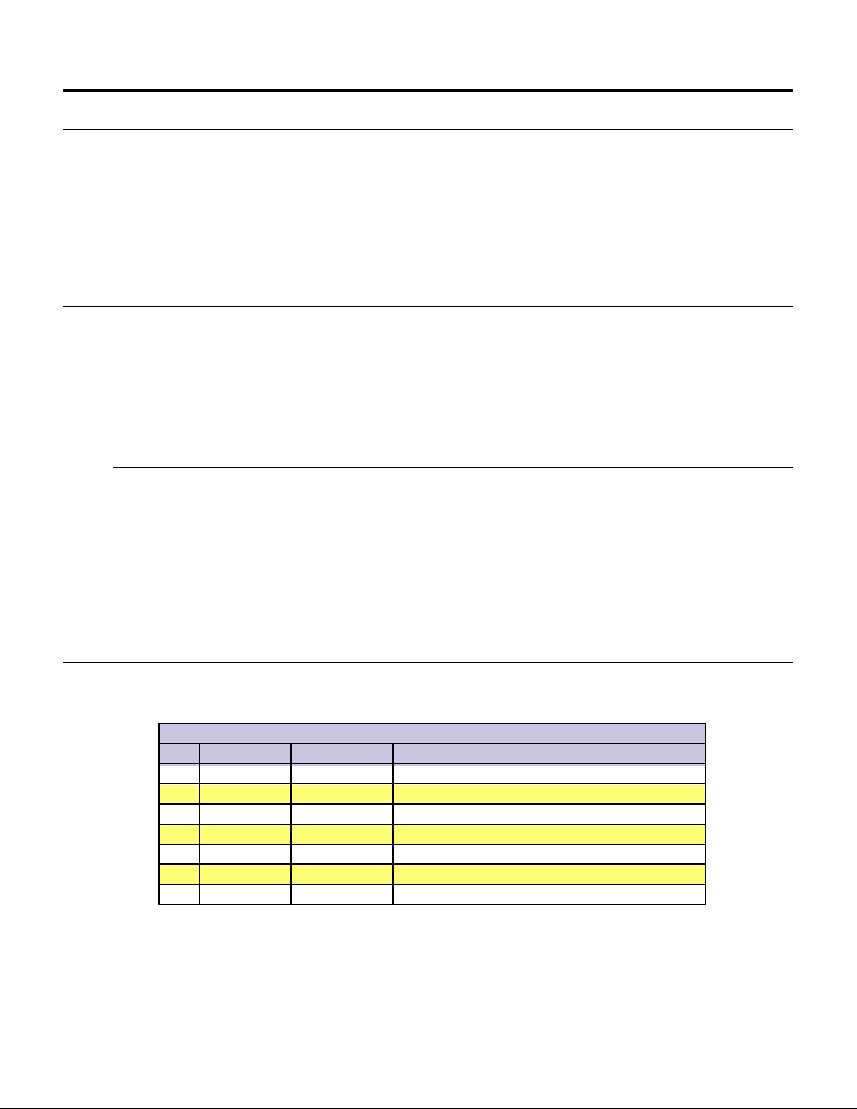
Pin Configuration and Descriptions
Connector P1
Pin # Flying Lead Function Description
1 White/Yellow I/O1 Open Collector I/O Point #1, +5 to +24VDC
2 White/Orange I/O2 Open Collector I/O Point #2, +5 to +24VDC
3 White/Violet I/O3 Open Collector I/O Point #3, +5 to +24VDC
4 White/Blue I/O4 Open Collector I/O Point #4, +5 to +24VDC
5 Green Analog Input 10 Bit, 0 to 5V Analog Input
6 Black GND Ground
7 Red +V +12 to +48 VDC Power Supply Input
T able 2.1: P1 Pin Configuration and Description
19
Page 22

Pin # Function Description
1- 5 N/C Reserved
6 RX+ RS-485 Receive +
7 RX- RS-485 Receive 8 TX- RS-485 Transmit 9 TX+ RS-485 Transmit +
10 GND Communications Ground
Interfacing Power
Connector P2 - 10 Pin Header
T able 2.2: P2 Pin Configuration and Description
An advantage of the MDrive Motion Control is
that only a single +12 to +48VDC unregulated
linear or unregulated switching power supply is
required to power the control circuitry and motor
power.
A maximum of 2A output is required from the
supply for each MDrive. Note that the actual
+12 to +48 VDC
Unregulated
Linear or
Unregulated
Switching
Power Supply
power required will be based upon the load and
duty cycle.
Wiring should be accomplished using shielded
twisted pair Belden Part# 9740 or equivalent 18
PWR GND
+VDC
OUTPUT
Gauge. The shield should be attached to earth at
the power supply end and left floating at the
MDrive end.
Interfacing RS-485 Communications
The MDrive Motion Control
communicates to the host using the
RS-485 protocol. Communications
may be configured as either half or
full duplex using the EM (Echo
Mode) Instruction. RS-485 may be
used in two ways: either to communicate to a single MDrive Motion
Control, or to address up to 62
individually named MDrive nodes in a
multidrop system.
MDrive23 Motion Control
PIN 1
Shielded Twisted Pair 18 AWG
Earth
Figure 2.1: Power Supply Interface
Single MDrive
Optionally available for the MDrive
Motion Control is a communications
cable, IMS P/N MD-CC200-000,
which has built-in RS-232 to RS-485
conversion circuitry . This will allow
you to connect the serial port of your
PC directly to the MDrive Motion
Control.
Figure 2.2: RS-485 Interface, Single MDrive Motion Control
20
Page 23

Multiple MDrive Motion Control System (Party Mode)
In systems with multiple controllers it is necessary to communicate with the control modules using party mode (PY=1) of operation. The MDrive Motion Control nodes in the system are configured in software for this mode of operation by setting the Party
Flag (PY) to True (1). It is necessary for all of the nodes in a system to have this configuration selected. When operating in party
mode each MDrive Motion Control in the system will need a unique address, or name, to identify it in the system. This is
accomplished by using the software command DN, or Device Name. For example, to set the name of an MDrive to “A” you would
use the following command: DN=65 or DN=”A” (65 is the ASCII decimal equivalent of uppercase A). The factory default name is
“!”. The asterisk character “*” is used to issue global commands to every device in the system. See Appendix A for ASCII table.
In setting up your system for party operation the most practical approach would be to observe the following steps:
1. Connect the first MDrive Motion Control to the Host PC configured for Single Mode Operation.
2. Establish communications. Using the command DN name the MDrive Motion Control. This can be any upper or
3. Set the party flag PY=1. Remove power.
4. Connect the next MDrive Motion Control in the system, set the party flag to true.
5. Establish communications with this module using the factory default name “!”. This name cannot be reused.
6. Repeat the last two steps for each additional MDrive in the system.
lower case ASCII character or number 0-9.
Rename and save the new name. Remove power.
Figure 2.3: RS-485 Interface, Multiple MDrive Motion Control System
21
Page 24

Interfacing the Digital I/O
The MDrive Motion Control comes standard with a set of four (4) open collector +5 to +24VDC I/O point which may be
programmed individually as either general purpose or dedicated inputs or outputs, or collectively as a group.
The digital I/O may be defined as either active HIGH or active LOW . When the I/O is configured as active HIGH, the level is +5 to
+24 VDC and the state will be read/set as a “1”. If the level is 0 VDC then the state will be read/set as “0”. Inversely, if co nfigured as
active LOW, then the state of the I/O will be read/set as a “1” when the level is LOW, and a “0” when the level is HIGH. The active
HIGH/LOW state is configured by the third parameter of the I/O Setup (S1-4) variable, which is explained further on. The goal of this
I/O configuration scheme is to maximize compatibility between the MDrive Motion Control and standard sensors and switches.
The MDrive Motion Control’s I/O scheme is a powerful tool for machine and process control.
Uses of the Digital I/O
The I/O may be utilized to receive input from external devices such as sensors, switches or PLC outputs. When configured as outputs,
devices such as relays, solenoids, LED’s and PLC inputs may be controlled from the MDrive Motion Control.
Each I/O point may be individually programmed to any one of 9 dedicated input functions, 3 dedicated output functions, or as
general purpose inputs or outputs. The I/O may be addressed individually, or as a group. The active state of the line or group may
also be set. All of these possible functions are accomplished with of the I/O Setup Variable (S1-4).
Interfacing Inputs
The MDrive Motion Conrol inputs may be interfaced to a variety of sinking devices. A single input may be programmed to be a
general purpose user input, or to one of nine dedicated input functions. These then may be programmed to have an active state of
either HIGH or LOW.
Additionally the inputs may read as a group using the “IN” keyword. This will display as a decimal between 0 and 15 representing
the 4 bit binary number. Used thus Input 1 is the Least Significant Bit (LSB) and Input 4 will be the Most Significant Bit (MSB).
Interfacing a Single Input Examples
Input Functions
S<point>= Function Active
0 General Purpose 0/1
1 Home 0/1
2 Limit + 0/1
3 Limit - 0/1
4 G0 0/1
5 Soft Stop 0/1
6 Pause 0/1
7 Jog + 0/1
8 Jog - 0/1
10 Index (encoder only) 0/1
T able 2.3: Input Functions
Figure 2.4: Input Interfaced to a Switch
Figure 2.5: Input Interfaced to a PLC
22
Page 25

Interfacing Inputs as a Group Example
+5VDC
Sample Software Configuration
'set inputs to user inputs active low,
S1=0,0
S2=0,0
S3=0,0
S4=0,0
PR IN 'Read BCD State of Input Group
Figure 2.6: TTL Interface to Input Group
MDrive23 Motion Control
PIN 1
Truth T able - I/O Used as a Group
DEC IO4 IO3 IO2 IO1
00000
10001
20010
30011
40100
50101
60110
70111
81000
91001
101010
111011
121100
131101
141110
151111
Table 2.4: I/O Group Truth Table
23
Page 26

Interfacing Outputs
PIN 1
MDrive23 Motion Control
Sample Software Configuration
'set outputs to user outputs active low,
S1=16,0
S2=16,0
S3=16,0
S4=16,0
OT=<0-15> `Set outputs as 1 value
+5 to +24VDC
The MDrive Motion Control Outputs may be configured as either general purpose or set to one of two dedicated functions, Fault or
Moving. These outputs will sink up to 700 mA max and may be connected to +5 to +24VDC. Note that a current limiting resistor may
be required to limt the current to 700 mA.
As with the inputs the MDrive Motion Control Outputs may be used singularly or collectively as a group.
Interfacing a Single Output Examples
+5 to +24 V
Sample Software Configuration #1: FAULT
S4=18,0 'Set IO4 to Fault, Active State=LOW
Sample Software Configuration #2: MOVING
S4=17,0 'Set IO4 to Moving, Active State=LOW
(LED will illuminate when Axis is moving)
Figure 2.7: Output Interfaced to an LED
+5 to +24 V
*External Resistor may be needed to
limit output sink current to 700mA
MDrive23 Motion Control
PIN 1
MDrive23 Motion Control
PIN 1
Input Functions
S<point>= Function Active
16 General Purpose 0/1
17 Fault 0/1
18 Moving 0/1
T able 2.5: Output Functions
Sample Software Configuration #1: FAULT
S4=18,0 'Set IO4 to Fault, Active State=LOW
Sample Software Configuration #2: General Purpose
S4=16,0 'Set IO4 to General Purpose, Active State=LOW
Figure 2.8: Output Interfaced to a Relay
Interfacing Outputs as a Group Example
To write to the outputs as a group the OT instruction is
used. This will give you a binary output of 0000 to 1111
from a decimal entry of 0-15. Output 1 will be the Least
Significant Bit (LSB), Output 4 will be the Most Significant
Bit (MSB).
See Table 2.4 for Truth Table.
Figure 2.9: Outputs Interfaced to LED’s as a Group
24
Page 27

Interfacing the Analog Input
The analog input of the MDrive Motion Control is a 0 to 5V, 10 bit resolution input. This offers the user the ability to receive input
from temperature, pressure or other forms of sensors, and then control events based upon the input.
The value of this input will be read using the I5 instruction, which has a range of 0 to 1024, where 0 = 0 volts and 5 = 5.0 volts. You
may then use the program branch (BR) or subroutine call (CL) instructions to control events within the system.
Sample Usage
‘*********Main Program***********
PG 100 ‘start prog. at address 100
LB A1 ‘label program A1
CL A2, I5<500 ‘Call Sub A2, If I5 is less than 500
CL A3, I5>524 ‘Call Sub A3, If I5 is greater than 524
BR A1 ‘loop to A1
E ‘End
PG ‘Exit program
‘*********Subroutines************
LB A2 ‘label subroutine A2
MA 2000 ‘Move Absolute 2000 steps
H ‘Hold program execution until motion ceases
RT ‘return from subroutine
LB A3 ‘label subroutine A3
MA -2000 ‘Move Absolute -2000 steps
H ‘Hold program execution until motion ceases
RT ‘return from subroutine
Figure 2.10: Analog Input Interface
25
Page 28

Section 2.2
MDrive Motion Control Software Introduction
Section Overview
This section will acquaint the user with basics of MDrive Motion Control Programming
!
! Upgrading the MDrive Firmware
! The MDrive Program
Installing and Using IMS Terminal
System Requirements
! IBM Compatible PC.
! Windows 95/98 or Windows NT4.0 SP6, Windows 2000 SP2, Windows XP
! 10 MB hard drive space.
! A free serial communications port.
Installation
The IMS T erminal software is a programming/communications interface. This program was created by IMS to simplify programming and upgrading the MDrive Motion Control. The IMS Terminal is also necessary to upgrade the software in your MDrive
Motion Control. These updates will be posted to the IMS website at www.imshome.com as they are made available.
Installing IMS Terminal Software
To install the IMS Terminal to your hard drive, insert the IMS CD into your CD-ROM Drive. The installation front-end will
automatically open.
Follow the on-screen instructions to complete the installation.
Figure 2.11: IMS Terminal W indow
26
Page 29

1) To open the IMS Terminal select Start > Programs > IMS Terminal > IMS T erminal.
2) Click the File Menu Item “Edit>Preferences”.
3) Click the “Comm Settings” tab.
4) Select the Communications Port that you will be using with your MDrive Motion Control.
5) The BAUD rate is already set to the MDrive Motion Control default. Do not change this setting until you have
6) The “Window Size” settings are strictly optional. You may set these to whatever size is comfortable to you.
7) Click “OK”. The settings will be automatically saved upon a normal shutdown.
8) Apply power to the MDrive Motion Control. A sign-on message should appear in the terminal window.
established communications with the MDrive Motion Control.
If you can see this sign-on message then you are up and running! If the sign-on banner does not appear, try using a software reset:
hold down the “Ctrl” key and press “C” (^C). If the sign-on banner still does not appear then there may be a problem with either
the hardware or software configuration of the MDrive Motion Control or Host PC.
Using the IMS Terminal Software
The IMS Terminal software is an easy to setup and use interface for MDrive Motion Control programming. It is also required to
upgrade the firmware in the MDrive Motion Control.
Configuring Communications Settings
The communications settings are configured by means of the
“Preferences Dialog”. This dialog is accessed through the
“Edit > Preferences” menu item or by clicking the “Preferences” icon on the toolbar. The preferences dialog gives the
user the ability to set the format for text size, font and
color, as well as general communications settings. It is set
by default to the optimum communications settings for the
MDrive Motion Control. If you change the BAUD rate
setting for the MDrive Motion Control, power will have to
be cycled for the change to take effect. Ensure that the IMS
Terminal preferences are adjusted for the new BAUD
settings.
Downloading a Program to the MDrive
Motion Control
There are two ways to download programs to the MDrive
Motion Control:
1] Directly from the text editor window of
2] From a text file located on a hard drive or
the IMS T erminal.
removable disk.
To download a program from the text editor window click
the menu item “Transfer > Download”. The download
Figure 2.12: IMS Terminal Preferences
dialog will open. Select the “Source Type > Edit Window”
option, click download. The program will transfer to the MDrive Motion Control.
Programs can be downloaded to the MDrive Motion Control from a text file by selecting “Source Type > File” on the dialog and
typing in a drive location:\file name in the “File Name” box on the dialog, or browsing to the file location.
Uploading a Program From the MDrive Motion Control
Programs may also be uploaded from the MDrive Motion Control in two ways:
1] Directly to the text editor window of the IMS Terminal.
2] To a text file located on a hard drive or removable disk.
To upload a program to the text editor window click the menu item “Transfer > Upload”. The upload dialog will open. Select the
“Destination Type > Edit Window” option, click “Upload”. The program will transfer from the MDrive Motion Control.
Programs may be uploaded from the MDrive Motion Control to a text file by selecting “Destination Type > File” on the dialog and
typing in a drive location:\file name in the “File Name” box on the dialog.
27
Page 30

Setting the Programmable Function Keys
The IMS Terminal features the capability of programming up to 10 function keys, a feature typically found in more advanced
terminal programs. These can be set to provide quick access to commonly used MDrive Immediate mode commands, execute
programs, or even hold entire MDrive programs as there is no character limit for each function.
A fly-out dialog can be brought up by clicking the arrow on the right of the function key “Contents” field. This enables the
programmer to embed common ASCII control codes in the function key text string.
To access the function key setup dialog, right-click the function key area on the terminal window.
To setup the function keys:
1] Enter a caption in the “Caption” text field, this will be displayed on the function button.
2] Enter the text string consisting of MDrive Motion Control commands and ASCII control codes. Remember to
3] Click “Done” to set the function.
terminate each command with a line feed (^M) and an appropriate pause time (typically 50 msec, ^p).
Upgrading the MDrive Motion Control Firmware
1] Connect power to the MDrive Motion Control.
2] Open the IMS Terminal Software.
3] Select the Terminal screen.
4] Click the “Upgrade” menu item on the Menu bar.
5] Enter 2956102 in the Type Number field.
6] Click Next, follow the instructions.
7] Cycle power on the MDrive Motion Control.
Figure 2.13: IMS Terminal Upgrader Window
28
Page 31

MDrive Motion Control Programming
The MDrive programming language consists of simple 1-2 character mnemonics.
Operational Modes
There are two operational modes for the MDrive. Immediate and Program:
1] Immediate: Commands are issued and executed directly to the MDrive Motion Control by user entry into the terminal
2] Program: Commands and processes are run from within an MDrive program. This mode is also used for program
window.
entry.
Basic Components of MDrive Motion Control Software
Instructions
An instruction results in an action, there are three types:
Motion
Motion instructions are those that result in the movement of a motor. The syntax of these commands are as such: first type the
command followed by a space, and then the velocity or position data. For example, MA 2000 will move the motor to position 2000.
I/O
An I/O instruction results in the change of parameters or the state of an Input or Output. The syntax of these commands are as
such: first type the command followed by a space, then the I/O #, then an equal sign, then the data. Example: PR I1 will read the
state of input 1, O2=0 will set output 2 to 0.
Program
A program instruction allows program manipulation. The syntax of these vary due to the nature of the command. Some examples
would be as such: PG 100, this command toggles the system into program mode starting at address 100. BR LP, IO 21=1, this
command will Branch to a program labeled LP if I/O 21 is true.
System
A system instruction is an instruction that can only be used in immediate mode to perform a system operation such as program
execution (EX) or listing the contents of program memory (L). For example: EX 100 will execute a program located at line 100 of
program memory space, or EX K1 will execute a program labeled K1.
Variables
Variables are labeled data that allow the user to define or manipulate data. These can also be used with the built-in math functions to
manipulate data. There are two classes of variables: factory defined and user defined. The syntax for each variable may differ . See
Section 6 for usage instructions and examples.
Factory Defined Variables
These variables are predefined at the factory. They cannot be deleted. When an FD (Factory Default) instruction is given, these
variables will be reset to their factory default values. There are two types of factory defined variables. They are:
. Read/Writable: These factory defined variables can have their value altered by the user to effect events inside or
outside of a program. For example, A (Acceleration Variable) can be used to set the Acceleration, or P (Position
Variable) can be used to set a position reference point.
. Read Only: These factory defined variables cannot be manipulated by the user, but contain data that can be
viewed or used to effect events inside a program. For example, V (Velocity Variable) registers the current velocity
of the motor in steps per second.
User Defined Variables
The VA instruction allows the user to assign a 32 bit, 2 character name to a user defined variable.
The restrictions for this command are:
1] A variable cannot be named after an MDrive Motion Control Instruction, Variable or Flag.
2] The first character must be alpha, the second character may be alpha-numeric.
3] A variable is limited to two characters.
With these the user can define a variable to store and retreive data and perform math functions. When the FD (Factory Defaults)
instruction is given, these variables will be deleted! There are two types of user defined variables:
. Global Variables: Global variables are variables that are defined outside of a program. The benefit to using a
global variable is that no user memory is required. For example, the user can define a variable called SP for speed
by entering VA SP into the terminal. The user can then set that variable to equal the value of the read only variable
V (velocity) by entering SP = V into the terminal.
. Local Variables: This type of user defined variable is defined within a program and can only effect events within
that program. It is stored in RAM. Examples of this type of variable will be given later in the section. It is worthy of
note that a local variable is not static, but is erased and declared again each time a program is executed.
29
Page 32

Flags
Flags show the status of an event or condition. A flag will only have one of two possible states: either 1 or 0. Unlike variables,
there are only factory defined flags.
Factory Defined Flags
Factory defined flags are predefined at the factory and cannot be deleted. When a FD (Factory Defaults) instruction is given, these
flags will be returned to their factory default state. There are two types of factory defined flags:
. Read/Writable: This type of flag is user alterable. They are typically used to set a condition or mode of operation
for the MDrive Motion Control. For example: EE = 1 would enable encoder operation, or EE = 0 would disable the
encoder functions.
. Read Only: Read Only flags cannot be modified by the user. They only give an indication of an event or condition.
Typically this type of flag would be used in a program in conjunction with the BR (Branch Instruction) to generate
an if/then event based upon a condition. For Example: the following line of code in a program BR SP, MV = 0
would cause a program to branch to a subroutine named “SP” when the MV, the read only moving flag, is false.
Keywords
Keywords are used in conjunction with the PR and IP instructions to indicate or control variables and flags. For instance, PR UV
would print the state of all the user-defined variables to the screen. IP would restore all the factory variables from the EEPROM.
Most Commonly Used Variables and Commands
Variables
P
P indicates the position in either steps or encoder counts depending upon the enable/disable state of encoder functions.
. P takes its reading from C1 (Counter 1) when encoder functions are disabled. The reading is taken from C2 (Counter 2) when
encoder functions are enabled.
. To read the position, type PR P or PR C1/C2 then hit enter
. To zero the position, type P=0 then hit enter
VI
Initial velocity in steps per second.
. To read the initial velocity, type PR VI then hit enter
. To write to the Initial velocity, type VI=500 then hit enter
VM
Maximum or final velocity in steps per second.
. To read the final velocity, key-in PR VM then hit enter
. To write to the final velocity, key-in VM=5000 then hit enter
A
Acceleration in steps per second2.
. To read the acceleration, key-in PR A then hit enter
. To write to the acceleration, key-in A=7500 then hit enter
D
Deceleration in steps per second2.
. To read the deceleration, key-in PR D then hit enter
. To write to the deceleration, key-in D=A then hit enter
30
Page 33

Math Functions
Another powerful feature of the MDrive Motion Control is its ability to perform common math functions and to use these to
manipulate data.
†
Addition .................................................................... K2
Subtraction ................................................................. K3
Multiplication .............................................................. A=A*2
Division ......................................................................... A=A/2
†
User-defined variable used as an example.
=P+R2
†
=R1-P
Motion Commands
MA
Move to an absolute position relative to a defined zero position.
For example, type the following commands followed by hitting enter:
P=0
MA 20000
H
PR P
The terminal screen will read 20000
MA 3000
H
PR P
The screen will echo back 3000.
MR
Move number of steps indicated relative to current position.
For example, type the following commands followed by hitting enter:
P=0
MR 20000
H
PR P
The terminal screen will read 20000
MR 3000
H
PR P
Notice the position echoed is 23000 and not 3000.
SL
Move at a constant velocity.
SLEW 200000
The motor will move at a constant velocity 200000 steps per second.
H
An H (hold) should typically follow any MA or MR commands in a program so that program execution is suspended until motion
is complete.
(Note: There are circumstances where you may not want to hold up program execution.)
Below is a usage example.
PG 100 ‘enter program mode at address 100
LB M1 ‘label program M1
MR 20000 ‘set motion mode to relative, move relative 20000 steps
H ‘hold until motion completes
-20000 ‘move relative -20000 steps
H ‘hold until motion completes
E ‘end program
PG ‘exit program mode
31
Page 34

I/O Commands
S<1-4>
This command configures the Type and Active state of I/O points 1-4.
Using the PR command to read IO parameters
Read IO1 Setup – “PR S1”
Read IO2 Setup – “PR S2”
Setting the I/O parameters
Set IO 3 parameters – “S3=0,1” Sets IO3 as a General Purpose Input, Active High
For example: To set IO4 as a Jog+ Input/Active Low
S4 =7,0
I<1-4>
Used to read the state of an individual input.
PR I1 will read the state of input 1 and display it to the terminal window.
BR K5, I2=0 will branch to the program address labled K5 when Input 2 is LOW
IN
Used to read the decimal equivalent of the 4 bit binary number represented by all 4 inputs collectively. Note the Input 4 is the Most
Significant Bit.
PR IN will print the decimal value of the inputs.
0<1-4>
Used to set the state of an output.
O2=1 will set Output 2 TRUE
OT
Used to set the 4 bit binary equivalent of the decimal number represented by all 4 outputs collectively. Note the Output 4 is the
Most Significant Bit.
OT=13 will set the outputs to 1 101
System Instructions
The following System Instructions will be used frequently.
CP
The CP Instruction is used to clear Program memory space.
FD
The FD Instruction is used to return the MDrive Motion Control to its factory default state.
Program Instructions
PG
This instruction toggles the MDrive Motion Control into or out of program mode.
Switch to program mode at address 200 PG 200
xxxxx
Program starting at address 200 xxxxx
xxxxx
Switch out of program mode PG
32
Page 35

LB
The MDrive Motion Control also offers the user the convenience of naming programs, subroutines and processes to ease in
branching from one part of a program to another, or calling a subroutine.
These labels, once set, will act as pointers to locations in program memory space.
The LB, or Label Instruction, allows the user to assign a 2 character name to a program or branch process within a program or
subroutine.
The restrictions for this command are:
1] A label cannot be named after a MDrive Motion Control Instruction, Variable or Flag.
2] The first character must be alpha, the second character may be alpha-numeric.
3] A label is limited to to characters.
4] A program labeled SU will run on power-up
Please Note: Any program labeled “SU” will execute on power-up.
Switch to program mode at address 200 PG 200
Label command will name the program LB K1
xxxxx
Program named by LB command xxxxx
xxxxx
Switch out of program mode PG
BR
Used to branch conditionally or unconditionally to a routine.
Switch to program mode at address 200 PG 200
Label command will name the program LB K1
xxxxx
Program named by LB command xxxxx
xxxxx
Unconditional branch to Program1 BR K1
Switch out of program mode PG
E
Designates the end of a program.
Switches to program mode at address 200 PG 200
Label command will name the program LB K1
xxxxx
Program named by LB command xxxxx
xxxxx
Unconditional branch to K1 BR K1
Designates the end of the program E
Switches out of program mode P
33
Page 36

H
Delays program execution in milliseconds.
Switches to program mode at address 200 PG 200
Label command will name the program LB K1
xxxxx
Program named by LB command xxxxx
xxxxx
Delay 2 seconds between re-execution of program H 2000
Unconditional branch to K1 BR K1
Designates the end of the program E
Switches out of program mode P
PRINT
Outputs specified text and parameter values to a terminal or terminal software on a Host PC.
Switches to program mode at address 200 PG 200
Label command will name the program LB K1
xxxxx
Program named by LB command xxxxx
xxxxx
Prints text in quotes and then POS PR “Position = ” P
Delay 2 seconds between re-execution of program H 2000
Unconditional branch to K1 BR K1
Designates the end of the program E
Switches out of program mode PG
VAR
Command used to define a variable with 8 alphanumeric characters.
Switches to program mode at address 200 PGM 200
Define a variable named CT for Count VAR CT
Label command will name the program LBL K1
xxxxx
Program named by LB command xxxxx
xxxxx
Prints text in quotes and then POS PRINT “Position = ” P
Delay 2 seconds between re-execution of program H 2000
Unconditional branch to K1 BR K1
Designates the end of the program E
Switches out of program mode PGM
34
Page 37

Section 2.3
MDrive Motion Control Command Set Summary
Setup Instructions, Variables and Flags
Mnemonic Function Unit Range Syntax Example
BD Communications BAUD Rate BAUD 48, 96, 19, 38, 11 BD=<ba ud>
DE Enable/Disable Drive - 1/0 DE=<1/0>
DN Device Name Character a-z, A-Z, 0-9 DN=<char>
EM Echo Mode 0 (def)=Full Duplex, 1=Half Duplex Mode 0/1 EM=<mode>
IP Initial Parameters from EEPROM - - IP
PY Enable/Disable Party Mode Mode 1/0 PY=<mode>
UG Upgrade Firmware Code 2956102 IMS Term. Upgrader
Miscellaneous Instructions, Variables and Flags
Mnemonic Function Unit Range Syntax Example
AL All Parameters, Used with PR (Print) - - PR AL
BY BSY Flag 1=Prog. Running - 0/1 PR BY
PR Print Selected Data and/or Text - - PR <data/text string>
R1 User Register 1 Number Signed 32 bit R1=<number>
R2 User Register 2 Number Signed 32 bit R2=<number>
R3 User Register 3 Number Signed 32 bit R3=<number>
R4 User Register 4 Number Signed 32 bit R4=<number>
VR Firmware Version Number - PR V R
UV Read User Variables - = PR UV
Motion Instructions, Variables and Flags
Mnemonic Function Unit Range Syntax Example
(-) Do Previously Set Mode to/at This Value per mode -<nu mber>
A Set Acceleration Steps/Sec
D Set Deceleration Steps/Sec
HC Set Hold Current % (Percent) 0 to 100 HC=<percent>
HT Set Hold Current Delay Time milliseconds 0-65000 HT=<msec>
MA Set Mode and Move to Abs. Position ±Position Signed 32 bit MA <±pos>
MD Motion Mode Setting - - MR Set Mode and Move to Relative Position ±Distance Signed 32 bit MR <±dist>
MS Set Microstep Resolution Microsteps/step MSEL Table MS=<param>
MT Motor Settling Delay Time milliseconds 0-65000 MT=<msec>
MV Moving Flag - - PR MV
RC Set Run Current % (Percent) 1 to 100 RC=<percent>
SL Set Mode and Slew Axis Steps/sec ±5000000 SL=<velocity>
V Read Current Velocity Steps/sec ±5000000 PR V
VI Set Initial Velocity Steps/sec 1-5000000 VI=<velocity>
VM Set Maximum Velocity Steps/sec 1-5000000 VM=<velocity>
2
2
1000000000 A=<accel>
1000000000 D=<decel>
35
Page 38

I/O Instructions, Variables and Flags
Mnemonic Function Unit Range Syntax Example
D1 Set Input 1 Digital Filtering Milliseconds 0-255 D1=<time>
D2 Set Input 2 Digital Filtering Milliseconds 0-255 D2=<time>
D3 Set Input 3 Digital Filtering Milliseconds 0-255 D3=<time>
D4 Set Input 4 Digital Filtering Milliseconds 0-255 D4=<time>
D5 Set Input 5 Digital Filtering Milliseconds 0-255 D5=<time>
I1 Read Input 1 - 0/1 PR I1, BR I1,<cond>
I2 Read Input 2 - 0/1 PR I2, BR I2,<cond>
I3 Read Input 3 - 0/1 PR I3, BR I3,<cond>
I4 Read Input 4 - 0/1 PR I4, BR I4,<cond>
I5 Read Input 5 (Analog) - 0-1024 PR I5, BR I5,<cond>
I6 Read Encoder Index Mark Low true
IN Read Inputs 1-4 as One Value data 0-15 PR IN
O1 Set Output 1 to Logic State - 0/1 O1=<1/0>
O2 Set Output 2 to Logic State - 0/1 O2=<1/0>
O3 Set Output 3 to Logic State - 0/1 O3=<1/0>
O4 Set Output 4 to Logic State - 0/1 O4=<1/0>
OT Write Data to Outputs 1-4 as One Value data 0-15 OT=<data>
S1 Setup IO Point 1 Type, Active Type T able, 0/1 S1=<type>,<active>
S2 Setup IO Point 2 Type, Active Type T able, 0/1 S2=<type>,<active>
S3 Setup IO Point 3 Type, Active Type T able, 0/1 S3=<type>,<active>
S4 Setup IO Point 4 Type, Active Type T able, 0/1 S4=<type>,<active>
TI Trip on Input - - TI <input>,<addr>
TE Trip Enable See Table <1-4> TE=<num>
Program Instructions, Variables and Flags
Mnemonic Function Unit Range Syntax Example
BR Branch (Conditional/Unconditional) - - BR <addr>, <cond>
CL Call Subroutine (Conditional/Unconditional) - - CL <addr>, <cond>
CP Clear Program Address 1-767 CP <addr>
DC Decrement Variable - - DC <var/ureg>
E End Program Execution - - E
EX Execute Program at Address Using Selected Trace Mode 1-767 EX <addr>, <mode>
H Hold Prog. Execution Blank/0=Motion stops milliseconds Blank(0)/1-65000 H=<msec>
IC Increment Variable - - IC <var>
L List Program Address 1-767 L <addr>
LB Create a Program Address Label Name
OE On Error Handler 0=Disabled Address 0/1-767 OE <addr>
PG Start Program Entry at Specified Address - Blank/1-767 PG <addr>
RT Return from Subroutine - - RT
S Save to EEPROM - - S
VA Create A User Variable Name
UV Read User Variables - - PR UV
36
Page 39

Position Related Instructions, Variables and Flags
Mnemonic Function Unit Range Syntax Example
C1 Set Counter 1 Motor Counts Signed 32 bit C1=<counts>
HM Home to Home Switch Ty pe 1-4 HM <type>
P Set/Read Position Motor/Encoder Counts Signed 32 bit P=<counts>
PC Read Captured Position at Trip
TP Trip on Position Position - TP <pos>, <addr>
TE Trip Enable See Table <1-4> TE=<num>
Encoder Related Instructions, Variables and Flags
Mnemonic Function Unit Range Syntax Example
C2 Set Counter 2 Encoder Counts Signed 32 bit C2=<counts>
DB Set Encoder Deadband Encoder Counts 0-65000 DB=<counts>
EE Enable/Disable Encoder Functions - 1/0 EE=<1/0>
HI Home to Encoder Index Type 1-4 HI=<type>
I6 Read Encoder Index Mark - - I6
SF Set Stall Factor Encoder Counts 0-65000 SF=<counts>
S M Set Stall Mode 0=Stop Motor/1=Don’t Stop 1/0 SM=<mode>
ST Stall Flag - 0/1 PR ST
Mathematical Functions
Symbol Function
+ Add Two Variables and/or Flags
- Subtract Two Variables and/or Flags
* Multiply Two Variables and/or Flags
/ Divide Two Variables and/or Flags
<> Not Equal
= Equal
< Less Than
<= Less Than and/or Equal
> Greater Than
>= Greater Than and/or Equal
& AND (Bitwise)
| OR (Bitwise)
^ XOR (Bitwise)
! NOT (Bitwise)
37
Page 40

Section 2.4
MDrive Motion Control Command Set
MNEMONIC FUNCTION TYPE
A Acceleration Motion Variable
DESCRIPTION
The A Variable sets the peak acceleration that will be reached by the MDrive in steps per second2.
USAGE UNITS RANGE DEFAULT
A=<accl> Steps/sec
EXAMPLE:
A=20000 ‘set acceleration to 20000 steps/sec
A=D ‘set acceleration equal to deceleration
RELATED COMMANDS: D
MNEMONIC FUNCTION TYPE
2
2
0 to 1525878997 1000000
AL Retrieve All Parameters Variable
DESCRIPTION
The AL variable is used with the PR (PRINT) instruction to print the value/state of all variables and flags to the terminal program.
USAGE
PR AL
RELATED COMMANDS: PR
MNEMONIC FUNCTION TYPE
B D BAUD Rate Setup Variable
DESCRIPTION
This variable sets the baud rate for serial communications with the MDrive. It sets the rate for the RS-485 interface. The baud rate
is set by indicating the first two digits of the desired rate as shown in the range section below.
In order for the new BAUD rate to take effect, the user must issue the S (SAVE) instruction and then reset the MDrive. When the
MDrive is reset, it will communicate at the new BAUD rate.
48 = 4800 bps, 96 = 9600 bps, 19 = 19200 bps, 38 = 38000 bps, 11 = 115200 bps
USAGE UNITS RANGE DEFAULT
BD=<baud> bits per second 48, 96, 19, 38, 11 9600 bps
EXAMPLE:
BD=96 ‘set communications BAUD rate to 9600 bps
RELATED COMMANDS: —
38
Page 41

MNEMONIC FUNCTION TYPE
BR Branch Program Instruction
DESCRIPTION
The branch instruction can be used to perform a conditional or unconditional branch to a routine in an MDrive program. It can also
be used to perform loops and IF THEN logic within a program.
There are two parameters to a branch instruction. These are used to perform two types of branches:
Conditional Branch
This type of branch first specifies an address or process label where program execution should continue if the second parameter, the
condition, is true. The condition parameter may include flags as well as logical functions that are to be evaluated.
Unconditional Branch
In this type of branch the second parameter is not specified, then the execution will continue at the address specified by the first
parameter.
USAGE
BR <addr/label, cond>
EXAMPLE:
BR 256, I2 ‘Branch to program line 256 if Input 2 is TRUE
BR 120 ‘Unconditional Branch to program line 120
BR JC, I1=1 ‘Branch to process labeled JC if input 1 is True
RELATED COMMANDS: —
MNEMONIC FUNCTION TYPE
BY Busy Flag (Read Only) Motion Flag
DESCRIPTION
This read only status flag will indicate whether or not the axis is moving.
USAGE UNITS RANGE DEFAULT
PR BY — 0/1 0
EXAMPLE:
PR BY ‘read the state of the busy flag
RELATED COMMANDS: PR
MNEMONIC FUNCTION TYPE
C1 Set Counter 1 (Motor Counts) Motion Variable
DESCRIPTION
This variable contains the raw count representation of the clock pulses sent to the motor drive.
USAGE UNITS RANGE DEFAULT
C1=<counts> Motor Counts -2147483648 to 2147483647 0
EXAMPLE:
C1=20000 ‘Set Counter 1 to 20000 motor counts
PR C1 ‘Print the value of C1 to the terminal screen
RELA TED COMMANDS: C2, P
39
Page 42

MNEMONIC FUNCTION TYPE
C2 Set Counter 2 (Encoder Counts) Motion Variable
DESCRIPTION
This variable contains the raw count representation of the integral 512 line encoder.
USAGE UNITS RANGE DEFAULT
C2=<counts> Encoder Counts -2147483648 to 2147483647 0
EXAMPLE:
C2=512 ‘Set Counter 2 to 512 encoder counts
PR C2 ‘Print the value of C2 to the terminal screen
RELA TED COMMANDS: C1, EE, P
MNEMONIC FUNCTION TYPE
CL Call Subroutine Program Instruction
DESCRIPTION
This function can be used to invoke a subroutine within a program. This allows the user to segment code and call a subroutine from
a number of places rather than repeating code within a program.
There are two parameters to the CL instruction. The first specifies the program address or label of the subroutine to be invoked if
the second parameter, the condition, is true. If the second parameter is not specified, the subroutine specified by the first parameter
is always invoked. The condition parameter can include flags as well as logical functions that are to be evaluated.
The subroutine should end with a RT (RET) instruction. The RT instruction will cause program execution to return to the line
following the CL instruction.
USAGE
CL <addr/label, cond>
EXAMPLE:
CL 256, I1=1 ‘Call subroutine at program line 256 if Input 1 is TRUE
CL JK ‘Call subroutine labeled JK
RELATED COMMANDS: R T
MNEMONIC FUNCTION TYPE
CP Clear Program Program Instruction
DESCRIPTION
This instruction will clear the program space in the EEPROM as specified by the instruction parameter. Programs are stored directly
to the EEPROM and executed from there.
USAGE
CP <addr/label>
EXAMPLE:
CP 256 ‘Clear program space beginning at line 256 to the end of program space
CP ‘Clear all of program space
RELATED COMMANDS: —
40
Page 43

MNEMONIC FUNCTION TYPE
D1-D5 Digital Input Filtering I/O Variable
DESCRIPTION
This variable will set the digital filtering to be applied to the selected input 1 - 5. The input must be stable for “time” amount of
milliseconds before a change in state is available.
USAGE UNITS RANGE
D <1-5>=<time> Milliseconds 0 to 255
EXAMPLE:
D1=0 ‘no debounce
D4=150 ‘150 mSec of filtering
RELATED COMMANDS: I1-I5
MNEMONIC FUNCTION TYPE
D Deceleration Motion Variable
DESCRIPTION
The D variable sets the peak deceleration of the MDrive in steps per second2.
USAGE UNITS RANGE DEFAULT
D=<decl> Steps/sec
EXAMPLE:
D=20000 ‘set acceleration to 20000 step/sec
D=A ‘set deceleration equal to acceleration
RELATED COMMANDS: A,
MNEMONIC FUNCTION TYPE
2
2
0 to 1525878997 1000000
DB Set Encoder Deadband Setup Variable
DESCRIPTION
This variable defines the + and - length of the encoder deadband in encoder counts.
When the encoder is enabled, a move is not completed until motion stops within DB.
USAGE UNITS RANGE DEFAULT
DB=<counts> Encoder Counts 0 to 65000 1
EXAMPLE:
DB=5 ‘Set Encoder Deadband to ± 5 encoder counts
RELATED COMMANDS: EE
MNEMONIC FUNCTION TYPE
DC Decrement Variable Program Instruction
DESCRIPTION
The DC instruction will decrement the specified variable by one.
USAGE
DC <var>
EXAMPLE:
DC R1 ‘Decrement User Register 1
RELATED COMMANDS: IC
41
Page 44

MNEMONIC FUNCTION TYPE
DE Drive Enable Flag Setup Flag
DESCRIPTION
The DE flag enables or disables the drive portion of the MDrive Motion Control.
USAGE DEFAULT
DE= <0/1> 1 (Enabled)
EXAMPLE:
DE=0 ‘Disable drive
DE=1 ‘Enable drive
RELATED COMMANDS: —
MNEMONIC FUNCTION TYPE
DN Device Name Setup Variable
DESCRIPTION
The DN Variable stores the device name to be used when the MDrive is to be addressed in party mode operation. The name is only
used when party mode communications is being used (PY = 1).
All MDrive system nodes will respond if the name in a command is given as “*”.
When the name is changed it must be saved into the nonvolatile memory if it is to be used in later sessions without being changed
again.
See Appendix A: ASCII table for decimal codes.
USAGE UNITS RANGE DEFAULT
DN=<char> ASCII Characters a-z, A-Z, 0-9 !
EXAMPLE:
DN=A ‘Set the device name to the character A
RELA TED COMMANDS: PY
MNEMONIC FUNCTION TYPE
E End Program Execution Program Instruction
DESCRIPTION
Stops the execution of a program.
USAGE
E
EXAMPLE:
PG 100 ‘Start program at line 100
LB J2 ‘Label Program J2
MR 20000 ‘move relative 20000 motor counts
H ‘hold until motion stops
MR -20000 ‘move relative -20000 motor counts
H ‘hold until motion stops
E ‘End program execution
PG ‘exit program mode
RELATED COMMANDS: PG, EX
42
Page 45

MNEMONIC FUNCTION TYPE
EE Encoder Enable Flag Setup Flag
DESCRIPTION
The EE flag enables or disables the optional encoder mode of the MDrive Motion Control.
USAGE DEFAULT
EE= <0/1> 0 (Disabled)
EXAMPLE:
EE=0 ‘Disable encoder mode
EE=1 ‘Enable encoder mode
RELA TED COMMANDS: DB, C2, SF , SM, ST
MNEMONIC FUNCTION TYPE
EM Echo Mode Flag Setup Flag
DESCRIPTION
The Echo Mode Flag will set the full/half duplex configuration of the RS-485 channel. 0=Full Duplex (default), 1=Half Duplex.
USAGE DEFAULT
EM= <0/1> 0 (Full Duplex)
EXAMPLE:
EM=0 ‘full duplex mode
EM=1 ‘half duplex mode
RELATED COMMANDS: BD
MNEMONIC FUNCTION TYPE
EF Read-Only Error Flag Status Flag
DESCRIPTION
The Error flag will indicate whether or not an error condition exists. It is automatically cleared when a new program is executed. The
only way to manually clear the EF flag is to read the value of the ER variable or set ER=0
There is an instruction, OE, which allows the user to specify the execution of a subroutine in the program memory when an error
occurs. The subroutine might contain instructions to read the ER variable which would clear the EF flag.
USAGE RESPONSE
PR EF 0 = No Error Exists
1 = Error Condition Exists
EXAMPLE:
PR EF ‘read the state of the error flag
RELATED COMMANDS: ER, OE
43
Page 46

MNEMONIC FUNCTION TYPE
ER Error Number Variable Status Variable
DESCRIPTION
The ER variable indicates the program error code for the most recent error that has occurred in the MDrive Motion Control. The
ER variable must be read in order to clear the EF flag.
See Appendix A of this document for a complete listing of MDrive Motion Control Error Codes.
USAGE RESPONSE
PR ER <numerical error code>
EXAMPLE:
PR ER ‘read the error number
RELATED COMMANDS: EF, OE
MNEMONIC FUNCTION TYPE
EX Execute Program Program Instruction
DESCRIPTION
Execute program at a specified address or label using a selected trace mode. Used in immediate mode.
There are three modes of program execution.
Mode 0 Normal execution, is specified by a mode of 0 (or simply leaving the mode blank).
Mode 1 Trace mode is specified by a mode of 1. This means that the program executes continuously until
Mode 2 Single step mode is specified by a mode of 2. In this mode, the user can step through the program
the program END is encountered, but the instructions are “traced” to the communications port so the
user can see what instructions have been executed.
using the space bar to execute the next line of the program. The program can be resumed at normal
speed in this mode by pressing the enter key.
USAGE MODES
EX <addr/label>,<mode> <mode> = 0: run program normally
<mode> = 1: run program in trace mode
<mode> = 2: run program in single-step mode
EXAMPLE:
EX 127 ‘execute program at line 127 normally
EX 127,1 ‘execute program at line 127 in trace mode
RELATED COMMANDS: PG, E
44
Page 47

MNEMONIC FUNCTION TYPE
H Hold Program Execution Program Instruction
DESCRIPTION
The hold instruction is used in a program to suspend program execution. If no parameter is specified the execution of the program
will be suspended while motion is in progress. This will typically be used following a MA or MR instruction.
A time in milliseconds may be placed as a parameter to the hold instruction, This will suspend program execution for the specified
number of milliseconds
USAGE
H <time> ‘Blank or 0 - hold while moving, 1 - 65000 usec.
EXAMPLE:
‘example 1
MA 20000 ‘move absolute 20000 motor units
H ‘hold program execution until motion completes
MA -20000 ‘move absolute -20000 motor units
H ‘hold program execution until motion completes
‘example 2
O2=1 ‘set output 2 HIGH
H 1000 ‘hold 1 second
O2=0 ‘set output 2 LOW
RELATED COMMANDS: PG, E
MNEMONIC FUNCTION TYPE
HI Home to Index Mark Variable Setup Variable
DESCRIPTION
This instruction will find the the encoder index mark. There are four types for this command:
1) Speed (S): Specifies the direction and speed that the axis will move until the index mark is found (VM).
2) Creep (C): Specifies the direction and speed that the axis will move off the index mark until it becomes inactive again (VI).
When HI is executed, the axis moves in the direction specified by the sign of speed at VM. It then creeps off of the switch in the
direction specified by the sign of creep at VI. Motion is stopped as soon as the switch becomes deactivated.
USAGE TYPES
HI=<type> 1: S- C+, 2: S- C-, 3: S+ C-, 4: S+ C+
EXAMPLE:
HM=2 ‘Find index mar k at VM in th e minus dir ection, Cree p off at VI i n the minus di rection
RELA TED COMMANDS: VM, VI, EE, I6
MNEMONIC FUNCTION TYPE
HC Hold Current Setup Variable
DESCRIPTION
This variable defines the motor holding current in percent.
USAGE UNITS RANGE DEFAULT
HC=<percent> Percent 0 to 100 5
EXAMPLE:
HC=5 ‘Set motor holding current to 5%
RELATED COMMANDS: HT, RC, HI
45
Page 48

MNEMONIC FUNCTION TYPE
HM Home to Home Switch Variable Setup Variable
DESCRIPTION
This instruction will find the selected I/O switch. There are four types for this command:
1) Speed (S): Specifies the direction and speed that the axis will move until the switch is activated (VM).
2) Creep (C): Specifies the direction and speed that the axis will move off the switch until it becomes inactive again (VI).
When HM is executed, the axis moves in the direction specified by the sign of speed at VM. It then creeps off of the switch in the
direction specified by the sign of creep at VI. Motion is stopped as soon as the switch becomes deactivated.
USAGE TYPES
HM=<type> 1: S- C+, 2: S- C-, 3: S+ C-, 4: S+ C+
EXAMPLE:
HM=3 ‘Find home switch at VM in the plus direction, Creep off at VI in the minus direction
RELATED COMMANDS: VM, VI, S1-S4
MNEMONIC FUNCTION TYPE
HT Hold Current Delay Time Setup Variable
DESCRIPTION
The HT variable sets the delay time in milliseconds between the cessation of motion and when the MDrive Motion Control shifts to
the holding current level specified by the HC (Motor Holding Current) variable. The delay time is also effected by the MT (Motor
Settling Delay Time) variable in that the total time from motion ceasing to current change is represented by the sum of MT + HT
USAGE UNITS RANGE DEFAULT
HT=<time> milliseconds 0 to 65000 500
EXAMPLE:
HT=1500 ‘Set hold current delay time to 1.5 seconds
RELA TED COMMANDS: HC, MT , RC
MNEMONIC FUNCTION TYPE
I1 - I4 Read Input I/O Variable
DESCRIPTION
This variable will read the state of the specified input 1 - 4. Can be used with PR (Print), BR (Branch) and Cl (Call Subroutine)
instructions. Can also be used with Ri-R4 and User Variables.
USAGE
PR I<1-4>
BR <addr>, I<1-4>=<1/0>
CL <addr>, I<1-4>=<1/0>
EXAMPLE:
PR I2 ‘Print the state of Input 2 to the Terminal Screen
BR 128, I3=1 ‘Conditional branch to program line 128 if Input 3 = 1
CL 432, I4=0 ‘Call subroutine at line 432 if Input 4 = 0
RELATED COMMANDS: IN, O1-O4, PR, S1-S4
46
Page 49

MNEMONIC FUNCTION TYPE
I5 Read Analog Input I/O Variable
DESCRIPTION
This variable will read the value of the voltage seen on the Analog Input. Can be used with PR (Print), BR (Branch) and Cl (Call
Subroutine) instructions. The value read will between 0 and 1028.
USAGE
PR I5
BR <addr/label>, I5=<0 - 1028>
CL <addr/label>, I5=<0 - 1028>
EXAMPLE:
PR I5 ‘Print the value of the Analog Input to the T erminal Screen
BR K1, I5=512 ‘Branch to Program labled K1 if Analog Input = 512
CL 432, I5=0 ‘Call subroutine at line 432 if Analog Input = 0
RELATED COMMANDS: BR, CL, PR
MNEMONIC FUNCTION TYPE
I6 Read Encoder Index Mark I/O Variable
DESCRIPTION
This variable will read the on/off state of the Encoder Index Mark. Can be used with PR (Print), BR (Branch) and Cl (Call Subroutine) instructions. The value read will be 0 (off mark) or 1 (on mark).
USAGE
PR I6
BR <addr/label>, I6=<0/1>
CL <addr/label>, I6=<0/1>
EXAMPLE:
PR I6 ‘Print the on/off state of the encoder index mark
BR K1, I6 ‘Branch to Program labled K1 if encoder index mark is TRUE
CL 432, I6=0 ‘Call subroutine at line 432 if I6=0
RELATED COMMANDS: BR, CL, PR
MNEMONIC FUNCTION TYPE
IC Increment Variable Program Instruction
DESCRIPTION
The IC instruction will increment the specified variable by one.
USAGE
IC <var>
EXAMPLE:
IC R4 ‘Increment User Register 4
RELATED COMMANDS: IC
47
Page 50

MNEMONIC FUNCTION TYPE
IN Read Inputs 1-4 As 1 Value I/O Variable
DESCRIPTION
This keyword will read the binary state of inputs 1-4 and print them as a decimal value. When used thus Input 1 is the Least
Significant Bit (LSB), Input 4 is the Most Significant Bit (MSB). It may be used in conjunction with the R1-R4 (User Registers),
PR (Print), BR (Branch) and Cl (Call Subroutine) instructions.
USAGE
PR IN
BR IN=<0-15>
CL IN=<0-15>
EXAMPLE:
PR IN ‘Print the state of Inputs 1-4 to the Terminal Screen
BR 128, IN=8 ‘Conditional branch to program line 128 if the binary state of Inputs 1-4 = 8 (1000)
CL 432, IN=13 ‘Call subroutine at line 432 if the binary state of Inputs 1-4 = 13 (1101)
RELA TED COMMANDS: I1-5, O1-O5, PR, S1-S4
MNEMONIC FUNCTION TYPE
IP Initialize Parameters Instruction
DESCRIPTION
The IP instruction will return all of the MDrive Motion Control parameters to their stored values.
USAGE
IP
EXAMPLE:
IP
RELATED COMMANDS: CP, S
MNEMONIC FUNCTION TYPE
JE Joystick Enable Flag Setup Flag
DESCRIPTION
The will enable joystick mode for the Analog Input. States are 0=Disabled, 1=Enabled.
USAGE DEFAULT
JE= <0/1> 0 (Disabled)
EXAMPLE:
JE=0 ‘Disable Joystick
JE=1 ‘Ensable Joystick
RELATED COMMANDS: I5
48
Page 51

MNEMONIC FUNCTION TYPE
L List Program Space Instruction
DESCRIPTION
The L instruction will print the contents of program space beginning at the specified address to the end. If no address is specified it
will list beginning at line 1.
USAGE
L
L <addr/label>
EXAMPLE:
L 128 ‘display contents of program space beginning at line 128
RELATED COMMANDS: —
MNEMONIC FUNCTION TYPE
LB Label Program/Subroutine Instruction
DESCRIPTION
The LB, or Label Instruction, allows the user to assign a 2 character name to a program, branch process within a program or
subroutine.
The restrictions for this command are:
1] A label cannot be named after a MDrive Motion Control Instruction, Variable or Flag.
2] The first character must be alpha, the second character may be alpha-numeric.
3] A label is limited to two characters.
4] A program labeled SU will run on power-up
USAGE
LB <char><char>
EXAMPLE:
PG 100 ‘start program at adress 100
LB J0 ‘Label program J0
RELATED COMMANDS: BR, CL, EX, TI, TP, L, CP
MNEMONIC FUNCTION TYPE
LK Lock User Program Setup Flag
DESCRIPTION
This flag allows the user to lock the program from being listed or modified. It can only be reset by clearing the entire program space:
CP (no address). If CP addr, L (addr), PG addr entered then error 44 (Program Locked) will be set and nothing else will happen.
To clear LK, don’t save (S) then do a Ctrl-C or Cycle Power and the LK will be reset to previous unlocked state. (Program is
automatically store in NVM as it is entered.) Or you may clear program (CP). This will clear the program and reset LK to 0 in
NVM as well as in local ram.
USAGE DEFAULT
LK= <0/1> 0 (Disabled)
RELATED COMMANDS: CP, L
49
Page 52

MNEMONIC FUNCTION TYPE
MA Move To Absolute Position Motion Instruction
DESCRIPTION
Set mode for absolute move and move to an absolute position. MD (Current Mode) will be set to MA.
USAGE UNITS
MA <±pos> motor counts
EXAMPLE:
MA 51200 ‘move motor to absolute position 51200 in positive direction
MA -51200 ‘move motor to absolute position 51200 in negative direction
RELATED COMMANDS: MD, MR, MS, P
MNEMONIC FUNCTION TYPE
MD Motion Mode Motion Instruction
DESCRIPTION
Indicates what the last motion command was, so that when just a number is entered, then it will read MD to define the new motion.
USAGE
MD
EXAMPLE:
MA 200000 ‘move absolute 200000 steps, set current mode to MA
-200000 ‘move absolute -200000 steps
MR 1000000 ‘move relative 1000000 steps, set current mode to MR
-1000000 ‘move relative -1000000 steps
SL 20000 ‘slew 20000 steps/sec. set current mode to SL
-10000 ‘slew 10000 steps/sec in minus direction
PR MD return current mode setting
RELATED COMMANDS: MD, MR, MS, P, PR, SL
MNEMONIC FUNCTION TYPE
MR Move To Relative Position Motion Instruction
DESCRIPTION
Set mode for relative move and move a relative distance. MD (Current Mode) will be set to MR.
USAGE UNITS
MR <±distances> motor counts
EXAMPLE:
MR 200000 ‘move motor to 200000 motor counts postive direction
MR -50000 ‘move motor to 50000 motor counts in a negative direction
RELATED COMMANDS: MD, MA, MS, P
50
Page 53

MNEMONIC FUNCTION TYPE
MS Microstep Resolution Motion Variable
DESCRIPTION
The MS variable controls the microstep resolution of the MDrive Motion Control. There are 14 parameters that can be used with
this variable, 8 binary and 6 decimal. The table below illustrates the parameter settings and their associated resolutions for the 1.8°
stepping motor used with the MDrive Motion Control.
The MS parameters given in the table below are the only valid parameters that will be accepted by the MDrive.
USAGE DEFAULT
MS=<parameter> 256
EXAMPLE:
MS=4 ‘Set Microstep Resolution to 4 Microsteps/Step (400 Steps/Rev)
MS=50 ‘Set Microstep Resolution to 50 Microsteps/Step (10000 Steps/Rev)
PR MS ‘Print the MS setting to the terminal
)SM(sgnitteSnoituloseRpetsorciM
)petS/spetsorciM(=SM veR/spetS
sgnitteSnoituloseRpetsorciMyraniB
2004
4 008
8006,1
61 002,3
23004,6
46 008,21
821006,52
652 002,15
5000,1
01 000,2
52000,5
05 000,01
521000,52
052 000,05
sgnitteSnoituloseRpetsorciMlamiceD
T able 2.6: Microstep Resolution Settings
51
Page 54

MNEMONIC FUNCTION TYPE
M T Motor Settling Delay Time Motion Variable
DESCRIPTION
Specifies the motor settling delay time in milliseconds. MT allows the motor to settle following a move. This is the time between
moves if consecutive motions are executed.
USAGE UNITS RANGE DEFAULT
MT=<time> milliseconds 0 t o 65000 0
EXAMPLE:
MT=50 ‘Set motor setling delay time to 50 milliseconds
RELA TED COMMANDS: HC, HT , RC
MNEMONIC FUNCTION TYPE
O1 - O4 Set/Print Output Logic State I/O Variable
DESCRIPTION
This variable will set the logic state of the specified output to 1 or 0. When used with the PR (Print) instruction it will print the
state of the specified output to the terminal screen.
The value of the bit state will be dependant on the active (low/high) state of the input.
USAGE
O<1-4>=<0/1>
PR O<1-4>
EXAMPLE:
O4=1 ‘Set Output 4 to 1
PR O2 ‘Print the state of Output 2 to the Terminal Screen
RELATED COMMANDS: OT, I1-I4, PR, S1-S4
MNEMONIC FUNCTION TYPE
OE On Error Handler Instruction
DESCRIPTION
When an error occurs in a program or due to an immediate command, the specified subroutine is called. If a program was running
when the fault occurs, once the error routine completes, program execution continues with the instruction after the one that caused
the error. A program need not be running for the subroutine specified by OE to run.
The ON ERROR function is disabled by setting the address parameter to 0 or resetting the MDrive Motion Control.
USAGE
OE <address>
EXAMPLE:
‘the following subroutine will set an output high upon an error
PG 100 'Start sub at address 100
OE E1 ‘On Error go to E1
LB E1 ‘label subroutine E1
O3=1 ‘Set Output 3 to Logic 1
RT 'Return from subroutine
E 'End program
PG 'Return to immediate mode
RELA TED COMMANDS: EF , ER
52
Page 55

MNEMONIC FUNCTION TYPE
O T Set Ouputs 1-4 As 1 Value I/O Variable
DESCRIPTION
The OT variable allows the user to set Outputs 1-4 as one 4 bit binary value. The value is entered in decimal, with a range of 0-15
and will display in binary where Output 1 will be the LSB and Output 4 will be the MSB.
Example: OT=12
Output 4 = 1
Output 3 = 1
Output 2 = 0
Output 1 = 0
USAGE
OT=<0-15>
PR OT
EXAMPLE:
OT=7 ‘Set outputs 1-4 to O1=1, O2=1, O3=1, O4=0
RELA TED COMMANDS: I1-I4, S1-S4
MNEMONIC FUNCTION TYPE
P Set/Print Position Counter Instruction
DESCRIPTION
This instruction is used to set or print the value of the MDrive Motion Control position counter. The position will read in Motor
Counts from C1 (Counter 1) by default, if encoder functions are enabled, the position counter will read in Encoder Counts from C2
(Counter 2).
The main difference in the relationship of the two counters is that where C1 is variable, the value of each count in terms of distance
moved is based upon the MS, or microstep resolution setting, C2 will always be 2048 counts per motor revolution, regardless of the
microstep resolution setting.
Modifying P in essence changes the frame of reference for the axis. P will probably be set once during system set up to reference or
“home” the system.
USAGE UNITS RANGE
P <±position> Steps -2147483648 to 2147483647
PR P
EXAMPLE:
P=0 ‘Clear position counter, set to 0
PR P ‘Print the state of the position counter
RELATED COMMANDS: C1, C2
53
Page 56

MNEMONIC FUNCTION TYPE
PM Postition Maintenance Enable Setup Flag
DESCRIPTION
This flag will enable the position maintenece functions of an MDrive Motion Control with encoder. The position maintenance
velocity will be at the setting for VI (Initial Velocity).
USAGE DEFAULT
PM= <0/1> 0 (Disabled)
EXAMPLE:
PM=0 ‘Position Maintenance Disabled (Default)
PM=1 ‘Position Maintenance Enabled
RELATED COMMANDS: VI
MNEMONIC FUNCTION TYPE
PG Enter/Exit Program Mode Program Instruction
DESCRIPTION
When starting program mode, you must specify at what address to enter the program instructions in the program space. Simply
type “PG” again when you have finished entering your program commands to go back to immediate mode.
While in program mode, leading tabs, spaces and blank lines are ignored. This allows the user to format a text file for readability , and
then download the program to the MDrive by transferring the text file in a program such as IMSTerminal or Hyperterminal. The
example given below could be stored in a text file and downloaded. The lines preceded by an apostrophe (‘) are comments and will
be ignored by the MDrive Motion Control.
USAGE
PG <address>
EXAMPLE:
PG 100 ‘Enter program mode, start program at address 100
*********PROGRAM*********
E ‘End prgram
PG ‘Exit program, return to immediate mode
RELATED COMMANDS: E,
MNEMONIC FUNCTION TYPE
PR Print Selected Data/Text Instruction
DESCRIPTION
This instruction is used to output text and parameter value(s) to the host PC. Text should be enclosed in quotation marks while
parameters (variables and flags) should not. Text strings and parameters which are to be output by the same PR instruction should
be separated by commas. The information being output is followed by a carriage return and line feed unless a semicolon (;) is
included at the end of the PR instruction to indicate that the cursor should remain on the same line.
It is important to note that the receive buffer for the MDrive Motion Control is 64 characters, this includes the PR instruction
itself, any spaces, text characters, etc. If the buffer length is exceeded ASCII code “OxFF” will echo to the terminal screen.
USAGE
PR <data/text>
EXAMPLE:
PR “Position =”, P ‘print axis position, 18 characters used
‘the terminal will display: Position = 1234567
RELATED COMMANDS: —
54
Page 57

MNEMONIC FUNCTION TYPE
PS Pause Program Instruction Instruction
DESCRIPTION
This instruction is used to pause an executing program. Immediate mode instructions are allowed while a program is in a paused
state. To resume the program the RS instruction is used.
USAGE
PS
EXAMPLE:
PS
RELATED COMMANDS: RS
MNEMONIC FUNCTION TYPE
PY Party Mode Enable Flag Setup Flag
DESCRIPTION
The party flag will be set to 1 if the MDrive Motion Control is being used in a multidrop system.
When party mode is enabled each MDrive in the system must be addressed using the device name, specified by the DN instruction.
This name will precede any command given to a specified unit in the sytem. By default the DN assigned at the factory is the
exclamation character (!) .
The global name is the asterisk character (*). Commands preceded by this character will be recognized by every MDrive in the
system.
USAGE DEFAULT
PY= <0/1> 0 (Disabled)
EXAMPLES:
PY=0 ‘Party Mode Disabled (Default)
PY=1 ‘Party Mode Enabled
RELA TED COMMANDS: DN
55
Page 58

MNEMONIC FUNCTION TYPE
R1 - R4 User Registers User Variable
DESCRIPTION
The MDrive Motion Control has four 32 bit user registers to contain numerical data. These registers may contain up to 11 digits
including the sign and may be used to store and retrieve data to set variables, perform math functions, store and retrieve moves and
set conditions for branches and subroutine calls.
USAGE RANGE DEFAULT
R<x>=<data> -2147483647 to 2147483647 0
EXAMPLES:
R1=50000 ‘Set Register 1 to 50000
‘Subroutine using a register value to perform a math function that will display axis position in revolutions rather than motor steps
‘****variable setup*****
MS=256 ‘set resolution to 256 microsteps/step
P=0 ‘set position counter to 0
R1=51200/1 ‘51200 steps = 1 rev
*****Program Content*******
MR R1 ‘move relative 102400 steps
H ‘Hold execution until motion stops
CL 348 ‘call subroutine at address 348
‘******Sub at address 348******
R2=P ‘set Register 2 equal to the position counter
R3=R2/R1 ‘set Register 3 equal to R2/R1
PR “Position = “, R3, “Revolutions”;
H 60000 ‘hold for 1 minute
RT ‘return to prog
RELATED COMMANDS: —
MNEMONIC FUNCTION TYPE
RC Run Current Setup Variable
DESCRIPTION
This variable defines the motor run current in percent.
USAGE UNITS RANGE DEFAULT
RC=<percent> Percent 1to 100 25
EXAMPLE:
RC=75 ‘Set motor run current to 75%
RELATED COMMAND: HC
56
Page 59

MNEMONIC FUNCTION TYPE
RS Resume Program Instruction Instruction
DESCRIPTION
This instruction is used to resume a program that has been paused using the PS instruction.
USAGE
RS
EXAMPLE:
RS
RELA TED COMMANDS: PS
MNEMONIC FUNCTION TYPE
RT Return From Subroutine Instruction
DESCRIPTION
This instruction defines the end of a subroutine. This instruction is required and will be the final instruction in the subroutine
executed by the CL instruction. When used, it will return to the program address immediately following the CL instruction which
executed the subroutine.
USAGE
RT
EXAMPLE:
‘****Program*****
PG100 ‘enter program mode at address 100
100 MR 51200 ‘move relative 51200
105 H ‘suspend prog. execution until motion completes
109 CL 238 ‘Call subroutine at address 238
238 O1=1 ‘set output 1 to 1
241 RT ‘return from subroutine
RELA TED COMMANDS: CL
MNEMONIC FUNCTION TYPE
S Save to EEProm Instruction
DESCRIPTION
Saves all variables and flags currently in working memory (RAM) to nonvolatile memory (NVM). The previous values in NVM are
completely overwritten with the new values.
When the user modifies variables and flags, they are changed in working memory (RAM) only . If the SAVE instruction is not
executed before power is removed from the control module, all modifications to variables & flags since the last SAVE will be lost.
USAGE
S
RELATED COMMANDS: —
57
Page 60

MNEMONIC FUNCTION TYPE
S1 - S4 Set/Print I/O Point Type/Active State I/O Instruction
DESCRIPTION
This instruction is used to setup the I/O type and active states for I/O points 1 - 4. Each of MDrive Motion Control I/O points 14 may be programmed as either general purpose inputs and outputs, or to one of nine dedicated input functions or one of two
dedicated output functions.
When programmed as inputs, these points will be sinking and may be programmed such that they are active when pulled to ground,
or active when left floating. By default each point is configured as a general purpose input, active when LOW.
There are two parameters attached to this instruction: the type specifies the function of the I/O point. The second parameter sets
the active state, which defines the point as LOW or HIGH TRUE.
I/O FUNCTION TYPE ACTIVE STA TE P ARAMETER
INPUTS
General Purpose Input 0 LOW = TRUE 0
Home Input 1 HIGH = TRUE 1
Limit + Input 2
Limit - Input 3
G0 Input 4
Soft Stop Input 5
Pause Input 6
Jog + Input 7
Jog - Input 8
OUTPUTS
General Purpose Output 16
Moving Output 17
Fault Output 18
Stall 19
USAGE DEFAULT
S<1-4>=<type>,<active> <type>=0, <active>=0
EXAMPLE:
S1=2,0 ‘set i/o point 1 to a limit + function, active when LOW
S4=17,1 ‘set i/o point 4 as moving output, active when HIGH
RELA TED COMMANDS: I1-4, IN, O1-4, OT
MNEMONIC FUNCTION TYPE
S 5 Set/Print I/O Point 5 I/O Instruction
DESCRIPTION
This I/O point differs from I/O points 1-4 in that it is factory configured as a 0 - 5 V Analog Input with 10 bit A/D resolution.
I/O FUNCTION TYPE
0-5V Analog Input 9
4-20 mA Analog Input 10
RELATED COMMANDS: I5, JE
58
Page 61

MNEMONIC FUNCTION TYPE
SF Stall Factor Variable Encoder Variable
DESCRIPTION
If the encoder is enabled (EE = 1) and the encoder differs from the motor by more than the specified factor, a STALL is indicated. If
SM is set to 0, then the motor will be stopped when a STALL is detected.
USAGE UNITS RANGE DEFAULT
SF=<counts> Encoder counts 0 to 65000 10
EXAMPLE:
SF=20 ‘Set the stall factor to twenty counts. If the motor falls behind by more than 20 encoder counts a stall is detected.
RELATED COMMANDS: EE, SM, ST
MNEMONIC FUNCTION TYPE
SL Slew Axis Instruction Motion Instruction
DESCRIPTION
The SL instruction will slew the axis at the specified velocity in counts per second. The axis will accelerate at the rate specified by
the A (Acceleration) variable.
Note that the maximum slew velocity is independant of the maximum velocity specified by the VM variable. If a slew is commanded
at a velocity greater than the setting of VM, the axis will accelerate to that velocity regardless of the setting of VM.
USAGE UNITS RANGE
SL <±velocity> ± Counts per sec ±5000000
EXAMPLE:
SL=20000 ‘slew the axis at 20000 counts/sec
RELATED COMMANDS: A, D, MS, MR
MNEMONIC FUNCTION TYPE
S M Stall Detection Mode Variable Encoder Variable
DESCRIPTION
The SM variable specifies the action which will be taken by the MDrive Motion Control when a stall is detected. When set to 0
(default) the motion will be stopped upon a stall detection. When SM=1, the motor will continue to move. In either case ST (Stall
Flag) will be set.
USAGE DEFAULT
SM = <0/1> 0 (Stop Motor)
EXAMPLE:
SM=0 ‘stop motor when a stall is detected
SM=1 ‘do not stop motor upon a stall
RELATED COMMANDS: EE, SF, ST
59
Page 62

MNEMONIC FUNCTION TYPE
S T Read Only Stall Flag Encoder Flag
DESCRIPTION
The ST flag will be set to 1 when a stall is detected. It will be cleared upon execution of another motion command.
USAGE
PR ST
BR <addr>, ST=1
CL <addr>, ST=1
EXAMPLE RESPONSE:
ST=0 ‘motor not stalled
ST=1 ‘motor stalled
RELATED COMMANDS: EE, SF, ST
MNEMONIC FUNCTION TYPE
T E Trip Enable Flag Setup Flag
DESCRIPTION
This flag will enable or disable specified trip functions.
TE=0 TI Disabled TP Disabled
TE=1 TI Enabled TP Disabled
TE=2 TI Disabled TP Enabled
TE=3 TI Enabled TP Enabled
USAGE DEFAULT
TE= <1-4> 0 (Trips Disabled)
EXAMPLE:
TE=1 ‘Enable trip on input functions
RELA TED COMMANDS: I1-I4, P , S1-S4, TI, TP
MNEMONIC FUNCTION TYPE
TI Trip on Input Variable
DESCRIPTION
Sets up an input event (trip) for the specified input. There are two parameters for the TI variable. The first specifies the address of
the subroutine that should be executed when the input goes to true. The second specifies which input line to monitor.
USAGE
TI=<input>,<addr/label>
EXAMPLE:
TI=2,K1 ‘execute subroutine labeled K1 when input 2 is active.
RELATED COMMANDS: I1-4, S1-4, TP
60
Page 63

MNEMONIC FUNCTION TYPE
T P Trip on Position Variable
DESCRIPTION
Sets up a position event (trip) for the specified position. There are two parameters for the TP variable. The first specifies the
address of the subroutine that should be executed when the position is detected The second specifies the position which will cause
the event.
USAGE
TP=<position>,<addr/label>
EXAMPLE:
TP=200000,300 ‘execute subroutine at address 300 when at postion 200000
RELATED COMMANDS: P, TI, PC
MNEMONIC FUNCTION TYPE
UG Upgrade Firmware Instruction
DESCRIPTION
Upgrade Firmware Instruction. Upgrade code is 2956102. THis will put the MDrive in Upgrade Mode, once set the firmware
MUST be upgraded.
USAGE
UG 2956102
RELATED COMMANDS: —
MNEMONIC FUNCTION TYPE
UV Read User Variables Variable
DESCRIPTION
Read User Variables is used with the PR (Print) Instruction to read the value of all user variables
USAGE
PR UV
RELATED COMMANDS: , PR, V A
61
Page 64

MNEMONIC FUNCTION TYPE
V Read Only Velocity Variable Motion Variable
DESCRIPTION
The velocity variable is used in conjunction with the PR (print) instruction to read the current velocity of the axis in counts per
second. This variable can also be used with the BR and CL instructions to set a condition based upon a velocity. This variable can
also be used in conjunction with the user registers to compute another velocity.
USAGE UNITS
PR V Counts per Second
BR <addr>, V=<counts/sec>
CL <addr>, V=<counts/sec>
RELA TED COMMANDS: VI, VM
MNEMONIC FUNCTION TYPE
VA Create User Variable Name Instruction
DESCRIPTION
The VA instruction allows the user to assign a 2 character name to a user defined variable.
The restrictions for this command are:
1] A variable cannot be named after a MDrive Motion Control Instruction, Variable or Flag.
2] The first character must be alpha, the second character may be alpha-numeric.
3] A variable is limited to two characters.
USAGE
V A <char><char>=<value>
EXAMPLE:
VA P2 ‘create user var P2
P2=20000 ‘set P2 to 20000
RELATED COMMANDS: UV
MNEMONIC FUNCTION TYPE
VI Initial Velocity Variable Motion Variable
DESCRIPTION
Initial velocity for all motion commands. The factory default value is 1000 clock pulses per second.
The initial velocity for a stepper should be set to avoid the low speed resonance frequency and must be set lower than the pull in
torque of the motor. It must also be set to a vaulue lower than VM (Max. Velocity).
USAGE UNITS RANGE DEFAULT
VI=<velocity> Counts per sec 1 to 5000000 1000
EXAMPLE:
VI=2000 ‘set initial velocity to 2000 counts per second
RELA TED COMMANDS: VM
62
Page 65

MNEMONIC FUNCTION TYPE
VM Maximum Velocity Variable Motion Variable
DESCRIPTION
The VM variable specifies the maximum velocity in counts per second that the axis will reach during a move command
USAGE UNITS RANGE DEFAULT
VM=<velocity> Counts per sec 1 to 5000000 768000
EXAMPLE:
VM=51200 ‘set max velocity to 51200 counts per second
RELA TED COMMANDS: VM
MNEMONIC FUNCTION TYPE
VR Read Only Firmware Version Factory Variable
DESCRIPTION
This variable is used in conjuction with the PR instruction to read the version of the firmware installed at the factory. If the Version
number is followed by an E, the Mdrive is an Encoder Version. An I will indicate and Index version. Blank will indicate no options.
USAGE
PR VR
RELATED COMMANDS: —
63
Page 66

Appendix A
ASCII TABLE
Dec Hex Char Dec Hex Char Dec Hex Char D ec Hex Char
0 0 N UL 32 20 64 40 @ 96 60 `
1 1 S OH 33 21 ! 65 41 A 97 61 a
2 2 S T X 34 22
3 3 E T X 35 23 # 67 43 C 99 63 c
4 4 E OT 36 24 $ 68 44 D 100 64 d
5 5 EN Q 37 25 % 69 45 E 1 01 65 e
6 6 ACK 38 26 & 70 46 F 102 66 f
7 7 B EL 39 27 ' 71 47 G 103 67 g
8 8 BS 40 28 ( 72 48 H 104 68 h
9 9 TAB 41 29 ) 73 49 I 105 69 i
10 A L F 42 2A * 74 4A J 106 6A j
11 B V T 43 2B + 75 4B K 107 6B k
12 C F F 44 2C
13 D CR 45 2D - 77 4D M 109 6D m
14 E S O 46 2E
15 F S I 47 2 F / 79 4 F O 1 11 6F o
16 10 D L E 48 30 0 80 50 P 112 70 p
17 11 DC1 49 31 1 81 51 Q 1 13 71 q
18 12 DC2 50 32 2 82 52 R 114 72 r
19 13 DC3 51 33 3 83 53 S 115 73 s
20 14 DC4 52 34 4 84 54 T 116 74 t
21 15 NAK 53 35 5 85 55 U 117 75 u
22 16 SY N 54 36 6 86 56 V 118 76 v
23 17 E TB 55 37 7 87 57 W 1 19 77 w
24 18 CAN 56 38 8 88 58 X 120 78 x
25 19 E M 57 39 9 89 59 Y 121 79 y
26 1A SUB 58 3A
27 1B E S C 59 3B ; 91 5B [ 1 23 7B {
28 1C F S 60 3C < 92 5C \ 124 7C |
29 1D GS 61 3D = 93 5D ] 125 7D }
30 1E RS 62 3E > 94 5E ^ 126 7E ~
31 1F US 63 3F ? 95 5F _ 127 7F DEL
" 66 42 B 98 62 b
´ 76 4C L 108 6C l
. 78 4E N 110 6E n
: 90 5A Z 122 7A z
64
Page 67

Appendix B
Error Code Fault
0 No Error
I/O Errors
1 I/O1 Fault
2 I/O2 Fault
3 I/O3 Fault
4 I/O4 Fault
5 I/O5 Fault
6 An I/O is already set to this type.
7 Tried to set an Input or defined I/O.
8 Tried to set an I/O to an incorrect I/O type.
9 Tried to write to I/O set as input or is “TYPED”.
10 Illegal I/O number.
Data Errors
20 Tried to set unknown variable or flag.
21 Tried to set an incorrect value.
22 VI set greater than or equal to VM.
23 VM is set less than or equal to VI.
24 Illegal data entered.
25 Variable or flag is read only.
26 Variable or flag is not allowed to be incremented or decremented.
27 Trip not defined.
28 Trying to redefine a program label or variable.
29 Trying to redefine an embedded command or variable.
30 Unknown label or user variable.
31 Program label or user variable table is full.
Program Errors
40 Program not running.
41 Program running.
42 Illegal program address.
43 Tried to overflow program stack.
Communications Errors
60 Tried to enter unknown command.
61 Trying to set illegal BAUD rate.
Motion Errors
80 HOME switch not defined.
81 HOME type not defined.
82 Went to both LIMITS and did not find home
83 Reached positive LIMIT switch.
84 Reached minus LIMIT switch.
85 MA or MR not allowed while in motion.
86 Stall detected.
Error Codes
65
Page 68

TWENTY-FOUR MONTH LIMITED WARRANTY
Intelligent Motion Systems, Inc., warrants its products against defects in materials and workmanship for a period of 24 months from receipt by the end-user. During the warranty period, IMS
will either, at its option, repair or replace Products which prove to be defective.
EXCLUSIONS
The above warranty shall not apply to defects resulting from: improper or inadequate handling
by customer; improper or inadequate customer wiring; unauthorized modification or misuse; or
operation outside of the electrical and/or environmental specifications for the Product.
OBTAINING WARRANTY SERVICE
To obtain warranty service, a returned material authorization number (RMA) must be obtained
from customer service at (860) 295-6102 before returning product for service. Customer shall prepay
shipping charges for Products returned to IMS for warranty service and IMS shall pay for return of
Products to customer. However, customer shall pay all shipping charges, duties and taxes for Products returned to IMS from another country.
WARRANTY LIMITATIONS
IMS makes no other warranty, either expressed or implied, with respect to the Product. IMS
specifically disclaims the implied warranties of merchantability and fitness for a particular purpose.
Some jurisdictions do not allow limitations on how long an implied warranty lasts, so the above
limitation or exclusion may not apply to you. However, any implied warranty of merchantability or
fitness is limited to the 24-month duration of this written warranty.
EXCLUSIVE REMEDIES
If your Product should fail during the warranty period, call customer service at (860) 295-6102
to obtain a returned material authorization number (RMA) before returning product for service.
Please include a written description of the problem along with contact name and address. Send failed
product to: Intelligent Motion Systems, Inc., 370 N. Main St. Marlborough, Connecticut 06447. Also
enclose information regarding the circumstances prior to Product failure.
Page 69

P.O. Box 457, 370 N. Main Street
Marlborough, CT 06447 U.S.A.
Phone: 860/295-6102
Fax: 860/295-6107
Email: info@imshome.com
Home Page: www.imshome.com
WESTERN REGION
IMS Motors Division and
Western U.S. Technical Suppor t
105 Copperwood Way, Suite H
Oceanside, CA 92054
Phone: 760/966-3162
Fax: 760/966-3165
E-mail Motors Division:
motors@imshome.com
E-mail Western Tech Suppor t:
wtech@imshome.com
Western U.S. Sales Management
Phone: 949/707-0156
Fax: 949/707-0157
Email: wsales@imshome.com
IMS EUROPE
Administration
Hahnstrasse 10
VS-Schwenningen
Germany D-78054
Phone: +49/7720/94138-0
Fax: +49/7720/94138-2
European Sales Management
4 Quai Des Etroits
69005 Lyon, France
Phone: +33/4 7256 5113
Fax: +33/4 7838 1537
Email: bmartinez@imshome.com
Sales/T ech Support for Germany
Phone: +49/35205/4587-8
Fax: +49/35205/4587-9
Email: hruhland@imshome.com
 Loading...