

Intelligent instrumentation UDAS-1001E Series, UDAS-1001E-1, UDAS-1001E-1G, UDAS-1001E-2, UDAS-1001E-2G User Manual
...Page 1
INNOVATIVE PC Data Acquisition Solutions
UDAS-1001E Series
Hardware User Manual
for the
Multifunction Data Acquisition System
855M495 1.0
Page 2

Copyright 2000 by Intelligent Instrumentation Inc., Tucson, Arizona, USA
All rights reserved.
Warranty and Repair Policy Statement Warranty and Repair Policy Statement
General
Seller warrants that its products furnished hereunder will, at the time of delivery, be free from
defects in material and workmanship and will conform to Seller's published specifications
applicable at the time of sale. Seller's obligation or liability to Buyer for products which do not
conform to above stated warranty shall be limited to Seller, at Seller's sole discretion, either
repairing the product, replacing the product with a like or similar product, or refunding the
purchase price of the nonconforming product, provided that written notice of said nonconformance
is received by Seller within the time periods set forth below:
a. For all software products, including licensed programs, ninety (90) days from date of
initial delivery to Buyer;
b. For all hardware products, including complete systems, one year from date of initial
delivery to Buyer, subject to the additional conditions of paragraphs c) and d) below;
c. In the event that Buyer's returned product is a Discontinued product and is irrepara-
ble for any reason, Seller may elect to replace it with like or similar product that is, in
Seller's sole judgment, the closest equivalent to the returned product. Seller does not
warrant that such replacement product will be an exact functional replacement of the
returned product.
Further, all products warranted hereunder for which Seller has received timely notice of
nonconformance must be returned FOB Seller's plant no later than thirty (30) days after the
expiration of the warranty periods set forth above.
These warranties provided herein shall not apply to any products which Seller determines have
been subjected, by Buyer or others, to operating and/or environmental conditions in excess of the
limits established in Seller's published specifications or otherwise have been the subject of
mishandling, misuse, neglect, improper testing, repair, alteration or damage. THESE
WARRANTIES EXTEND TO BUYER ONLY AND NOT TO BUYER'S CUSTOMERS OR USERS
OF BUYER'S PRODUCT AND ARE IN LIEU OF ALL OTHER WARRANTIES WHETHER
EXPRESS, IMPLIED OR STATUTORY INCLUDING IMPLIED WARRANTIES OF
MERCHANTABILITY AND FITNESS FOR A PARTICULAR PURPOSE. IN NO EVENT SHALL
SELLER BE LIABLE FOR INCIDENTAL, SPECIAL OR CONSEQUENTIAL DAMAGES.
Seller's liability for any claim of any kind shall in no case exceed the obligation or liability
specified in this Warranty clause.
Page 3

Technical Assistance and ServiceTechnical Assistance and Service
Seller's warranty as herein set forth shall not be enlarged, diminished or affected by, and no
obligation or liability shall arise or grow out of, Seller's rendering of technical advice, facilities or
service in connection with Buyer's order of the goods furnished hereunder. Products returned for
warranty service, but which are found to be fully functional and in conformance with
specifications may be subject to a nominal service charge and return freight charges. Periodic recalibration of products, if required, is the responsibility of Buyer and is not provided under this
Warranty.
Online Support
If errors persist after repeatedly checking the unit as described in the UDAS-1001E Series
Hardware User Manual , check the technical support links on Intelligent Instrumentation’s 24-
hour World Wide Web site at http:// www.instrument.com. The site contains information on
Intelligent Instrumentation’s products, new developments, announcements, application notes,
application examples, and other useful information. The site and support areas continue to grow
as new products, updates, and features are added.
Email Support
Intelligent Instrumentation’s technical support can be reached via email. When sending an email
message, be sure to include complete contact information as well as a detailed description of the
products being used and the problem. Use the following addresses to contact the support group:
North American Customers International Customers
us_support@instrument.com international@instrument.com
app_eng@instrument.com int_support@instrument.com
In France:france@instrument.com
In Italy: italy@instrument.com
In Germany: germany@instrument.com
Static SensitivityStatic Sensitivity
Seller ships all static-susceptible products in anti-static packages. Seller's Warranty as herein set
forth shall not cover warranty repair or replacement for products damaged by static due to
Buyer's failure to use proper protective procedures when handling, storing, or installing products.
Page 4

TrademarksTrademarks
U-LinkSoftware Libraries is a trademark of Intelligent Instrumentation Incorporated.
VisualDesigner is a registered trademark of Intelligent Instrumentation Incorporated.
LabVIEW is a registered trademark of National Instruments Corporation.
Windows 98 is a registered trademark of Microsoft Corporation in the U.S.A. and other
countries.
Other products or brand names are trademarks or registered trademarks of their respective
companies.
Use of EquipmentUse of Equipment
Intelligent Instrumentation Inc., assumes no responsibility for any direct, indirect or
consequential loss or damages resulting from misuse of the equipment or for improper or
inadequate maintenance of the equipment or for any such damage or loss resulting from the use
of other equipment, attachments, accessories, and repairs at any time made to or placed upon the
equipment or any replacement thereof. Furthermore, Intelligent Instrumentation Inc., makes no
representations or warranties, either expressed or implied, in connection with the use of the
equipment in the event it is improperly used, repaired or maintained.
FCC Radio Frequency Interference StatementFCC Radio Frequency Interference Statement
This equipment generates and uses radio frequency energy, and may cause interference to radio
or television reception.
Per FCC rules, Part 15, Subpart J, operation of this equipment is subject to the conditions that no
harmful interference is caused and that interference must be accepted that may be caused by
other incidental or restricted radiation devices, industrial, scientific or medical equipment, or
from any authorized radio user.
The operator of a computing device may be required to stop operating his device upon a finding
that the device is causing harmful interference and it is in the public interest to stop operation
until the interference problem has been corrected.
The user of this equipment is responsible for any interference to radio or television reception
caused by the equipment. It is the responsibility of the user to correct such interference.
Page 5

UDAS-1001E Series User Manual
Revision History
Version Date Revision
1.0 000218 Original Release
Page 6

Table of Contents
Chapter 1 UDAS-1001E Series Data Acquisition Systems
1.1 Introduction . . . . . . . . . . . . . . . . . . . . . . . . . . . . . . . . . . . . . . . . . . . . . . . . 1-1
1.1.1 Features . . . . . . . . . . . . . . . . . . . . . . . . . . . . . . . . . . . . . . . . . . . . . . . . 1-2
FIGURE 1.1 UDAS Series Block Diagram . . . . . . . . . . . . . . . . . . . . . . . 1-2
1.2 UDAS 1001E Series Functional Description . . . . . . . . . . . . . . . . . . . . . . . 1-4
1.2.1 Data Acquisition Functions. . . . . . . . . . . . . . . . . . . . . . . . . . . . . . . . . . 1-4
FIGURE 1.2 UDAS-1001E-4 dimensional drawing. . . . . . . . . . . . . . . . . 1-10
1.2.2 Power . . . . . . . . . . . . . . . . . . . . . . . . . . . . . . . . . . . . . . . . . . . . . . . . . . 1-11
1.3 Software Support and Accessories . . . . . . . . . . . . . . . . . . . . . . . . . . . . . . 1-11
1.3.1 Software Support . . . . . . . . . . . . . . . . . . . . . . . . . . . . . . . . . . . . . . . . . 1-11
Chapter 2 Configuration and Installation
2.1 Introduction . . . . . . . . . . . . . . . . . . . . . . . . . . . . . . . . . . . . . . . . . . . . . . . . 2-1
2.2 Power-on Default Digital I/O Configuration . . . . . . . . . . . . . . . . . . . . . . . . 2-1
FIGURE 2.1 UDAS Switch S1 . . . . . . . . . . . . . . . . . . . . . . . . . . . . . . . . 2-2
TABLE 2.1 CJC Jumper Positions . . . . . . . . . . . . . . . . . . . . . . . . . . . . . 2-4
2.3 Connecting the UDAS Unit . . . . . . . . . . . . . . . . . . . . . . . . . . . . . . . . . . . . 2-5
Chapter 3 Checking the System
3.1 Introduction . . . . . . . . . . . . . . . . . . . . . . . . . . . . . . . . . . . . . . . . . . . . . . . . 3-1
3.2 Installing and Running UDAS SYSCHECK . . . . . . . . . . . . . . . . . . . . . . . . 3-2
3.3 SYSCHECK Operation . . . . . . . . . . . . . . . . . . . . . . . . . . . . . . . . . . . . . . . 3-2
3.3.1 Unit Info . . . . . . . . . . . . . . . . . . . . . . . . . . . . . . . . . . . . . . . . . . . . . . . . 3-3
FIGURE 3.1 Unit Info dialog. . . . . . . . . . . . . . . . . . . . . . . . . . . . . . . . . . 3-3
3.3.2 System Check . . . . . . . . . . . . . . . . . . . . . . . . . . . . . . . . . . . . . . . . . . . 3-4
FIGURE 3.2 UDAS SYSCHECK System Check dialog . . . . . . . . . . . . . 3-4
3.3.2.1 Analog Input Test. . . . . . . . . . . . . . . . . . . . . . . . . . . . . . . . . . . . . . . 3-5
FIGURE 3.3 UDAS SYSCHECK Analog Input Test of a UDAS unit. . . . 3-5
3.3.2.2 Analog Output Test . . . . . . . . . . . . . . . . . . . . . . . . . . . . . . . . . . . . . 3-6
FIGURE 3.4 UDAS SYSCHECK Analog Output Test of a UDAS unit . . 3-6
3.3.2.3 Counter Test . . . . . . . . . . . . . . . . . . . . . . . . . . . . . . . . . . . . . . . . . . 3-7
FIGURE 3.5 UDAS SYSCHECK Counter Test in Count Mode . . . . . . . 3-7
FIGURE 3.6 UDAS SYSCHECK Counter Test: Measure Input High Mode 3-8
FIGURE 3.7 UDAS SYSCHECK Counter Test: Measure Frequency Mode 3-9
FIGURE 3.8 UDAS SYSCHECK Digital I/O Test . . . . . . . . . . . . . . . . . . 3-10
3.3.3 Paced Analog Input . . . . . . . . . . . . . . . . . . . . . . . . . . . . . . . . . . . . . . . 3-11
FIGURE 3.9 UDAS SYSCHECK Paced Analog Input Window . . . . . . . 3-11
FIGURE 3.10 High-Speed Aquisition Sample. . . . . . . . . . . . . . . . . . . . . . 3-12
3.4 Troubleshooting Tips. . . . . . . . . . . . . . . . . . . . . . . . . . . . . . . . . . . . . . . . . 3-13
3.4.1 Basic Troubleshooting . . . . . . . . . . . . . . . . . . . . . . . . . . . . . . . . . . . . . 3-13
FIGURE 3.11 System Error message window . . . . . . . . . . . . . . . . . . . . . 3-13
i
Page 7

Table of Contents
3.4.1.1 Verify Lower Level Drivers. . . . . . . . . . . . . . . . . . . . . . . . . . . . . . . 3-13
Appendix A Specifications
A.1 UDAS-1001E Series Hardware Specifications. . . . . . . . . . . . . . . . . . . . . A-1
TABLE A.1 Hardware Specifications. . . . . . . . . . . . . . . . . . . . . . . . . . . A-1
A.2 UDAS-1001E-3, UDAS-1001E-4 Dimensions . . . . . . . . . . . . . . . . . . . . . A-4
FIGURE A.1 Dimensions of the UDAS unit (Top view) . . . . . . . . . . . . . A-4
FIGURE A.2 Dimensions of the UDAS unit (Rear panel) . . . . . . . . . . . A-4
FIGURE A.3 Dimensions of the UDAS unit (Bottom view) . . . . . . . . . . A-5
FIGURE A.4 Dimensional Drawing of the UDAS series PCB . . . . . . . . A-6
A.3 UDAS I/O Connectors . . . . . . . . . . . . . . . . . . . . . . . . . . . . . . . . . . . . . . . A-7
TABLE A.2 UDAS I/O Connectors . . . . . . . . . . . . . . . . . . . . . . . . . . . . A-7
Appendix B Accessories
TABLE B.1 Accessories for the UDAS-1001E Series . . . . . . . . . . . . . . B-1
B.1 UDAS Termination Panels. . . . . . . . . . . . . . . . . . . . . . . . . . . . . . . . . . . . B-2
B.1.1 PCI-20429T-1 Multifunction Termination Panel . . . . . . . . . . . . . . . . . B-2
FIGURE B.1 Securing the PCI-20429T-1 to the UDAS unit . . . . . . . . . B-2
FIGURE B.2 PCI-20429T-1 Multifunction Termination Panel . . . . . . . . B-3
B.1.2 UDAS Termination and Signal Conditioning Options . . . . . . . . . . . . . B-4
FIGURE B.3 UDAS-1001E Termination Options. . . . . . . . . . . . . . . . . . B-4
FIGURE B.4 UDAS-1001E Termination Options (continued) . . . . . . . . B-5
FIGURE B.5 Diagram of the PCI-20430A-1’s connectors and cables . . B-6
B.1.3 Isolator Blocks. . . . . . . . . . . . . . . . . . . . . . . . . . . . . . . . . . . . . . . . . . . B-7
Appendix C Analog Input and Output Calibration Procedures
C.1 UDAS Analog Input Circuit Calibration Procedures . . . . . . . . . . . . . . . . . C-1
C.1.1 Removing the UDAS Unit’s Cover . . . . . . . . . . . . . . . . . . . . . . . . . . . C-1
FIGURE C.1 Locations of Potentiometers for Adjusting Analog Circuits C-2
C.1.2 Analog Input Calibration Procedure . . . . . . . . . . . . . . . . . . . . . . . . . . C-3
C.2 UDAS Analog Output Circuit Calibration Procedure . . . . . . . . . . . . . . . . C-6
ii
Page 8

Chapter 1Chapter 1 UDAS-1001E Series Data UDAS-1001E Series Data
Acquisition SystemsAcquisition Systems
1.11.1 IntroductionIntroduction
The UDAS-1001E Series Data Acquisition Systems are stand-alone, multifunction, plug-and-play
data acquisition systems that connect to the Universal Serial Bus and operate using power
supplied through either the USB connector or an external power supply.
All of the systems feature analog inputs (8 differential, 16 single-ended), digital I/O (Two 8-bit
ports, each port configurable to input or output), and one counter channel. Selected models
include an analog output section.
The UDAS Models include:
UDAS-1001E-1
This is a stand alone unit for use with standard termination products.
UDAS-1001E-1G
This model is similar to the UDAS-1001E-1, without the housing for use in OEM applications or
other situations where a bare board is appropriate.
UDAS-1001E-2
This is a stand alone unit for use with standard termination products. It includes a two-channel
analog output with wave form generation.
UDAS-1001E-2G
This model is similar to the UDAS-1001E-2, without the housing for use in OEM applications or
other situations where a bare board is appropriate.
UDAS-1001E-3
This model has a multifunction data acquisition system with built-in termination.
UDAS-1001E-4
This model is similar to the UDAS-1001E-3, with built-in termination and analog outputs.
1-1
Page 9
UDAS-1001E Series Data Acquisition Systems
1.1.11.1.1 FeaturesFeatures
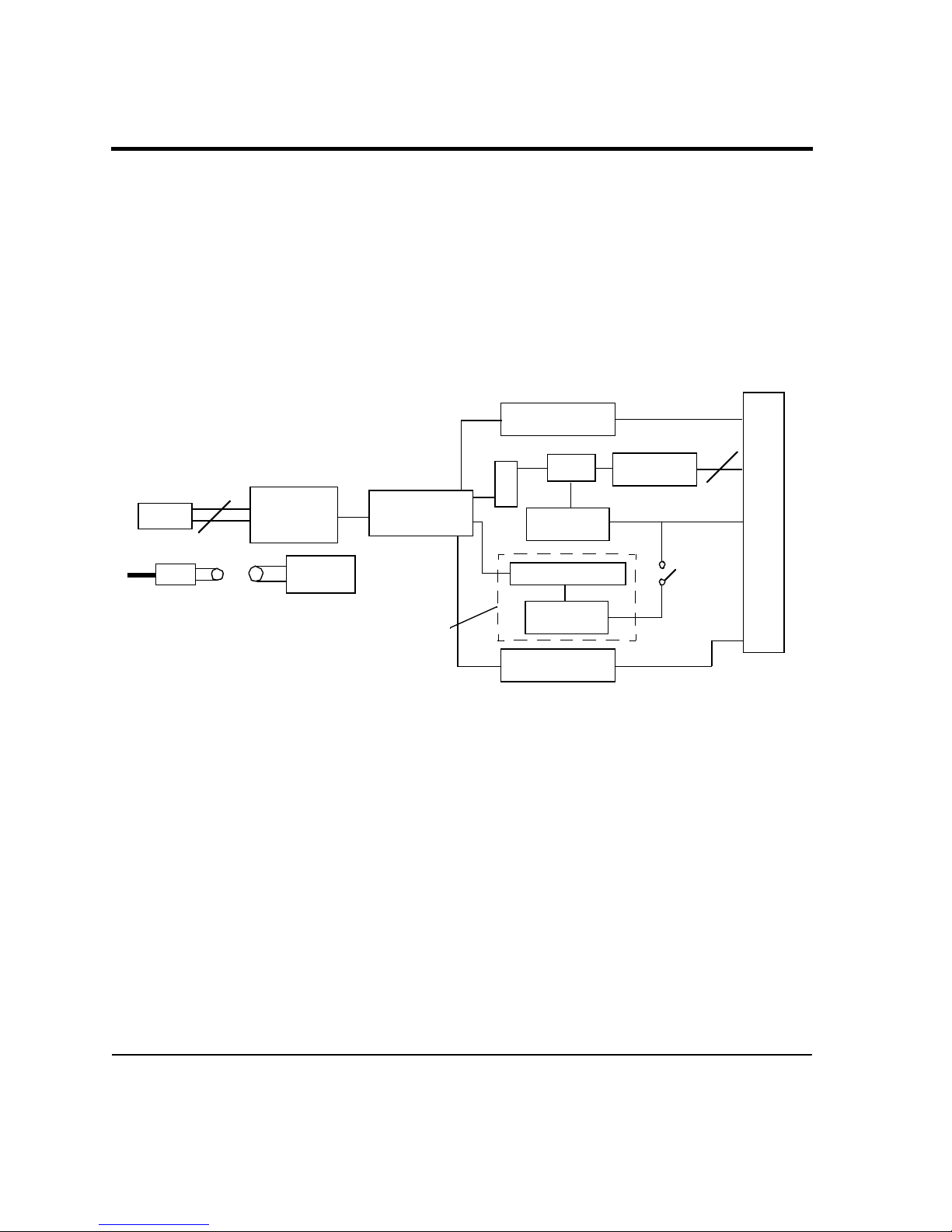
Features and basic specifications of the UDAS units are listed below. Specifications of each UDAS
unit are listed in Appendix A, Specifications. The UDAS system block diagram is shown below.
J2
DIGITAL I/O
4
USB
USB
INTERFACE
CHIP
POWER
SUPPLY
µ PROCESSOR
Dotted line indicates optional Analog Output
FIGURE 1.1 UDAS Series Block Diagram
SoftwareSupport LibrarySoftwareSupport Library
The software support library is included with the UDAS.
UDAS Support Software includes:
• UDAS SYSCHECK
• U-Link Software Libraries for Windows 98
• LabView 5.0 Support Library
• UDAS Device Driver
• Visual Designer Support Library
A/D
FIFO
RATE
GENERATOR
ANALOG OUTPUT
RATE
GENERATOR
COUNTER
ANALOG
16
FRONT-END
I/O CONNECTOR
1-2
Page 10

UDAS SYSCHECK
The SYSCHECK application enables you to verify the UDAS installation is functioning properly.
SYSCHECK can also be used during the calibration procedure and for simple data acquisition.
U-Link Software Libraries for Windows 98
These function libraries allow custom application development using C/C++ and Visual Basic.
LabView 5.0 Support Library
Allows the use of UDAS with LabVIEW.
UDAS Device Driver
To use the UDAS unit, Microsoft Windows requires the UDAS device driver.
Visual Designer Support Library
The Visual Designer Support Library allows the use of the UDAS device in Visual Designer 4.0
applications.
Analog InputAnalog Input
The UDAS unit features:
• 16 Single-ended or 8 Differential Analog Inputs
(±0.05 V, ±0.1 V, ±0.5 V, ±1 V, ±5 V, ±10 V, and 0-0.1 V, 0-1.0 V, 0-10V programmable input
ranges).
• Analog Input resolution: 12-bit (1 part in 4096).
• Up to 100 kHz input sample rate (built-in timebase generator).
• Analog Trigger function to start analog-to-digital conversions.
Analog OutputAnalog Output
The UDAS unit features:
• Up to 100 kHz output rate (built-in timebase generator).
• 2 analog outputs at 12-bit resolution (±10V output range, 1 part in 4096).
• Waveform generation
1-3
Page 11

UDAS-1001E Series Data Acquisition Systems
Digital Input/OutputDigital Input/Output
• 16 Programmable digital I/O channels. Groups of 8 separately programmable for input or
output.
• Digital inputs can be programmed to read digital signal status, detect a change-of-state or to
perform low speed event counting (up to 2 kHz).
• Digital outputs can drive TTL level signals.
• 8 of the 16 I/O channels can be configured for preset direction and output state levels for safe
power-up and reset situations.
CounterCounter
One 16-bit counter channel performs general purpose event counting and frequency measurement
up to 20 MHz up to 2 MHz for high-speed event counting.
TerminationTermination
The UDAS-1001E-3 and UDAS-1001E-4 units have built-in depluggable termination blocks for
connecting I/O signals. The UDAS-1001E-1 and UDAS-1001E-2 units have a 50-pin I/O connector
for attaching external termination. Information on termination panels is provided in Appendix B,
Accessories.
1.21.2 UDAS 1001E Series Functional DescriptionUDAS 1001E Series Functional Description
This section provides information on the following data acquisition functions:
• Analog input
• High-speed analog input
• Acquisition pacing and triggering
• Power supplied by the USB port or by an external power supply
1.2.11.2.1 Data Acquisition FunctionsData Acquisition Functions
Analog InputAnalog Input
The A/D converter on the UDAS device is a 12-bit converter with a throughput rate of 100 kHz.
For analog input:
• Programmable input voltage ranges are 0-10 V, ±5 V, and ±10 V.
1-4
Page 12

• Programmable gains are 1, 10, and 100 which translate to a full-scale input of 0-10 V, 0-1.0 V,
0-0.1 V, ±10 V, ±1.0 V, ±0.1 V, ±5 V, ±0.5 V, and ±0.05 V.
• The analog input section has 16 single-ended or 8-differential analog input channels.
The analog input section has a first-in-first-out (FIFO) buffer for high-speed capturing of data up
to 100 kHz.
An analog trigger is also provided to initiate high-speed conversions based on a voltage transition
on a selected analog input channel, or on an external TTL level signal. A programmable crystalbased rate generator regulates high-speed conversions.
High-Speed Analog Input ModeHigh-Speed Analog Input Mode
High-speed mode uses the rate generator (described below), or an external input to start data
conversions. The use of the rate generator or an external signal to start conversions is referred to
as pacing.
On the UDAS unit, the rate generator is able to provide rates from 0.477 conversions per second
to 100,000 conversions per second. These conversions are either performed on a single input
channel, or performed on a range of input channels by using the channel scanner (described
below).
When the conversion is complete on the current channel, the channel scanner automatically
selects the next channel. The term high-speed refers to the use of pacing to automatically begin
the conversions. The speed of the actual rate of conversions can be controlled by using the rate
generator. See Rate Generator , on page 1-6.
Starting and Stopping the High-Speed Analog Input ModeStarting and Stopping the High-Speed Analog Input Mode
There are several methods to start and stop conversions available on the UDAS:
• Start with trigger, Stop with software
• Start with trigger, Stop after N samples
• Start with software, Stop N samples after trigger
• Start with software, Stop with software
• Start with software, Stop after N samples
Starting Conversions
To start the conversions, use either a trigger or a software command. The trigger can be an
external digital TTL level input, or an analog input. For an external TTL signal, the slope (rising
edge or falling edge) must be specified. Use the external input pin to provide this input.
1-5
Page 13

UDAS-1001E Series Data Acquisition Systems
If an analog input is used for the trigger, specify the trigger level, analog input channel, and
slope. Use analog output channel 1 for setting the trigger level.
Note: When using analog input channel 1 for a trigger, do not use this channel
for any other purpose.
When an input signal on the selected channel of the proper slope (rising or falling voltage) crosses
the trigger level, the conversion process begins.
Stopping Conversions
To stop a conversion, use either a software command, an N samples counter, or a combination of a
trigger and an N samples counter.
Use the N samples counter to specify the number of samples that you want to capture.
When the trigger is used to stop a conversion, and the N samples counter is used, a post-
triggering function occurs. In this mode, software is used to start conversions and continue
indefinitely until a trigger event occurs. When a trigger event occurs, N additional samples are
captured.
Rate GeneratorRate Generator
The UDAS unit contains an on-board 24-bit rate generator for analog input pacing. The base clock
for the rate generator is an 8 MHz clock derived from a crystal which provides 125 ns resolution
and a frequency range of 0.4768371 Hz to 4 MHz.
The I/O connector has a rate generator output pin that is driven by either the Analog Input Rate
Generator or the Analog Output Rate Generator.
Channel ScannerChannel Scanner
When the channel scanner is enabled, immediately after the conversion on the current channel
finishes, the next analog input channel to be converted is automatically selected.
The UDAS device incorporates a 0 to N scanner. This allows analog conversions on all of the input
channels from channel 0 to channel N, where the value of N is programmable.
The scanner selects each channel for conversion, beginning with channel 0, incrementing to
channel N. After the conversion on channel N is complete, the scanner selects channel 0 and the
process repeats.
1-6
Page 14
The scanner operates with the built-in analog channels, or with the optional AI-MAX. The AIMAX allows up to 256 analog input channels to be connected to a single UDAS device.
Note: The scanner begins on the selected trigger channel and not channel 0 when the
start on trigger mode is used with an analog input trigger.
High-Speed Analog Input TriggeringHigh-Speed Analog Input Triggering
To start or stop conversions, use triggering in the High-Speed Analog Input mode in the UDAS
device. The trigger signal can be either an analog input or a digital input.
When using an analog input as the trigger, the start on trigger mode causes the scanner to start
on the trigger channel. For example, if the trigger channel is set to 5, the N channel of the 0 to N
scanner is set to 7, the return data is as follows:
channel 5
channel 6
channel 7
channel 0
channel 1
...
channel 7
channel 0
...
When using the stop on trigger mode and the trigger is from an analog input channel, the trigger
signal is sampled only when the trigger channel is the active scanner channel. Although this
allows any channel to be used for triggering, it imposes some restrictions on the characteristic of
the trigger signal.
The duration of the trigger signal must be long enough to cause the unit to trigger. Use the
following formula to calculate the length of a signal to ensure that the signal is long enough to
activate the trigger: (Total channels scanned)/(scan rate in Hz).
1-7
Page 15

UDAS-1001E Series Data Acquisition Systems
Example:
If 9 channels are being scanned at a rate of 100Hz and the slope is low to high, the trigger signal
must remain below the trigger level for 9/100 of a second, and above the trigger level for 9/100 of a
second to ensure that a trigger event occurs. When using External Input as the trigger, this
restriction does not apply.
When using an analog input channel for triggering, analog output channel 1 is used to set the
trigger level.
Note: Do not use analog output channel 1 for any other purpose while analog
triggering is in use.
Due to the internal configuration of the unit, the voltage appears on the analog output 1 pin as
the negative value of the desired trigger voltage. Connecting this pin to another signal, or
shorting it out causes the trigger voltage to be incorrect.
Auto ZeroAuto Zero
When in auto zero mode, the inputs to the Analog input circuit are internally grounded, disabling
the input multiplexers. This enables a known 0 volt signal to be measured, and the value read can
be used to compensate for input offset errors.
Analog OutputAnalog Output
The UDAS device has two analog output channels. Each output channel has 12-bit resolution and
a ±10 V output range. A FIFO is available for waveform generation.
This FIFO can be used as a circular buffer for either or both analog output channels to allow
repetitive waveform generation and supports waveforms of up to 512 points (single channel) or
256 points (dual channel). The unit also supports non-repetitive wave forms.
When the unit is powered-on and the analog outputs are not enabled, the output voltage is 0 V.
This provides a known voltage when the UDAS unit is powered-up.
Analog output channel 1 is also used to support the analog trigger function for hardware-paced
analog input conversions (as described above).
Digital I/ODigital I/O
The digital data acquisition circuit consists of two 8-bit digital I/O ports providing 16 digital I/O
bits and one 32-bit counter. Output power-on states are configured for Port 1 through an internal
DIP switch. The digital I/O is configured as 2 ports (0 and 1) of eight bits each.
1-8
Page 16

Digital I/O signals are TTL-compatible and perform functions such as reading digital inputs,
driving digital outputs, and detecting input change-of-state.
Digital I/O direction is programmable separately for each port through software. A nine-position
DIP switch is provided inside of the unit to select the power-up direction of Digital I/O Port 1
(input/output) and to individually set power-up output states for each bit.
CountersCounters
One counter input line is connected to a 32-bit counter for high-speed counting (up to 2 MHz).
This counter supports event counting and frequency measurement.
An event counter counts pulses occurring at its input. For frequency measurement mode, the
pulses are captured over an internally generated gate time. The frequency is calculated from the
captured count and the gate time. The gate time can be set to 1ms, 10ms, 100ms, or 1s through
software.
TerminationTermination
The UDAS unit provides the user with several options for connecting to I/O signals. You can use a
50-pin ribbon cable to connect signals directly to the UDAS unit.
There are many termination products available from Intelligent Instrumentation with a 50-pin
interface. See our catalog for a variety of termination options. For the UDAS-1001E-3 and UDAS1001E-4 models, use the built-in termination to connect signals directly to the unit.
The built-in termination panel is directly mounted to the back plate of the UDAS unit, providing
easy access to all I/O signals (FIGURE 1.2, UDAS-1001E-4 dimensional drawing). The
connections are made using pluggable 5mm terminal strips to simplify the wiring. A cold junction
compensation circuit (CJC) is incorporated on the board to allow the use of thermocouples.
To use the CJC circuit, you must enable it by setting the jumpers. The jumpers are located on the
back side of the termination panel and require removal of the panel to gain access. For
information on the jumpers, reference Chapter 2, Configuration and Installation, and see TABLE
2.1, CJC Jumper Positions.
Note: When the CJC is enabled, differential channel 0 is used. Do not connect
anything to Analog Input 0 or Analog Input 8.
1-9
Page 17
UDAS-1001E Series Data Acquisition Systems
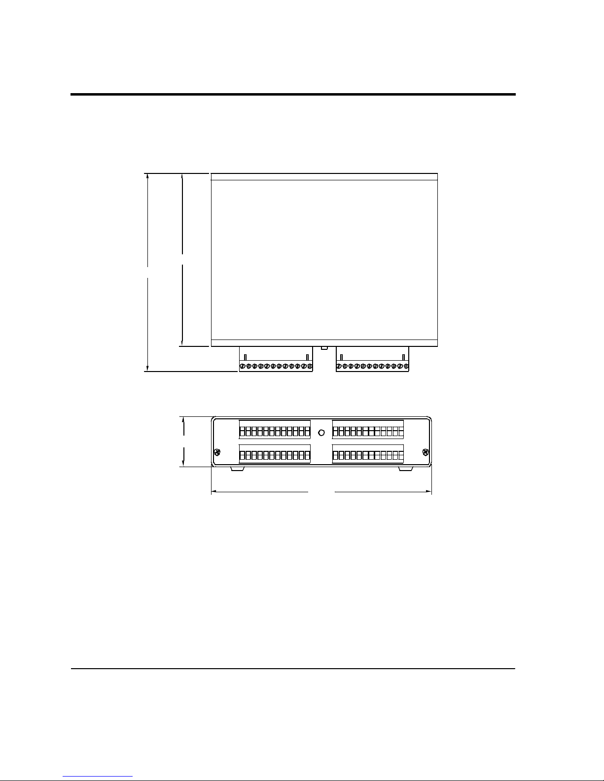
A diagram of the termination panel for the UDAS-1001E-4 unit is shown below.
5.750
6.600
1-10
1.520
7.290
FIGURE 1.2 UDAS-1001E-4 dimensional drawing
Page 18

1.2.21.2.2 PowerPower
The UDAS unit normally uses power from the host computer via the USB cable. Power can also be
obtained from an external power supply that is available (See Appendix B, Accessories). When the
UDAS unit is connected to a power source, the computer controls the power. The unit does not
have a power switch. There is an LED labeled PWR located on the front panel that indicates
power to the unit, regardless of its source.
The USB specification imposes strict requirements on power usage. If an external power supply is
used, up to 200 mA at +5 VDC is available to external termination circuits (available at pin-26
and pin-48 of the unit’s 50-pin I/O connector).
See section 1.3, Software Support and Accessories or Appendix B, Accessories for the part numbers
of the available Power Adapters. If the power is supplied from the PC through the USB port, care
must be taken to limit the load from the external termination panel to less than 20 mA.
1.31.3 Software Support and AccessoriesSoftware Support and Accessories
1.3.11.3.1 Software SupportSoftware Support
DiagnosticDiagnostic
UDAS SYSCHECK
UDAS SYSCHECK software for Windows is an easy-to-use system assurance and diagnostic
utility package. UDAS SYSCHECK is a useful tool for quickly verifying the hardware is
functioning properly. This program also performs basic data acquisition tasks. UDAS
SYSCHECK is provided on the UDAS-1001E Data Acquisition System CD, or is available to
download, free of charge, from Intelligent Instrumentation’s Web site (www.instrument.com).
DevelopmentDevelopment
Visual Designer Application Generator
Visual Designer is a powerful, easy-to-use application generator that supports all of Intelligent
Instrumentation’s data acquisition hardware and is available from Intelligent Instrumentation.
Use Visual Designer to develop custom Windows applications for collecting remote data using a
graphical block diagram development environment.
To create custom applications in a fraction of the time it takes when using a programming
language, Visual Designer is able to combine built-in professional screen displays and user
interface elements with powerful data acquisition and processing blocks.
1-11
Page 19

UDAS-1001E Series Data Acquisition Systems
Visual Designer UDAS Support Library
This support package provides the block functions necessary to acquire data and output data
using the UDAS device. To use Visual Designer or the Visual Designer Evaluation Version with
an UDAS unit, the Visual Designer UDAS Support Library must be installed on the computer.
LabVIEW UDAS Support Library
This support package enables the development of customized UDAS data acquisition and control
applications under the LabVIEW environment. To use this software, National Instruments
LabVIEW software (version 5.0 or higher is supported) must be installed on the computer.
1-12
Page 20

Chapter 2Chapter 2 Configuration and Configuration and
InstallationInstallation
2.12.1 IntroductionIntroduction
This chapter contains instructions on the configuration and installation of the UDAS unit.
2.22.2 Power-on Default Digital I/O ConfigurationPower-on Default Digital I/O Configuration
In some situations, it is important to have the digital output port on a UDAS unit initialize at
power-on to a particular state. For example, if the digital output port controls a piece of
mechanical equipment, safety regulations may require the digital output port bits to have values
of 0000 0011 when power is first applied. Port 1 on the UDAS unit provides the ability to set the
power-on direction to output and the states of all of the bits. A switch block located on the main
board of the UDAS unit accomplishes this task. Since the default switch states configure the port
for input, you may not need to change the switch settings.
This section contains instructions for setting the power-on default Digital I/O configuration, if
applicable.
CAUTION:
Use proper static-sensitive device handling procedures (such as the use of grounded
wrist-strap) when opening the unit, as damage to the equipment may occur.
Removing the CoverRemoving the Cover
1. Unplug the power supply to the UDAS unit.
2. Using a Phillips head screwdriver, remove the two Phillips head screws on the front face plate
of the UDAS unit I/O cover. The front face plate contains the power and status indicators and
the USB connector.
3. Carefully separate the face plate from the cover.
4. Slide the cover towards the open end of the unit to free it from the back termination plate,
removing the cover from the UDAS unit.
2-1
Page 21

Configuration and Installation
Setting the ConfigurationSetting the Configuration
Switches 1-8 set the initial levels of the port’s channels 0-7 if the port is set for output operation.
A switch set to the On position sets the corresponding port’s output channel to a high level (TTL
+5V) on power-up.
H4 H4
2-2
00 00 0 0
S1
FIGURE 2.1 UDAS Switch S1
Page 22

If you plan to use any of the digital I/O ports for output control in your application(s), note the
following Caution statement:
CAUTION:
For applications using UDAS units to generate output signals for control or other
sensitive purposes, the status or level of outputs during power-up may be of critical
importance. Integrated circuits and other devices powered by supply voltages are
subject to possible transients or an indeterminate status while the power supply
voltages are making the transition from zero to their steady-state values.
Locate switch S1 shown in FIGURE 2.1, UDAS Switch S1 in the lower left-hand corner of the
board.
1. Set the direction for Port 1. The default setting is input (Off).
To designate Port 1 as an output port: set switch 9 to the On position.
To designate Port 1 as an input port: set switch 9 to the Off position.
2. To set the initial data for Port 1, set switches 1-8.
On = 5 V
Off = 0 V
Note: You can reconfigure any of the ports through software after the unit is
powered-up. Port 0 always powers-up as an input port.
Reinstalling the CoverReinstalling the Cover
1. Insert the cover onto the rails located on both sides of the base of the UDAS unit and slide the
cover towards the back panel until the cover is seated into the frame on the back panel.
2. Place the face plate over the edges of the cover and unit’s frame.
3. Align the screw holes on the cover with the unit, insert each Phillips screw on the face plate
and tighten the screws into place.
Enabling the CJCEnabling the CJC
To enable the CJC:
• Install jumpers A, C and D on JP1.
The CJC circuit uses differential channel 0 to report compensation information to the UDAS.
When using the CJC circuit, verify there is no external signal connected to channel 0/8.
2-3
Page 23

Configuration and Installation
Channels connected to a thermocouple must be connected to bias resistors for proper operation.
Use jumpers JP2 and JP3.
Note: When monitoring thermocouples, always use differential channels.
To select the jumpers for each channel that you plan to use for thermocouples, use TABLE 2.1,
CJC Jumper Positions shown below.
Differential JP1 Jumper Position JP2 Jumper Position
Channel #
1 AI 1 AI 9
2 AI 2 AI 10
3 AI 3 AI 11
4 AI 4 AI 12
2-4
5 AI 5 AI 13
6 AI 6 AI 14
7 AI 7 AI 15
TABLE 2.1 CJC Jumper Positions
Page 24

2.32.3 Connecting the UDAS UnitConnecting the UDAS Unit
Making the Initial ConnectionMaking the Initial Connection
1. With the computer powered up, connect the USB cable to the computer or hub.
2. Connect the other end of the USB cable to the UDAS unit.
3. Verify the red PWR LED located on the face plate of the UDAS unit illuminates.
4. The system builds a driver information database, and then the Add New Hardware Wizard
dialog appears on the computer monitor. The wizard searches for new drivers for the unknown
device. Click the Next button.
5. Select Search for the best driver, and click the Next button.
6. Insert the UDAS-1001E Data Acquisition System CD in the computer’s CD ROM drive.
7. In the Add New Hardware Wizard dialog, select the CD-ROM drive by clicking on the check
box. Deselect the check boxes for the Floppy Disk drive (default setting), Microsoft Windows
Update , and Specify Location Options. Click Next to continue.
8. The Wizard finds the TAOSDRV.INF file and displays a message stating the file has been
found. Click the Next button.
The Wizard copies the driver and rebuilds the driver database.
9. After the installation process is complete, click the Finish button.
The unit’s driver is now installed.
10. Verify the red STATUS LED located on the face plate of the UDAS unit is illuminated.
11. Verify the system is operating correctly using the UDAS SYSCHECK software. UDAS
SYSCHECK software is included on the UDAS-1001E Data Acquisition System CD and can
also be found on Intelligent Instrumentation’s web site. See Section 1.3.1, Software
Support, on page1-11 in Chapter 1, UDAS-1001E Series Data Acquisition Systems.
12. For information on using SYSCHECK, see Chapter 3, Checking the System in this manual.
2-5
Page 25

Chapter 3Chapter 3 Checking the SystemChecking the System
3.13.1 IntroductionIntroduction
This chapter contains instructions for installing and using the UDAS SYSCHECK software. The
software contains diagnostic features that verify the UDAS unit is functioning.
WARNING!
Use extreme caution when using SYSCHECK.
The UDAS SYSCHECK software could cause unexpected results in the equipment that you
connect to the UDAS unit.
Depending on the type of equipment that you have connected to the UDAS unit, severe
damage to equipment and/or bodily harm may occur while conditions of the UDAS are in
transition.
Large unisolated voltages may damage the UDAS unit. UDAS analog output will not drive low
impedance loads.
The UDAS digital I/O inputs and outputs must be TTL compliant.
UDAS analog inputs in excess of 20 V may cause permanent damage to the UDAS unit.
UDAS counter inputs must be TTL compliant.
SYSCHECK is only an interface to the UDAS unit(s). The way that you interface input or outputs
to the UDAS can be a complicated issue.
Since a variety of termination panels are available for the UDAS units, refer to the
documentation provided with the termination panel for the exact I/O configuration of the specific
panel that you purchased.
Termination options are discussed in Appendix B, Accessories in this manual.
3-1
Page 26

Checking the System
3.23.2 Installing and Running UDAS SYSCHECKInstalling and Running UDAS SYSCHECK
UDAS SYSCHECK provides an easy-to-use graphical interface for using and displaying the I/O
capabilities of the UDAS unit.
System RequirementsSystem Requirements
• UDAS SYSCHECK 1.0 only runs on Windows 98.
• The installation requires approximately 1 Mbyte of free disk space.
Installing SYSCHECKInstalling SYSCHECK
1. To install UDAS SYSCHECK, insert the UDAS-1001E Data Acquisition System CD into the
CD ROM drive on the computer.
2. From the Windows 98 desktop, click Start, select Run and type:
<Use your CD drive letter>:\Syscheck\SETUP.EXE<ENTER>
3. Follow the software installation instructions in the dialogs (to stop the installation press ESC
or click Cancel).
When the installation is complete, UDAS SYSYCHECK files are copied to a newly created
folder on the computer’s hard drive. A new folder with shortcuts to the UDAS SYSCHECK
program appears on the Start menu.
3.33.3 SYSCHECK OperationSYSCHECK Operation
When SYSCHECK runs, it queries the Universal Serial Bus (USB) to locate all of the UDAS units
that are attached to the host. UDAS SYSCHECK reports the number of UDAS units detected and
tracks the UDAS units by a unique serial number assigned to each unit. The serial number is
provided on the outside of the unit, and internally in the UDAS unit’s firmware.
In the UDAS SYSCHECK window, the main menu contains three selection tabs, Unit Info,
System Check, and Paced Analog Input as shown in FIGURE 3.1, Unit Info dialog.
In the Unit Info dialog, select one UDAS unit from the drop-down list. After making your
selection, other features of the software allow you to display inputs to, or manipulate outputs
from, the selected UDAS unit.
3-2
Page 27

3.3.1 Unit Info
The Unit Info dialog displays the number of UDAS units detected and has a drop down list
containing the serial number for each UDAS unit detected by SYSCHECK.
FIGURE 3.1 Unit Info dialog
If there is only one UDAS unit, the message shown beneath the drop down list displays the unit
type and self-test results. When the self-test reads PASSED, the unit is operable.
If multiple UDAS units are being used, to select a unit for testing, click the desired serial number
in the list.This selection process updates the description and the self-test results to reflect the
state of the currently selected unit.
After you select a unit’s serial number from the list, the SYSCHECK and paced analog input
operations are performed on the selected unit.
3-3
Page 28

Checking the System
3.3.2 System Check
When the System Check tab is selected, a dialog containing buttons used to execute a variety of
system test programs appears as shown in FIGURE 3.2, UDAS SYSCHECK System Check dialog.
FIGURE 3.2 UDAS SYSCHECK System Check dialog
The System Check tabbed dialog displays four major sub-functions possible on the UDAS units.
These include Analog Input, Analog Output, Counter, and Digital Input/Output. Click one of
these buttons to open a dialog to manipulate and/or display the desired sub-function on the
selected UDAS unit.
To test each of the I/O types listed in the dialog, click the corresponding button to launch a new
window for testing that I/O type on the UDAS unit. Examples of each I/O test are provided in the
next two sections.
3-4
Page 29

3.3.2.13.3.2.1 Analog Input TestAnalog Input Test
Click the Analog In button to access a new window specific to analog input. The UDAS
SYSCHECK ANALOG INPUT dialog shown in FIGURE 3.3, UDAS SYSCHECK Analog Input
Test of a UDAS unit appears.
The analog input test performs software-based reading of the first 8 analog input channels on
UDAS units.
Select from the drop-down lists to select the Range, Gain, Single Ended/Differential configuration,
and Average (the number of readings to average from each channel).
Select either the Volts or Counts radio button to display the channel data in volts or counts.
Click the Read Channels button to acquire the input voltages to the UDAS unit. Each time that
you click the Read Channels button, the channel data is read by the UDAS unit and the display is
updated.
FIGURE 3.3 UDAS SYSCHECK Analog Input Test of a UDAS unit
3-5
Page 30

Checking the System
3.3.2.23.3.2.2 Analog Output TestAnalog Output Test
The analog output test controls the voltage on the analog output channels of the UDAS unit.
In the UDAS SYSCHECK Test Category Selection Window, click the Analog Out button and the
UDAS SYSCHECK ANALOG OUTPUT dialog shown in FIGURE 3.4, UDAS SYSCHECK Analog
Output Test of a UDAS unit opens.
In the Channel 0 and Channel 1 fields, click to insert the cursor and enter the desired value (volts
or counts) in any of the four data entry fields.
After replacing the old value with a new value, press the Enter key to update both analog outputs
from the UDAS unit.
Clicking the Disable Outputs check box grounds both of the analog output channels.
FIGURE 3.4 UDAS SYSCHECK Analog Output Test of a UDAS unit
3-6
Page 31

3.3.2.33.3.2.3 Counter TestCounter Test
The counter test monitors TTL transitions that are connected to the counter input of the UDAS
unit. Depending on the mode that you select, the TTL level of the gate pin may effect the readings.
For all of the modes except Measure frequency, data is automatically read and displayed four
times per second.
For the Measure frequency mode, the rate of display updates may be slower depending on the
gate time selection.
Checking the Reset counts every display check box causes the counter to reset to zero after every
read and display cycle. The interface is shown in FIGURE 3.5, UDAS SYSCHECK Counter Test in
Count Mode.
FIGURE 3.5 UDAS SYSCHECK Counter Test in Count Mode
3-7
Page 32

Checking the System
For the Count when gate is high and the Count when gate is low modes, the TTL level of the gate
enables or disables counting, depending on the mode that you set. If there is no input connected to
the gate input, use the Count when the gate is in high mode.
For the modes Measure input high period, Measure input low period, and Measure total period,
the data displays shown at the bottom portion of the dialog provide the status and the time
between the most recent appropriate edges as shown in FIGURE 3.6, UDAS SYSCHECK Counter
Test: Measure Input High Mode.
FIGURE 3.6 UDAS SYSCHECK Counter Test: Measure Input High Mode
The status field is looking for TTL transitions.
Select the Measure frequency radio button and the dialog shown in FIGURE 3.7, UDAS
SYSCHECK Counter Test: Measure Frequency Mode opens.
3-8
Page 33

Select the desired Gate Time. The data displays shown at the lower portion of the dialog provide
the status and the frequency in hertz.
FIGURE 3.7 UDAS SYSCHECK Counter Test: Measure Frequency Mode
The gate time is the amount of time that UDAS uses to count TTL transitions. This time base
allows frequency to be calculated by the software.
Longer gate times result in frequency calculations with more significant digits because a greater
number of transitions are gathered. Shorter gate times result in frequency calculations with
fewer significant digits because a smaller number of transitions are gathered.
3-9
Page 34

Checking the System
Digital I/O TestDigital I/O Test
The Digital Input/Output test enables you to read data from, or write data to, either 8-bit Digital
I/O port on a UDAS unit. FIGURE 3.8, UDAS SYSCHECK Digital I/O Test shows an example
test of the UDAS unit that has two 8-bit digital I/O ports.
FIGURE 3.8 UDAS SYSCHECK Digital I/O Test
Use the Input and Output radio buttons to select the direction of a port.
The input and output data is displayed in Hexadecimal (0-FF).
Input ports are read and displayed four times per second.
Output data is written to the port only after clicking the Write Output Data button.
3-10
Page 35

3.3.3 Paced Analog Input
The Paced Analog Input dialog enables you to configure a hardware-paced analog input process.
Select the number of channels to include in the data run, select the gain, and select the single-
ended/differential from drop-down lists in each field. See FIGURE 3.9, UDAS SYSCHECK Paced
Analog Input Window .
FIGURE 3.9 UDAS SYSCHECK Paced Analog Input Window
The pacer rate controls the clock rate of an on-board clock generator.
This clock can be configured for frequencies from 1 to 100,000 hertz. The pacer rate and number of
channels determine the sample rate for each channel in the run.
3-11
Page 36

Checking the System
Clicking the High-Speed Run button (shown in FIGURE 3.9, UDAS SYSCHECK Paced Analog
Input Window ) configures and starts the process. This launches a full screen window that
displays the results of the run.
FIGURE 3.10 High-Speed Aquisition Sample
The time base is displayed on the x-axis and the voltages are displayed on the y-axis. A sample
screen is shown in FIGURE 3.10, High-Speed Aquisition Sample. Slow pacer rates may have slow
screen update rates.
3-12
Page 37

3.43.4 Troubleshooting TipsTroubleshooting Tips
3.4.1 Basic Troubleshooting
If you are unable to successfully communicate with the UDAS unit, this section contains
troubleshooting hints which may help identify the problem.
Verify that all of the proper connections have been made between the computer, UDAS unit(s),
and the equipment being monitored. If running SYSCHECK displays a message on the computer
monitor in a pop-up window as shown in FIGURE 3.11, System Error message window, reference
section 3.4.1.1, Verify Lower Level Drivers.
FIGURE 3.11 System Error message window
3.4.1.13.4.1.1 Verify Lower Level DriversVerify Lower Level Drivers
To verify that low-level drivers are functional, check the USB port, UDAS driver, and power.
USB PortUSB Port
Verify the system has a USB port that is properly installed from the Windows’ Start menu by
following these steps:
1. From the Start button, click Settings, then click Control Panel.
2. Double-click on the System icon.
3. Click the Device Manager tab.
4. Click the View devices by type radio button.
If you do not see the Universal serial bus controller, resolve the problem with the USB port before
continuing.
3-13
Page 38

Checking the System
UDAS DriversUDAS Drivers
Verify the UDAS system driver is properly installed by following the instructions for the USB
Port (above).
Click on the plus sign (+) located next to the Universal serial bus controller. When the directory
opens, double-click III Taos USB Data Acquisition System. A pop-up window appears displaying a
message that reads, This device is working properly.
If the III Taos USB Data Acquisition System icon does not appear in the USB devices list, verify
that both of the LEDs located on the front panel of the UDAS unit are illuminated. Verify that
your external equipment is not consuming excessive power. Refer to the power test in the next
section.
Power TestPower Test
For proper operation, the power test requires:
• the UDAS device be powered.
• the UDAS device be connected to the USB.
• the UDAS device pass its power on self-test (POST).
• the UDAS device be initialized by the host computer.
To perform the power test:
1. Unplug the USB cable from the UDAS port.
2. Plug the USB unit cable back into the UDAS port.
• One LED illuminates immediately, indicating power.
• The computer monitor may display the Busy hourglass icon while the UDAS unit
initializes.
• The UDAS status LED illuminates after POST and host enumeration.
3. Verify the UDAS unit has two LEDs illuminated.
Troubleshooting Errors
If the two LEDs do not illuminate:
• Disconnect the I/O signals from the unit.
• Unplug the unit for several seconds then reconnect the unit to see if the LEDs illuminate.
Some built-in tests may fail if the board was incompletely reset, even for components that are
functioning normally.
• Verify the unit is receiving power and the power LED is illuminated.
3-14
Page 39

• Check the wiring and cables for shorts or damage.
Note: For units with USB cables connected directly to the computer as a power
source, when the computer’s power is off or if the computer is in a suspended
mode, the UDAS unit shuts down.
If errors still persist after repeatedly checking the unit, check the technical support links on
Intelligent Instrumentation’s web site http://www.instrument.com for the most current support
information and contact addresses.
3-15
Page 40

Appendix AAppendix A SpecificationsSpecifications
A.1A.1 UDAS-1001E Series Hardware SpecificationsUDAS-1001E Series Hardware Specifications
All specifications are typical at 25ºC unless otherwise noted.
Note: When powered from an external source, the on-board power supply circuit can
supply up to 200mA at 5V DC to termination panels through the 50-pin I/O connector.
PARAMETER CONDITIONS SPECIFICATION
Analog Inputs
Number of Channels Single-ended 16
Differential 8
Resolution 12-bits (1 part in 4096)
Voltage Ranges 0 - 10 V, ±10 V, ±5 V
Overvoltage Protection Power on or off ±20 V
Software Programmable
Gains
Gain Accuracy Gain = 1 0.02%
Gain = 10 0.05%
Gain = 100 0.08%
Input Offset Voltage 3mV
Input Bias Current 500 pA
Input Impedence
Common Mode Input
Range
Common Mode Rejection 60 Hz, 100 ohm imbalance
Gain = 1 -85dB
Gain >= 10 -90dB
TABLE A.1 Hardware Specifications
1, 10, 100
+
9
10
ohms/50 pF
±10 V
A-1
Page 41

Specifications
PARAMETER CONDITIONS SPECIFICATION
Noise Input grounded at connector
(RMS)
Gain <=10 1.0 LSB
Gain = 100 1.2
DC Accuracy No missing codes, guaranteed
Linearity Error ±0.024%FS (± 1LSB)
Throughput 100 k Samples/second
Analog Trigger (with AO
option)
Range ±10 V
Hysterisis 28 mV
Resolution 4.88 mV nominal
Slope Pos/Neg
Analog Outputs (Optional)
Number of Channels 2
Resolution 12 bits (1 part in 4096)
Voltage Ranges ±10 V
Throughput 100 k Samples/second
Digital I/O
Number of Ports 8 channels (bits) per port 2
Input Levels TTL-compatible
Input Current High Level / Low Level 23 µA/1 µA
Output Levels TTL-compatible
Source/Sink Vout = High/Low 15mA / 12mA
High-Speed Counter
TABLE A.1 Hardware Specifications (Continued)
A-2
Page 42

PARAMETER CONDITIONS SPECIFICATION
Resolution 32-Bit
Number of Channels 1
Max Input frequency TTL-level input 2 MHz
TimeBase Generator
Type Crystal-based Rate Generator (24-Bit)
Number 2 (1 analog input, 1 analog output)
Resolution 125 ns
Output Frequency Range 0.5 Hz to 1 Mhz
Output Levels TTL-compatible
Bus Interface
Type USB
Power
Voltage Range USB or External +5 V
Current Available (*1) +5 V 200 mA maximum
Current Requirements USB powered <500 mA
Physical Characteristics
Size 5.75" D x 7.25" W x 1.60" H
Operating Temperature
Range
All Specifications are typical at 25 C unless otherwise noted. Note (*1): When powered from an
external source, the on-board power supply circuit can supply up to 200mA at 5VDC to
termination panels through the 50-pin I/O connector.
TABLE A.1 Hardware Specifications (Continued)
(approximately)
14.61 cm D x 18.42 cm W x 4.06
cm H
0 - 50 C
A-3
Page 43

Specifications
A.2A.2 UDAS-1001E-3, UDAS-1001E-4 DimensionsUDAS-1001E-3, UDAS-1001E-4 Dimensions
UDAS units are housed in standard metal enclosures made of a rugged extruded aluminum base
(connected to chassis ground) with a vinyl-clad steel cover. Interior tracks on side rails hold the
circuit board securely in place. This page provides the dimensions of each unit with the
connectors.
5.750
6.600
A-4
FIGURE A.1 Dimensions of the UDAS unit (Top view)
1.520
7.290
FIGURE A.2 Dimensions of the UDAS unit (Rear panel)
Page 44

4.700
.525
1.295
4.700
4-40 FH SCREW
4 PL
FIGURE A.3 Dimensions of the UDAS unit (Bottom view)
A-5
Page 45

Specifications
6-32 HEX STANDOFF
The dimensions of the UDAS PC board are shown below in FIGURE A.4 Dimensional Drawing of
the UDAS series PCB.
5.305
4.70
A-6
0.21
0.60
0.15
1.16 4.70
7.02
MAXIMUM COMPONENT HEIGHT
FIGURE A.4 Dimensional Drawing of the UDAS series PCB
TYP, 4 PL
Page 46

A.3A.3 UDAS I/O ConnectorsUDAS I/O Connectors
Signal Name Pin Single Ended Input Function Differential Input
Function
AI0 1 Analog Input Channel 0 Analog Input Channel 0+
AI1 5 Analog Input Channel 1 Analog Input Channel 1+
AI2 7 Analog Input Channel 2 Analog Input Channel 2+
AI3 11 Analog Input Channel 3 Analog Input Channel 3+
AI4 13 Analog Input Channel 4 Analog Input Channel 4+
AI5 17 Analog Input Channel 5 Analog Input Channel 5+
AI6 19 Analog Input Channel 6 Analog Input Channel 6+
AI7 23 Analog Input Channel 7 Analog Input Channel 7+
AI8 2 Analog Input Channel 8 Analog Input Channel 0AI9 4 Analog Input Channel 9 Analog Input Channel 1AI10 8 Analog Input Channel 10 Analog Input Channel 2AI11 10 Analog Input Channel 11 Analog Input Channel 3AI12 14 Analog Input Channel 12 Analog Input Channel 4AI13 16 Analog Input Channel 13 Analog Input Channel 5AI14 20 Analog Input Channel 14 Analog Input Channel 6AI15 22 Analog Input Channel 15 Analog Input Channel 7-
Analog Ground 3 Analog Ground **
Analog Ground 6 Analog Ground **
Analog Ground 9 Analog Ground **
Analog Ground 15 Analog Ground **
Analog Ground 18 Analog Ground **
Analog Ground 24 Analog Ground **
+5V 26 5V Supply **
+5V 48 5V Supply **
TABLE A.2 UDAS I/O Connectors
A-7
Page 47

Specifications
Signal Name Pin Single Ended Input Function Differential Input
Function
AO 0 21 Analog Output Channel 0 **
AO 1 21 Digital I/O bit **
Digital Port 0 bit 0 27 Digital I/O bit **
Digital Port 0 bit 1 28 Digital I/O bit **
Digital Port 0 bit 2 29 Digital I/O bit **
Digital Port 0 bit 3 30 Digital I/O bit **
Digital Port 0 bit 4 31 Digital I/O bit **
Digital Port 0 bit 5 32 Digital I/O bit **
Digital Port 0 bit 6 33 Digital I/O bit **
Digital Port 0 bit 7 34 Digital I/O bit **
Digital Port 1 bit 0 35 Digital I/O bit **
Digital Port 1 bit 1 36 Digital I/O bit **
Digital Port 1 bit 2 37 Digital I/O bit **
Digital Port 1 bit 3 38 Digital I/O bit **
Digital Port 1 bit 4 39 Digital I/O bit **
Digital Port 1 bit 5 40 Digital I/O bit **
Digital Port 1 bit 6 41 Digital I/O bit **
Digital Port 1 bit 7 42 Digital I/O bit **
Counter Clock 43 Counter input **
Counter Gate 44 Counter gate input **
Rate Generator
Out
46 Analog In or Analog Out
(selectable) Rate Generator
output
TABLE A.2 UDAS I/O Connectors (Continued)
A-8
**
Page 48

Signal Name Pin Single Ended Input Function Differential Input
Function
External Input 47 External Trigger or Pacer input **
Digital Ground 49 Ground **
Digital Ground 50 Ground **
Unused 12 **
Unused 45 **
TABLE A.2 UDAS I/O Connectors (Continued)
A-9
Page 49

Appendix BAppendix B AccessoriesAccessories
This appendix includes information on the termination and mounting accessories that are
available separately from Intelligent Instrumentation for the UDAS unit.
TABLE B.1, Accessories for the UDAS-1001E Series provides the model numbers for the UDAS
units, the cables, and the power adpaters.
UDAS Model # Description
UDAS-1001-E-1 Multi-function USB data acquisition system.
UDAS-1001-E-2 Multi-function USB data acquisition system, with Analog Outputs.
UDAS-1001E-3 Multi-function USB data acquisition system, with built-in Termina-
tion.
UDAS-1001E-4 Multi-function USB data acquisition system, with built-in Termina-
tion and Analog Outputs.
OEM Versions (Board Only)
UDAS-1001E-1G Multi-function USB data acquisition system.
UDAS-1001E-2G Multi-function USB data acquisition system, with Analog Outputs.
Cables
50-pin to standard cables Cables used to connect the UDAS unit to the termination panel at
your equipment.
USB cable Connects the UDAS unit to the computer.
UDAS Power Adapters
UDAS-1006A-1 5 V DC (110 VAC input)
UDAS-1006A-2 5 V DC (230 VAC input)
TABLE B.1 Accessories for the UDAS-1001E Series
B-1
Page 50

Accessories
B.1B.1 UDAS Termination PanelsUDAS Termination Panels
The Termination Panel plugs directly into the I/O connectors of the UDAS unit, providing 32
channels of digital I/O through four screw-type terminal strips. Stand-off nuts on the UDAS unit
secure the termination panel in place.
B.1.1B.1.1 PCI-20429T-1 MultifunctionPCI-20429T-1 Multifunction Termination Panel Termination Panel
This termination panel plugs directly into the 50-pin I/O connector of the UDAS unit. Screw
terminals are provided on the panel to interface all analog and digital I/O lines with external
signals or devices. The PCI-20429T-1 secures to the UDAS unit’s back panel using the mounting
screws provided.
PCI-20429T-1
FIGURE B.1 Securing the PCI-20429T-1 to the UDAS unit
Access to all signals on the 50-pin I/O connector, except for +5 V, is provided through four 12position terminal blocks. Two of these terminal blocks are used for analog input and output
connections while the other two are used for digital I/O, counter, rate generator out and external
input connections. Screw terminals enable signal wires to be securely fastened to the terminal
blocks.
B-2
Page 51

FIGURE B.2, PCI-20429T-1 Multifunction Termination Panel shows the signals assigned to each
terminal block on this panel.
PORT 0: Bit 0 is also high-
speed counter input.
DI0
DI1
PORT 0
PORT 1
PORTs 0 and 1 on the UDAS-1001 -E can be independently
configured for input or output.
The CTRCLK, CTRGATE, and CTROUT terminations are not
used (N/C) on the EDAS-1002 -E.
FIGURE B.2 PCI-20429T-1 Multifunction Termination Panel
DI2
DI3
DGND
DO0
DO1
DO2
DO3
DGND
AIRG
EXTIN
DI4
DI5
DI6
DI7
DGND
DO4
D05
DO6
DO7
CTRCLK
CTRGATE
CTROUT
AGND
AI8
AI9
AI10
AI11
AGND
AI12
AI13
AI14
AI15
AGND
AO1
AGND
AI0
AI1
AI2
AI3
AGND
AI4
AI5
AI6
AI7
AGND
AO0
B-3
Page 52

Accessories
ANALOG TERMINATIONS:
B.1.2B.1.2 UDAS Termination and Signal Conditioning Options UDAS Termination and Signal Conditioning Options
FIGURE B.3, UDAS-1001E Termination Options uses the various UDAS-compatible termination
panels currently available from Intelligent Instrumentation. Also reference FIGURE B.4, UDAS-
1001E Termination Options (continued).
The EDAS-1010T-1 Analog I/O Termination Panels and EDAS-1011T-1 Digital I/O Termination
Panels are designed for ease-of-use with UDAS units.
The PCI-20430A-1 Adapter (available separately) and appropriate cables permit the UDAS unit
to be used with a wide variety of termination products.
FIGURE B.5, Diagram of the PCI-20430A-1’s connectors and cables shows a diagram of the PCI-
20430A-1’s connectors and compatible cables.
EDAS-1012A-1, -2
Standard-Density
50 -pin Unshielded
TO UDAS-1001E
I/O CONNECTOR
Analog/Digital Cable
DIGITAL TERMINATIONS:
Quick Disconnect Screw Terminal
Connections
EDAS-1013A-1, -2
Standard-Density
34-pin Unshielded
Digital Cable
Quick Disconnect Screw Terminal Connections
EDAS-1012A-3
4 in. interconnect
Analog/Digital Cable
Connect to 34-pin expansion
connector on any of the
above panels
EDAS-1013A-3
4 in. interconnect
Digital Cable
EDAS-1010T -1
Analog I/O Panels
Cascadable, DIN-Rail Mountable
8 Channels per panel for use
5B Series Signal Conditioning
Isolator blocks, or direct connection.
I/O types can be mixed
EDAS-1011T -1
Digital I/O Panels
Cascadable, DIN-Rail Mountable
8 Channels per panel for use
with 1100 Series Digital I/O
Opto-Isolator blocks, or direct
connection. I/O types can be mixed
FIGURE B.3 UDAS-1001E Termination Options
B-4
Page 53

PCI-20305T-1
Digital I/O Customizer Termination Panel
16 Channels
To UDAS unit
I/O Connectors
EDAS-1004T -1
PCI-20311A-1
Standard-Density
Digital Cable
PCI-20013A-1
Standard-Density
Ground Plane
Digital Cable
PCI-20036A-1
Standard-Density
Unshielded
Digital Cable
EDAS-1013A-1, -2
Standard-Density
Unshielded
Digital Cable
Shielded
or
PCI-20061A-1
Standard-Density
Shielded
Digital Cable
Screw Terminal Connections
Screw Terminal Connections
Screw Terminal Connections
Screw Terminal Connections
PCI-20324T-1
Opto-Isolated Digital I/O Panel
8 Channels for use with 1100 Series
Digital Opto -Isolator blocks
PCI-20326T-1
Opto-Isolated Digital I/O Expander Panel
8 Extra Channels for use with 1100 Series
Digital Opto -Isolator blocks
PCI-20355T-1
Relay Output Panel
16 Outputs
PCI -20361T-1
Opto-Isolated Digital Input Panel
16 Inputs
PCI-20018T
Digital Optical Isolation I/O Panel
8 Channels for use with 1100 Series
Digital Opto-Isolator blocks
PCI-20048T
Digital Optical Isolation I/O Panel
PCI-20025T-2
Digital I/O Customizer Panel
Up to 32 Channels
EDAS-1013A-3
4 in. interconnect
Digital Cable
16 Extra Channels for use with 1100 Series
Digital Opto-Isolator blocks
EDAS-1011T-1
Digital I/O Panels
Cascadable, DIN-Rail Mountable
8 Channels per panel for use
with 1100 Series Digital I/O
Opto-Isolator blocks, or direct
FIGURE B.4 UDAS-1001E Termination Options (continued)
B-5
Page 54

Accessories
No Connection
Digital Ground
Digital Ground
Analog In Single-Ended
and Differential Function
Analog In (+) Chan 0
Analog In (+) Chan 1
Analog In (+) Chan 2
Analog In (+) Chan 3
Analog In (+) Chan 4
Analog In (+) Chan 5
Analog
Outputs
Analog In (+) Chan 6
Analog In (+) Chan 7
P3
Analog Ground
Analog Ground
Analog Ground
Analog Out Chan 0
Analog Out Chan 1
+ 5 Volts
Port 0: Bit 0 or Counter In
Port 0: Bit 1
Port 0: Bit 2
Port 0: Bit 3
Port 0: Bit 4
Port 0: Bit 5
Port 0: Bit 6
Port 0: Bit 7
Port 1: Bit 0
Port 1: Bit 1
Port 1: Bit 2
Port 1: Bit 3
Port 1: Bit 4
Port 1: Bit 5
Port 1: Bit 6
Port 1: Bit 7
P2
No Connection
Digital Ground
Digital Ground
Analog In SingleEnded Function
Analog In (+) Chan 8
Analog In (+) Chan 9
Analog Ground
Analog In (+) Chan 10
Analog In (+) Chan 11
Analog Ground
Analog In (+) Chan 12
Analog In (+) Chan 13
Analog Ground
Analog In (+) Chan 14
Analog In (+) Chan 15
Analog Ground
+ 5 VDC
P4
Analog In
Differential Function
Analog In (-) Chan 0
Analog In (-) Chan 1
Analog In (-) Chan 2
Analog In (-) Chan 3
Analog In (-) Chan 4
Analog In (-) Chan 5
Analog In (-) Chan 6
Analog In (-) Chan 7
+ 5 Volts
No Connection
No Connection
No Connection
Analog Input Rate Generator Out
External Input
No Connection
No Connection
FIGURE B.5 Diagram of the PCI-20430A-1’s connectors and cables
B-6
Page 55

B.1.3B.1.3 Isolator BlocksIsolator Blocks
PCI-1100 Series Digital Opto-Isolator BlocksPCI-1100 Series Digital Opto-Isolator Blocks
The PCI-1100 Series are digital, optically isolated, signal conditioning blocks. A separate optoblock is used for each channel, allowing complete I/O flexibility.
The twelve different opto-blocks are divided into two groups: standard and slim-line.
Both standard and slim-line models can be used on EDAS-1011T-1 Panels.
• Only standard models (PCI-1101 through PCI-1106) can be used with the PCI-20018T-1 and
PCI-20048T-1 termination panels.
• Only slimline models, PCI-1107 through PCI-1112, can be used with 3U sized termination
panels (PCI-20324T-1 and PCI-20326T-1).
Summary of Features
• All input models accept both AC and DC voltages.
• Each provides a TTL output to drive a standard digital input.
• Different models are provided for AC and DC outputs.
• Units convert TTL outputs from the data acquisition system to switch higher voltage and
current loads.
• DC output devices present an open collector NPN transistor to the load.
• AC output units contain zero crossing circuitry and switch their loads with triacs.
• All models provide 4000 V isolation input to output.
Various combinations of the available opto-blocks can be intermixed on one termination panel.
Each contiguous group of eight channels must contain only input or output opto-blocks since the
digital channels on the Digital I/O UDAS are programmable as inputs or outputs in byte-size (8
bits) units.
PCI-1100 Models
Standard/Slimline Description
PCI-1101/1107 AC/DC input (15-32V), TTL out
PCI-1102/1108 AC/DC input (90-140V), TTL out
PCI-1103/1109 DC output (5 - 60V at 3A), TTL in
PCI-1104/1110 AC output (12-140V at 3A), TTL in
PCI-1105/1111 AC/DC input (180-280V), TTL out
PCI-1106/1112 AC output (24-280V), TTL in
B-7
Page 56

Appendix CAppendix C Analog Input and Output Analog Input and Output
Calibration ProceduresCalibration Procedures
C.1C.1 UDAS Analog Input Circuit Calibration UDAS Analog Input Circuit Calibration
ProceduresProcedures
The analog input section of each UDAS unit is calibrated at the factory prior to shipment. If your
application requires periodic calibration checks or if inaccuracies occur, use the procedures below
to calibrate the UDAS unit. This calibration is accomplished by the adjustment of potentiometers
on the UDAS unit’s printed circuit board.
This calibration procedure requires the utility software provided with the unit, or some other
software such as Visual Designer for displaying the Analog to Digital converter (A/D) results in
counts format and for setting required gains and ranges.
Equipment Required:
• Precision voltmeter accurate to 100µV over a range of ±10 V.
• Precision voltage calibrator accurate to 1.0µV over a range of ±1 V and accurate to 100µV over
a range of ±10 V.
• Termination panel for connecting signals and test instruments. A termination panel is built in
to models UDAS-1001E-3 and UDAS-1001E-4.
• 1.4 mm flat-head insulated screwdriver for adjusting potentiometers.
• #1 Phillips screwdriver for opening the unit’s case.
• USB equipped host computer.
Static sensitive device warning! To avoid damage to the unit from static electricity,
always use proper static protective procedures (such as use of a grounded wrist
strap) when handling or adjusting this device.
C.1.1C.1.1 Removing the UDAS Unit’s CoverRemoving the UDAS Unit’s Cover
1. Disconnect the unit from the host computer or any external power supply.
2. Using a #1 Phillips screw driver, remove the two small screws at the far left and right ends of
the unit’s front panel next to the USB and power connectors.
3. Remove the front panel, then slide the case cover towards the front of the unit.
CAUTION:
C-1
Page 57

Analog Input and Output Calibration Procedures
4. Connect the UDAS to the host computer and allow at least a 15 minute warm-up period before
performing the adjustments.
CAUTION:
The unit may become damaged if you use an uninsulated screwdriver
and accidentally touch other components.
FIGURE C.1 Locations of Potentiometers for Adjusting Analog Circuits on page C-2 shows the
locations of the potentiometers used to adjust the analog circuits on a UDAS unit.
H4 H4
TP21
C-2
R24
R25
R26
R36
R38
R39
R40
00 00 0 0
R46
R45
TP27
R58
FIGURE C.1 Locations of Potentiometers for Adjusting Analog Circuits
Page 58

C.1.2C.1.2 Analog Input Calibration ProcedureAnalog Input Calibration Procedure
Calibrating the analog input section requires adjusting the input offset voltage, the ± 10V range,
± 5V range, and the 0 to 10V range. The procedures are listed separately, but should be performed
during a single calibration session.
Note: The input offset voltage must be adjusted and in specified limits before the other
adjustments are performed.
Adjust Input Offset Voltage
1. Attach the termination panel to 50-pin connector of UDAS, unless the unit has built-in termi-
nation.
2. Ground analog input channel 0 to analog ground, not digital ground, on the termination panel.
3. Connect a precision voltmeter between TP27 and analog ground, TP21.
4. Run a program, such as SYSCHECK, to configure the UDAS for single-ended operation,
bipolar input (±10 V ) and a gain of 1.
5. Read the voltage from the voltmeter.
6. Reconfigure the UDAS for a gain of 100. Adjust R58 so that the offset voltage read from the
voltmeter is equal to the voltage read in step 4.
7. Repeat steps 4 and 5 to minimize the offset difference observed between the two gain settings.
The offset difference observed between the two gain settings should be within ±0.5 mV. If possible, try to achieve less than ±0.2 mV offset difference.
8. Reconfigure the UDAS to a gain of 10 and verify the offset value is less than 0.5 mV different
from the last value read at a gain of 1.
Adjust Offset and Gain for ±10Volt Input RangeAdjust Offset and Gain for ±10Volt Input Range
1. Verify the termination panel is attached to the 50-pin connector of the UDAS device. Begin
with step 2 if the unit has built-in termination.
2. Attach a voltage calibrator to channel 0 with all of the other channels grounded.
3. Run a program, such as SYSCHECK, to configure the UDAS for a range of ±10 V and gain of 1.
4. Set the calibrated input to 0 V, or short channel 0 to analog ground.
5. Set SYSCHECK or other program to average 50 readings. Manually or automatically take
readings repeatedly.
6. Adjust Pot R51 until the software displays 0 V.
C-3
Page 59

Analog Input and Output Calibration Procedures
.
Note: On all adjustments, there is likely a range of adjustment resulting in the proper
reading. Determine this range and leave the adjustment in the center of the range.
7. Set the calibrated input to 9.5068 V.
8. Adjust Pot R46 for 9.5068 V.
9. Repeat the procedure and verify the adjustments are correct.
Note: These adjustment steps are interactive and may require several iterations.
10. Set the precision voltage source to -9.95117 V and check for a reading of -9.95117.
Note: If the value you read is more than 0.039 V different from -9.95117, then the
following Alternate Bipolar Calibration must be used.
Adjust Offset and Gain for ± 5Volt Input RangeAdjust Offset and Gain for ± 5Volt Input Range
1. Verify the termination panel is connected to a 50-pin connector of the UDAS unit. Begin with
step 2 if the unit has built-in termination.
2. Attach a voltage calibrator to channel 0 with all other channels grounded.
3. Run a program, such as SYSCHECK, to configure the UDAS for a range of ±5 V and gain of 1.
4. Set calibrated input to 0 V, or short channel 0 to analog ground.
5. Set SYSCHECK or other program to average 50 readings. Manually or automatically take
readings repeatedly.
6. Adjust Pot R39 until the software displays 0 V.
Note: On all adjustments there will be a range of adjustment that results in the proper
reading. Determine this range and leave the adjustment in the center of the range.
7. Set the calibrated input to 4.5734 V.
8. Adjust Pot R40 for 4.5734 V.
C-4
Page 60

9. Repeat the procedure and verify the adjustments are correct.
Note: These adjustment steps are very interactive and may require
several iterations.
Adjust Offset and Gain for 0 to 10 Volt RangeAdjust Offset and Gain for 0 to 10 Volt Range
1. Verify the termination panel is attached to the 50-pin connector of a UDAS unit. Begin with
step 2 if the unit has built-in termination.
2. Attach a voltage calibrator to channel 0 with all of the other channels grounded.
3. Run a program to configure the UDAS for a range of 0-10 V and a gain of 1.
4. Set the calibrated input to 0.02441 V.
5. Set SYSCHECK or other program to average 50 readings. Manually or automatically take
readings repeatedly.
6. Adjust Pot R38 for 0.02441 V.
Note: On all adjustments there will be a range of adjustment that results in the proper
reading. Determine this range and leave the adjustment in the center of the range.
7. Set the calibrated input to 9.97558 V.
8. Adjust Pot R45 for 9.7558 V.
9. Repeat steps 4 through 8. There will be a very slight interaction in these adjustments.
10. After calibrating the unit, slide the unit’s cover back on and refasten the front panel using the
screws removed earlier.
C-5
Page 61

Analog Input and Output Calibration Procedures
C.2C.2 UDAS Analog Output Circuit Calibration UDAS Analog Output Circuit Calibration
ProcedureProcedure
This section applies to models UDAS-1001E-2, UDAS-1001E-2G, and UDAS-1001E-4 that are
equipped with the analog output feature.
The analog output channels on the UDAS unit are calibrated at the factory. If your application
requires periodic calibration checks or if you suspect inaccuracies, use the following procedures to
calibrate the unit. This calibration is accomplished by adjustment of potentiometers on the unit’s
printed circuit board.
Note: This calibration procedure requires the utility software provided with the unit, or
some other software such as Visual Designer for setting the Analog Output levels.
Equipment Required:
• Precision Voltmeter accurate to 100 µV over a range of ±10 V.
• Termination panel for connecting signals and test instruments.
• 1.4 mm flat-head insulated screwdriver for adjusting potentiometers.
• #1 Phillips screwdriver and a small wrench or nut driver for opening the unit’s case.
• USB equipped host computer.
CAUTION:
STATIC SENSITIVE DEVICE WARNING! To avoid damage to the unit from static
electricity, always use proper static protective procedures (such as use of a grounded
wrist strap) when handling or adjusting this device.
Instructions for opening the unit’s case are listed at the beginning of section C.1.1 Removing the
UDAS Unit’s Cover on page C-1.
Connect the UDAS to the host computer and allow at least a 15 minute warm-up period before
making any adjustments. See FIGURE C.1 Locations of Potentiometers for Adjusting Analog
Circuits on page C-2.
CAUTION:
The unit may become damaged if you use an uninsulated screwdriver and accidentally
touch other components.
C-6
Page 62

Analog Output Channel 0 Offset and GainAnalog Output Channel 0 Offset and Gain
1. Verify the termination panel is attached to a 50-pin connector of a UDAS unit. Begin with step
2 if the unit has built-in termination.
2. Attach a multimeter to analog output channel 0.
3. Use SYSCHECK or other software to set analog output channel 0 to -10.000 V.
4. Adjust Pot R26 for -10.000 V (±0.2 mV).
5. Set analog output channel 0 to 9.9951 V.
6. Adjust Pot R36 for 9.9951 V (±0.2 mV).
7. Repeat these steps to verify the results.
Analog Output Channel 1 Offset and GainAnalog Output Channel 1 Offset and Gain
1. Verify the termination panel is attached to a 50-pin connector of a UDAS unit.
2. Attach a multimeter to analog output channel 1.
3. Use SYSCHECK or your calibration software to set analog output channel 1 to -10.000 V.
4. Adjust Pot R24 for -10.000 V (±0.2 mV).
5. Set analog output channel 1 to 9.9951 V.
6. Adjust Pot R25 for 9.9951 V (±0.2 mV).
7. Repeat these steps to verify the results.
C-7
Page 63

Index
A
analog input 1-3, 1-4
paced 3-11
test 3-5
analog output 1-3, 1-8
test 3-6
auto zero mode 1-8
B
bias resistors 2-4
block diagram, UDAS system 1-2
C
cable pinout B-6
calibration
analog input procedure C-3
equipment C-1
CJC circuit 1-9
enabling 2-3
clock generator
clock rate 3-11
configuration
setting for switches 2-2
counter 1-4
event 1-9
test 3-7
counters 1-9
cover
reinstalling 2-3
removal 2-1, C-1
D
data acquisition functions
1-4
analog input 1-4
analog output 1-8
analog output channels 1-8
auto zero 1-8
channel scanner 1-6
counters 1-9
digital I/O 1-8
high-speed analog input mode 1-5
starting and stopping 1-5
starting conversions 1-5
stopping conversions 1-6
high-speed analog input triggering 1-7
rate generator 1-6
termination 1-9
digital I/O 1-8
test 3-10
digital I/O port 1 direction 1-9
dimensions
UDAS pcb A-6
dimensions of UDAS unit 1-10
drivers 2-5
E
enabling the CJC circiut 1-9
errors, troubleshooting 3-14
event counter 1-9
external power supply 1-11
F
features
analog input 1-3
analog output 1-3
counter 1-4
digital input/output 1-4
termination panel 1-4
frequency calculations, counters 1-9
G
gate
pin, TTL level 3-7
time 3-9
H
hardware specifications A-1
hardware-paced analog input 3-11
high-speed
acquisition sample 3-12
analog input mode 1-5
analog input triggering 1-7
J
jumpers, setting for CJC 1-9
Index-1
Page 64

Index
L
LabView 5.0 support library 1-3
library
LabVIEW Support 1-3
U-Link software for Windows 98 1-3
Visual Designer Support 1-3
library, software support 1-2
load limitations 1-11
low-level drivers, verifying 3-13
N
number of channels 3-11
P
paced analog input 3-11
pacer rate 3-11
port settings 2-3
power 1-11
LED 3-14
supply, external 1-11
test 3-14
power-on default digital I/O configuration 2-1
program sample files in C 1-3
S
sample rate for channels 3-11
setting the configuration, switches 2-2
setting, port 2-3
software
support library 1-2
software support
development
application generator 1-11
diagnostic
UDAS SYSCHECK 1-11
software support library
LabView 5.0 support library 1-3
UDAS device driver 1-3
UDAS SYSCHECK 1-3
U-Link software libraries for Windows 98 1-3
Visual Designer support library 1-3
starting and stopping the high-speed analog
input mode 1-5
starting conversions, high-speed analog input
mode 1-5
status LED 2-5
stopping conversions 1-6
switch S1 2-2
switch settings 2-1
SYSCHECK
analog input test 3-5
examples of I/O tests 3-4
installing 3-2
operation 3-2
system
check 3-4
error message window 3-13
T
technical support links 3-15
termination 1-9
built-in 1-4
panel 1-10
thermocouple, connecting channel to 2-4
trigger
analog input, high-speed AI mode 1-7
analog output 1-8
signal 1-7
voltage 1-8
troubleshooting 3-13
troubleshooting errors 3-14
TTL transactions 3-7
U
UDAS
device driver 1-3
drivers 3-14
series hardware specifications A-1
software support library 1-2
system block diagram 1-2
verifying installation 1-3
UDAS SYSCHECK 1-3, 2-5, 3-1
analog output test 3-6
system requirements 3-2
UDAS unit
configuration 2-1
cover removal 2-1
Index-2
Page 65

initial connection 2-5
models 1-1
serial number 3-3
UDAS-1001E-1 1-1
UDAS-1001E-1G 1-1
UDAS-1001E-2 1-1
UDAS-1001E-2G 1-1
UDAS-1001E-3 1-1
UDAS-1001E-4 1-1
U-Link software libraries for Windows 98 1-3
unit info, serial number 3-3
Universal Serial Bus (USB) 1-1
USB cable connections 2-5
V
verifying
USB port 3-13
Visual Designer
application generator 1-11
support library 1-3
UDAS support library 1-12
W
wizard, add new hardware 2-5
Index-3
 Loading...