

Page 1
EDAS CE Manual
www.edasce.com
855M536
Copyright 2001-07 by Intelligent Instrumentation Incorporated, Tucson, Arizona, U.S.A.
All rights reserved.
Page 2

Warranty and Repair Policy Statement
General
Seller warrants that its products furnished hereunder will, at the time of delivery, be free from defects in material and
workmanship and will conform to Seller's published specifications applicable at the time of sale. Seller's obligation or
liability to Buyer for products which do not conform to above stated warranty shall be limited to Seller, at Seller's sole
discretion, either repairing the product, replacing the product with a like or similar product, or refunding the purchase
price of the nonconforming product, provided that written notice of said nonconformance is received by Seller within the
time periods set forth below:
a. For all software products, including licensed programs, ninety (90) days from date of initial delivery to
Buyer;
b. For all hardware products (excluding batteries), including complete systems, fifteen (15) months from date
of initial delivery to Buyer, subject to the additional conditions of paragraph c) below;
c. In the event that Buyer's returned product is a Discontinued product and is not repairable for any reason,
Seller may elect to replace it with like or similar product that is, in Seller's sole judgment, the closest
equivalent to the returned product. Seller does not warrant that such replacement product will be an exact
functional replacement of the returned product.
Further, all products warranted hereunder for which Seller has received timely notice of nonconformance must be
returned FOB Seller's plant no later than thirty (30) days after the expiration of the warranty periods set forth above.
These warranties provided herein shall not apply to any products which Seller determines have been subjected, by
Buyer or others, to operating and/or environmental conditions in excess of the limits established in Seller's published
specifications or otherwise have been the subject of mishandling, misuse, neglect, improper testing, repair, alteration or
damage. THESE WARRANTIES EXTEND TO BUYER ONLY AND NOT TO BUYER'S CUSTOMERS OR USERS OF
BUYER'S PRODUCT AND ARE IN LIEU OF ALL OTHER WARRANTIES WHETHER EXPRESS, IMPLIED OR
STATUTORY INCLUDING IMPLIED WARRANTIES OF MERCHANTABILITY AND FITNESS FOR A PARTICULAR
PURPOSE. IN NO EVENT SHALL SELLER BE LIABLE FOR INCIDENTAL, SPECIAL OR CONSEQUENTIAL
DAMAGES. Seller's liability for any claim of any kind shall in no case exceed the obligation or liability specified in this
Warranty clause.
Technical Assistance and Service
Seller's warranty as herein set forth shall not be enlarged, diminished or affected by, and no obligation or liability shall
arise or grow out of, Seller's rendering of technical advice, facilities or service in connection with Buyer's order of the
goods furnished hereunder. Products returned for warranty service, but which are found to be fully functional and in
conformance with specifications may be subject to a nominal service charge and return freight charges. Periodic recalibration of products, if required, is the responsibility of Buyer and is not provided under this Warranty.
Online Support
Online support is available through technical support links on Intelligent Instrumentation’s 24-hour World Wide Web site
at
http:// www.EDASce.com
developments, announcements, application notes, application examples, and other useful information. The site and
support areas continue to grow as new products, updates, and features are added.
. The site contains information on Intelligent Instrumentation’s products, new
Email Support
Intelligent Instrumentation’s technical support can be reached via email. When sending an email message, be sure to
include complete contact information as well as a detailed description of the problem and the products being used to:
support@edasce.com
ii
Page 3

Static Sensitivity
Seller ships all static-susceptible products in anti-static packages. Seller's Warranty as herein set forth shall not cover
warranty repair or replacement for products damaged by static due to Buyer's failure to use proper protective procedures
when handling, storing, or installing products.
Trademarks
FactoryView®, DASport™, EDAS®, EDAS® CE, UDAS™, Intelligent Instrumentation® are trade names and/or
trademarks of Intelligent Instrumentation®, Inc.
Other products or brand names are trademarks or registered trademarks of their respective companies.
Use of Equipment
Intelligent Instrumentation Inc., assumes no responsibility for any direct, indirect or consequential loss or damages
resulting from misuse of the equipment or for improper or inadequate maintenance of the equipment or for any such
damage or loss resulting from the use of other equipment, attachments, accessories, and repairs at any time made to or
placed upon the equipment or any replacement thereof. Furthermore, Intelligent Instrumentation Inc., makes no
representations or warranties, either expressed or implied, in connection with the use of the equipment in the event it is
improperly used, repaired or maintained.
FCC Radio Frequency Interference Statement
This equipment generates and uses radio frequency energy, and may cause interference to radio or television reception.
Per FCC rules, Part 15, Subpart J, operation of this equipment is subject to the conditions that no harmful interference is
caused and that interference must be accepted that may be caused by other incidental or restricted radiation devices,
industrial, scientific or medical equipment, or from any authorized radio user.
The operator of a computing device may be required to stop operating his device upon a finding that the device is
causing harmful interference and it is in the public interest to stop operation until the interference problem has been
corrected.
The user of this equipment is responsible for any interference to radio or television reception caused by the equipment.
It is the responsibility of the user to correct such interference.
Revision History
Version Date Revision
1.0 10-30-2006 Initial Release
1.1 8-21-2007 Added EDAS-2005M-2
iii
Page 4

Table of Contents
Chapter 1: Hardware and Installation ......................................... 1
1.1 Modules................................................................. 1
1.1.1 Base Unit ........................................................... 1
1.1.2 Power Supply ........................................................ 6
1.1.3 Digital I/O Module .................................................. 8
1.1.4 Analog Input Module ................................................ 12
1.1.5 Digital Input Module ............................................... 17
1.1.6 Digital Output Modules ............................................. 19
1.1.7 Analog Output Module ............................................... 21
1.1.8 Serial Module ...................................................... 23
1.1.9 Relay Output Module ................................................ 25
1.1.10 Digital Output (Triac) Module ..................................... 27
1.1.11 Quadrature Module ................................................. 29
1.2 Installation........................................................... 31
1.2.1 DIN rail Mounting ................................................. 31
1.2.2 Attaching a module to a DIN Rail ................................... 31
1.2.3 Removing Modules from a DIN Rail ................................... 32
Chapter 2: Utilities ........................................................ 34
2.1 Summary of Utilities................................................... 34
2.1.1 MonitorCE .......................................................... 35
2.1.2 LCmdSet ............................................................ 35
2.1.3 Remote Manager ..................................................... 35
2.1.4 DebugLauncher ...................................................... 35
2.1.5 TimeSync ........................................................... 35
2.1.6 SerialSocket ....................................................... 36
2.1.7 CEFlush ............................................................ 36
2.2 MonitorCE.............................................................. 37
2.2.1 Required Tools ..................................................... 37
2.2.2 Configuring the Communications Program ............................. 37
2.2.3 Starting a MonitorCE Program Session ............................... 38
2.2.4 MonitorCE Program Commands ......................................... 39
2.3 LCmdSet................................................................ 41
2.3.1 Running LCmdSet .................................................... 41
2.3.2 Making a Telnet Connection using HyperTerminal ..................... 41
2.3.3 Issuing Commands ................................................... 41
2.3.4 Set Commands ....................................................... 42
2.3.5 Show Commands ...................................................... 42
2.3.6 Change Commands .................................................... 44
2.3.7 Operational Commands ............................................... 46
2.4 Remote Manager......................................................... 47
2.4.1 WebDevice .......................................................... 47
2.4.2 Using the Remote Manager ........................................... 48
2.4.3 Remote Manager Home Page ........................................... 49
2.4.4 Application Manager ................................................ 52
2.4.5 File Manager ....................................................... 53
2.4.6 Module Manager ..................................................... 54
2.4.7 System Manager ..................................................... 55
2.4.8 Security Manager ................................................... 55
2.4.9 Update Manager ..................................................... 58
2.4.10 Developer’s Guide ................................................. 58
2.5 DebugLauncher.......................................................... 59
2.5.1 Setting Up DebugLauncher ........................................... 59
2.5.2 debugworkstations.txt File Format .................................. 59
2.5.3 Changing the contents of debugworkstations ......................... 60
2.6 TimeSync............................................................... 61
2.6.1 Running TimeSync ................................................... 61
2.6.2 Command Line Arguments ............................................. 61
2.7 SerialSocket........................................................... 63
2.7.1 Configuring the COM ports .......................................... 63
2.7.2 Running the SerialSocket Utility ................................... 63
iv
Page 5

2.7.3 Testing SerialSocket with Hyperterminal ............................ 63
2.8 CEFlush................................................................ 65
2.8.1 Saving Registry Settings ........................................... 65
Chapter 3: Developing Custom Programs ....................................... 67
3.1 Setting up your Development Computer................................... 67
3.1.1 System Requirements ................................................ 68
3.1.2 Installing eMbedded Visual Tools ................................... 68
3.1.3 Installing the EDAS CE SDK ......................................... 68
3.1.4 Setting up Communications to the EDAS CE ........................... 69
3.2 Writing Custom Programs................................................ 76
3.2.1 Generating an EDAS CE Application .................................. 76
3.2.2 Sample Programs .................................................... 83
3.3 Loading Custom Programs................................................ 84
3.3.1 Remote File Viewer ................................................. 84
Chapter 4: CE Link API for EDAS CE .......................................... 85
4.1 Overview............................................................... 85
4.1.1 Interfacing to the I/O system ...................................... 85
4.1.2 Function Calls ..................................................... 86
4.1.3 Header Files ....................................................... 90
4.1.4 DLLs on the EDAS CE ................................................ 90
4.1.5 Registry Entries on the EDAS CE .................................... 91
4.2 CE Link API Function Descriptions...................................... 92
4.2.1 Initialization and De-initialization Calls ......................... 92
4.2.2 Unpaced Analog Input Calls ......................................... 94
4.2.3 Paced Analog Input Calls .......................................... 101
4.2.4 Analog Output ..................................................... 112
4.2.5 Digital Input and Output (Port or Byte) ........................... 114
4.2.6 Digital Input and Output (Individual Bit) ......................... 120
4.2.7 Rate Generator Functions .......................................... 130
4.2.8 Quadrature Functions .............................................. 132
4.2.9 Alarm Functions ................................................... 141
4.2.10 System and Utility Functions ..................................... 152
4.2.11 System Calibration ............................................... 156
4.2.12 Memory Management ................................................ 160
4.3 Return Error Codes for CE Link and EDAS CE API Functions.............. 163
Index ...................................................................... 179
v
Page 6

This page intentionally left blank.
vi
Page 7
Chapter 1:Hardware and Installation
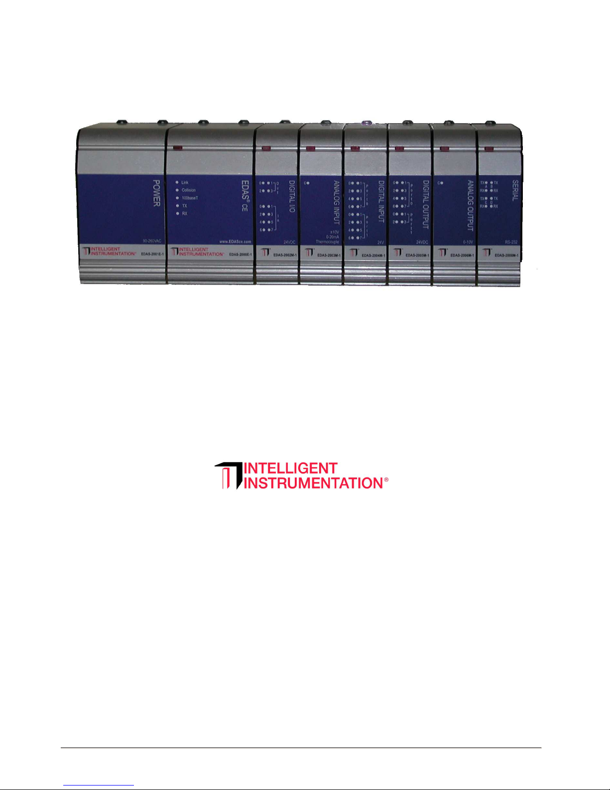
The EDAS CE is an open-architecture monitoring and control system based
on the Windows CE operating system. The EDAS CE features a 32-bit
processor with built-in 10/100BaseT Ethernet connectivity and a modular
I/O system. This combination makes the EDAS CE suitable for a wide range
of monitoring and control systems. The EDAS CE’s open architecture allows
the user to develop a wide range of embedded control, machine and process
monitoring applications using C/C++ or WebDevice development tools.
The built-in 10/100BaseT network, including a TCP/IP stack, enables
applications running on the EDAS CE unit to communicate with other
computers and other EDAS CE units on a network. The EDAS CE can operate
as a stand-alone system or as part of a plant- or factory- wide
monitoring/control system.
FIGURE 1.1 Typical EDAS CE System
1.1 Modules
An EDAS CE system consists of a power module, a base unit and I/O modules
as needed to meet the specific needs of the targeted application. All the
modules are plug-and-play, requiring no system configuration. Up to 12
I/O modules may be used, allowing for systems of up to 192 I/O points.
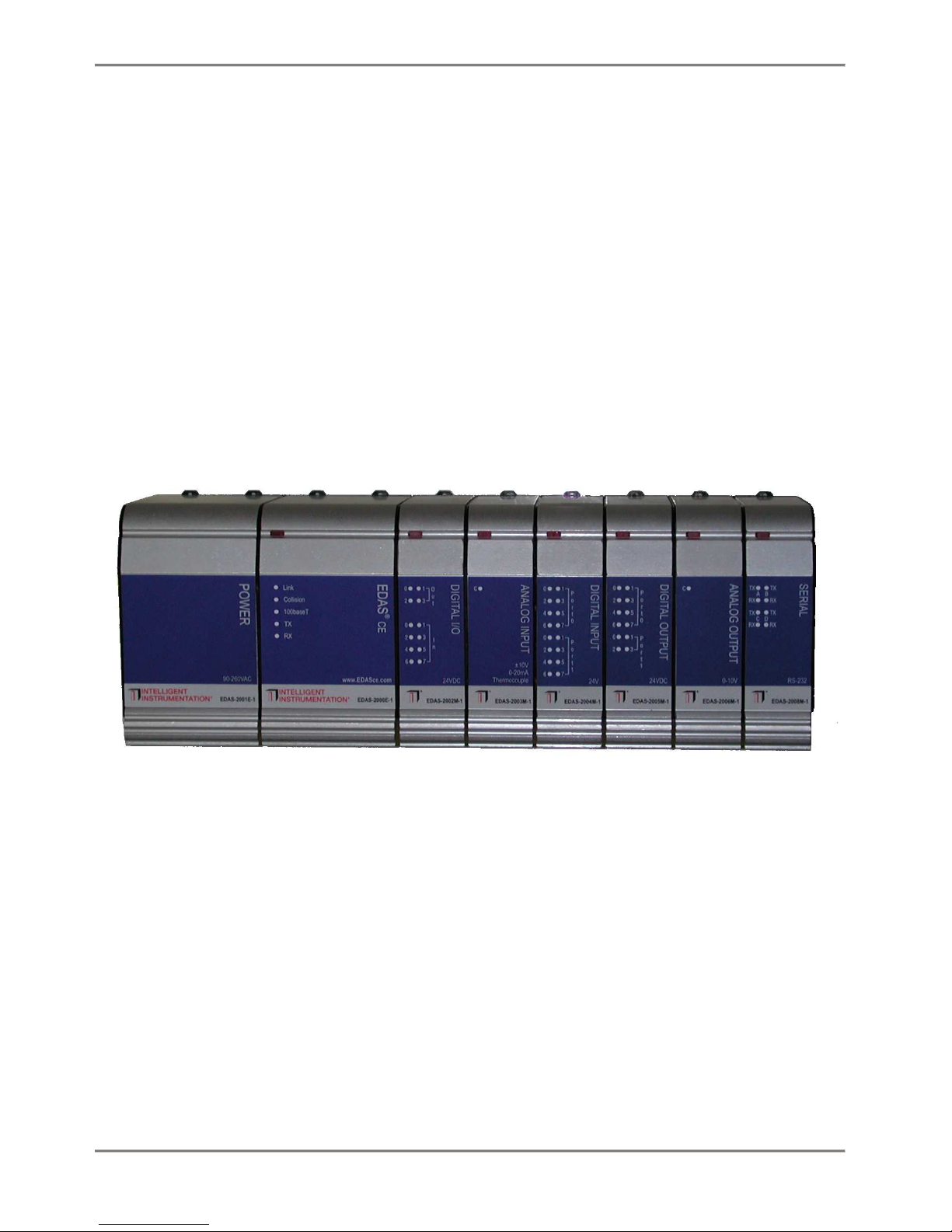
1.1.1 Base Unit
Each system requires one EDAS-2000E base (processor) unit. The base unit
includes the CPU, Ethernet connectivity, and an RS-232 port. The 32-bit
Hardware and Installation 1
Page 8
embedded processor runs the Windows CE 3.0 operating system, providing
real-time and multi-tasking capabilities.
FIGURE 1.2 EDAS-2000E Base Unit
The EDAS-2000E base unit includes the following features:
o 32 Bit embedded processor
o Windows CE Operating System
o 64 MB RAM
o 64 MB CompactFlash (1GB maximum)
o 1 RS-232 serial port
o Optional Non-volatile Battery RAM (128 kB)
o Network standards (TCP/IP, UDP, SNMP, DHCP)
o WebDevice (embedded Web server)
1.1.1.1 Application Development
Applications may be developed to execute on the EDAS CE using Microsoft’s
eMbedded Visual Tools and the eMbedded Visual C/C++ programming language.
Applications developed in C/C++ use the CE Link API for reading and
writing I/O points on the optional modules. Network and serial port
communications use the standard Windows 32 API. See Chapter 3:
Developing Custom Programs.
The EDAS CE includes a program (suprcate.exe) that runs on the EDAS CE as
a data server. A PC or other computer can open a connection and issue
commands to read and write the EDAS CE I/O points. Applications which
communicate with suprcate.exe use the Net Link API. The Net Link API
supports Visual C/C++ and Visual Basic on the Windows (98/Me/NT/2000)
Hardware and Installation 2
Page 9

Platform and C on Unix platforms. See the Net Link Manual for more
information.
1.1.1.2 EDAS-2000E Base Unit Specifications
All specifications are typical at 25° C unless otherwise noted.
Parameter Condition Specification
Processor AMD Elan SC400
Operating System Windows CE 3.0
DRAM Memory 64 MB
72-pin EDO SIMM 60 ns
Compact Flash 64 MB (1GB maximum)
Ethernet 10/100BaseT (RJ-45)
Serial Port 1 RS-232 (up to 115 k Baud)
Power consumption +5 VDC 1.5 A maximum
Dimensions inches
mm
Temperature Range Operating 0-60 °C
TABLE 1.1 EDAS-2000E-1 Base Unit Specifications
4.55D x 5.9H x 3.35W
116D x 150H x 85W
1.1.1.3 Ethernet
The base unit features a 10/100BaseT port. The unit has 5 red LED’s used
to display information about the Ethernet connection.
1. Link: Good link when on.
2. Collision: Collision detected when on.
3. 100BaseT: Indicates 100BaseT connection when on. When off,
connection is 10BaseT or no connection exists.
4. TX: Transmitting.
5. RX: Receiving.
1.1.1.4 Serial Port
The unit has a single serial port, COM1. The serial port can be used to
configure the unit’s network settings and real-time clock. See section
2.2 MonitorCE.
An application may read and write data to this port (COM1) using the
standard Win32 API.
Hardware and Installation 3
Page 10

1.1.1.5 Real-Time Clock Battery
The base unit contains a 3.0 V lithium battery that powers the Real-Time
Clock when external power is absent. Battery life is approximately two
years when the unit is not powered. When the unit is on external power,
battery life is longer since the battery does not have an appreciable
power draw in this condition. To replace the battery, remove the right
hand cover of the unit.
FIGURE 1.3 Real-time Clock Battery and DRAM Access
Hardware and Installation 4
Page 11

1.1.1.6 DRAM
The EDAS-2000E can use up to 64 Mbytes of DRAM. The DRAM is industry
standard 5 V, 72- pin EDO or FPM. To change the DRAM module, remove the
right hand cover of the unit.
1.1.1.7 Compact Flash
The EDAS-2000E uses standard Compact Flash memory for non-volatile
storage of the operating system and drivers. The remaining memory can be
used by the applications for non-volatile application or data storage.
The CompactFlash is accessed as part of the unit’s file system. The
CompactFlash can be replaced with a larger card to providing additional
storage capability.
1.1.1.8 Reset/Watchdog Timer
The unit has a watchdog timer that may be activated by an application.
When the watchdog timer is activated, an application must "tickle" the
timer every 2000 ms or the unit will reboot.
1.1.1.9 NV-RAM Option
The EDAS-2000E is available with an optional 128 kbytes of battery RAM.
The NV-RAM provides high speed non-volatile storage. Applications such a
fast control loops can use the NV-RAM to hold state variables, allowing
an application to recover variables after a power loss.
The NV-RAM is memory mapped to 0xA0000 to 0xBFFFF.
Hardware and Installation 5
Page 12
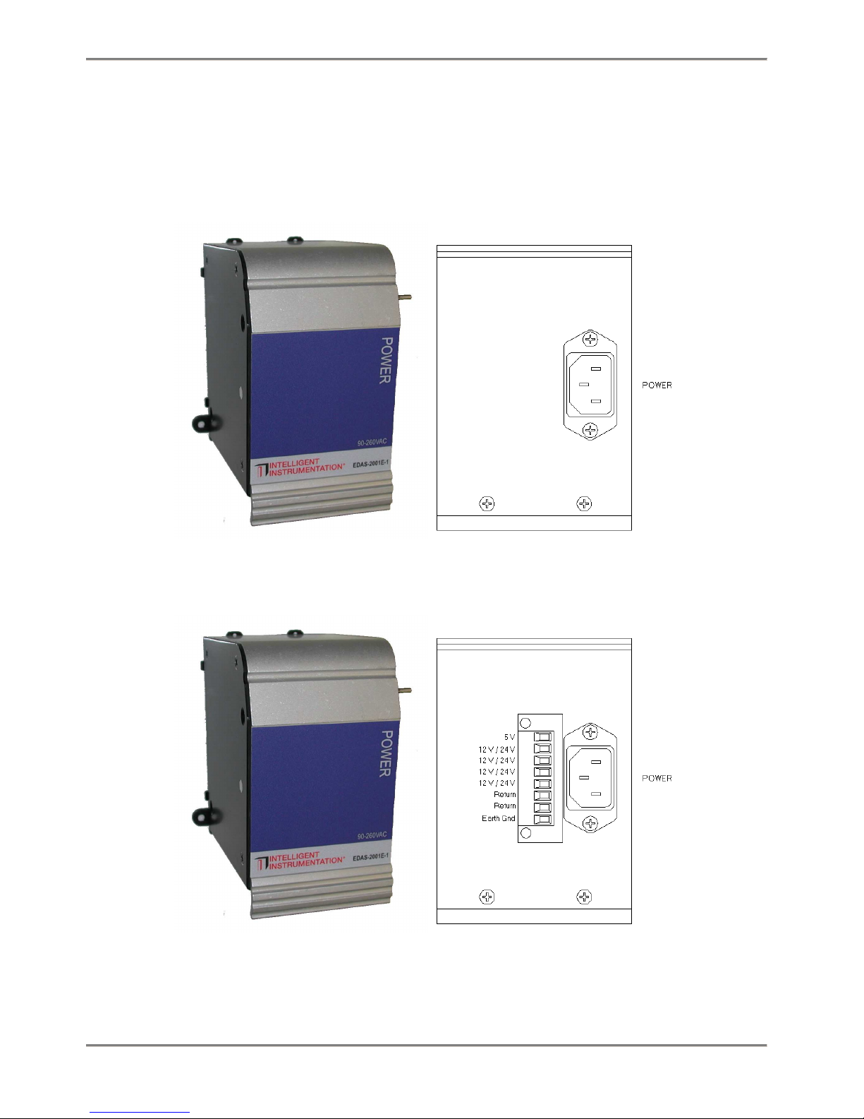
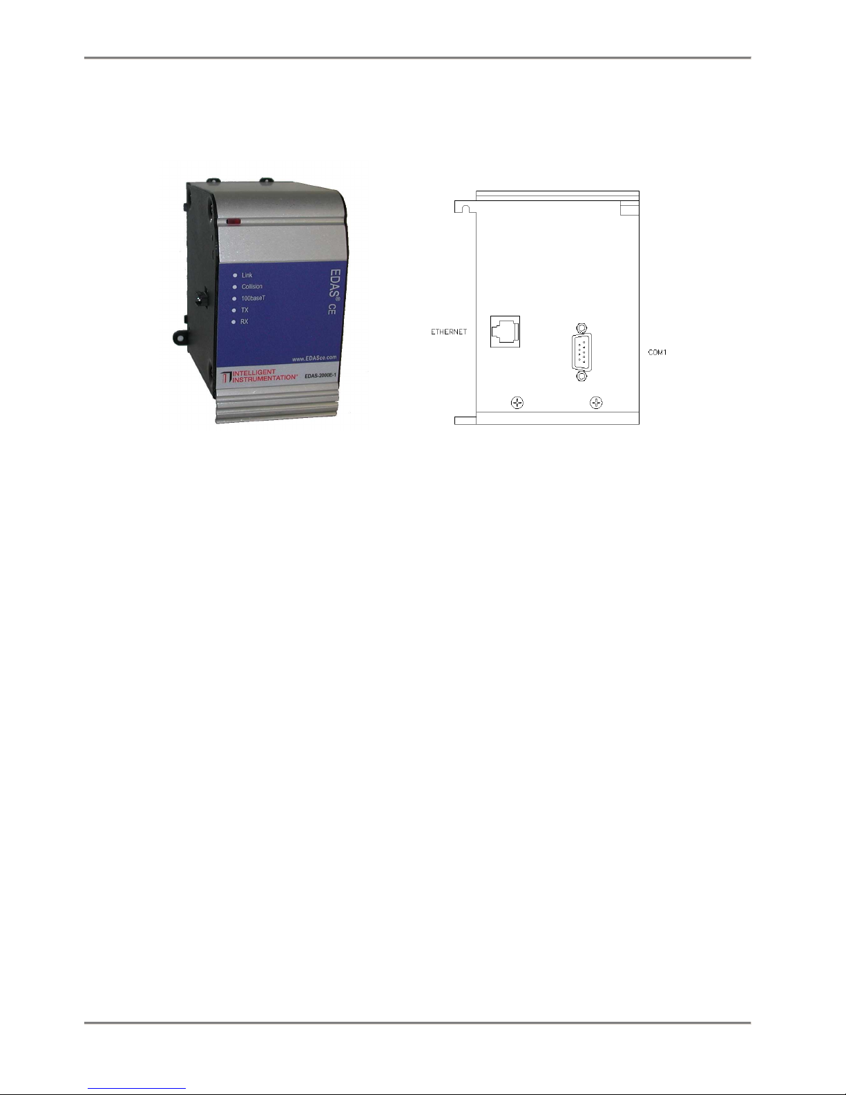
1.1.2
The EDAS-2001E power supply module provides power for the base unit and
attached modules. The EDAS-2001E can accept line voltages of 90 - 260
VAC @ 50 - 60 Hz.
Power Supply
FIGURE 1.4 EDAS-2001E-1 Power Supply Module
FIGURE 1.5 EDAS-2001E-2 and -3 Power Supply Module
Hardware and Installation 6
Page 13

1.1.1.10 EDAS-2001E Power Supply Specifications
The EDAS-2001E supplies 5 VDC power to the CPU module which in turn
supplies power to the I/O modules. The -2 and -3 have quick a disconnect
connector that can be used to pull 5VDC and 12 VDC (-2) or 24 VDC (-3)
power from the supply to power other components in your system.
All specifications are typical at 25° C unless otherwise noted.
Parameter Condition Specification
Input Voltage 90 - 260 VAC
Input Frequency 50 - 60 Hz
Output Voltage
EDAS-2001E-1 5.0 V +/- 5%
EDAS-2001E-2 5.0 V +/- 5%
12.0 V +/- 5%
EDAS-2001E-3 5.0 V +/- 5%
24.0 V +/- 5%
Output Current
EDAS-2001E-1 5 V 10.0 A max
EDAS-2001E-2 5 V
12 V
EDAS-2001E-3 5 V
24 V
Agency Approvals Tested to UL 60950
Dimensions inches
mm
Temperature Range Operating 0-60 °C
TABLE 1.2 EDAS-2001E Power Supply Specifications
7.0 A max
2.5 A max
7.0 A max
2.0 A max
4.55D x 5.9H x 3.35W
116D x 150H x 85W
1.1.1.11 Power Connector
The EDAS-2001E has a standard IEC power connector. Due to the wide range
of power sources and distance from the EDAS system a power cord is not
included with this module.
Hardware and Installation 7
Page 14

1.1.3 Digital I/O Module
The EDAS-2002M Digital I/O Module has 8 digital inputs and 4 digital
outputs. The digital inputs and outputs are designed for 24 VDC
operation. All of the digital inputs and outputs provide 500 V channel
to channel isolation with one return per channel. LEDs provide visual
feedback on the channels’ current states. The digital inputs can be
individually configured for normal (high/low), counter or latched
operation. The digital outputs can individually configured for normal
(open/closed), pulsed, delayed and square wave output.
Hardware and Installation 8
Page 15
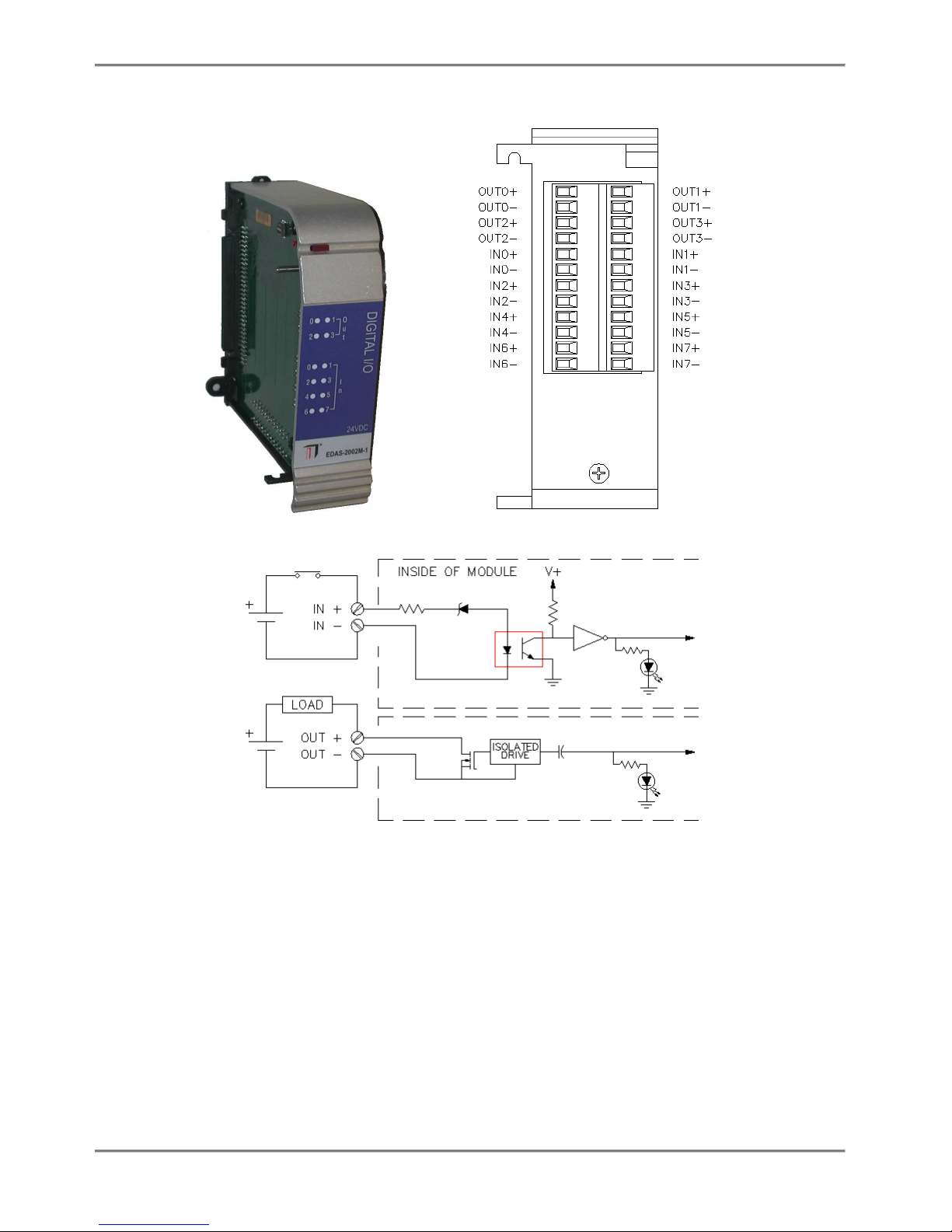
FIGURE 1.6 EDAS-2002M Digital I/O module
1.1.1.12 Input Functions
The Digital I/O Module provides the following digital input functions.
The inputs can be configured on a channel by channel basis.
o Normal: Reads the current sates of the input (low/high).
o Counter: 24 bit up/down counter, 250 Hz maximum count rate.
o Latched: The input is latched on a low-to-high, high-to-low, or any
change of state.
Hardware and Installation 9
Page 16

o High Speed Counter: Channel 0 only, 16-bit counter at 20 kHz maximum
count rate.
1.1.1.13 Output Functions
The Digital I/O Module provides the following digital output functions.
The outputs can be configured on a channel by channel basis.
o Normal: Set output to desired state (open/closed)
o Pulsed: Set output active for a specified amount of time.
o Delayed: Set output active after the specified time delay.
o Square wave: Generate a square wave with the specified period, 250 Hz
maximum.
1.1.1.14 EDAS-2002M Digital I/O Module Specifications
All specifications are typical at 25° C unless otherwise noted.
Parameter Condition Specification
Digital Input 8 inputs
Input Voltage Low 3.0 V max
Input Current Low Vin = 0.5 V > 500 nA
Input Voltage High 9 V min, 30 V max
Input Current High Vin = 24 V 5 mA max
Low Speed Counter Ch 0 through 7
Size 24 bit
Frequency 250 Hz max
High Speed Counter Channel 0 only
Size 16 bit
Frequency 20 kHz max
Digital Output FET output 4 Outputs
On resistance
On current 0.5 A max
On Voltage 0.8 V max
Off Voltage 27 V max
Isolation Inputs and Outputs
Channel - Channel 500 V max
Channel - Bus 1500 V max
Current Consumption 5 V 200 mA max
Dimensions inches
mm
Temperature Range Operating 0-60 °C
0.03 Ω
4.55D x 5.9H x 1.74W
116D x 150H x 42W
Hardware and Installation 10
Page 17

TABLE 1.3 EDAS 2002M-1 Digital I/O Module Specifications
Hardware and Installation 11
Page 18
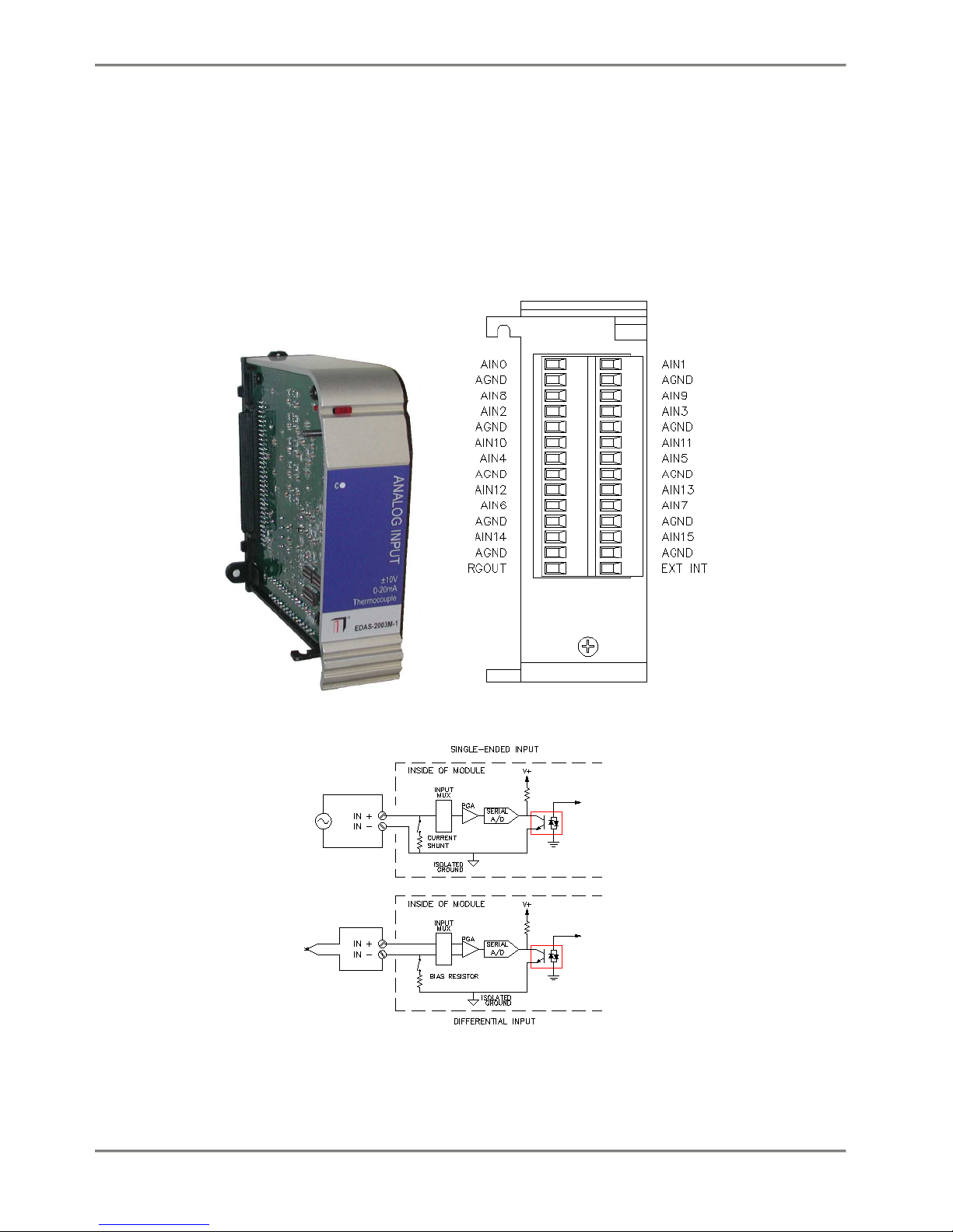
1.1.4 Analog Input Module
The EDAS-2003M Analog Input Module can read voltage, current and
thermocouple inputs. Voltage, current or thermocouple readings can be
configured on a channel by channel basis, allowing one analog input
module to read a combination of voltage, current or thermocouple inputs.
FIGURE 1.7 EDAS-2003M Analog Input module
Hardware and Installation 12
Page 19

The analog input stage consists of a 16 channel multiplexer (MUX),
followed by a programmable gain amplifier (PGA), feeding a 12-bit analog
to digital converter (ADC). The output of the ADC is isolated and
presented to the system bus. The MUX is capable of providing 16 singleended inputs, 8 differential inputs or a mixed combination to the PGA.
The PGA has gains of 1, 10 and 100. The ADC supports 0-10 V and ±10 V
ranges.
Current Readings: the module has 16 resistors (500 Ω) that may be
switched between the individual input channels and ground allowing the
unit to make current measurements in the range 0-20 mA.
Thermocouple readings: the module features a built-in Cold Junction
Compensator (CJC), which may be switched in to channel zero.
Additionally the module has 100 kΩ input bias return resistors that may
be switched in to provide an input bias current path for the PGA
1.1.1.15 Configuring Inputs
Each Analog Input channel can be configured for voltage input, current
input, or thermocouple input.
To configure a channel for voltage input:
1: Set the appropriate switches to disable current mode (SW2-1
through SW2-8 and SW3-1 through SW3-8). See the table below.
2: Set the appropriate switches to disable input ground return
resistor (SW1-1 through SW1- 8).
3: The gain and range are set through software control.
To configure a channel for 0-20 mA current input:
1: Set the appropriate switches to enable current mode (SW2-1 through
SW2-8 and SW3-1 through SW3-8). See the table below. This
configuration requires the channel to be read as a single-ended
input.
2: Set the appropriate switches to disable ground return (SW1-1
through SW1-8).
3: In software set the PGA gain to 1 and the ADC Range to 0-10 V.
To configure an input for thermocouple input:
Note: Thermocouple can only be read on differential input channels 1
through 7. Channel 0 is used to read the CJC value.
1: Enable the differential ground return switches for the appropriate
channels (SW1-1 through SW1-8). See table below.
Hardware and Installation 13
Page 20

2: Enable the CJC circuit (SW3-9). This will connect the CJC circuit
to channel 0 to be read as a single-ended analog input. If SW3-10
is turned on with SW3-9, the CJC may be read in differential mode.
Switch Number Switch ON Switch OFF
SW1-1 GND return for differential Channel A0 No GND return
SW1-2 GND return for differential Channel A1 No GND return
SW1-3 GND return for differential Channel A2 No GND return
SW1-4 GND return for differential Channel A3 No GND return
SW1-5 GND return for differential Channel A4 No GND return
SW1-6 GND return for differential Channel A5 No GND return
SW1-7 GND return for differential Channel A6 No GND return
SW1-8 GND return for differential Channel A7 No GND return
SW2-1 Current mode enable Channel 8 Voltage mode enable Channel 8
SW2-2 Current mode enable Channel 9 Voltage mode enable Channel 9
SW2-3 Current mode enable Channel 10 Voltage mode enable Channel 10
SW2-4 Current mode enable Channel 11 Voltage mode enable Channel 11
SW2-5 Current mode enable Channel 12 Voltage mode enable Channel 12
SW2-6 Current mode enable Channel 13 Voltage mode enable Channel 13
SW2-7 Current mode enable Channel 14 Voltage mode enable Channel 14
SW2-8 Current mode enable Channel 15 Voltage mode enable Channel 15
SW3-1* Current mode enable Channel 0 Voltage mode enable Channel 0
SW3-2 Current mode enable Channel 1 Voltage mode enable Channel 1
SW3-3 Current mode enable Channel 2 Voltage mode enable Channel 2
SW3-4 Current mode enable Channel 3 Voltage mode enable Channel 3
SW3-5 Current mode enable Channel 4 Voltage mode enable Channel 4
SW3-6 Current mode enable Channel 5 Voltage mode enable Channel 5
SW3-7 Current mode enable Channel 6 Voltage mode enable Channel 6
SW3-8 Current mode enable Channel 7 Voltage mode enable Channel 7
SW3-9 CJC enable CJC Disable
SW3-10 CJC differential mode CJC single-ended mode
* must be OFF when CJC circuit is enabled
Ground return resistors are 100 kΩ
TABLE 1.4 Current and Ground Return Resistor Switch Settings
1.1.1.16 Hardware / Software Pacing
The Analog Input Module has provisions for pacing (starting) conversions
by software or by one of two hardware start convert sources. These two
hardware sources are an internal 24-bit Rate Generator and a digital
input (EXT INT). The EXT INT input may also be used as a trigger signal
Hardware and Installation 14
Page 21

to control when conversions are started and stopped. This allows for the
support of Stop on Trigger, Stop on delay after Trigger, Start on Trigger
and N Conversions after Trigger modes.
1.1.1.17 Channel Scanner
The Analog Input Module has a hardware channel scanner that scans
channels 0 through N. The scanner increments the channel by one each time
a conversion is started and wraps back to channel 0. The value of N is
set by software.
1.1.1.18 Rate Generator
The Analog Input Module provides a 24-bit rate generator to pace (start)
conversions. The base clock for this rate generator is 4 MHz providing a
resolution of 250 nsec. This allows the rate generator to be set to an
output range of 2 MHz to 0.238 Hz (4.2 s). The Rate Generator output is
also available on the RGOUT terminal on the I/O connector.
1.1.1.19 EDAS 2003M Analog Input Specifications
All specifications are typical at 25 °C unless otherwise noted.
Parameter Condition Specification
Number of Channels Single-ended 16
Differential 8
Resolution 12 bits (1 part in 4096)
Voltage Ranges Gain = 1 ±10 V, 0 to 10 V
Gain = 10 ±1 V, 0 to 1 V
Gain = 100 ±0.1 V, 0 to 0.1 V
Current Ranges Gain = 1 0 to 20 mA
Overvoltage Protection Power on or off -40 V to +55 V
Gain Accuracy Gain = 1 ±0.012%
Gain = 10 ±0.08%
Gain = 100 ±0.08%
Input Offset Voltage Gain = 1 ±1.2 mV
Gain = 10 ±0.12 mV
Gain = 100 ±0.012 mV
Input Bias Current 500 pA
Hardware and Installation 15
Page 22

Input Impedance Voltage Mode
Current Mode
Common-Mode Range ±10 V
Common-Mode Rejection Ratio Gain = 1 80 dB
Gain = 10 86 dB
Gain = 100 92 dB
Noise RMS/p-p G=1 0.5 LSB/2 LSB
Mono tonicity No missing codes 12 bits
Linearity ±1 LSB
Rate Generator Resolution 250 nS
Output Frequency 0.238 Hz to 200 kHz
Isolation Input to Bus
VAC rms for 60 s
Power Consumption +5 V 400 mA
Dimensions inches
mm
Temperature Range Operating 0-60 °C
TABLE 1.5 EDAS-2003M Analog Input Module Specifications
10 GΩ || 3 pF
487 Ω
1500 V
4.55D x 5.9H x 1.74W
116D x 150H x 42W
Hardware and Installation 16
Page 23
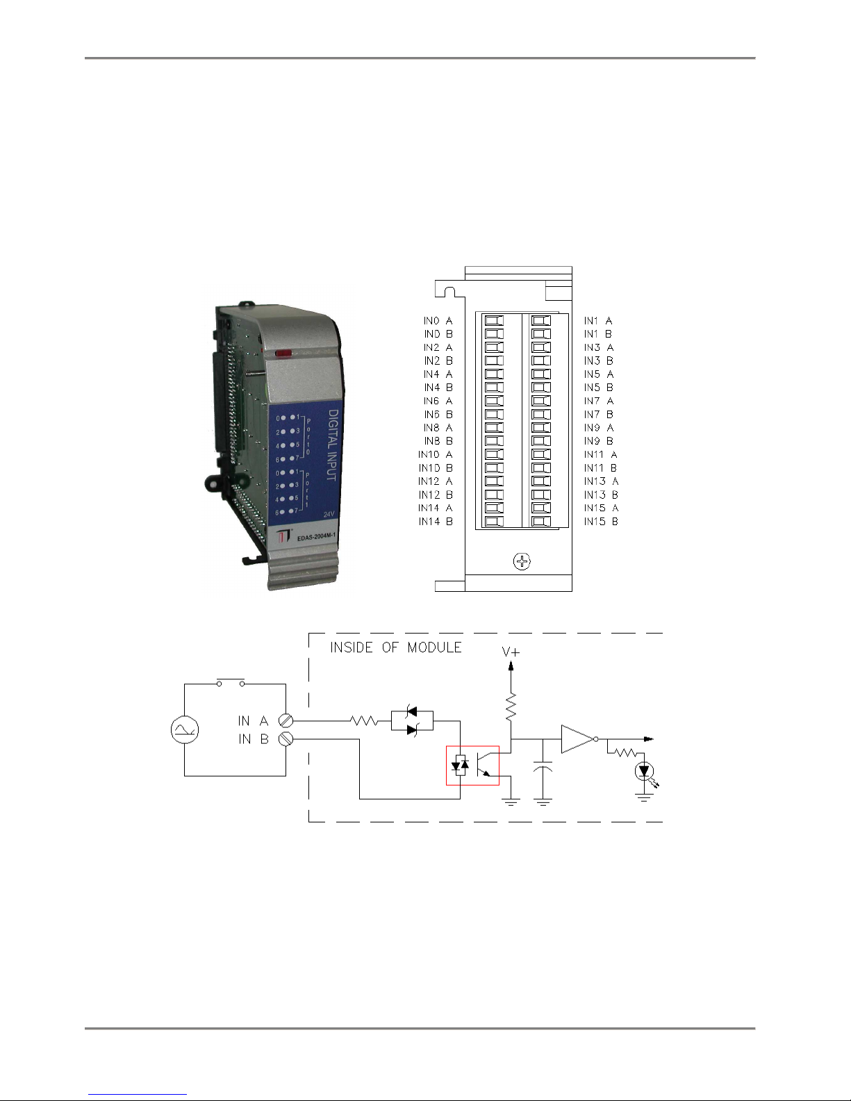
1.1.5 Digital Input Module
The EDAS-2004M Digital Input Module provides 16 channels of 5V, 24 V, 120
V or 240 V input. The digital inputs provide 500 V channel-to-channel
isolation with one return per channel. The 16 channels are arranged as
two 8 bit ports, Port 0 and Port 1. LEDs provide visual feedback on the
channels’ present states.
FIGURE 1.8 EDAS-2004M Digital Input module
Hardware and Installation 17
Page 24

1.1.1.20 EDAS-2004M Digital Input Module Specifications
All specifications are typical at 25° C unless otherwise noted.
Parameter Condition Specification
Digital Inputs Opto Isolators 16 inputs
EDAS-2004M-1
Low 0-3 V
High 9-30 V
Current Vin = 24V 2 mA max
EDAS-2004M-2
Low 0-20 V
High 70-130 V
Current Vin = 120V 2 mA max
EDAS-2004M-3
Low 0-40 V
High 140-250 V
Current Vin = 240V 2 mA max
EDAS-2004M-4
Low 0-1 V
High 2-10 V
Current Vin = 5V 3 mA max
Turn-on time 6 mS max
Turn-off time 35 mS max
Isolation Outputs
Channel - Channel 500 V max
Bus - Channel 1500 V max
Current Consumption 5 V 500 mA max
Dimensions inches
mm
Temperature Range Operating 0-60 °C
TABLE 1.6 EDAS-2004M Digital Input Module Specifications
4.55D x 5.9H x 1.74W
116D x 150H x 42W
Hardware and Installation 18
Page 25
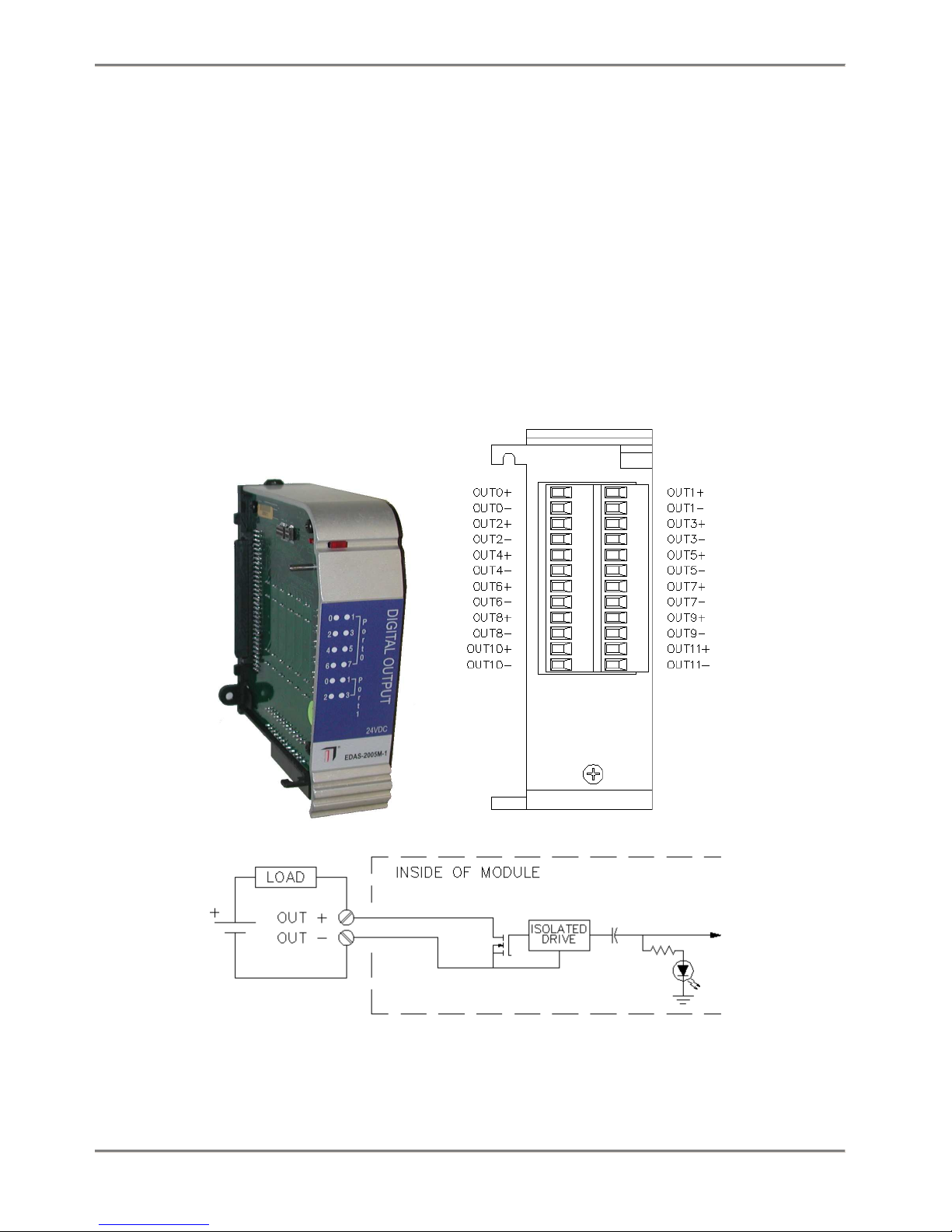
1.1.6 Digital Output Modules
The EDAS-M Digital Output Modules provide 12 channels of open drain, 24
VDC (EDAS-2005M-1) or 360 VDC (EDAS-2005M-2) digital outputs. The digital
outputs have 500 V channel-to-channel isolation with one return per
channel. The 12 channels are arranged as two ports. Port 0 has 8
channels and Port 1 has 4 channels. This module supports read back
allowing the software to determine the value last commanded for each
output. Each channel has a hardware switch that determines the channel’s
power-on state. When a switch is in the on position during the power-up
reset, the corresponding channel will be turned on.
FIGURE 1.9 EDAS-2005M Digital Output Modules
Hardware and Installation 19
Page 26

1.1.1.21 EDAS-2005M Digital Output Modules Specifications
All specifications are typical at 25° C unless otherwise noted. Maximum
voltage or current are dependent on power dissipation. Please contact support for particular
current/voltage operating points.
TABLE 1.7 EDAS-2005M Digital Output Modules Specifications
Parameter Condition Specification EDAS-2005M-1 Specification EDAS-2005M-2
Digital Output FET output 12 channels, 27VDC max 12 channels, 360VDC max
On resistance 0.03 Ω 5 Ω, typ
On current 0.5 A max 260 mA max
On Voltage 0.8 VDC max 2 VDC max
Off Voltage 27 VDC max 360 VDC max
Isolation Outputs
Channel - Channel 500 V max 500 V max
Channel - Bus 1500 V max 1500 V max
Current Consumption 5 V 160 mA max 160 mA max
Dimensions inches
mm
Temperature Range Operating 0-60 °C 0-60 °C
4.55D x 5.9H x 1.74W
116D x 150H x 42W
4.55D x 5.9H x 1.74W
116D x 150H x 42W
Hardware and Installation 20
Page 27
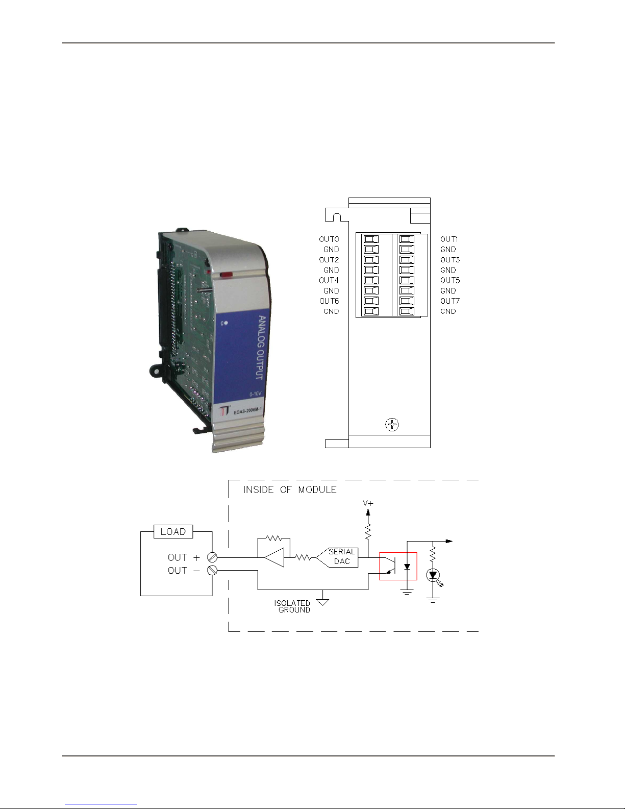
1.1.7 Analog Output Module
The EDAS-2006M Analog Output Module provides 8 channels of 0 to 10 V
analog output. This module uses eight 12-bit digital-to-analog converters
(DAC). The module has a single LED that will blink when an output is
updated.
FIGURE 1.10 EDAS-2006M Analog Output Module
Hardware and Installation 21
Page 28

1.1.1.22 EDAS-2006M Analog Output Module Specifications
All specifications are typical at 25° C unless otherwise noted.
Parameter Condition Specification
Number of Outputs 8
Resolution 12-bits (2.44 mV)
Output Range 0-10 V
Output current 10 mA max
Accuracy +/- 5.2 LSB (13 mV)
Isolation Outputs
Bus - Channel 1500 V max
Current Consumption 5V 450 mA max
Dimensions inches
mm
Temperature Range Operating 0-60 °C
TABLE 1.8 EDAS-2006M Analog Output Module Specifications
4.55D x 5.9H x 1.74W
116D x 150H x 42W
Hardware and Installation 22
Page 29
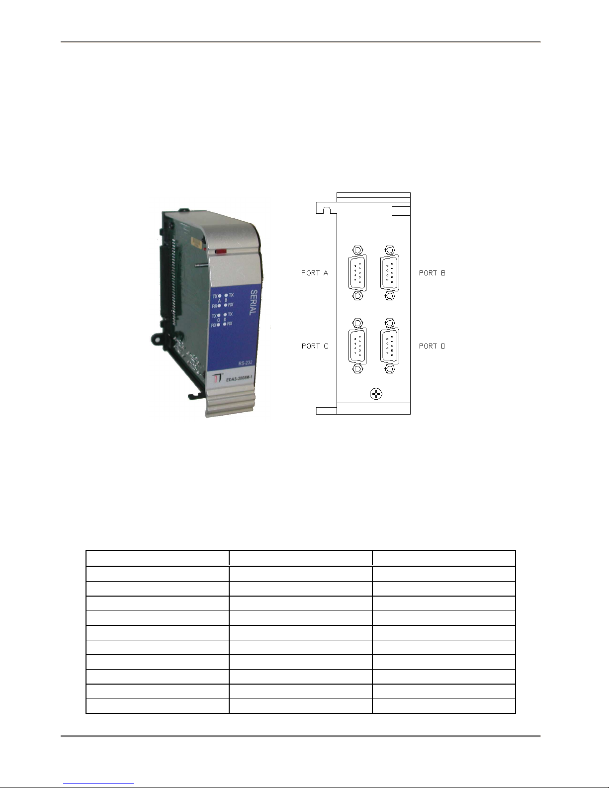
1.1.8 Serial Module
The EDAS-2008M Serial Module provides four RS-232 serial ports. The
serial ports are interfaced through 9-pin D-subminiature connectors on
the bottom of the unit. The EDAS- 2000E base unit can support 6 serial
modules for a total of 25 serial ports, one on the base plus 24 on
additional serial modules.
FIGURE 1.11 EDAS-2008M Serial Port Module
1.1.1.23 EDAS-2008M Serial Module Specifications
All specifications are typical at 25° C unless otherwise noted.
Parameter Condition Specification
Number of Ports 4 Ports
Serial Outputs
Output Voltage Low 3 kΩ load -5.0 V max
Output Voltage High 3 kΩ load +5.0 V max
Serial Inputs
Input Impedance 3 kΩ min 7 kΩ max
Input Threshold Low 0.8 V min
Input Threshold Low 2.4 V max
Isolation None
Dimensions inches 4.55D x 5.9H x 1.74W
Hardware and Installation 23
Page 30

mm 116D x 150H x 42W
Temperature Range Operating 0-60° C
TABLE 1.9 EDAS-2008M Serial Port Module Specifications
1.1.1.24 COM port mappings
The COM ports on the serial module are mapped as COM2 through COM9 on the
first two serial module, SER1 through SER8 on the next two and ASY1
through ASY8 on the last two. .
Port Mapping
COM1 COM1 CPU
COM2 Port A 1
COM3 Port B 1
COM4 Port C 1
COM5 Port D 1
COM6 Port A 2
COM7 Port B 2
COM8 Port C 2
COM9 Port D 2
SER1 Port A 3
SER2 Port B 3
SER3 Port C 3
SER4 Port D 3
SER5 Port A 4
SER6 Port B 4
SER7 Port C 4
SER8 Port D 4
ASY1 Port A 5
ASY2 Port B 5
ASY3 Port C 5
ASY4 Port D 5
ASY5 Port A 6
ASY6 Port B 6
ASY7 Port C 6
ASY8 Port D 6
Port
TABLE 1.10 COM port mappings
Module
Hardware and Installation 24
Page 31

1.1.9 Relay Output Module
The EDAS-2010M Relay Output Module provides 12 channels of singlepole/single-throw normally open relay contacts capable of switching 2 A
at either 250 VAC or 30 VDC. This module has power-up initialization
hardware allowing the configuration of the power-up state of each output.
FIGURE 1.12 EDAS-2010M Relay Output Module
Hardware and Installation 25
Page 32

1.1.1.25 EDAS-2010M Relay Output Module Specifications
All specifications are typical at 25° C unless otherwise noted.
Parameter Condition Specification
Relay Output Contact closure 12 outputs
Closed resistance 0.03 Ω
Closed current 2.0 A max
Voltage 250 VAC max, 30 VDC max
Isolation Outputs
Channel - Channel 500 V max
Bus - Channel 1500 V max
Current Consumption 5 V 450 mA max
Dimensions inches
Mm
Temperature Range Operating 0-60 °C
TABLE 1.11 EDAS-2010M Relay Output Module Specifications
4.55D x 5.9H x 1.74W
116D x 150H x 42W
Hardware and Installation 26
Page 33

1.1.10 Digital Output (Triac) Module
The EDAS-2011M Digital Output Module provides 12 solid state (triac)
outputs capable of switching 2 A at 120 VAC. This module has power-up
initialization hardware allowing users to configure the power-up state of
each output.
FIGURE 1.13 EDAS-2011M Digital Output (Triac) module
Hardware and Installation 27
Page 34

1.1.1.26 EDAS-2011M Digital Output Module (Triac)
Specifications
Parameter Condition Specification
Triac Output Contact closure 12 outputs
Closed resistance 0.03 Ω
Switching current 25° C
60° C
Voltage 24 VAC to 240 VAC
Isolation Outputs
Channel – Channel 500 V max
Bus – Channel 1500 V max
Current Consumption 5 V 200 mA max
Dimensions inches
mm
Temperature Range Operating 0-60° C
TABLE 1.12 EDAS-2011M Digital Output Module Specifications
2.0 A max
1.0 A max
4.55D x 5.9H x 1.74W
116D x 150H x 42W
Hardware and Installation 28
Page 35

1.1.11 Quadrature Module
The EDAS-2015M Quadrature Module provides 2 independent quadrature
decoder channels which can also be used as high-speed 32-bit counter
channels. Each channel also provides two outputs which can be controlled
manually or configured to output counter channel state information. Each
channel also provides two inputs which can be used for counter channel
control or for general-purpose digital input.
FIGURE 1.14 EDAS-2015M Quadrature module
Hardware and Installation 29
Page 36

1.1.1.27 EDAS-2015M Quadrature Module Specifications
Parameter Condition Specification
Quadrature Inputs/Up-Down
Counters
Inputs 24VDC compatible 2 count control per quadrature
General-purpose Modes Separately configured for each
Outputs 24VDC compatible 2 per quadrature channel, 5-
Comparator Modes Separately configured for each
Isolation Channel – Channel 500 V max
Bus – Channel 1500 V max
Current Consumption 5 V 200 mA max
Dimensions inches
Temperature Range Operating 0-60° C
TABLE 1.13 EDAS-2015M Quadrature Module Specifications
2. Maximum input rate is
500kSteps/second, 2MHz for
counting
channel, 2 general purpose, 0-3V
low, 9-30V high
Latch, preload, enable, general-
input
output
mm
purpose
30VDC
<, >, <=, >=, =, ≠, general purpose
4.55D x 5.9H x 1.74W
116D x 150H x 42W
Hardware and Installation 30
Page 37

1.2 Installation
1.1.12 DIN rail Mounting
The EDAS CE systems was designed to be mounted using 35 mm DIN-rails. 35
mm DIN-rails are available in 7.5 mm and 15 mm heights.
FIGURE 1.15 Side View of DIN rail for 7.5 mm and 15 mm heights
The EDAS CE modules are attached to the DIN-rial by first hooking the
bottom of the DIN-rail clip on the DIN-rail and the rotating the EDAS CE
module until it snaps on to the DIN-rail.
FIGURE 1.16 Installing modules on a DIN rail
1.1.13 Attaching a module to a DIN Rail
The EDAS CE modules are installed one at a time on to the DIN rail and
then slid together. Install the Power Supply module first, followed by
the Base unit, followed by I/O modules.
Hardware and Installation 31
Page 38

1.1.14 Removing Modules from a DIN Rail
Using a screwdriver, lift the retaining spring until the module releases
from the DIN rail. Note: Some modules have two retaining springs. To
release the module from the DIN rail, lift both retaining springs.
Hardware and Installation 32
Page 39

Chapter 2:Utilities
2.1 Summary of Utilities
The EDAS CE unit is shipped with a number of pre-installed utilities
which are summarized in the table shown below. These utilities simplify
the development and deployment of applications on the EDAS CE. A brief
description of each utility follows the table shown below.
MonitorCE
Configure network settings
Upload / download files
Run an application
View a list of running applications
Terminate an application
Reboot the EDAS CE
Write an application
Set the unit’s real-time clock
Remotely communicate with serial ports
Save registry settings
* See Chapter 3: Developing Custom Programs for more information.
TABLE 2.1 Utility Program Cross-reference
LCmdSet
Remote Manager
Time Synchronization
SerialSocket
CE Flush
eMbedded Visual Tools *
Utilities 33
Page 40

1.1.15 MonitorCE
The MonitorCE program allows a computer to connect to the EDAS CE in
order to set the unit’s network parameters and real-time clock. With a
null modem cable connected between COM1 on the EDAS CE and one of the
computer’s serial ports, a communications application, such as
HyperTerminal, may be used to configure many of the EDAS CE’s operating
parameters.
1.1.16 LCmdSet
The LCmdSet application runs on the EDAS CE, allowing a remote client to
open a Telnet session over the Ethernet network to the EDAS CE. Through
this Telnet session, you can change the EDAS CE’s network configuration,
serial port configurations, run programs and reboot the unit. The LCmdSet
utility can only be used to change configuration settings after the
initial configuration settings are made using the MonitorCE program and a
functional network connection has been established.
If the EDAS CE will be running on a network accessible from the Internet,
be sure to configure the security settings of LCmdSet.
1.1.17 Remote Manager
The Remote Manager is a Web-based management tool that allows a user to
perform management functions on the EDAS CE unit using a Web browser. A
user with the correct user name and password can download and upload
files, run and terminate programs, reboot the unit, read and write the
unit’s I/O points, etc.
1.1.18 DebugLauncher
The DebugLauncher application runs on the EDAS CE unit and enables the
EDAS CE to make a connection to Microsoft eMbedded Visual Tools on a
development computer. This allows remote downloading and debugging of
custom programs.
1.1.19 TimeSync
The Time Synchronization application runs on the EDAS CE and can be
configured to synchronize the EDAS CE’s real-time clock with an external
time standard. This is useful for having the real-time clock maintain
time in synchronization with other devices.
Utilities 34
Page 41

1.1.20 SerialSocket
The SerialSocket application runs on the EDAS CE, providing a bridge
between the unit’s Ethernet and serial ports. When the SerialSocket
program is running on the EDAS CE, a remote computer can open a TCP/IP
socket to the EDAS CE and send and receive data to and from the EDAS CE’s
serial ports. This is useful for remotely accessing serial devices
connected to the EDAS CE’s COM ports.
1.1.21 CEFlush
The CEFlush program runs on the EDAS CE unit to write the current
registry settings to the Compact Flash card. This application is
typically used by developers that need to change registry settings.
Utilities 35
Page 42

2.2 MonitorCE
The MonitorCE program is used to configure the unit’s network setting and
real-time clock. By connecting a null modem cable between the serial
port on the EDAS-2000E and a serial port on a computer, a serial
communications program such as HyperTerminal can be used to configure the
EDAS CE. The EDAS CE’s network settings must be configured before any
network communications can be established. The MonitorCE program
automatically executes on the EDAS CE unit at start-up.
When the MonitorCE program is running, it monitors COM1 for commands.
When another application running on the EDAS CE attempts to open COM1,
the MonitorCE program closes, allowing the new program to take ownership
of COM1. If another program closes MonitorCE, restart the EDAS CE unit to
start it again.
1.1.22 Required Tools
To configure an EDAS CE unit, you need the following items:
o NULL modem serial cable to connect the EDAS CE to a computer.
o A computer with an RS-232 port and a serial communications program,
such as HyperTerminal.
Connect the NULL modem serial cable to the EDAS CE base unit’s COM1 port
and connect the other end of the cable to any available serial port on
the computer.
1.1.23 Configuring the Communications Program
Run a serial communications program, such as HyperTerminal, on the
computer and configure it as follows:
Baud rate: 9600
Parity: None
Data bits: 8
Stop bits:1
No flow control
Line terminator: CRLF (carriage return/line feed)
Instructions for using HyperTerminal follow in the next section.
Utilities 36
Page 43

2.2.1.1 Using HyperTerminal
This section discusses the HyperTerminal serial communications program.
However, other serial communications programs can be used.
To start HyperTerminal:
1. Open HyperTerminal using the Start menu on the computer. Click the
Hypertrm.exe icon.
2. In the Connection Description dialog, in the name field, type a
session name. Select an icon, and click the OK button.
3. In the Connect To dialog, verify the COMx port to which you connected
the null modem cable is selected and click the OK button. The COMx
Properties dialog opens.
4. In the Port Settings tabbed dialog, enter the Port Settings provided
above, and click the OK button.
5. In the New Connection window, open the File menu and select
Properties.
6. In the dialog named for the session that you named, select the
Settings tab.
7. Click the ASCII Setup button.
8. In the ASCII Setup dialog, in the ASCII Sending section of the
dialog, select the checkboxes for Send line ends with line feeds and
Echo typed characters locally.
9. In the ASCII Receiving section of the dialog, select the checkbox for
Append line feeds to incoming line ends and click the OK button.
10. In the dialog named for the session that you named, click the OK
button.
11. When you close the New Connection window, a pop-up dialog asks if you
want to save the new session that you named. Click the Yes, No, or
Cancel buttons.
1.1.24 Starting a MonitorCE Program Session
With the serial communications program running on the computer and the
EDAS CE powered up, start a MonitorCE program session. Note: From the
time power is applied to the EDAS CE it will take approximately 30
seconds before the MonitorCE will be ready to accept a connection.
To start a MonitorCE program session:
1. In the serial communications program window, type the special string,
@@@@ and press the Enter key.
In response, the EDAS CE sends a message to the hyperteminal
communications window that reads: MonitorCE Activated.
Utilities 37
Page 44

2. In the serial communication program window, to display help
information, type h and press the Enter key.
3. The EDAS CE responds with the current command set.
The backspace key is not supported in the MonitorCE program. If you use
Note:
the backspace key the command or parameters will not be correctly processed.
If inadvertently used the backspace, press enter and reissue the command
without using the backspace key.
1.1.25 MonitorCE Program Commands
TABLE 2.2 MonitorCE Program Commands contains the MonitorCE program
command syntax to use when the serial communications program is running.
Parameter Description Command Syntax
Note: nnn.nnn.nnn.nnn represents the new parameter value for the IP address, Subnet mask,
Gateway address, or DebugWorkstation address. For WINS and DNS: nnn.nnn.nnn.nnn is new
first entry and yyy.yyy.yyy.yyy is new second entry (if required).
IP Address:
Viewing:
Changing:
Gateway Address:
Viewing:
Changing:
Subnet Mask Address:
Viewing:
Changing:
WINS Address:
Viewing:
Changing:
DHCP Enable Flag:
Viewing:
Changing:
DNS Address:
Viewing:
Changing:
Debugging Operations
IP Address of Host:
Setting:
Ethernet Address:
Viewing:
NRI
NInnn.nnn.nnn.nnn
NRG
NGnnn.nnn.nnn.nnn
NRS
NSnnn.nnn.nnn.nnn
NRW
NWnnn.nnn.nnn.nnn yyy.yyy.yyy.yyy
NRP
NPn where n = 1 to enable, n = 0 to disable
NRD
NDnnn.nnn.nnn.nnn yyy.yyy.yyy.yyy
DBGnnn.nnn.nnn.nnn
NRE
Utilities 38
Page 45

, y = number of minutes the desired
Real Time Clock:
Setting Month:
Setting Day of the Month:
Setting Year:
Setting Hours:
Setting Minutes:
Setting Seconds:
Set Real-time Clock:
View Real-time Clock Setting:
Daylight savings time:
Get current time zone:
Setting current time zone:
TABLE 2.2 MonitorCE Program Commands
TIOx, where x = value from 1 - 12. Example: 3 = March
TIDx, where x = value from 1 and 31.
TIYxxxx, where x = year using four digits.
TIHx, where x = value between 0 and 24.
TIMx, where x = value between 0 and 60.
TISx, where x = value between 0 and 60.
TIR
TIV
DSTx, set x to 1 to enable; set x to 0 to disable.
GTZ
STZxyyy zz, where x = + or time zone is from GMT, z = registry index of desired time zone.
Utilities 39
Page 46

2.3 LCmdSet
The LCmdSet application on the EDAS CE unit acts as a server for the
Telnet protocol. This application facilitates an Ethernet connection
between a EDAS CE unit running the LCmdSet utility and a computer running
a Telnet client application.
When this program starts, the application begins listening for one TCP
connection to the Telnet port. Only one active client at a time may be
connected to the unit via this port. When one client disconnects, another
client connection can be accepted.
1.1.26 Running LCmdSet
The EDAS CE unit ships with LCmdSet located in \Storage Card\LCmdSet.exe. A
shortcut is included in \Storage Card\Startup to launch LCmdSet at power-up.
1.1.27 Making a Telnet Connection using
HyperTerminal
1. On a computer with TCP/IP connectivity to the EDAS CE, open the
HyperTerminal folder using the Start menu on the computer. Click the
Hypertrm.exe icon.
2. In the Connection Description dialog, enter a name for the
connection, select an icon, and click the OK button.
3. In the Connect To dialog, select TCP/IP (Winsock), enter the EDAS
CE’s IP address in the Host address field, leave the port number set
to 23 and press OK.
1.1.28 Issuing Commands
At the
command, simply type the command followed by any command parameters and
press <enter>.
remote>
2.3.1.1 Examples
To view the EDAS CE’s IP address: type
show ipaddress<enter>
The unit will respond with:
prompt you can issue commands to the EDAS CE. To issue a
IP address: nnn.nnn.nnn.nnn (adapter 0)
where nnn.nnn.nnn.nnn is the IP address of the EDAS CE unit.
To set the EDAS CE IP address, you must be privileged. To become
privileged, you must enter a password. Type
Utilities 40
Page 47

set privileged<enter>
When the EDAS CE responds with
password>
type
system<enter>
You will now be privileged and will be allowed to change the unit’s IP
address. To change the IP address, type
change ipaddress nnn.nnn.nnn.nnn<enter>
where nnn.nnn.nnn.nnn is the new IP address for the unit.
The unit will respond with
Changed IP address: nnn.nnn.nnn.nnn (adapter 0)
1.1.29 Set Commands
Set Commands
SET PRIVILEGED
Instructs the server to allow privileged commands. When the Set Privileged command is received,
the client is prompted for the privileged password, which LCmdSet does not echo. If the password
matches, the privileged mode is entered. The default password is
using the CHANGE PRIVPASS command.
SET NOPRIVILEGE
Instructs the server to return to the unprivileged mode.
SET ECHO ON | OFF
Overrides the echo setting negotiated between LCmdSet and the client terminal program with
respect to echo. Set the echo on or
TABLE 2.3 LCmdSet SET Commands
off
.
system
. It can be changed
1.1.30 Show Commands
Notes for Show commands:
1. The IP address (ipaddr), subnet mask (mask), and gateway address
(gateway) are entered and displayed in dotted decimal notation
(127.0.0.1)
Utilities 41
Page 48

2. The optional ADAPTER parameter defaults to zero, which corresponds
to the built-in LAN9000-compatible adapter.
3. The values displayed for IP addresses, the subnet mask, DHCP, and
DNS and WINS lists may not be the operational settings. The settings are
stored in the registry and will be applied at the next reboot.
Show Command Function Calls
IPADDRESS [ADAPTER n]
Displays the IP address of the indicated network adapter.
SUBNET MASK [ADAPTER n]
Displays the subnet mask for the indicated network adapter. The default is adapter 0, which is the
built-in Ethernet.
GATEWAY [ADAPTER n]
Displays the gateway address for the indicated network adapter.
DHCP [ADAPTER n]
Displays the status of the DHCP option for the indicated network adapter (ON or OFF).
DNSLIST [ADAPTER n]
Displays the list of DNS addresses configured for the indicated network adapter. Items in the list
are separated by semicolons.
WINSLIST [ADAPTER n]
Displays the list of WINS addresses configured for the indicated network adapter. Items in the list
are separated by semicolons.
ADAPTERNAME [ADAPTER n]
Displays the name of the network adapter which corresponds to the indicated network adapter
number. This might be necessary to identify which network adapter to use when changing an
option for an adapter other than the default.
ASSIGNED [ADAPTER n]
Displays the IP address, subnet mask, gateway address, DNS server list, WINS server list, and
DHCP server assigned to the unit by DHCP on the last restart of the unit. If the unit is configured
for statically-assigned addresses, the command fails. The command will fail after changing the
DHCP flag during the same session.
SPEED [PORT portnum]
Displays the baud rate setting stored in the configuration of the indicated serial port.
PARITY [PORT portnum]
Displays the parity setting stored in the configuration of the indicated serial port.
FLOWCONTROL [PORT portnum]
Displays the flow control option (handshaking) in the stored configuration for the indicated serial
port.
STOPBITS [PORT portnum]
Displays the number of stop bits in the stored configuration for the indicated serial port. The
default is port 1, COM1.
CHARSIZE [PORT portnum]
Displays the character size (number of data bits) in the stored configuration for the indicated
serial port.
Utilities 42
Page 49

DATETIME
Enables or disables DHCP control over the unit’s network configuration for the specified adapter.
Displays the current local date and time of the unit. The date is displayed in mm/dd/yyyy (month/
day/year).
TIMEZONE
Displays the time zone of the unit, including the offset from GMT. It also displays whether the
unit’s time zone is presently observing Daylight Savings Time or Standard Time.
PROCESSLIST
Displays a list of the processes running on the unit. Displays the process ID, which can be used
to terminate the process using the STOP command, and the exe file of the process.
DEBUGWORKSTATIONS
Displays the list of debugworkstations specified in the debugworkstations.txt file on the unit in the
\Storage Card folder. Items in the list are separated by semicolons.
TABLE 2.4 LCmdSet SHOW Commands
1.1.31 Change Commands
Notes for Change commands:
1. The commands in this section require the client be in the
privileged mode. See section 1.1.29.
2. After issuing a change command it takes several seconds for the
registry to write to persistent storage, wait for the "remote>" prompt
before rebooting the unit.
3. The IP address (ipaddr), subnet mask (mask), and gateway address
(gateway) are entered and displayed in dotted decimal notation
(127.0.0.1)
4. The optional ADAPTER parameter defaults to zero, which corresponds
to the built-in LAN9000-compatible adapter.
5. For any network settings to take effect the unit must be rebooted.
Change Commands
IP ADDRESS ipaddr [ADAPTER n]
Changes the IP address for a network adapter in the unit.
When this command is performed, the DHCP flag for the adapter is automatically set to OFF.
SUBNET MASK mask [ADAPTER n]
Sets the subnet mask for a network adapter in the unit.
When this command is performed, the DHCP flag for the adapter is automatically set to OFF.
GATEWAY gateway [ADAPTER n]
Sets the gateway address for a network adapter in the unit.
When this command is performed, the DHCP flag for the adapter is automatically set to OFF.
DHCP ON | OFF [ADAPTER n]
Utilities 43
Page 50

When this option is set to ON, the IP address, subnet mask, and gateway address of the adapter
are automatically set to 0.0.0.0.
DNSLIST iplist [ADAPTER n]
Changes the DNS addresses for a network adapter in the unit.
The list can contain multiple IP addresses, separated by semicolons.
WINLIST iplist [ADAPTER n]
Changes the WINS addresses for a network adapter in the unit.
The list can contain multiple IP addresses, separated by semicolons.
SPEED baudrate [PORT portnum]
Sets the baud rate for the indicated serial port. Port 1 corresponds to COM1.
The new configuration is effective the next time an application that uses the settings stored in the
registry opens the port.
PARITY NONE | EVEN | ODD [PORT portnum]
Sets the parity for the indicated serial port.
The new configuration is effective the next time an application that uses the settings stored in the
registry opens the port.
FLOW CONTROL NONE | XONXOFF | CTSRTS | DSRDTR [PORT portnum]
Sets the flow control option (handshaking) for the indicated serial port.
The new configuration is effective the next time an application that uses the settings stored in the
registry opens the port.
STOPBITS 1 | 15 | 2 [PORT PORTNUM]
Sets the number of stop bits for the specified serial port (the default is 1, for COM1). The value 15
indicates 1.5 stop bits.
The new configuration takes effect the next time an application that uses the settings stored in the
registry opens the port.
CHARSIZE 7 | 8 [PORT portnum]
Sets the character size for the specified serial port (the number of data bits).
The new configuration takes effect the next time an application that uses the settings stored in the
registry opens the port.
DATETIME mm/dd/yyyy hh:mm:ss
Sets the date and local time of the unit using the format month, day, year, hour, minute, second.
TIMEZONE gmtOffset [DST]
Sets the time zone of the unit. The gmtOffset specifies the offset of the unit’s time zone, in hours,
from GMT. The offset may be fractional (such as 7.5), and/or negative (such as -7). If the DST
flag is set to 1, the unit’s time zone is presumed to be operating in Daylight Savings Time. If the
flag is set to 0, Standard Time is assumed. If there are multiple time zones at the offset specified
in the command, the server will display a list of matching time zones for selection.
PRIVPASS
Changes the privileged password for the unit.
LCmdSet prompts for the new password and saves it to the registry.
Utilities 44
Page 51

DEBUGWORKSTATIONS wslist
Changes the contents of the debugworkstations.txt file on the \Storage Card to include the
specified list of workstation IP addresses and TCP/IP port numbers. The format is
nnn.nnn.nnn.nnn[:port] where the port is optional and the default is 5000. The list can contain
multiple items separated by semicolons.
REGISTRY [REMOVEACTIVE | REMOVEALL | FLUSH]
Used to delete the persistent registry files or to force the registry to be flushed.
TABLE 2.5 LCmdSet CHANGE Commands
1.1.32 Operational Commands
All of the commands in this section except QUIT require the client be in
the privileged mode..
Operational Commands
QUIT
Instructs LCmdSet to close the connection to the client and return to the idle state, waiting for a
new client to connect.
REBOOT
Instructs the unit to be rebooted.
RUN program [commandline]
Instructs LCmdSet to execute the indicated program on the unit, passing the specified command
line, if any.
STOP pid
Instructs the LCmdSet to terminate the indicated program on the unit. The pid is retrieved from
the list of running processes via the SHOW PROCESSLIST command.
TERMINATE
Instructs the LCmdSet utility to close.
TABLE 2.6 LCmdSet Operational Commands
Utilities 45
Page 52

2.4 Remote Manager
The Remote Manager utility provides basic unit management functionality,
including access to the file system, application management, reboot
capability, and security settings. The Remote Manager is a Web-based
application that uses a series of Web pages as the user interface. To
access the Remote Manager, use a browser, such as Internet Explorer, and
enter the EDAS CE unit’s IP address in the URL window.
A Remote Manager user can perform the following tasks:
Assign the EDAS CE unit a name, description, and location.
Perform file management on the unit: uploading, downloading, copying,
and deleting files, creating new folders and deleting existing ones.
Configure, read and write the analog, digital and serial I/O.
Manage applications running on the unit, including viewing a list of
applications currently executing, launching applications, and
terminating applications.
Reboot the EDAS CE unit.
Control the security settings, user name and password, for the above
capabilities.
Update content on the unit’s Compact Flash card.
Access the Developers Guide for information on using WebDevice to
extend the embedded Web site to create custom applications.
Note: Most content is password protected. The default user name and
password for all protected sections is:
user name: admin
password: admin
To change the passwords, refer to section 1.1.40 Security Manager.
1.1.33 WebDevice
WebDevice is an embedded Web server that comes preinstalled on the EDAS
CE. In addition to serving standard HTML, GIF and JPG content, WebDevice
can execute server side scripts to provide dynamic content. The Remote
Manager’s functionality is implemented using WebDevice’s server side
scripting capabilities.
In addition to enabling the features and functionality of the Remote
Manager, WebDevice can be used to build other Web-based applications that
run on the EDAS CE. Applications such as machine monitoring and remote
data logging can be implemented using WebDevice’s scripting language. A
user can extend the EDAS CE’s embedded Web site by uploading additional
HTML pages, images and WebDevice script files. This allows the EDAS CE’s
Utilities 46
Page 53

Web interface to be fully customized to meet the application and user
needs.
Information on WebDevice’s server side scripting language can be accessed
via Remote Manager. Use the "Developers Guide" link on the Remote
Manager home page.
The EDAS CE unit ships with WebDevice located on the Compact Flash card
at \Storage Card\WebDevice\Wd_Edasce.exe. A shortcut is included in \Storage
Card\Startup folder to cause WebDevice to start at power-up. If you do not
want WebDevice to run on power-up, simply remove the shortcut.
If WebDevice is not running, it can be started remotely using LCmdSet.
See section 2.3 LCmdSet.
1.1.34 Using the Remote Manager
To use the Remote Manager, run a Web browser on a computer and point the
browser to the desired EDAS CE unit by entering the EDAS CE unit’s IP
address in the browser’s address (URL) window.
Troubleshooting Errors
If a 404 page not found error occurs:
1. Enter http://IP in the address window, where IP is the EDAS CE unit’s
IP address. Some browsers require the leading http:// as part of the
URL.
2. Verify network connectivity between the computer and the EDAS CE by
pinging the EDAS CE unit.
a. On a Windows computer, open a Command line window.
b. Type ping IP where IP is the IP address of the EDAS CE unit.
If a time-out occurs, this indicates a network problem with the PC,
the EDAS CE unit, or the network connecting them.
3. Verify the WebDevice program is running by using LCmdSet. See section
2.3 LCmdSet.
Password Protection
All sections of the Remote Manager are password protected with the
exception of the Home page, Help and the Developers Guide. The default
user name and password is:
user name: admin
password: admin
The user name and password can be changed using the Security Manager.
See section 1.1.40 for more information.
Utilities 47
Page 54

Help Links
The Remote Manager includes context-sensitive help. To access help, use
the Help link located in the upper right-hand corner of all pages.
Other Management Capabilities
For additional information on using other Remote Manager capabilities not
included in this manual, refer to the Remote Manager Help pages.
1.1.35 Remote Manager Home Page
Access the Remote Manager home page by entering the EDAS CE unit’s IP
address in the browser’s URL window.
FIGURE 2.1 EDAS CE Remote Manager Home Page
Utilities 48
Page 55

2.4.1.1 EDAS CE Information
The information section of the EDAS CE home page displays the unit’s:
o IP Address
o Name
o Location
o Description
To edit the name, location, and description information, click any of the
links, Name, Location, or Description, to open the information page.
Edit the information and click the Update link. To exit without making
any changes click the Back link.
FIGURE 2.2 Edit Terminal Information Page
Utilities 49
Page 56

2.4.1.2 Management
This section of the home page provides links to the six management
sections of the Remote Manager Web site and to the Developers Guide
section.
o Application Manager - View, terminate and run applications on the EDAS
CE.
o File Manager - View folder listing, upload files, download files, run
programs, etc.
o Module Manager - View attached modules; configure, read and write I/O
points.
o System Manager - Reboot the EDAS CE.
o Security Manager - View and edit user names and passwords.
o Update Manager - Access and download software updates to the EDAS CE.
o Developers Guide - Access to WebDevice scripting documentation and
samples.
Utilities 50
Page 57

1.1.36 Application Manager
The Application Manager enables you to view the programs that are
currently running on the EDAS CE, terminate a program, run a program and
create shortcuts to run programs in the startup folder.
FIGURE 2.3 Application Manager
Utilities 51
Page 58

1.1.37 File Manager
The File Manager allows a user to view files, download files, upload
files, delete files, run programs and WebDevice script’s, create
shortcuts to programs in the startup folder, create new folders, delete
folders and copy files from one folder to another on the EDAS CE.
Utilities 52
FIGURE 2.4 File Manager
Page 59

1.1.38 Module Manager
The EDAS CE module manager allows the user to view the attached modules,
configure the I/O points on a module and read or write the I/O points
.
FIGURE 2.5 EDAS CE Module Manager
Utilities 53
Page 60

1.1.39 System Manager
The System Management page allows the user to reboot the EDAS CE.
FIGURE 2.6 Remotely Rebooting the EDAS CE
1.1.40 Security Manager
The Security Manager allows a user to modify the access privileges for
the EDAS CE through WebDevice. WebDevice uses a folder-based
user/password system. A folder can be assigned a single user name and
password to restrict access to the contents of the folder. The folder
structure of the Remote Manager allows for different user/password access
to the different management sections
The Security Manager page provides a cross reference between the
management function and the folder. For example to restrict access to
the File Manager, you must assign a user name and password to the folder
/file.
Utilities 54
Page 61

To add password protection to a folder, remove protection or edit
existing user/password, click on the Edit/Remove link and alter the
setting for the desired folder.
FIGURE 2.7 Security Management main page
Utilities 55
Page 62

The WebDevice Server System Configuration page shown in FIGURE 2.8
WebDevice Server System Configuration page, displays the existing
protected folders. Simply use the Edit or Remove link for the desired
folder to change its setting. To add password protection to a folder that
is not listed, use the Add New Protected Folder link.
FIGURE 2.8 WebDevice Server System Configuration page
Utilities 56
Page 63

1.1.41 Update Manager
The Update Manager allows the user to have the EDAS CE check the
instrument.com Web site, or a user-created Web site on a corporate
server, for new software updates. New updates may be downloaded by the
EDAS CE directly from the instrument.com Web site or the corporate site.
FIGURE 2.9 Update Manager
1.1.42 Developer’s Guide
The Developer’s Guide link provide links to the WebDevice help pages and
to www.edasce.com Web site for example script samples.
The WebDevice help pages explain the server side scripting language and
include a complete function reference.
Utilities 57
Page 64

2.5 DebugLauncher
In order to download and debug applications on the EDAS CE unit using
eMbedded Visual Tools (eVT), a connection must be established between the
EDAS CE and your development PC. The program on the EDAS CE that
provides this connection is DebugLauncher.exe. When the DebugLauncher
application runs, it reads the text file \Storage Card\debugworkstations.txt to
obtain the IP address(s) of the development PC(s). It then enables
communications between the EDAS CE and the development PC. If
DebugLauncher does not find a debugworkstaions.txt file or the file is
empty, DebugLauncher simply exits. The EDAS CE ships with a shortcut to
DebugLauncher.exe included in \Storage Card\Startup folder to launch
DebugLauncher at power-up.
1.1.43 Setting Up DebugLauncher
To set up the DebugLauncher:
1. Set the contents of debugworkstations.txt
2. Reboot the EDAS CE.
1.1.44 debugworkstations.txt File Format
debugworkstations.txt should contain zero or more IP addresses each on a
separate line. Optionally, it can also include the TCP/IP port number on
which the development PC is listening. The format of an entry in the
debugworkstations.txt file is as follows:
<ip address>[:<tcp port>]
The <ip address> field is a dotted decimal representation of the IP
address. 127.0.0.5, for example. The optional <tcp port> is the decimal
port number on which the development PC is listening. The default tcp
port is 5000. Two example lines are shown below. The first uses the
default port address 5000, the second uses port 4500.
127.0.0.5
172.16.3.55:4500
On Windows XP machines, port 5000 is typically in use, thus you must
Note:
use a different port number. We recommend port 4500.
Utilities 58
Page 65

1.1.45 Changing the contents of debugworkstations
The debugworkstations.txt file can be changed using the MonitorCE or LCmdSet
applications. See section 2.2 MonitorCE or section 2.3 LCmdSet for
instructions.
After making changes to the debugworkstations.txt file, the EDAS CE unit must be
rebooted for the changes to take effect.
Utilities 59
Page 66

2.6 TimeSync
The TimeSync program allows synchronization of the EDAS CE unit’s clock
with an external time standard. The unit supports clock synchronization
through the Internet Standard specification RFC 868, also known as the
TCP TIME protocol.
The time standard obtained from the Web site
state.edu/htbin/rfc/rfc868.htm, for example, has a one-second accuracy and a useful
lifetime to the year 2036.
www.cis.ohio-
1.1.46 Running TimeSync
The TimeSync program is located at \Storage Card\TimeSync.exe. The TimeSync
program can be launched using the LCmdSet utility or the Remote Manager
or via a link in the startup folder.
1.1.47 Command Line Arguments
Use one of the following command line formats.
option argument
or
option = argument
The option may be abbreviated as described in the table below. For
example,
e45
or
e = 45
or
every = 45
The host may be specified as
host 198.182.119.56
or
host = 198.182.119.56
Note: Spaces around the equal sign are ignored.
Utilities 60
Page 67

format (hh:mm:ss), where h = hour, m = minute, and
Command line arguments
once, every
, and at can not be used together.
Command Line Argument Description
a[t] <time_string>
e[very] <interval>m|h
h[ost] <hostname>
l[og] <logfile_name>
o[nce]
p[rotocol] TCP|UDP
r[etry] <interval>s|m|h
t[imeout] <seconds>
TABLE 2.7 TimeSync Command Line Arguments
Configures TimeSync to run every day at a specific
time of day. The
time_string
field uses a 24-hour
s = second. Cannot be combined with e[very] or
o[nce].
Specifies the
for minutes or h for hours. Do not use spaces
m
between the
interval
interval
and time units. Use the prefix
and time units. Cannot be
combined with a[t] or o[nce].
Sets the time-server host. For
hostname
, use either
a valid IP address or host name.
Each time the system clock is synchronized,
TimeSync prints a line in the file
logfile_name
.
Synchronizes the system clock once and exits.
Cannot be combined with a[t] or e[very].
Sets the protocol to TCP or UDP. Use only TCP or
UDP.
Sets the retry wait
for seconds, m for minutes, h for hours. Do not
s
interval
and time units. Use prefix
include spaces between the interval and the time
units.
Sets the UDP timeout to
seconds
.
Utilities 61
Page 68

2.7 SerialSocket
The SerialSocket application allows a remote computer to access the
devices connected to the serial ports on the EDAS CE unit. When this
application is executed, it listens on TCP/IP sockets corresponding to
the EDAS CE serial ports. When a remote host connects to one of the
sockets, the application opens the corresponding serial port and
establishes a connection between the socket and the serial port. Any data
sent to the socket is sent out the serial port. Data that is received
through the serial port is sent to the host over the socket connection.
The SerialSocket utility creates one thread for each serial port on the
EDAS CE unit. Each thread listens on the corresponding TCP/IP socket and
handles the connection and opening of the serial port, processing data to
and from the port/socket. Only one remote program can read/write a given
serial port through SerialSocket. Sockets are numbered beginning at
3000, with the socket that corresponds to each COMx port found at 3000+x.
For example, the socket number for COM2 is 3002.
1.1.48 Configuring the COM ports
The configuration settings for the ports are stored in the registry.
They can be changed using the LCmdSet utility.
1.1.49 Running the SerialSocket Utility
The SerialSocket utility is located at \Storage Card\SerialSocket.exe.
SerialSocket may be launched using LCmdSet or Remote Manager. To have
SerialSocket run on power-up, use the Remote Manager to add a shortcut to
SerialSocket.exe in the \Storage Card\Startup folder.
1.1.50 Testing SerialSocket with Hyperterminal
You can use Hyperterminal to open a socket connection to SerialSocket and
send and receive data through one of the EDAS CE’s serial ports.
1. Use LCmdSet to configure the EDAS CE’s COM port settings to match the
serial device connected to the port.
2. On a computer with TCP/IP connectivity to the EDAS CE, run
Hypertrm.exe.
3. In the Connection Description dialog, enter a name for the
connection, select an icon, and click the OK button.
4. In the Connect To dialog, select TCP/IP (Winsock), enter the EDAS
CE’s IP address in the Host address field, set the port number to the
Utilities 62
Page 69

port number for the desired EDAS CE serial port (e.g., 3002 for
COM2), and press OK.
Utilities 63
Page 70

2.8 CEFlush
The CEFlush application can be used to force the system registry to be
written to non-volatile storage. It can be launched using LCmdSet or the
Remote Manager.
1.1.51 Saving Registry Settings
The persistent registry settings on the EDAS CE unit are stored on the
CompactFlash. The Windows CE operating system and the current registry
settings run from DRAM. If a change is made to the registry while the
unit is running, the changes are not persistent through a reboot of the
unit unless the DRAM-based registry is saved to the CompactFlash card.
Running CEFlush accomplishes this save. Refer to the programming section
of this manual for more information on programmatically forcing the
registry to be written to non-volatile storage.
Utilities 64
Page 71

This page intentionally left blank.
Utilities 65
Page 72

Chapter 3:Developing Custom
Programs
Most applications developed for the EDAS CE are of a client-server
nature. The EDAS CE typically has a server program running on it that
allows a client program to connect and issue commands such as read,
process and return data. Thus most solutions that use the EDAS CE
consist of two programs, a client and a server. One of these runs on the
EDAS CE and the other runs on PC, another EDAS CE or some other Ethernet
connected device.
This chapter covers the development of C/C++ applications that are
downloaded to and execute on the EDAS CE unit (the servers in the above
discussion). Application development is done using Microsoft eMbedded
Visual Tools 3.0 (eVT) and the eMbedded Visual C++ programming language.
In addition to the eMbedded Visual Tools, you must have the EDAS CE SDK.
The API for interfacing to the EDAS CE's I/O modules is called CE Link
and is covered in Chapter 4: CE Link API for EDAS CE. Networking, serial
and file I/O programming are handled through the Win32 API.
If the application calls for the EDAS CE to be the server and it only
needs to provide the client with remote I/O, then you may not need to
write a server program for the EDAS CE. The EDAS CE units ship with a
program pre-loaded to allow remote computers to connect to and read/write
the EDAS CE's I/O. The server program on the EDAS CE that provides this
functionality is SuprCatE.exe. To use the EDAS CE as a remote data
server, a developer need only write a client program. The API for
developing client applications to connect to SuprCatE.exe is Net Link.
The Net Link API is not covered in this manual. If you are interested in
developing Net Link based client applications to interface to the
SuprCatE.exe server, see the Net Link manual. The Net Link manual can be
downloaded from the Web site at: www.edasce.com.
3.1 Setting up your Development Computer
Setting up the development environment is a four-step process:
1. Install Microsoft eMbedded Visual Tools 3.0 (eVT).
2. Install the EDAS CE Software Development Kit (SDK).
3. Configure the EDAS CE to communicate with eVT.
4. Configure eVT to communicate with the EDAS CE.
Developing Custom Programs 66
Page 73

1.1.52 System Requirements
To install eMbedded Visual Tools, the development computer must be
running one of the following operating systems.
o
Windows 98 Second Edition (SE)
o
Windows Me
o
Windows NT 4.0 Service Pack 5 (SP5)
o
Windows 2000
o
Windows XP
1.1.53 Installing eMbedded Visual Tools
Insert Disk 1 of the eMbedded Visual Tools set into the CD ROM drive and
follow the installation instructions.
If the installation program does not automatically start, open Windows
Explorer and navigate to the CD-ROM drive icon, then right-click on the
drive icon. In the pop-up menu, select AutoPlay.
We recommend using the default settings for installation.
1.1.54 Installing the EDAS CE SDK
Install the EDAS CE SDK (Software Development Kit) after completing the
installation of the Microsoft eMbedded Visual Tools.
The EDAS CE SDK CD contains the folder sdk_vc, containing the SDK to use
with eMbedded Visual C++.
Optionally, the SDK can be downloaded from our Web site at:
www.edasce.com.
3.1.1.1 Installing the SDK Program Files
To install the EDAS CE SDK program files:
1. Insert the EDAS CE SDK CD in the development computer’s CD ROM drive.
2. Use Windows Explorer to view the folders included on the CD. Doubleclick on the sdk_vc folder.
3. Double-click the entry EDAS_CE10.exe to begin the installation.
4. Read the Software License Agreement and accept the license agreement
to continue the installation.
5. In the Installation Directory dialog shown below, in the Specify the
directory for the installation field, type the path to the directory
where you want to install the EDAS CE SDK. We recommend using the
default. Click the OK button to continue.
Developing Custom Programs 67
Page 74

FIGURE 3.1 Installation Directory dialog
6. The installation will then continue, unpacking and installing the SDK
program files.
3.1.1.2 Uninstalling the EDAS CE SDK
Follow the directions below to uninstall the EDAS CD SDK.
1. In \Start\Settings\Control Panel double-click the Add/Remove icon. In the Install/Uninstall
tabbed dialog, select and delete the EDAS CE SDK.
2. In Windows Explorer, locate the directory containing the folder for
the EDAS CE SDK you just uninstalled and manually delete the folder.
1.1.55 Setting up Communications to the EDAS CE
Before eVT can download or allow debugging of programs, you need to
configure the EDAS CE and eMbedded Visual Tools to communicate.
3.1.1.3 Configuring the EDAS CE Unit
For the EDAS CE to communicate with the development PC, you must place
the IP address of the development PC in the debugworkstations.txt file
located in the \Storage Card folder on the EDAS CE unit and then reboot the
EDAS CE. For more information, see section 2.5 DebugLauncher. The
MonitorCE or LCmdSet programs can be used to set the IP address in the
debugworkstations.txt file. See section 2.2 MonitorCE or section 2.3 LCmdSet.
Developing Custom Programs 68
Page 75

3.1.1.4 Configuring eMbedded Visual Tools
To set up eMbedded Visual Tools to communicate with the EDAS CE, start
eMbedded Visual C++ and follow the directions below:
1. In the Tools menu, select the Configure Platform Manager sub-menu
item as shown below.
Developing Custom Programs 69
FIGURE 3.2 Configuring Platform Manager
Page 76

2. In the Windows CE Platform Manager Configuration dialog, select
EDAS_CE10 (Default Device) and click the Properties button.
FIGURE 3.2 Platform Manager Configuration dialog
3. In the Device Properties dialog, select TCP/IP Transport for Windows
CE and click the Configure button.
FIGURE 3.2 Configuring TCP/IP Transport
Developing Custom Programs 70
Page 77

4. In the TCP/IP Transport Configuration dialog shown below, check the
Fixed Port checkbox. In the Port Number field, enter a value of 5000
for the port number, or use the port number set in the debugworkstations
file on the EDAS CE unit. Click the OK button.
On Windows XP machines port 5000 is typically is use, thus you must use
Note:
a different port number. We recommend port 4500.
.
FIGURE 3.2 TCP/IP Transport Configuration dialog
Developing Custom Programs 71
Page 78

5. In the Device Properties dialog, click the Advanced button. In the
next Device Properties dialog, select Manual Server and click the OK
button.
FIGURE 3.2 Device Properties dialog
Developing Custom Programs 72
Page 79

6. In the Device Properties dialog, click the Test button.
FIGURE 3.2 Device Properties Dialog
7. In the Manual Server - Action dialog, click the OK button.
Developing Custom Programs 73
FIGURE 3.2 Manual Server - Action dialog
Page 80

8. The development computer attempts to establish a connection with the
EDAS CE unit as shown below.
FIGURE 3.2 Establishing a Platform Manager Connection
9. As soon as the connection to the device is established, the text in
the dialog displays a confirmation message as shown below. Click the
OK button to close the dialog
.
FIGURE 3.2 Confirming the Device Connection
Developing Custom Programs 74
Page 81

3.1.1.5 Troubleshooting a connection
If the eVT is does not establish communications with the EDAS CE, then
use the following list to troubleshoot the problem:
1. Ping the EDAS CE from the PC to confirm that you have a working
Ethernet connection. If the ping fails:
A: Confirm that you have a good Ethernet connection by checking the
link light on the EDAS CE, the PC and the hubs/switches between
the EDAS CE and PC.
B: Check the IP, subnet mask and gateway address in both the EDAS
CE and the PC. When any of the network setting are changed the
EDAS CE must be rebooted before the changes will take effect.
If the ping is successful, check the debugworkstations IP address and
port in the EDAS CE. When the debugworkstations settings are changed
the EDAS CE must be rebooted before the changes will take effect.
2. Close eVC, reboot the EDAS CE and restart eVC.
When a connection is lost between the eVT and the EDAS CE sometimes
the only way to re- establish a connection is by closing eVC,
resetting the EDAS CE.
3.2 Writing Custom Programs
After installing eMbedded Visual Tools and the EDAS CE SDK, and having
established communications between the EDAS CE and eMbedded Visual Tools,
you are ready to begin developing custom programs.
1.1.56 Generating an EDAS CE Application
The eMbedded Visual C++ environment includes several wizards that build
the basic empty code modules for a variety of applications, DLLs, and so
on. This is the recommended procedure for beginning a new programming
project for the EDAS CE, as it simplifies the task.
To set up a new project for the EDAS CE, start eMbedded Visual C++ and
follow the steps below:
1. In the File menu, select New.
2. In the New dialog, select the Projects tab and select the WCE
Application.
3. In the Project Name field, enter a name for your project.
4. In the Location field, select the folder for the project files.
5. In the CPUs field, select the check box for the Win32 (WCE x86)
processor.
Developing Custom Programs 75
Page 82

6. Click the OK button.
FIGURE 3.1 Using eVC Wizard to generate a new program
Developing Custom Programs 76
Page 83

7. In the WCE Application - Step 1 of 1 dialog, select A simple Windows
CE application, and click the Finish button.
FIGURE 3.2 WCE Application dialog
8. The New Project Information dialog displays the settings that you
made in the previous dialogs. Click the OK button to continue
FIGURE 3.2 New Project Information dialog
Developing Custom Programs 77
.
Page 84

9. Once the project is created, eMbedded Visual Tools opens the project
and displays the ClassView, ResourceView, and FileView tabbed dialogs
in the project window.
10. From the Project menus, select Settings...
FIGURE 3.2 Project Settings
11. In the Projects Settings dialog, change the Settings For drop down to
All Configurations.
12. Select the Link tab.
Developing Custom Programs 78
Page 85

13. In the Object/library Modules field, remove commctrl.lib and add
edasapiE.lib.
FIGURE 3.2 Project Setting (Link tab) dialog
14. Next select the Debug tab.
15. In the Download directory field, enter the folder on the EDAS CE
where you want eVT to download this application.
The default Download directory is "\", the root folder of the EDAS
CE’s file system. The root folder on the EDAS CE is part of the DRAM
file system and is therefore volatile. Thus programs downloaded to
root location are not retained through a power cycle. To have eVT
download your application to the non-volatile file system (Compact
Flash) change the Download directory to "\Storage card\" as shown
below.
Developing Custom Programs 79
Page 86

16. Press the OK button.
FIGURE 3.2 Project Settings (Debug tab) dialog
17. Select the FileView tabbed dialog.
18. Expand the Source Files tree and double clicking on your main .cpp
program.
19. In the Select Active Configuration drop-down list, select Win32 (WCE
x86) Debug.
Developing Custom Programs 80
FIGURE 3.2 Open the main program
Page 87

20. In the Select Default Device drop-down list, select EDAS_CE10
(Default Device).
FIGURE 3.2 eMbedded Visual C++ Sample Program
21. In the eMbedded Visual Tools window, select the Build menu item and
select Rebuild All.
22. After a successful build, eVT will attempt to download the
application. The Connecting to the device dialog will be displayed.
Developing Custom Programs 81
FIGURE 3.2 Rebuilding the Program
Page 88

If eVT has not yet established a connection to the EDAS CE, the
Manual Server - Action dialog will open, simply press the OK button.
FIGURE 3.2 Connection Confirmation Message
23. The first time an application is executed on the EDAS CE you will get
the Find Local Module dialog as shown below.
24. Uncheck Try to locate other DLLs and click Cancel.
FIGURE 3.2 Find Local Module dialog
1.1.57 Sample Programs
A number of sample programs are located on Intelligent Instrumentation’s
Web site at www.edasce.com. Intelligent Instrumentation grants you
permission to copy and modify the sample programs for your EDAS CE
application.
Developing Custom Programs 82
Page 89

3.3 Loading Custom Programs
There are two methods that you can use to transfer programs and other
files from the development computer to the EDAS CE unit.
1. Using remote file viewer in Microsoft eMbedded Visual Tools.
2. Using Remote Manager and a browser, see section 1.1.37
1.1.58 Remote File Viewer
You can use the Tools menu in eMbedded Visual Tools to transfer files
using the Remote File Viewer.
To transfer files to the EDAS CE unit with the eMbedded Visual Tools:
1. In the Tools menu, select the Remote File Viewer item. The Windows CE
Remote File Viewer dialog opens.
2. In the Connection menu item, select the Add Connection sub-menu item.
The Select a WindowsCE Device dialog opens.
3. In the Select a WindowsCE Device dialog, select EDAS_CE10 (Default
Device). The Manual Server-action dialog opens.
4. In the Manual Server-action dialog, click the OK button. The
Connecting to device dialog opens and attempts to connect to a
device.
The Remote File Viewer will display the directory structure and files
found on the EDAS CE unit. To transfer files to or from the EDAS CE,
highlight the target file to transfer from the EDAS CE and choose Import
File, or choose the Export File item and you will be prompted for the PC
file to be transferred to the EDAS CE.
Developing Custom Programs 83
Page 90

Chapter 4:CE Link API for EDAS CE
The CE Link API provides an interface between programs running on the
EDAS CE and the EDAS CE’s I/O modules. The API includes function calls
for initializing, configuring and reading/writing the I/O.
4.1 Overview
This section provides an overview of the CE Link API and how to use it in
you application. Section 4.2 provides descriptions and usage for the
individual API functions.
1.1.59 Interfacing to the I/O system
For a program on the EDAS CE to interface with the I/O modules it must
implement the following sequence:
1. Initialize the hardware and software.
Initialization is done with a single call to the function nsHWInit().
This function must be called before any other function calls in the
CE Link API. See 4.2.1.1 Initialization.
2. Open a session to the I/O system.
The CE Link API uses a session based methodology for accessing the
I/O system. This allows for multiple applications to access the I/O
without conflict. The function nsOpenSession(), is used to obtain a
session handle. See 4.2.1.2 Opening an I/O Session.
3. Configure the I/O channels for the desired operation.
To configure the individual I/O channels a program must create a
structure to hold the configuration information, populate the
structure with the desired settings and then call the appropriate
configuration call for the I/O type.
4. Read/write the I/O as needed.
To read inputs:
A: Create and populate a structure that defines what modules and
inputs to read.
B: Create a structure with pointers to read data.
C: Call the appropriate read function.
D: Access the read data.
To write outputs:
A: Create and populate a structure that defines what modules and
outputs to write and the data to be written.
CE Link API for EDAS CE 84
Page 91

B: Call the appropriate write function.
5. Free any dynamically allocated memory.
The read function calls dynamically allocate memory to hold the data
read from the inputs. Once your application has made a read call and
is done with the data, it must call the i3free() function to release
the memory. Failure to do so will create a memory leak in your
application. See 4.2.1.38 Memory De-allocation.
Typically steps 4 and 5 are implemented in a loop along with
appropriate code to implement a control or monitoring application.
6. Close the session.
Once the application is done interfacing with the I/O, call the
nsCloseSession() to close the session. See 4.2.1.3 Closing the I/O
Session.
7. Deinitialize the software.
The final step is to deinitialize the CE Link API software using
nsSWDeinit(). See 4.2.1.4 Deinitialization.
1.1.60 Function Calls
Most of the CE Link functions have the form:
error = nsFunction (caller, input-structure-pointer, output-structure-pointer).
The caller parameter is the session handle. The function nsOpenSession() is
used to obtain the caller value used for subsequent calls to CE Link
functions.
The input-structure-pointer is a pointer to a structure containing all
parameters to be passed to the function. All fields in the inputstructure must be set by the application before making the function call.
The output-structure-pointer is a pointer to a structure that contains
information and pointers to data that are set by the function.
The input-structure-pointer and output-structure-pointer may be specified as NULL (0)
if no input or output structure is required.
All the CE Link functions return an error code. When an API function
executes successfully, it returns a value of zero. A return value
greater than zero indicates an error. A return value less than zero is a
warning. Warnings indicate that the API function executed, but that
there may be problems you should be aware of. An explanation of the
error and warning return values can be found in the list of error codes
CE Link API for EDAS CE 85
Page 92

in section section 4.3 Return Error Codes for CE Link and EDAS CE API
Functions.
Most debugging of non-functional CE Link applications consists of
tracking down where an error is occurring. To simplify this process,
check the return values from all CE Link calls, writing a debug string or
otherwise recording the failure. The function OutputDebugString() is
available as part of the eMbedded Tools library.
It is recommended that you retain error code checking in a finished
program to detect inadvertent system changes that may affect your
application.
The file, errcodes.txt, is provided with the CE Link library. errcodes.txt
contains the most recent list and description of error codes generated by
the library. Although the errcodes.txt file does not need to be included
in your development project, it is a useful tool for diagnosing problems
with your code. In addition to the error codes, this file also includes
probable causes of various problems and solutions.
CE Link API for EDAS CE 86
Page 93

4.1.1.1 Data Arrays Returned from Functions
API functions which acquire and return data determine internally how many
data values will be read and allocate a corresponding block of memory for
the returned data. If optional time- stamping is requested for these
functions, the memory block also contains space for the time- stamp
values, one per data reading. The pointers to the allocated arrays are
returned in the return data structure for the API function. When the
application is done with the memory block, it must be deallocated by
calling the function i3free(), passing the pointer to the data array. If
the optional time-stamping information is returned, that array will be
automatically deallocated along with the data memory.
Optional Time Stamping
API functions that acquire data can optionally perform time stamping of
that data. If time stamping is requested (by setting a flag in the input
data structure for the function), the system clock will be read
immediately after each data reading. The function will return two
arrays, an array of I/O data and a corresponding array of timestamp data.
The data type for the timestamp data is FILETIME, which is defined by the
eMbedded Tools header files. This is a 64- bit value which gives time in
hundreds of nanoseconds since January 1, 1601. The Windows CE API
function FileTimeToSystemTime() provides a conversion to familiar date and
time fields. Note that the time returned by CE Link API calls is
Universal Time, not local time on the device, so you may need to use the
SystemTimeToLocalTime() API function to convert.
4.1.1.2 Memory Allocation
Be sure to allocate enough memory for variable-length structures. Some
structure elements in CE Link are declared as arrays with a nominal
number of elements. These arrays may be prototypes for longer real arrays
where the amount of data in the array depends on some parameter of the
process being performed.
For example, the nsAIConfigureData structure is defined as:
typedef
struct nsAIConfigureData
{
unsigned short count;
nsAIList list[2];
}nsAIConfigureData;
CE Link API for EDAS CE 87
Page 94

typedef
struct nsAIList
{
unsigned short module;
unsigned short channel;
unsigned short gain;
unsigned short range;
unsigned short diff;
unsigned short zero;
} nsAIList;
The last array (list[2]) in the nsAIConfigureData structure is defined with
a length of 2. If one or two channels are being configured, you can
allocate an instance of the structure and use it as it is declared.
However, if you are writing more than two channels, you must allocate
enough memory to hold configuration information for all the channels.
The following example will allocate the space needed to hold
configuration data for 16 analog input channels:
int count = 16;
nsAIConfigureData *cf;
err = i3malloc(sizeof(short) + count*sizeof(nsAIList),(void **)&cf);
Once done with the configuration data, use i3free() to release the
memory:
i3free(cf);
See 4.2.1.5 Configuring the Channels to be Read for the complete sample.
Save time by double-checking your code to eliminate common memory
allocation errors. The most common errors include:
o Not allowing for enough channels, especially when using
ALL_MODULES_S, ALL_PORTS_S, ALL_PORT_BITS_S, or ALL_CHANNELS_S to
specify a configuration or I/O operation.
o Failing to allow for the size of the actual array elements. You can use
the sizeof operator to specify the number of bytes of data to allocate.
CE Link API for EDAS CE 88
Page 95

o Failing to free memory blocks allocated by the API functions for
returned data.
4.1.1.3 Specifying I/O Channels
API functions that address specific I/O channels do so by specifying a
module number, a channel or port number, and in some cases a bit number
within the port.
Modules are numbered starting with module 0, next to the CPU module.
Channels or ports are numbered from 0 on each module. Digital modules
which support bit functions number the bits from 0 within each port.
Some API functions can access multiple channels or ports. Special values
are defined which facilitate reference to multiple channels.
ALL_MODULES_S refers to all modules which are supported by the API
function referencing this module value. ALL_CHANNELS_S refers to all
channels on the specified module or modules supported by the API
function. ALL_PORTS_S refers to all digital ports on the specified
module or modules supported by the API function. ALL_PORT_BITS_S refers
to all digital bits within the specified digital port(s).
1.1.61 Header Files
Every program that will interact with the CE Link library requires the C
header file, edasapi.h. The edasapi.h file includes the declaration files
for the various function call types, such as analog input, digital I/O,
and so forth. Most applications written for the CE Link library also
require the edascons.h and sysutil.h files. edascons.h declares various
constant values used in the I/O function calls. sysutil.h declares various
constant values used in the time and memory allocation/deallocation
calls.
1.1.62 DLLs on the EDAS CE
The actual functions in the CE Link library are located in the DLL file
edasapiE.dll. The edasapiE.lib library resolves function calls to into
references in the edasapiE.dll. Other DLLs, such as anlg_inE.dll and dig_ioE.dll,
provide specific hardware capabilities for individual module types.
The DLLs for CE Link are pre-loaded on the EDAS CE as shipped from the
factory. The edasapiE.dll, along with I/O specific DLLs (anlg_inE.dll,
dig_inE.dll,etc) are located the in \Storage Card\hardware folder on the EDAS
CE.
The DLLs are used by multiple programs such as Net Link Server
(suprcatE.exe), WebDevice (wd_edasce.exe), in addition to the programs
CE Link API for EDAS CE 89
Page 96

you develop. It is therefore recommended that they be left in this
location.
1.1.63 Registry Entries on the EDAS CE
The registry on the EDAS CE contains several entries associated with CE
Link.
The EDASpath entry specifies the location of the CE Link DLLs for the
various modules that might be attached to the system. If this entry is
missing or empty, the directory where the edasapiE.dll file is located is
used.
The EDASid entry specifies the hardware ID that will be returned by the
nsSYSInquire() function. See 4.2.1.31 Obtaining System Information.
This will not normally affect a CE Link application, but an appropriate
value may be required by remote Net Link applications designed to be
compatible with both the EDAS CE and EDAS products. The default value
for EDASid is 0xED40.
The EDASprior entry is used by the Net Link Server (suprcatE.exe),
application to optionally accelerate threads belonging to it.
The CE Link registry entries can be found in
HKEY_LOCAL_MACHINE\SOFTWARE\Intelligent Instrumentation\EDAS API.
CE Link API for EDAS CE 90
Page 97

4.2 CE Link API Function Descriptions
1.1.64 Initialization and De-initialization Calls
There is one mandatory initialization call, nsHWInit(), that must be called
before any of the other CE Link function calls. Before exiting any
application that includes the initialization calls, the program should
call the deinitialization function nsSWDeinit().
4.2.1.1 Initialization
This function initializes the hardware, determines the I/O modules that
are present, establishes any interrupts they may require, assigns I/O
locations, and so forth. It also initializes the software operating
environment for CE Link. It loads support files for various modules
present in the system, assigns channels, and so forth.
Function call in C++
long nsHWInit(void);
Parameters
None
Return Value Error Codes
Zero value: Indicates the function completed successfully.
Non-zero value: Indicates failure.
STARTUP_ERR (-5)
nsSWDeinit() was called before nsHWInit().
SED_MOD_FAIL_ERR (-6)
Module failure. Contact the factory.
SED_GEOG_FAIL_ERR (-7)
Module mapping failure. Contact the factory.
CE Link API for EDAS CE 91
Page 98

4.2.1.2 Opening an I/O Session
This function establishes communication with the local I/O hardware. It
returns an owner identification value in the owner field of the
nsOpenSessionReturn structure. This identification value must be passed to
each subsequent call to CE Link.
A single application may open more than one I/O session, for example, if
it creates multiple threads which operate independently. Processes
started and I/O channels locked by one session will not be accessible to
another session.
Function call in C++
long nsOpenSession(void *
, nsOpenSessionReturn *
res
ret
);
typedef
struct nsOpenSessionReturn
{
unsigned long owner;
} nsOpenSessionReturn;
Parameters
res
ret S
Reserved parameter. Set to NULL (0).
pecifies pointer to return information from the call. The nsOpenSessionReturn structure
contains a single field,
owner
, whose value is to be passed to all subsequent CE Link
calls.
Return Value Error Codes
Zero value: Indicates the function completed successfully.
Non-zero value: Indicates failure.
CE Link API for EDAS CE 92
Page 99

4.2.1.3 Closing the I/O Session
This function closes the session established with the nsOpenSession() call.
Use this function call to close any open sessions prior to
deinitialization of the CE Link drivers.
Function call in C++
long nsCloseSession(unsigned int
Parameters
Indicates the session to be closed. Pass the value returned by the call to
caller
nsOpenSession().
Reserved parameter. Set to NULL (0).
res1
Reserved parameter. Set to NULL (0).
res2
Return Value Error Codes
Zero value: Indicates the function completed successfully.
Non-zero value: Indicates failure.
caller
, void *
res1
, void, *
res2
);
4.2.1.4 Deinitialization
This function deinitializes the software operating environment for CE
Link. It frees any memory allocations, unloads support files for I/O
modules, and so forth. Use this deinitialization function as the final
call in any program that calls nsHWInit().
Function call in C++
long nsSWDeinit (void);
Parameters
None
Return Value Error Codes
Zero value: Indicates the function completed successfully.
Non-zero value: Indicates failure.
1.1.65 Unpaced Analog Input Calls
Analog input functions in CE Link are accomplished through two types of
data acquisition, paced and unpaced. Paced acquisitions are performed
CE Link API for EDAS CE 93
Page 100

using a hardware signal to start the analog-to-digital conversions.
Unpaced acquisitions are performed using software start commands to begin
the conversions. For information on paced acquisitions, see section
1.1.66 Paced Analog Input Calls.
4.2.1.5 Configuring the Channels to be Read
This function specifies the configuration for each channel to be read
using the nsAIRead() function. Use this call to configure all channels
before they are read.
Function call in C++
long nsAIConfigureList(unsigned int
typedef
struct nsAIConfigureData
{
unsigned short count;
nsAIList list[2];
}nsAIConfigureData;
typedef
struct nsAIList
{
unsigned short module;
unsigned short channel;
unsigned short gain;
unsigned short range;
unsigned short diff;
, nsAIConfigureData *
caller
data
, void *
res
);
unsigned short zero;
} nsAIList;
Parameters
Indicates the session making the call. Pass the value returned by the call to
caller
nsOpenSession().
Specifies an nsAIConfigureData input structure, described below.
data
res This parameter is reserved and should be set to NULL (0).
CE Link API for EDAS CE 94
 Loading...