

Page 1
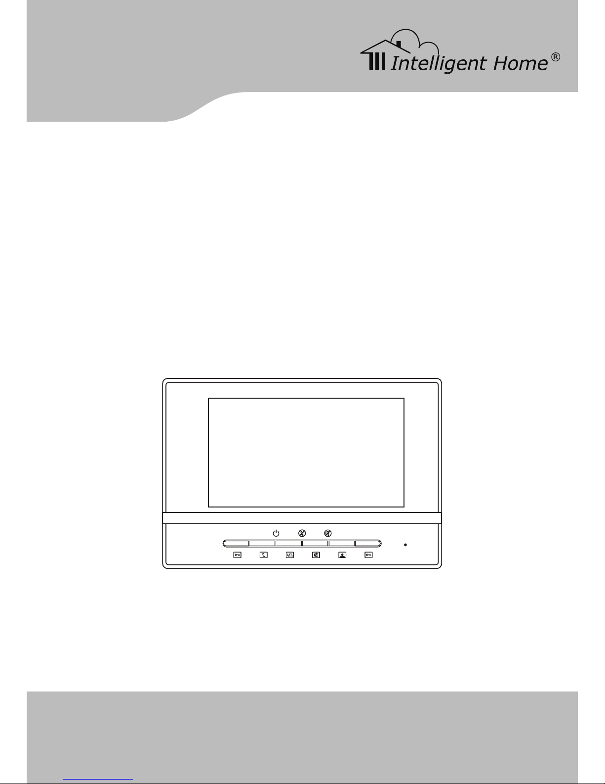
Video Door Entry System
user manual
Luna
www.intelligenthomeonline.com
CAT-5 network cable
Page 2

● Connect this unit ONLY to other compatible units. Do not connect it to
any other type of alarm or auxiliary device. Connecting anything else
to this unit may damage it or prevent it from operating properly, and will
invalidate the warranty.
● Do not place cables from the AC/DC adapters, camera or monitor where
they can be damaged or stepped on. Protect the cables by keeping
them out of the way of children, pets and routine household trafc. Do
not place heavy objects on power cables; do not cover them with rugs or
carpet.
● Unplug the AC/DC adapters from the wall outlet when the system is not
in use for a long time.
● Slots or openings in the back of the monitor, are provided for ventilation
and to ensure reliable operation of the video monitor or equipment and
to protect if from overheating. These openings must not be blocked or
covered. The monitor should never be placed near or over a radiator and
should not be placed in a built-in installation or enclosure unless proper
ventilation is provided.
● All parts should be protected from violent vibration. Impact shocks and
dropping may damage the product and should be avoided.
● Installation of doorbell camera facing into direct sunlight may affect
quality of the video.
PRECAUTIONS
Page 3

CONTENT
1. Indoor Monitor ----------------------------- 1
2A. Doorbell Camera(Model A) ------------------- 1
2B. Doorbell Camera(Model B) ------------------- 2
2C. Doorbell Camera(Model C) ------------------- 2
3. System Connection ------------------------- 4
4. 1 Doorbell and 4 Monitors Connection ------------ 5
5. 2 Doorbells and 3 Monitors Connection ----------- 6
6. Basic Video Door Phone Operation -------------- 7
7. Mute function ------------------------------ 8
8. Card and Service Button(Model C only) ----------- 8
9. Remote control(optional) ---------------------- 9
Page 4
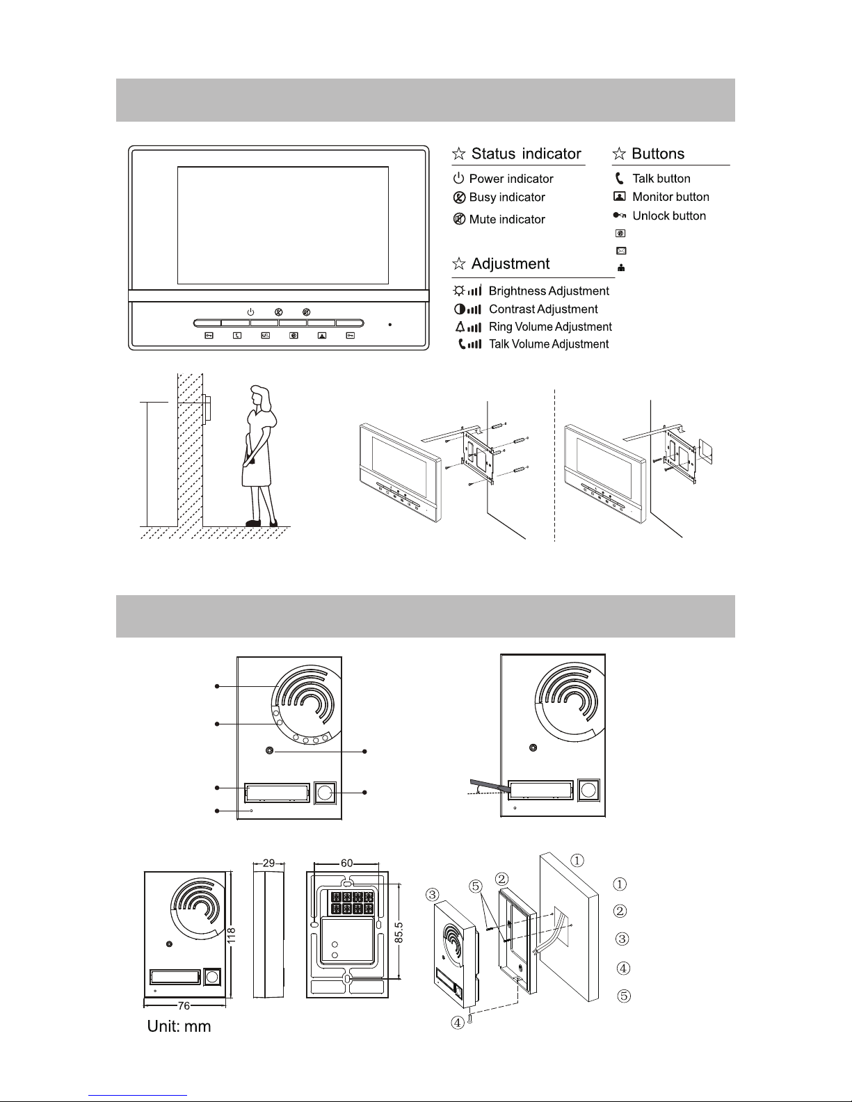
145~160 cm
The recommended installation heights for both
Monitor and Camera 145~160mm.
Direct wall mounting Mounting with 86 box
Mute button
Reserved
Reserved
Mounting panel
Door/wall
Doorbell panel
Screw
Screw
Camera Lens
Open the name tag
Call Button
Night-view LED
Speaker
Microphone
Name Tag
1. Indoor Monitor
2A. Doorbell Camera(Model A)
-1-
Page 5
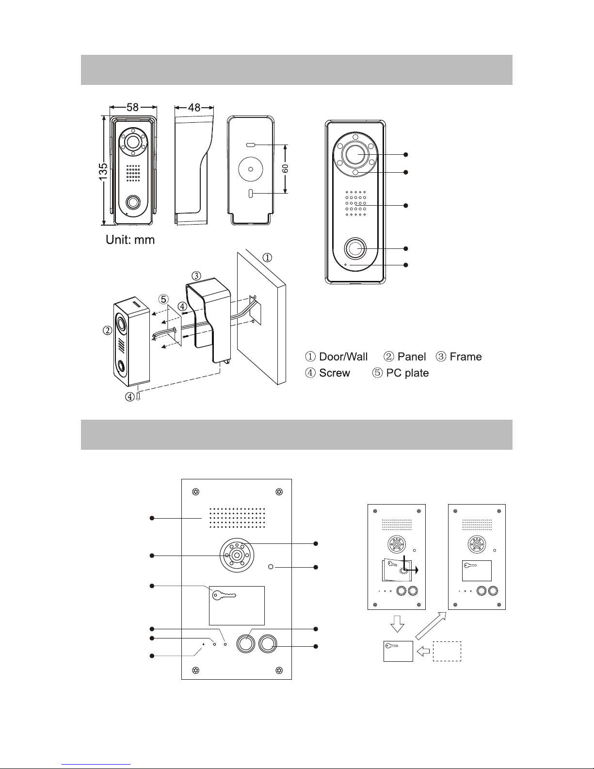
Camera Lens
Call Button
Night-view LED
Speaker
Microphone
10
SPEAK
NOW
DOOR
SERVICE
OPEN
CALL
SPEAK
NOW
DOOR
SERVICE
OPEN
CALL
10
SPEAK
NOW
DOOR
SERVICE
OPEN
CALL
Camera Lens
Call Button
Service Button
plastic tag paper
Infrared LED
How to change name tag
Infrared Sensor
Speaker
Microphone
Door opeo LED
Speak Now LED
Card reader
&Name tag
10
2B. Doorbell Camera(Model B)
2C. Doorbell Camera(Model C)
-2-
Page 6
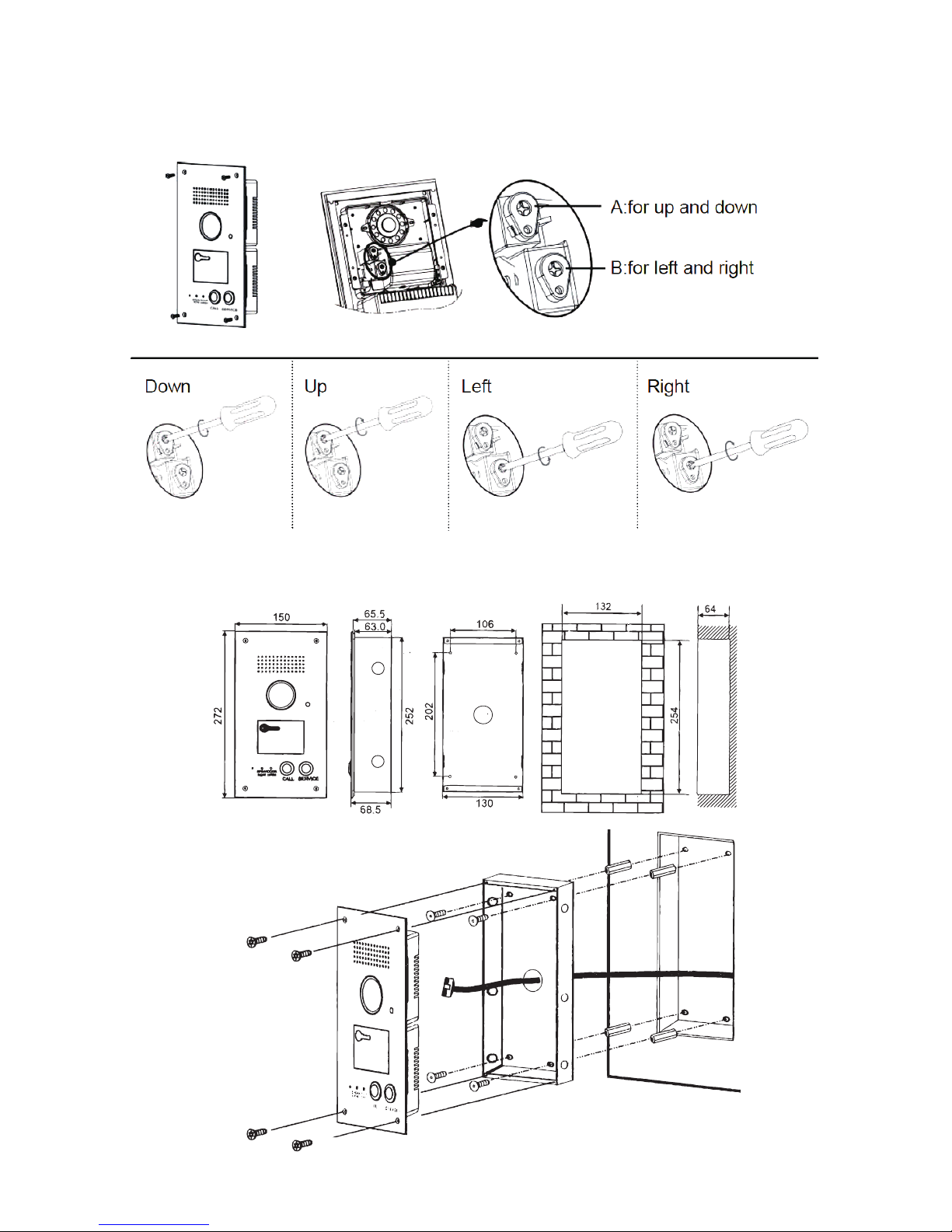
How to adjust camera angle
Mounting on the wall
-3-
Page 7

3. System Connection
CAT-5 or CAT5E cable can be used, the maximum distance from Doorbell
Camera to Monitor is 100 meters.(When over 100 meters, an extra power
supply needed to be connected to the Monitor)
● Note 1: Connect the power(+) to 8 pin and power(-) to 7 pin.
● Note 2: When there is only one Doorbell Camera and one Monitor installed, Keep the JP1
jumper; when multiple Doorbell or Monitor install, remove the JP1 jumper.
● Note 3: When connect a Normally-Open lock(Power-to-open lock), as show in the picture,
connect to the COM and NO pin; when connect a Normally-Close lock(Power-off-to-open lock),
connect to the COM and NC pin.
● Note 4: The power supply for the lock is not included in the product, please use appropriate
power supply.
● Note 5: Unlock time jumper. Can be set to 1 second or 5 seconds.
● Note 6: Function reserved.
Camera
Exit Button
+
+--
Monitor
Power
Supply
Cat-5 Cable
ON
1 ~ 8
OFF
Brown
Brown/white
Blue
Blue/white
Green
Green/white
Orange
Orange/white
JP1
Note 4
Note 1
Note 2
Note 5
Note 6
Note 3
1 2 3 4 5 6 7 8
GS INDOOR GND NO NC COM out
+12V
Power supply
12345678
8. Brown
7. Brown/white
6. Green
5. Blue/white
4. Blue
3. Green/white
2. Orange
1. Orange/white
12345678
+
-
-4-
Page 8

4. 1 Doorbell and 4 Monitors Connection
Doorbell
Camera
Doorbell Camera
Power
Supply
Distributor 4110S
Distributor 4110S
Power
Supply
1# Monitor
1# Monitor
2# Monitor
2# Monitor
3# Monitor
3# Monitor
4# Monitor
4# Monitor
Brown
PORT4
DC+
GND
AF+
AF-
VF+
VF-LBLA
PORT3
PORT2
PORT1
Brown/white
Blue
Blue/white
Green
Green/white
Orange
Orange/white
JP1
1 2 3 4 5 6 7 8
GS INDOOR GND NO NC COM out
+12V
+
-
-5-
Page 9
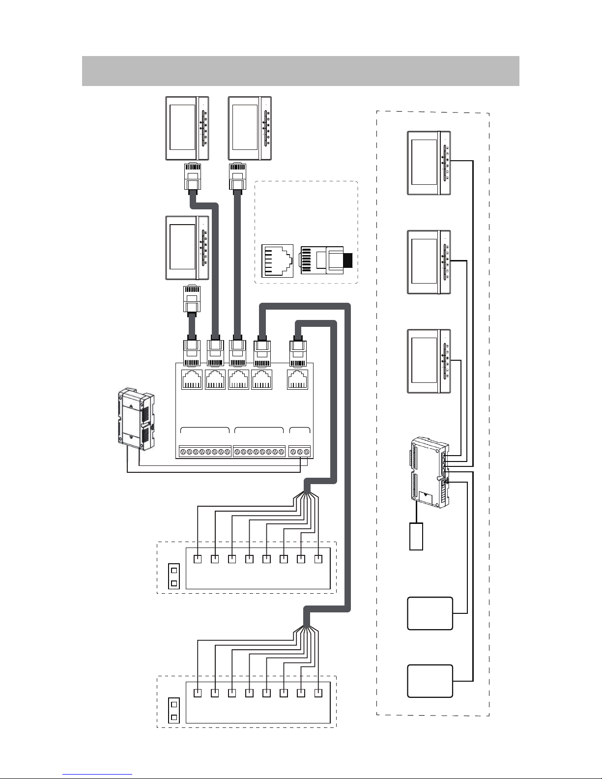
5. 2 Doorbells and 3 Monitors Connection
2# Doorbell
2# Doorbell
1# Doorbell
1# Doorbell
Power
Supply
Distributor 4230
Distributor 4230
Power
Supply
3# Monitor 2# Monitor
1# Monitor
1# Monitor
3# Monitor
2# Monitor
CH3+
CH3-
CH2+
CH2-
CH1+
CH1-LBLA
CH3+
CH3-
CH2+
CH2-
CH1+
CH1-LBLAPSGND
DC+
PORT3
PORT2
Down link
PORT1
doorbell 1
doorbell 2
JP1
1 2 3 4 5 6 7 8
JP1
1 2 3 4 5 6 7 8
+
-
12345678
8. Brown
7. Brown/white
6. Blue
5. Blue/white
4. Green
3. Green/white
2. Orange
1. Orange/white
12345678
Up linkPower
-6-
Page 10
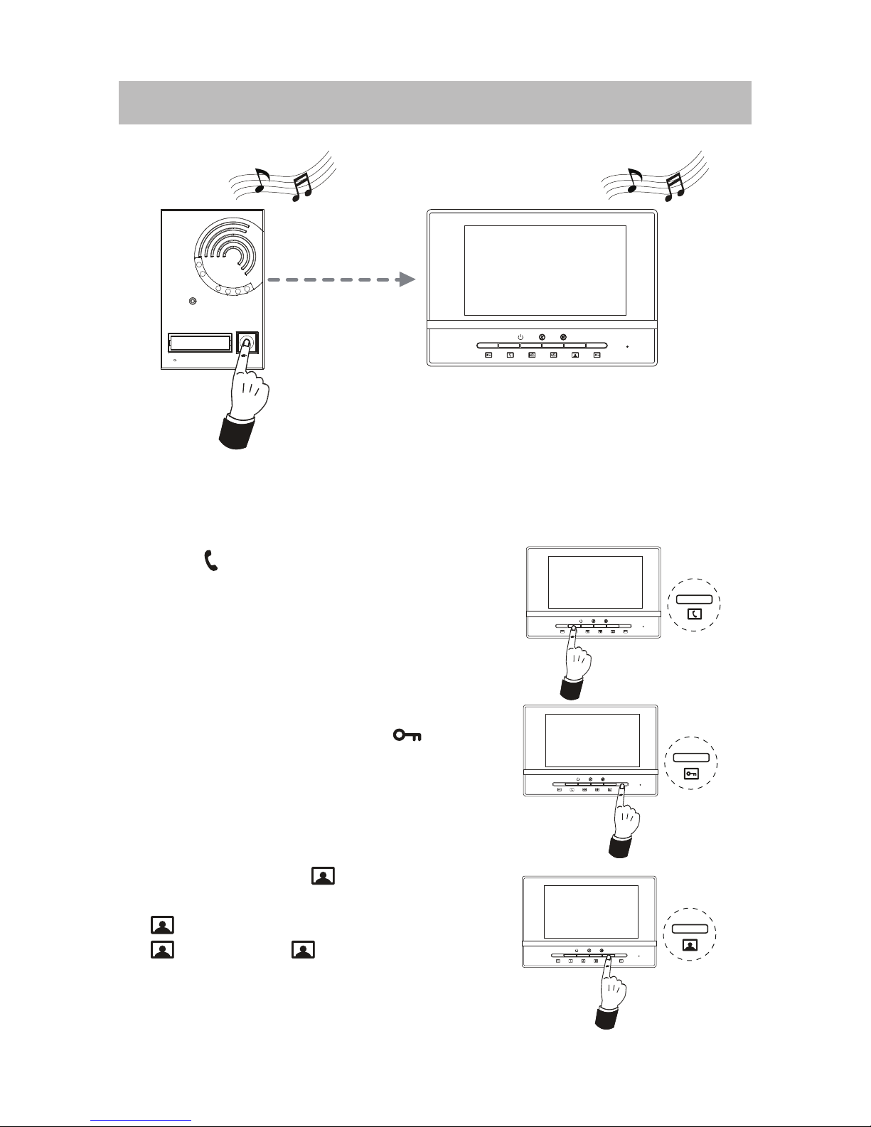
1. When visitor presses the Call Button on the Outdoor Station, the
monitor rings, at the same time, the screen displays the visitor image,
and MESG LED turns to red.
2. Press
Button to talk to the visitor(If there is
no anwer, the system will automatically reset
to standby state after 60 seconds); Press
Button again to end the conversation(or the
conversation will be cut off automatically after
120 seconds).
TALK Button
Unlock Button
Monitor Button
3. During ringing or talking, press Button to
unlock the door. (A Di~ sound will prompt to
indicate the door is opened)
4. In standby, press
Button to monitor
outside. If two doorbells were installed, press
Button shows view of Doorbell 1, press
to end; press one more time to view
Doorbell 2. (Monitoring time is limited to 60
seconds)
6. Basic Video Door Phone Operation
-7-
Page 11

SERVI
1. When you do not want to be disturbed
by any calling, you can turn on the mute
function.
2. Adjust the
[Ring Volume
Adjustment] to the lowest, the ring will
be completely turned off, and the
indicator will be turned on.
● Card: Put the registered card on the card reader (if there is) to release the door.
● SERVICE Button: In the authorized time, press SERVICE button on the doorbell to release
the door. This button is special for postmen or other service people. The function has to be
programmed by the remote control. See next section for remote control details.
7. Mute function
8. Card and Service Button(Model C only)
Mute button
-8-
Page 12

9. Remote control(optional)
1. Key panel discriptions
2. Remarks functions
-9-
Page 13
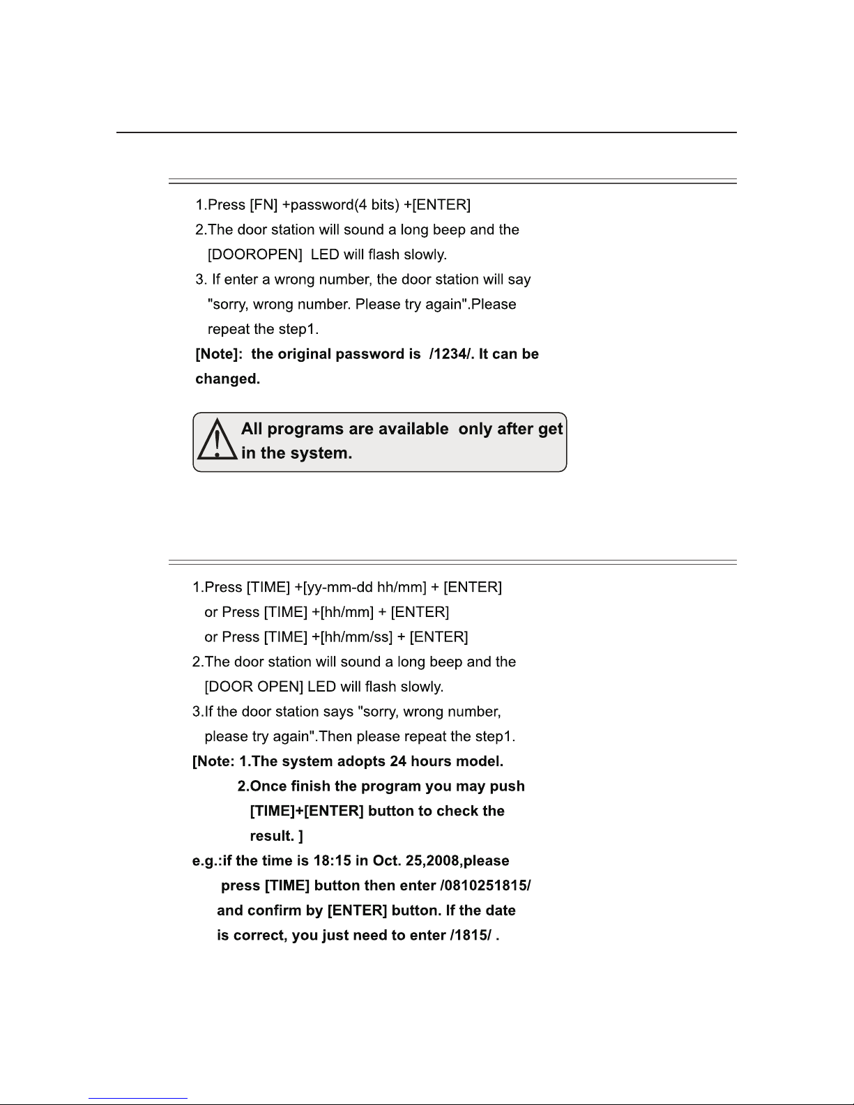
3. Programming
3.1 Get into the system
3.2 Date and time
-10-
Page 14

3.3 SERVICE Button
-11-
Page 15

3.4 Card
-12-
Page 16
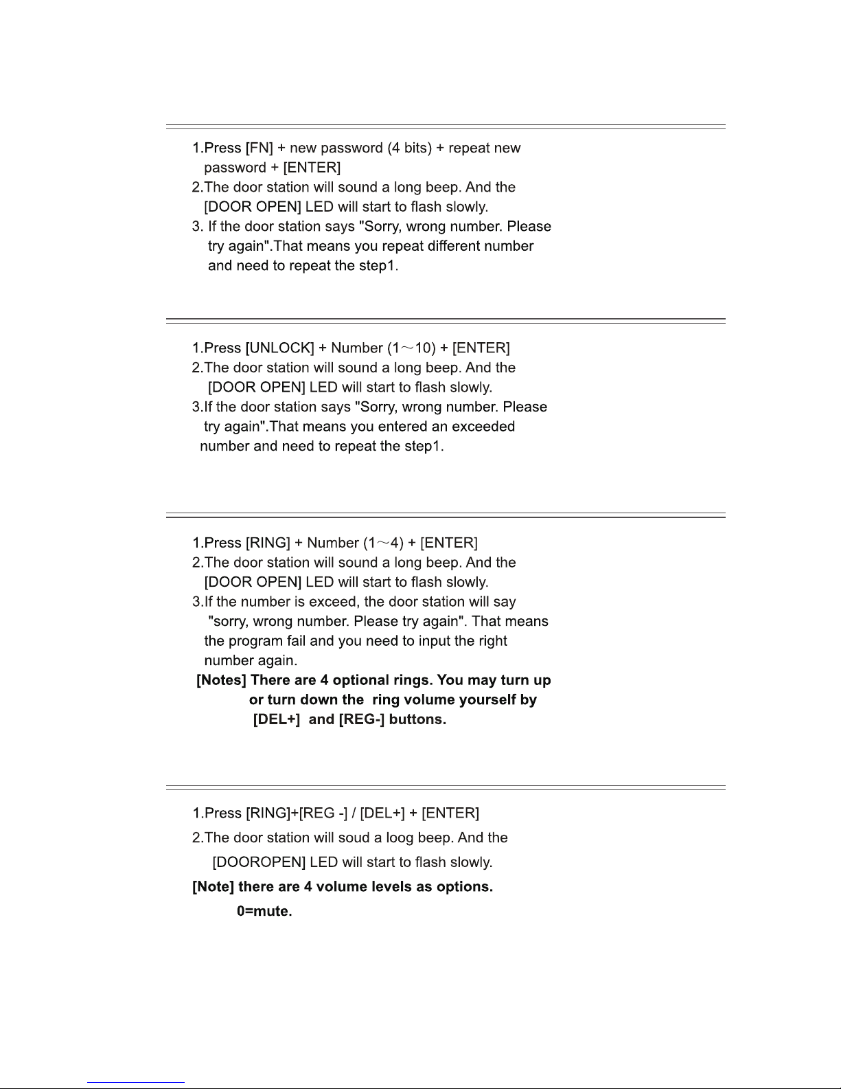
3.5 Change password
3.6 Unlock time
3.7 Ring type
3.8 Ring volume
-13-
Page 17
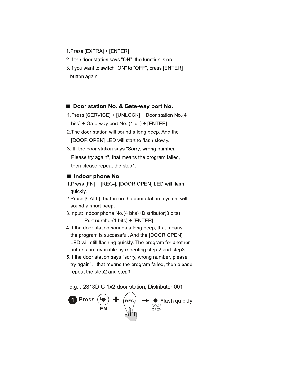
3.9 Door alarm settings (for direct call doorbell only)
3.9 Network system congure (for direct call doorbell only)
-14-
Page 18
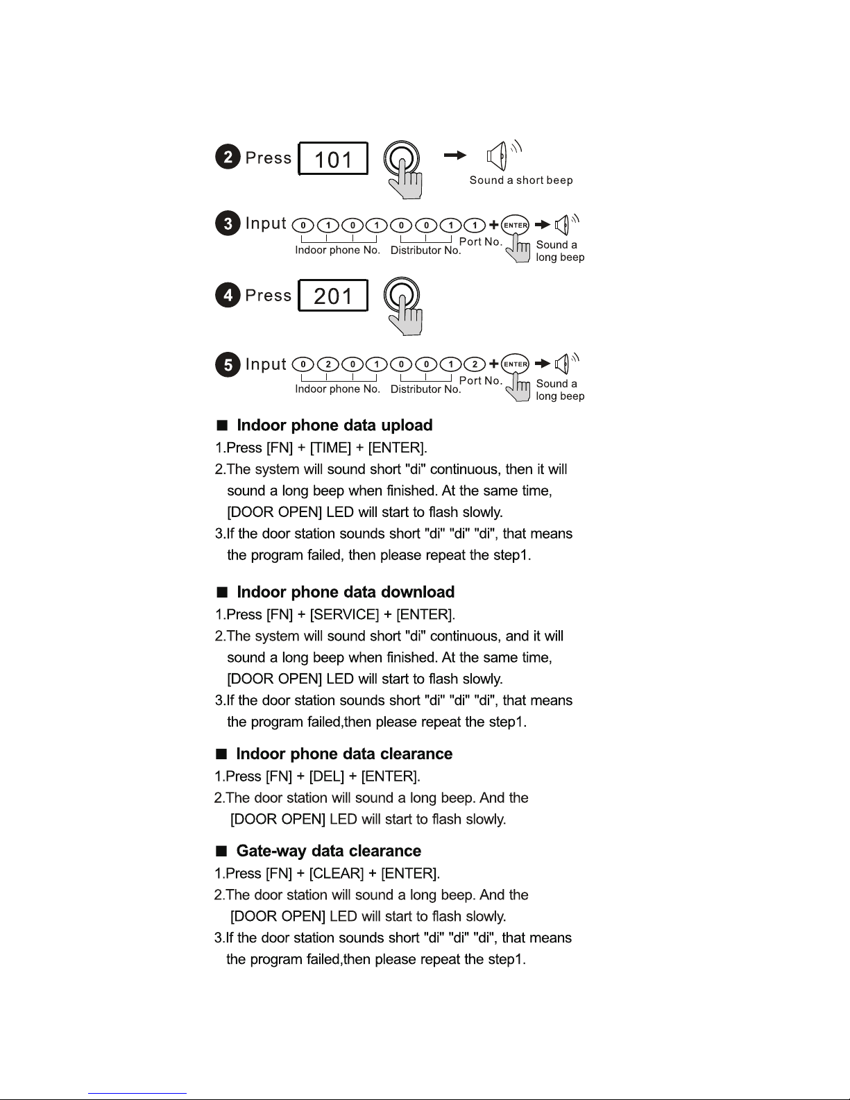
-15-
Page 19

WARRANTY CARD
NB Please keep this document safe, as it is proof of your Warranty
Your Video door system comes with a one year Manufacturers Warranty. When
used normally, the following services are offered:
1. Replacement for malfunctioning parts in rst three months
2. Repair free of charge for malfunctioning parts in rst year
The following actions will void the Warranty:
1. Damage to the device during installation
2. Damage to the device through misuse
3. Opening and/or disassembling the device
4. Attempting to force the device to perform functions for which it is not intended
5. Attaching the device to power supplies other than thoserecommended by the
manufacturer
Distributor for Warranty purposes:
Intelligent Home Online Ltd
34a High Street, Hornsey, London, N87NX
+44 (0)20 83482040
www.intelligenthomeonline.com
Product:_____________________________________________
Purchaser Name: ______________________________________
Invoice N: ____________________________________________
Purchase Date_________________________________________
Page 20

www.intelligenthomeonline.com
The design and specications can be changed without notice to the user.
Right to interpret and copyright of this manual are preserved.
Luna-CAT5-V1 2011-02-16
 Loading...