


Door Station DT591/592
2-wire series
DT591 DT592
www.intelligenthomeonline.com

CONTENTS

1.Parts and Functions
Rain Cover
2.Terminal Descriptions
1 2 3
ON
MIC adjustment
SPK adjustment
1 2
BUS
PL
S1+S2+S-
Lock Control Jumper
Doorstation Code DIP
Main Connect Port
176 mm
90 mm
23 mm
Speaker
Nameplate
Call Button
Microphone
Camera Lens
Night Viision LED
DT592 with 2-call buttons shown
- 1-
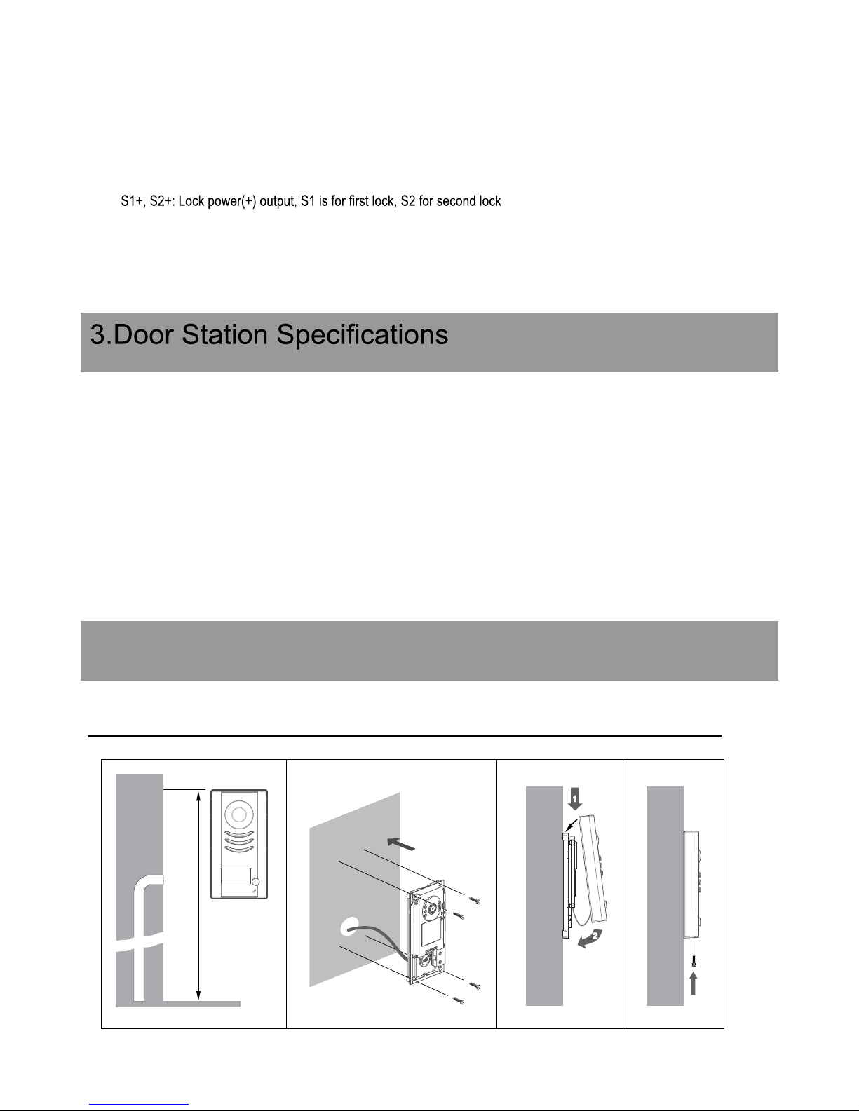
4.Mounting
160-165cm
1 2
1
2
3 4
•Lock Control Jumper: Keep or remove the Jumper for different types of electric locks- see 5.2.1 , 5.2.2
•Doorstation Code DIP switches: To set the address for multiple door stations -see 6.1
•Main Connect Port: To connect the bus line and the electric locks
• BUS: Connect to the bus line, NO POLARITY
• PL: External lock power input, connect to the power positive (power +)
•
• S-: Lock power(-) output, connect to the power(-) input of locks only when locks are powered via Door Station
Resolution: > 450 TV Lines
Night Vision: 0.1LUX with white LED
Lock Power supply:
12Vdc, 300mA (Internal Power)
Power Consumption:
1W in standby, 12W in working
NO, COM dry contact: Max. 48V dc 1.5A
Unlocking time:
1 to 9 sec, set by Video Monitor
Working temperature: -10ºC ~ 45ºC
4.1 Mounting Without Rain Cover
- 2-

1
160-165cm
2
1
2
3 4
name label
4.2 Mounting With Rain Cover
4.3 Placing Name Label
Move the plastic cover away to open the transparent name label cover, insert a paper, then put the plastic cover back
- 3-

5.System Wiring and Connections
L1 L2 PL S1+ S2+ S-
-
+
DPS PS4
monitor
4.4 Adjusting Camera Angle
5.1 Basic Connection
use a screwdriver to loosen the screw and then adjust the angle
AC~
- 4-
BUS(IM) BUS(DS)
PC6
AC~
monitor
-
+
12
ON
L1 L2 PL S1+ S2+ S-

BUS PL S1+ S2+ S-
EB
EB
-
+
-
+
lock #2
lock #1
BUS PL S1+ S2+ S-
EB
-
+
5.2 Electric Lock Connection
5.2.1 Electric Power-on-to-open lock powered by the system
1. Only Power-on-to-open electric locks can be connected
2. The lock is limited to 12V, and holding current must be not more than 250mA
3. The door lock control is not timed when Exit Button used
4. The Unlock Mode parameter must be set to 0 (default) via Video Monitor
connect one lock connect two locks
1 2 3
Jumper position in 1-2
5.2.2 Magnetic Power-off-to-open lock
1. The external power supply must be used according to the lock specications
2. The inside relay contact is restricted to AC or DC 24V/3A
3. The jumper must be taken off
4. The Unlock Mode paramenter must be set to Mode 1 via Video Monitor
- 5-
1 2 3
Jumper position in 1-2

Unlock Mode parameter and Unlocking time must be set according to the connected lock:
Mode 0 for Power-on-to-open locks
Mode 1 for Power-off-to open electric, and all magnetic locks
Connect the whole system including the lock, and power it up.
On any of video monitor touch “About” or “Intelligent Home” icon. Page with software info will open
Touch and hold screen and then go to “Installer Setup”
Using digital keypad, type in:
8010 # for Mode 0 (Power-on-to-open locks)
8011 # for Mode 1 (Power-off-to-open electric and all magnetic locks)
Next step, set the Unlocking time
Using digital keypad, type in:
8020# unlocking time set to 0 sec
8021# 1 sec
8022# 2 sec
8023# 3 sec
8024# 4 sec
8025# unlocking time set to 5 sec
8026# 6 sec
8027# 7 sec
8028# 8 sec
8029# unlocking time set to 9 sec (maximum)
-
1 2 3
Take off the Jumper
BUS PL S1+ S2+ S-
+
Power supply Power supply
1 2 3
Take off the Jumper
+
-
-
BUS PL S1+ S2+ S-
+
+
-
+
-
lock #2
lock #1
connect one lock connect two locks
5.2.3 Unlock Mode parameter and Unlocking time
- 6 -

-7-
5.3 Multi Doorstations Connection
85~260VAC
DPS
PS5
monitors
12
ON
L1 L2 PL S1+ S2+ S-
12
ON
L1 L2 PL S1+ S2+ S-
12
ON
L1 L2 PL S1+ S2+ S-
12
ON
L1 L2 PL S1+ S2+ S-
1 2
ON
1 2
ON
1 2
ON
1 2
ON
1# Camera
DIP=on,off,off
ID=00
ID=10
ID=01ID=11
2# Camera3# Camera4# Camera
DBC-4S
A B C D
OFF
ON
Impedance
switch

ON
1 2 3 4 5 6
Code=15, DIP-6=on
ON
1 2 3 4 5 6
Code=14, DIP-6=off
ON
1 2 3 4 5 6
Code=0, DIP-6=off
DPS
monitor
monitor
monitor
PS5
ID=00
ON
1 2
85~260AC
5.4 Multi Monitors Connection
5.4.1 Basic Daisy Chain Connection
- 8 -

-9-
Code=15, DIP-6=on
Code=13, DIP-6=on
Code=14, DIP-6=on
Code=12, DIP-6=on
1 2 3 4 5 6
ON
1 2 3 4 5 6
ON
Code=3, DIP-6=on
Code=1, DIP-6=on
1 2 3 4 5 6
ON
1 2 3 4 5 6
ON
Code=2, DIP-6=on
Code=0, DIP-6=on
1 2 3 4 5 6
ON
1 2 3 4 5 6
ON
1 2 3 4 5 6
ON
1 2 3 4 5 6
ON
OFF ON
OFF ON
monitor
monitor
monitor
monitor
monitor
monitor
monitor
monitor
85~260AC
DPS
PS5
ID=00
1 2
ON
DBC-4S
A B C D
DBC-4S
A B C D
Impedance
switch
Impedance
switch
DIP=on,off,off
DIP=on,off,off
5.4.2 Star Connection with DBC-4S distributors

6. Setup via DIP switches
ON(1)
ON
=
OFF(0)
ON
=
6.1 DIP Switches Settings of Single and Multiple Doorstations
6.2 DIP Switches Settings of Video Monitors
Use Tables on page 11 for programming monitor User Codes
DIP switch 6 is END of LINE switch, which have to be set ON if the Monitor is in the end of the line (bus), otherwise set OFF
-10-
Dip state Door Station ID
ID = 1(10) for the second Door Station
ID = 2(01) for the third Door Station
ID = 3(11) for the fourth Door Station
Dip state Setting Dip state Setting
The monitor is
not at the end
of the line
The monitor is
at the end of
the line
1
2
ON
1 2
ON
1 2
ON
1 2
ON
1 2 3 4 5 6
ON
1 2 3 4 5 6
ON
OFF
ON

-11-
Bit state User Code Bit state User Code Bit state User Code
Code=0 Code=11 Code=22
Code=1 Code=12
1 2 3 4 5 6
ON
Code=23
Code=2 Code=13
1 2 3 4 5 6
ON
Code=24
Code=3 Code=14
1 2 3 4 5 6
ON
Code=25
Code=4 Code=15
1 2 3 4 5 6
ON
Code=26
Code=5 Code=16
1 2 3 4 5 6
ON
Code=27
Code=6 Code=17
1 2 3 4 5 6
ON
Code=28
Code=7 Code=18
1 2 3 4 5 6
ON
Code=29
Code=8 Code=19
1 2 3 4 5 6
ON
Code=30
Code=9 Code=20
1 2 3 4 5 6
ON
Code=31
Code=10 Code=21
Button A will call Video Monitors with User Codes 0 -15
Button B will call Video Monitors with User Codes 16 to 31
A
B
A
DIP switches 1-5 are used to give unique address - USER CODE to each video monitor in the system.
1 2 3 4 5 6
ON
1 2 3 4 5 6
ON
1 2 3 4 5 6
ON
1 2 3 4 5 6
ON
1 2 3 4 5 6
ON
1 2 3 4 5 6
ON
1 2 3 4 5 6
ON
1 2 3 4 5 6
ON
1 2 3 4 5 6
ON
1 2 3 4 5 6
ON
1 2 3 4 5 6
ON
1 2 3 4 5 6
ON
1 2 3 4 5 6
ON
1 2 3 4 5 6
ON
1 2 3 4 5 6
ON
1 2 3 4 5 6
ON
1 2 3 4 5 6
ON
1 2 3 4 5 6
ON
1 2 3 4 5 6
ON
1 2 3 4 5 6
ON
1 2 3 4 5 6
ON
1 2 3 4 5 6
ON
1 2 3 4 5 6
ON
USER CODE TABLE

7.Cable Requirements
monitor
two or four monitors
Monitors quantity < 20
Cable Usage
Twisted pair 2 x 0.75 mm
2
Twisted pair 2 x 1 mm
2
A
60
150
B
60
150
Monitors quantity > 20
Cable Usage
Twisted pair 2 x 1 mm
2
Twisted pair 2 x 1.5 mm
2
A
70
100
B
70
100
C
60
100
C
70
100
The furthest monitor
monitor
monitor
C
DPS
PS5
DBC-4S
B
A
This system transmits video and audio through the power cable. No Polarity connection
• Recommended cables: twisted pair, power ex multi-cores, speaker cable, CAT5/CAT6
• Minimum requirements 0.5mm cable up to 2mm (depends on distance)
-12-

-13-
WARRANTY CARD
NB Please keep this document safe, as it is proof of your Warranty
Your Video door system comes with a one year Manufacturers Warranty. When
used normally, the following services are offered:
The following actions will void the Warranty:
1. Damage to the device during installation
2. Damage to the device through misuse
3. Opening and/or disassembling the device
4. Attempting to force the device to perform functions for which it is not intended
5. Attaching the device to power supplies other than thoserecommended by the
manufacturer
Distributor for Warranty purposes:
Intelligent Home Online Ltd
62 Hartley Old Road
Purley
Surrey
CR8 4HJ
+44 (0)20 86170015
www.intelligenthomeonline.com
Product:_____________________________________________
Serial Number:_________________________________________
Invoice N: ____________________________________________
Purchase Date_________________________________________

www.intelligenthomeonline.com
The design and specications can be changed without notice to the user.
Right to interpret and copyright of this manual are preserved.
D
 Loading...