

Page 1
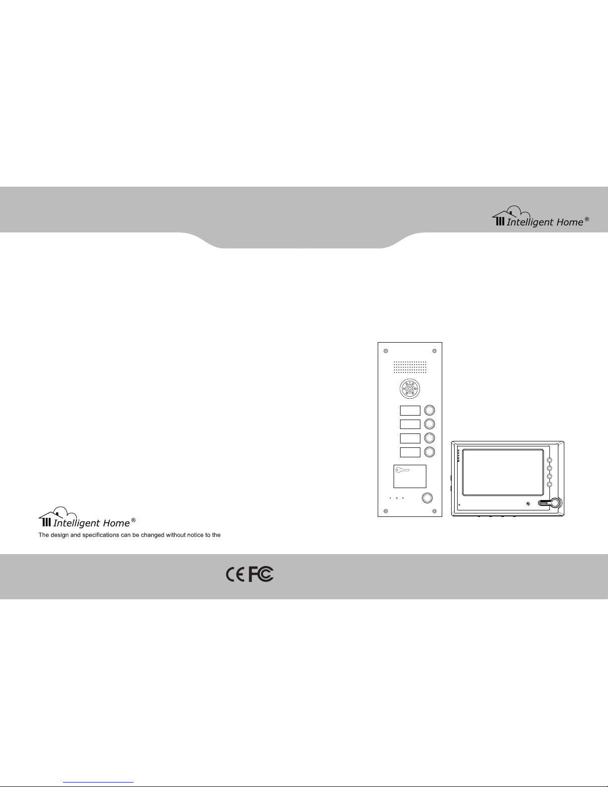
Video Door Entry System
for Flats / Aprtments
user manual
Cat-5 network cable
www.intelligenthomeonline.comwww.intelligenthomeonline.com
user. Right to interpret and copyright of this manual are preserved.
101
201
301
401
10
SPEAK
NOW
DOOR
SERVICE
OPEN
Page 2
WARRANTY CARD
NB Please keep this document safe, as it is proof of your Warranty
Your Video door system comes with a one year Manufacturers Warranty. When
used normally, the following services are offered:
The following actions will void the Warranty:
1. Damage to the device during installation
2. Damage to the device through misuse
3. Opening and/or disassembling the device
4. Attempting to force the device to perform functions for which it is not intended
5. Attaching the device to power supplies other than thoserecommended by the
manufacturer
Distributor for Warranty purposes:
Lale Trading Ltd
34a High Street
Hornsey
London
N87NX
+44 (0)20 83482040
www.intelligenthomeonline.com
Product:_____________________________________________
Purchaser Name: ______________________________________
Invoice N: ____________________________________________
Purchase Date_________________________________________
Page 3

55
■ Register patrol card
Press [CLR]→ Card number→ [F3].
■ Delete single card
Card number delete:
Press[CLR]→Card num ber→ [F4].
Card reader delete:
Press[CLR]→[ F9]→ put the cards close to the card reader in turn→ [CLR].
■ Delete all cards
Press [CLR] → Password → [F6], card reader status LED blinks c ontinuously. And it return to be on after delete all the cards, the
device will sound a long beep at the same time.
■ Register device number
Press[CLR]→Door station number(4 bits)→[F7].
Contents
1 System brief introduction................................ ............................................................................................................................... 1
System introduction ................................................................................................... .............................................................. 1
System features................... ............................................................................. ....................................................................... 1
System function .................................................................................................. ..................................................................... 1
Components......................................................................................... .................................................................................... 2
2 System wiring diagram................................ ................................................................................................................................ ..4
3 Product wiring diagram................................................................ .................................................................................................. 6
Connection explanation .................................................................................................... .......................................................6
Switch wiring diagram................................ .............................................................................................................................. 7
Gate-way wiring diagram ............................................................................................................................... ..........................8
Distributor wiring diagram ...................................................................................................................................... ..................9
Multiple door stations(extension)wiring map...................... .................................................................................................... 10
Door station electric lock wring diagram ...................................................................................................... ..........................11
4 System programming................... .................................................................................................................... ........................... 12
Building programming................................ ............................................................................................................................ 12
Network system programming ............................................................................................................................... ................23
5 Project case ................................................................................................................................ ............................................... 28
Customer requirement description................................ ......................................................................................................... 28
Components......................................................................................... .................................................................................. 28
System wiring diagram...................................................... ..................................................................................................... 29
System Programming .......................................................................................... .................................................................. 30
6 Product installation explanation............................................................................... ................................................................... 33
Door station installation................................................................ .......................................................................................... 33
UPS power supply installation............................................................................................. ...................................................33
Switch power, distributor, gate-way installation.............................. ........................................................................................ 34
7 Trouble shooting ................................................................................................................. ....................................................... 35
Appendix 1. LCD door station operation explanation ........................................................................................................... ..........36
Appendix 2. LED door station operation explanation.......................................................................................................... ............43
Appendix 3. Perimeter gate station operation explanation ............................................................................................................. 48
Appendix 4. RJ45 plug making method.................................................................... ...................................................................... 52
Appendix 5. Remote control user manual ........................................................................................................ .............................. 54
Page 4
1
1. System brief introduction
Systemintroduction
C-5 system uses category 5 cable to transfer signal, it is very easy for system installation and maintenance. It adopts the automatic
video pre-amplified and loss compensation technology to enable the stables ignaltransmission , this strength is more obvious in the long
distance transmission, the image will be still clear and preventative fromd isturbance. Besides, the C5 system integrates the functions of
network video intercom, alarm and message sending & receiving, which can cater to any of your needs.
System features
■Hig hsafety. Antistatic and anti thunder design.
■Sup ercompatibility. All of the door stations and indoor phones can work with each other as you wish.
■Hig h reliability. Door station and indoor phone are controlled by MCUto make system much safer and more reliable.
■Eas ys etting.System parameter set by computer, alarm information can be recorded and checked, very convenient to use.
■Sim ple wiring. Using standard CAT-5 cable for connection, high reliability, and convenience for installation and maintenance.
System function
■ Intercom
The system supports video intercom between door station and in door phone, door station and guard unit, perimeter gate station and
guard unit, perimeter gate station and indoor phone, guard unit and indoor phone. if the product is only audio available, there can only
audio intercom between above mentioned components.
■ Monitor
Indoor phone can monitor door station and second confirmed door station. Guard u nit can monitor door station and perimeter gate
station.
[Note] Onlyvideo system hasthisfunction.
■ Doorrelease
Several ways for door release: It can be from indoor phone or guard unit to unlock, or by password or IC/ID card etc to unlock.
■Alarm
Indoor phone can send alarm signal to guard unit
[Note] Belowfunctions only apply to indoorphonewith alarm area
Alarm message can be sent to guard unit automatically, and guard unit can check the alarm types, time, place and resident information
through the remote computer control.
■ Picturememory
Can record and check the image of visitors
[Note] Only applytothe indoor phone with picturememoryfunction.
54
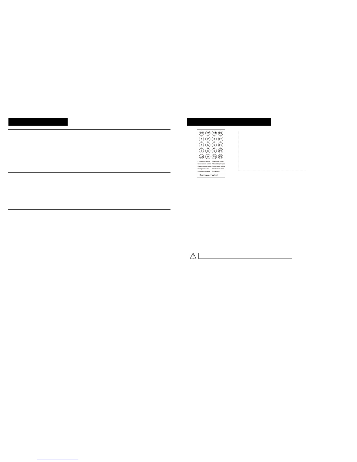
Appendix 5. Remote control usermanual
■ Change password
1. Press [CLR]→ current password(4bits)→ new password(4bits)→ [F3].
2. The Card Reader status LED will blink once, and the device will sound a long "di";
3. If enter a wrong number, the Card Reader status LED will blink thrice quickly, and the device will sound three short "di", please
repeat the step1.
[Note]The originalpassword is 1-2-3-4.
Enter the setting state
1. Press [CLR]→ Password(4bits)→ [F3].
2. The Card Reader status LED will on, and the device will sound a long "di";
3. If enter a wrong number, the Card Reader statusL ED will blink thrice quickly, and the device will sound three short "di", please
repeat the step1.
[Note]Press [CLR]→ [F3] can quit the setting state.
■ Unlock time
Press [CLR]→ Unlock time (01~20)→ [F3].
[Note] Original factory settingis5s.
e.g. Press [CLR]→ [0][8]→ [F3],to set theunlocktime 8s.
■ Register single card
Card number register:
Press[CLR]→ Card number→ [F1].
Card reader register:
Press[CLR]→ [F8]→ put the cards close to the card reader in turn→ [CLR].
e.g. press[CLR]→ [02584235]→ [F1].
or press[CLR]→ [F8]→ first card→ second card→ … … → [CLR].
Hereinafter settings
are available only after enter the setting state.
Specifications:
Battery: 3V (CR2025)
Available distance: ≤1 meters
Angle: ≤30°
※ Remarks function
1.If enter wrong number, please press [CLR] button to
delete the wrong one.
Page 5
53
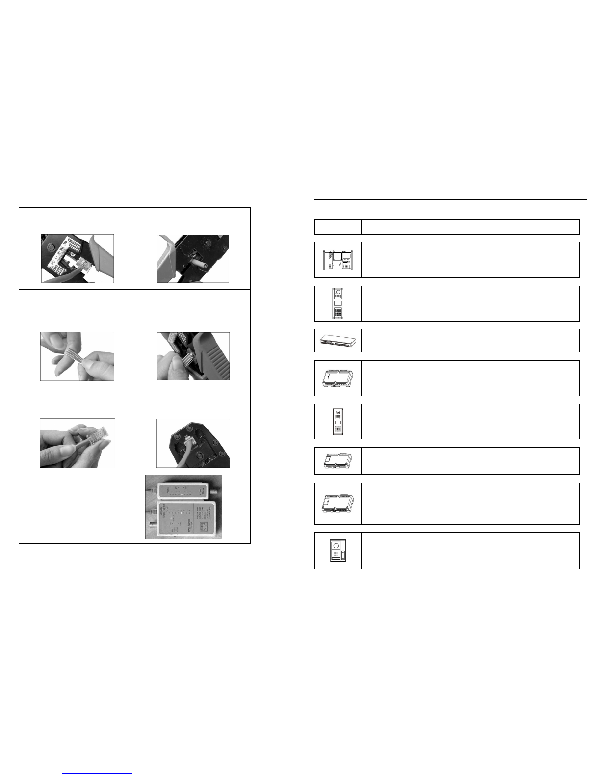
RJ45 plug making step pictures
Step 1. Use clamp’s knife edge to cut needed length of
the cable.
Step 2. Remove the grey rubber protector, use knife
edge to cut the cable trim
Step 3 .:Untie the twisted lines,follow the sequence
from left to right (orange white-orange-green white-
blue-blue white - green-brown white-brown) to
arrange the lines,make them straight and clean.
Step 4. : Use clamp knife edge to cut the top of the
lines clean,the remained parts without rubber should
be around 15mm.
Step 5 :Insert the readyli nesinto plug according to the
picture (Note: The plug with spring s hould face
down.)and make sure that the lines areto the top of
the plug
Step 6 :Pressing plug. After making sure the lines’
sequence is correct, put the plug into the 8 P groove,
press the clamp to make the needle outside of plug
into plug.
Step 7: repeat Step 1 - Step 6 for another end of the
cable.
Step 8: use the tester to test if the wires at two ends are
conjoint well and corresponding each other at right
sequence.
2
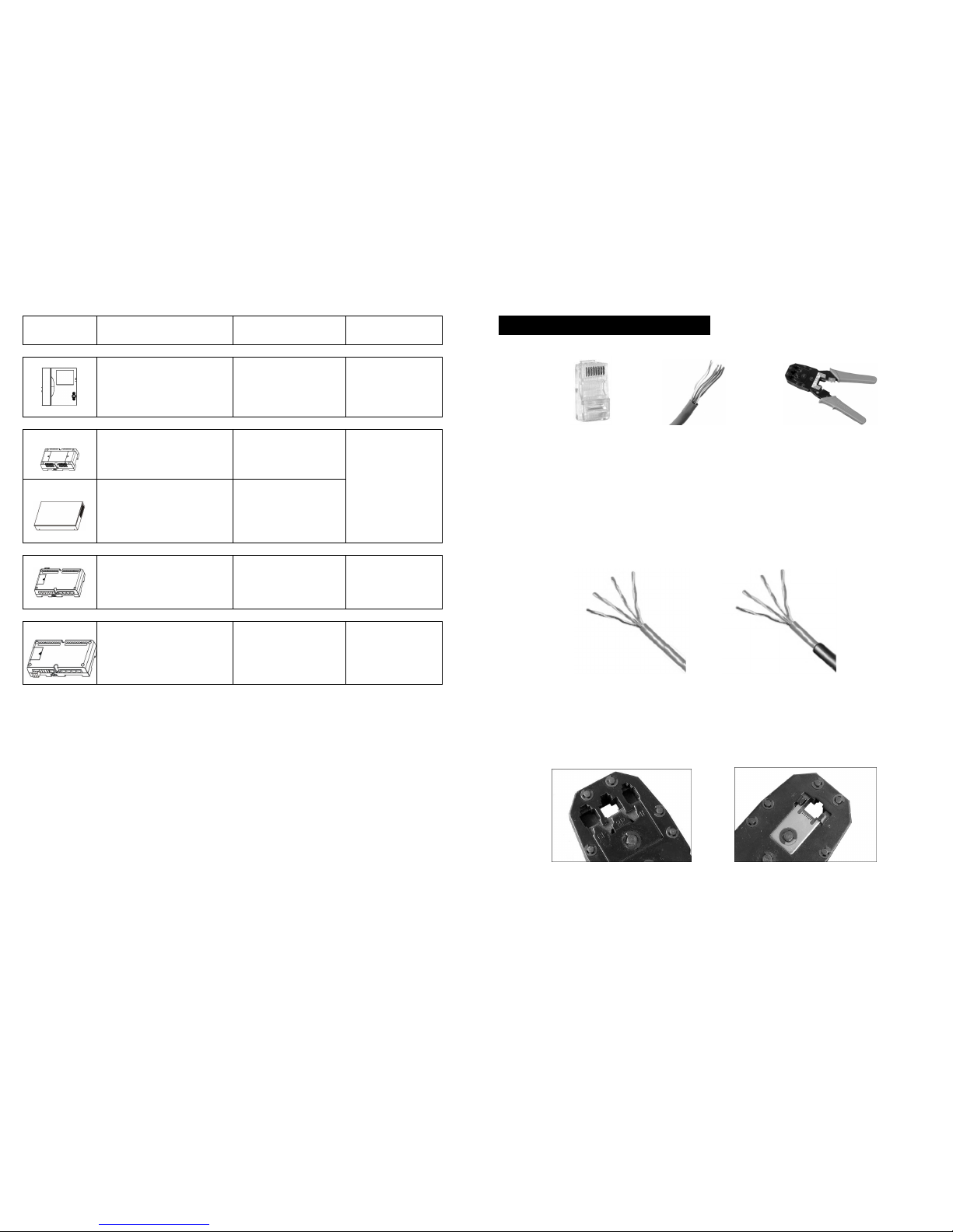
Components (Pictures in the table only for reference.)
Product Main features specifications Remark
Guard unit
Remote monitor any door station in
network, intercom between all indoor
phones and door stations, store and
review alarm information.
Operating voltage: DC30~35V;
Quiescent current: ≤ 90mA;
Operating current: ≤ 350mA
Network equipments
(optional)
Perimeter gate station
Using at main entrance, with the
intercom, door release and other
functions.
Operating voltage: DC30~35V;
Quiescent current: ≤ 90mA;
Operating current: ≤ 260mA
Network equipments
(optional)
Network switch
Achieve the function of switching signal
among every branch.
Operating voltage: DC30~35V;
Quiescent current: ≤180mA;
Operating current: ≤ 200mA
Network equipment (basic)
Gate-way
Achieve the function of audio and video
signal switch function.
Operating voltage: DC30~35V;
Quiescent current: ≤ 30mA;
Operating current: ≤ 90mA
Network equipment (basic)
Door station
Using at building entrance, with the
intercom, door release and other
functions.
Operating voltage: DC30~35V;
Quiescent current: ≤ 90mA;
Operating current: ≤ 250mA
Unit equipment (basic)
Distributor
Achieve the function of audio, video
signal distribution , each distributor can
connect up to 4 indoor phones in
different apartment.
Operating voltage: DC30~35V;
Quiescent current: ≤ 15mA;
Operating current: ≤ 90mA
Unit equipment (basic)
Apartment distributor( with second confirmed door station)
Achieve the function of audio, video
signal distribution , each distributor can
connect up to 4 indoor phones in the
same apartment. When calling, 4 indoor
phones will ring at the same time
Operating voltage: DC30~35V;
Quiescent current: ≤ 15mA;
Operating current: ≤ 90mA
Unit equipment (optional),
match with apartment door
station in use
Apartment second confirmed door station
Used in front of apartment door.
Operating voltage: DC30~35V;
Quiescent current: ≤ 90mA;
Operating current: ≤ 250mA
Unit equipment (optional),
only one for each family,
use together with single
channel distributor(with
second confirmed door
station port)
Page 6
3
Product Main features Specifications Remark
Indoor phone
Achieve the functions of intercom,
unlock, monitor, and sending alarm to
guard unit
Operating voltage: DC30~35V;
Quiescent current: ≤ 25mA;
Operating current: ≤ 350mA
Unit equipment(basic)
One family can have 1 -4
pcs of indoor phone
Power supply
Switch power supply
Supply power for equipment(not including
battery)
Operating voltage:AC180~270V
50~60Hz;
DC Output: DC35V/1.4A;
System equipment(basic)
User can choose power supply
according to their actualneed
UPS power supply
Supply power for equipment.(The power is
with battery backup inside.)
Operating voltage:AC180~270V
50~60Hz;
DC Output: DC35V/1.4A; backup
battery capacity: 4Ah
Video repeater
Used to improve long distancenetwork video
effect
Operating voltage: DC30~35V;
Operating current:≤ 60mA
It is used when the network
distance in a unit surpasses
600m.
Door station extender
Used for extend the accessory door
station.
Operating voltage: DC30~35V;
Quiescent current:≤ 15mA
Operating current:≤ 60mA
Unit equipment (optional)
52
Appendix 4. RJ45 plug making method
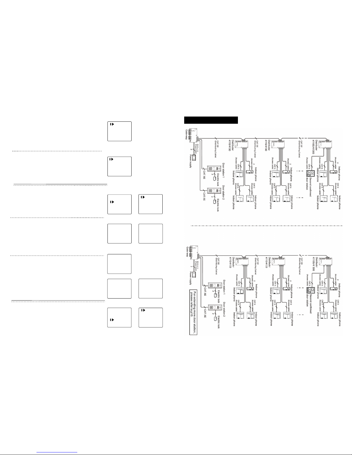
Firstly, introduce some tools and materials needed for making RJ45 plug.
RJ45 plug CAT-5 Clamp
■RJ4 5 plug
RJ45 Plug isthe connector of CAT-5 with modulejack structure. There are 8grooves on the front of theconnector called 8P(Position), and thereare 8
metal contact points called 8C(Contact). Whenconnecting CAT-5, them etal thorn shouldstab intothe cable, making metalthorn connecting with cable
‘s copper conductor tom ake the system works
■CAT 5 cable
C-5 system adopts currently widely used Category 5 cable and Category 5E cable. Meanwhile, network wiring should adopt water proof Category 5E
cable. To distinguish C-5 cableand C-5E cable, please refer to belowpicture.
C-5 water proof C-5E
■Cla mp
On top of clamp is RJ45 plug groove used for binding plug and cable together, there are three size grooves, respectively are 6P, 8P and 4P. The 8P
groove is what we use for binding RJ 45 plug. Behind 8P grooves, we can see dentate modules, which are used for pressing 8 plug contact points to
cable
Page 7
51
Door Station4
Indoor Phone4
8 bits Current
■Indoor phone digit setting
[Note] This information is used for setting the digit length of indoor
phone when perimetergatestation calls it.
In P3 choose “Bit”, press [#] to confirm, LCD shows P21. Use
number key to enter door station and indoor phone No.’s digit,
and press [#] to confirm, after setting, the system will back to P3
automatically.
(21)
Enter System
Change PW
Help
Press [*] to back to P1(function main menu), choose “Change
PW”, as P23 shows.
Press [#] to confirm, enter P24.
Change password
■
Change system password
In P24, choose “System PW”, LCD shows P25, change system
password according to hint.
For example: After enter password, press [#], if password is
correct, LCD shows P26, press[*]to back to P24.
[Note] For firsttimechange, the original password is 2003.
Current : _ __ _
New: _ _ __
Confirm: __ _ _
Press # Confirm
System PW
Public PW
Current : ****
New: ****
Confirm: ****
Successful
(23)
(24)
(25)
(26)
■
Change public password
In P24, choose “Public PW”, press[#] to confirm, LCD shows P27,
enter system password to change the public password.
System Password :
_ _ _ _
Current : _ __ _
New : _ _ __
Confirm : _ _ __
Press # confirm
Enter correct system password, LCD shows P28,c hange public
password according to hint. After change, thesc reenshows P29,
press[*]to back to P24.
[Note] For firsttime’s change, theoriginal password is1234.
(27)
(28)
Current :*** *
New : * ***
Confirm : * ***
Successful
(29)
Enter System
Change PW
Help
Operate Guide
Version No.
(30) (31)
Press [*] to back to P1(main function menu), choose “help”,
shows P30.
Press [#], LCD shows P31, use [F1] and [F2] to inquire operation
explanation and version, press [*] to back to P30.
User’s guide
■ Language
In P3, press [F2] to select “Language”, press [#] to confirm, LCD
shows P22, set language according to hint, press [#] to confirm.
简体中文
English
(22)
4
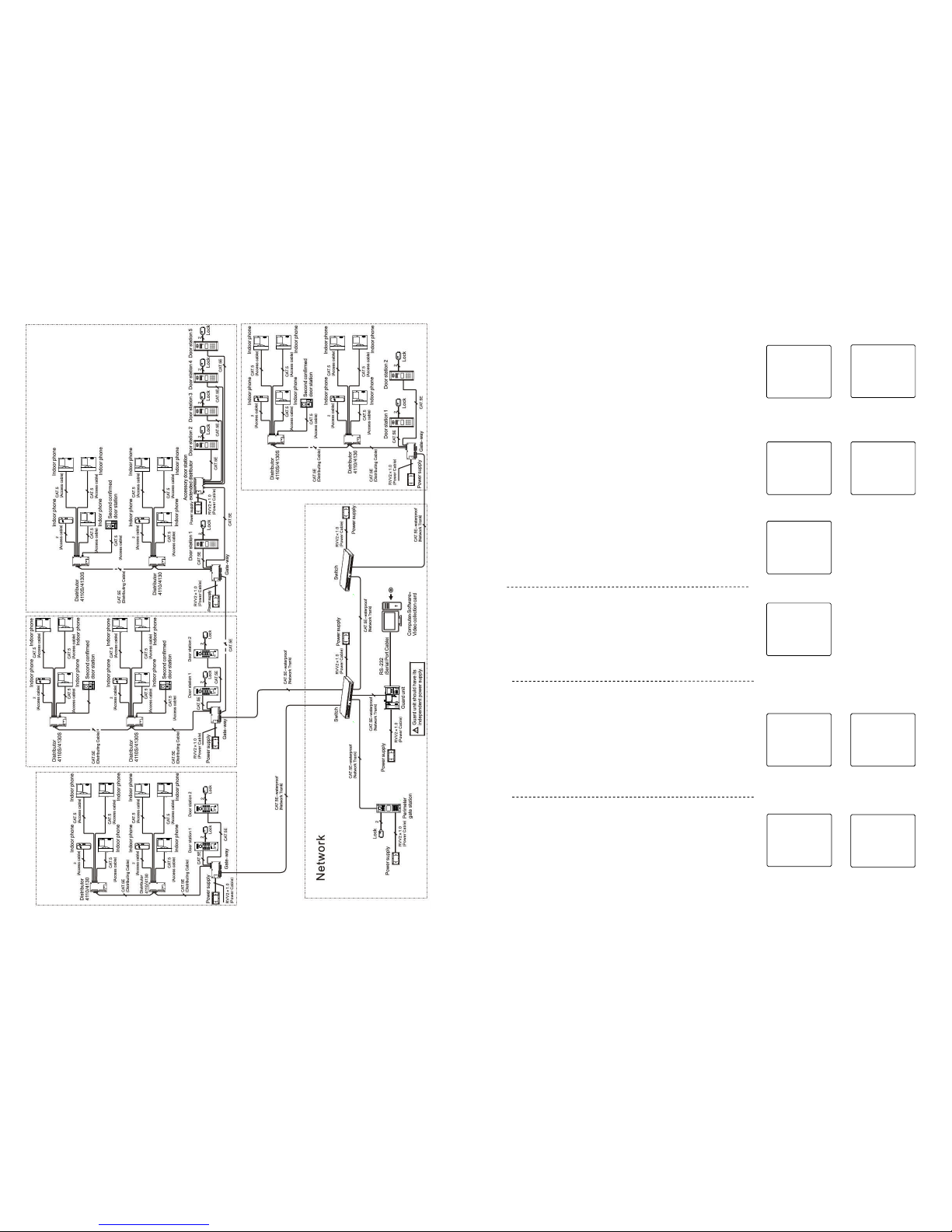
2. System wiring diagram
Page 8
5 50
3.Delete single card
In P7, choose “Delete Single”, press [#], LCD shows P11, enter
card No. according to hint, press [#] to confirm, or put card on
sensor of perimeter gate station, after successful deletion, shows
P12. Then you can proceed with the deletion of another card No.
by entering another card’s No. or putting card on sensor, press[*]
to back to P7.
Delete Single
No.:
Press # confirm
(11)
Delete Single
No. :0007234177
Card Deleted
(12)
4. Delete all cards
In P7, press [F2] to flip and choose “Delete All”, press [#] to
confirm, LCD shows P13.
Press [#] to confirm deletion, LCD shows P14, press [*] to back to
P7.
[Note] Be cautioustouse this function.
Delete All
Press * return
Press # confirm
(13)
5. Resident card check
In P7, press [F2] to flip and choose “Card Information”, press [#]
to confirm, LCD shows P15,screen shows all information about
registered cards. Press [*] to back to P7 after checking.
(15)
Delete All
Successful
(14)
Card Info.
No.: 0007234177
Seq. No.: 001
Qty.:012
■
Time setting
In P3, choose “Time & Date”, press [#], LCD shows P16, set time
according to hint, press [#] to confirm. Thes ystemwill back to P3
automatically after setting.
[Note] When setting, press [F3] and [F4] to movecursorto choose
function.
07-01-01
00:00:00
Monday
(16)
■
Password unlocking
In P3, choose “PW Unlock”, press [#], LCD shows P17, set the
unlock type, after setting, press [*] to back to P3.
0#: Public code (forbidden), user’s code (forbidden).
1#: Public code (allow), user’s code (forbidden).
2#: Public code (forbidden), user’s code (allow).
3#: Public code (allow), user’s code (allow).
Example: Enter [2], press [#] to confirm, LCD shows P18.
Unlock ByPW
Public PW (N)
Private PW (N)
0~3+# to choose
(17)
Unlock By PW
Public PW (Y)
Private PW (N)
0~3# to choose
(18)
■ Unlocking time
In P3, choose “Unlock Time”, press [#]to confirm, LCD shows
P19, enter unlocking time according to hint, press[#]to confirm.
After setting, press [*] to back to P3.
[Note] The unlock time length is from 1 second to 9 seconds. The
original is 1second.
For example: Enter[3], press[#]to confirm, LCD shows P20.
Unlock Time
5 Sec. Current
(19)
Unlock Time
3 Sec. Current
(20)
Page 9
49
Enter System
Change PW
Help
Under standby mode, press [F1], enter function main menu,
shows as P1.
SystemP assword:
_ _ _ _
In P1, choose “Enter System”, press[#] to confirm, LCDs howsP2,
enter system password 2-0-0-3.
[Note] This passwordissysteminitialcode,user can according to
their needs. Please refertoP42 for details.
System setting
If password is correct, it will enter P3, set system accordingly.
[Note] Usedirectionkey [F1] or [F2] to choose or flip, orpress[*] to
back to P1
.
Perimeter Gate
Alarm Setting
Card
Time & Date
(1)
(2)
(3)
■
Perimeter gate station No. setting
In P3, choose “Perimeter Gate”, press [#] to confirm, LCD shows
P4, enter perimeter gate station No. and switch port No.
[Note] Validscope for perimeter gate station No. isfrom01~09
;
Switch port No. is the port No. which perimeter gate station
connects withswitch.
Perimeter Gate:
01
Switch Port:
1
(4)
For example: Enter data according to h int, press [#] to confirm,
after successful registration, shows P5.
When finish setting, press [*] button to return to P3.
Perimeter Gate:
01
Switch Port:
3
(5)
In P7, choose “Register Single”, LCD shows P8, enter card No.
according to hint, press [#] to confirm, or put card on sensor of
perimeter gate station to finish single card registration.
After successful registration, P9 shows, enter next card’s No. or
put next card on sensor to begin new registration, or p ress [*] to
back to P7.
[Note] The ID card data is 10 digits ID card. When the ID card
number do notreach10, then please add “0”at front.
Register Single
No. :0007234177
Successful.
(9)
1.Register single card
In P3, choose “Card”, LCD shows P7, proceed settings for IC/ID
card here.
[Note] Use direction key [F1] or [F2] to choose function or flip, or
press [*]toback to P3.
RegisterSingle
Register Multi
RegisterPatrol
Delete Single
(7)
Register Single
No.:
Press # confirm
(8)
■
Card setting
Alarm Setting
1+# Choose ON
0+# Choose OFF
Current OFF
(6)
■Alarm setting
In P3 select “Alarm Setting”, press[#]to confirm, enter P6,
according the prompt to set the alarm ON/OFF.
[Note] Use direction key [F1]or[F2] to choose function, press[*]to
back to P3.
In P7, choose “Register Patrol”, press [#], LCD shows P10, enter
card No. according to hint, press [#] to confirm, after successful
registration, press[*] to back to P7.
Register Patrol
No.:
Press # confirm
(10)
2.Register patrol card
6
3. Product wiring diagram
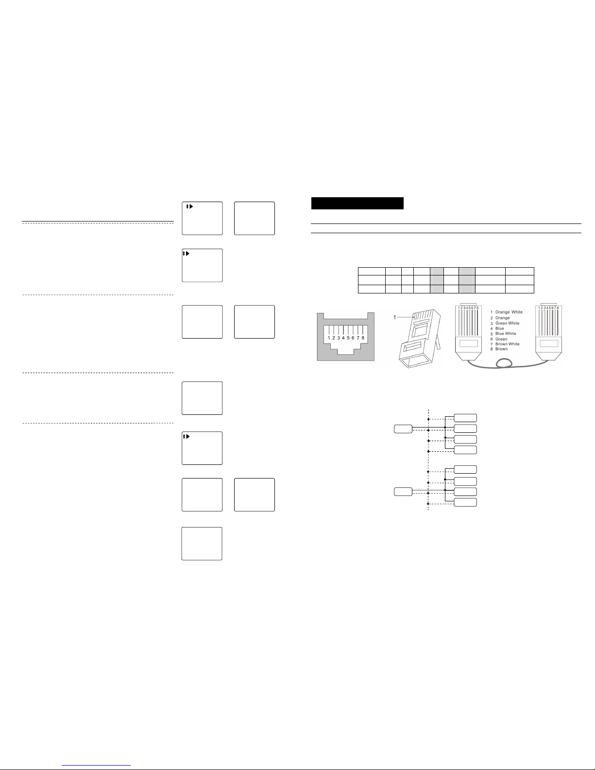
This section will introduce wiring diagram for every parts’ port in detail.
Connection explanation
1. C-5 cable connection explanation
All C-5 system use RJ45 connector, cable is in accordance with the international T568B standard, the order of wire from left to right is
orange white/ orange / green white/ blue/ blue white/ green/ brown white/ brown.
[Note] Pleasereferto Appendix4 for the plug-45makingmethod.
Pin No. 1 2 3 4 5 6 7 8
color ORW OR GRW BL BLW GR BRW BR
silk-screen LA LB VF- AF+ AF- VF+ GND/COM1 DC+/CO M2
2. UPS power supply connectionexplanation
When there are a lot of distributors used in the system and the sole gate way power supply can not load any more, some more power
supplies should be added to main line in the distributors.
[Notes] 1. When using one powersupplyformultiple distributors, the power supply is required to be connected to the middledistributor, the
position of powersupplyshould be symmetry.
2. When the main line in the same building using multiple power supplies, the DC+ line should be disconnected between any two
adjacent power supplies,butGND line should be linked together.
3. When one power supply supports the building that ismore than 6 floors, one RVV2X1.0 cable should be connected from DC+ and
GND of power supplytotheDC+ and GND of eachdistributor. This is to avoid the linelossthrough the long distance transmission.
Distributor 8
Power
Power
DC+
GND
GND
DC+
GND
Distributor 7
Distributor 6
Distributor 5
Distributor 4
Distributor 3
Distributor 2
Distributor 1
Page 10
7
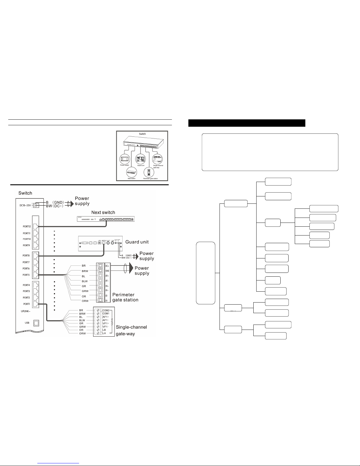
Switch wiring diagram
1. One port of switch can connect:1 perimeter gate station/ 1 guard unit/
1
network spur track(which can connect at most for 63 gate-ways,
adopts
hand in hand connection method)/ 1 switch
48
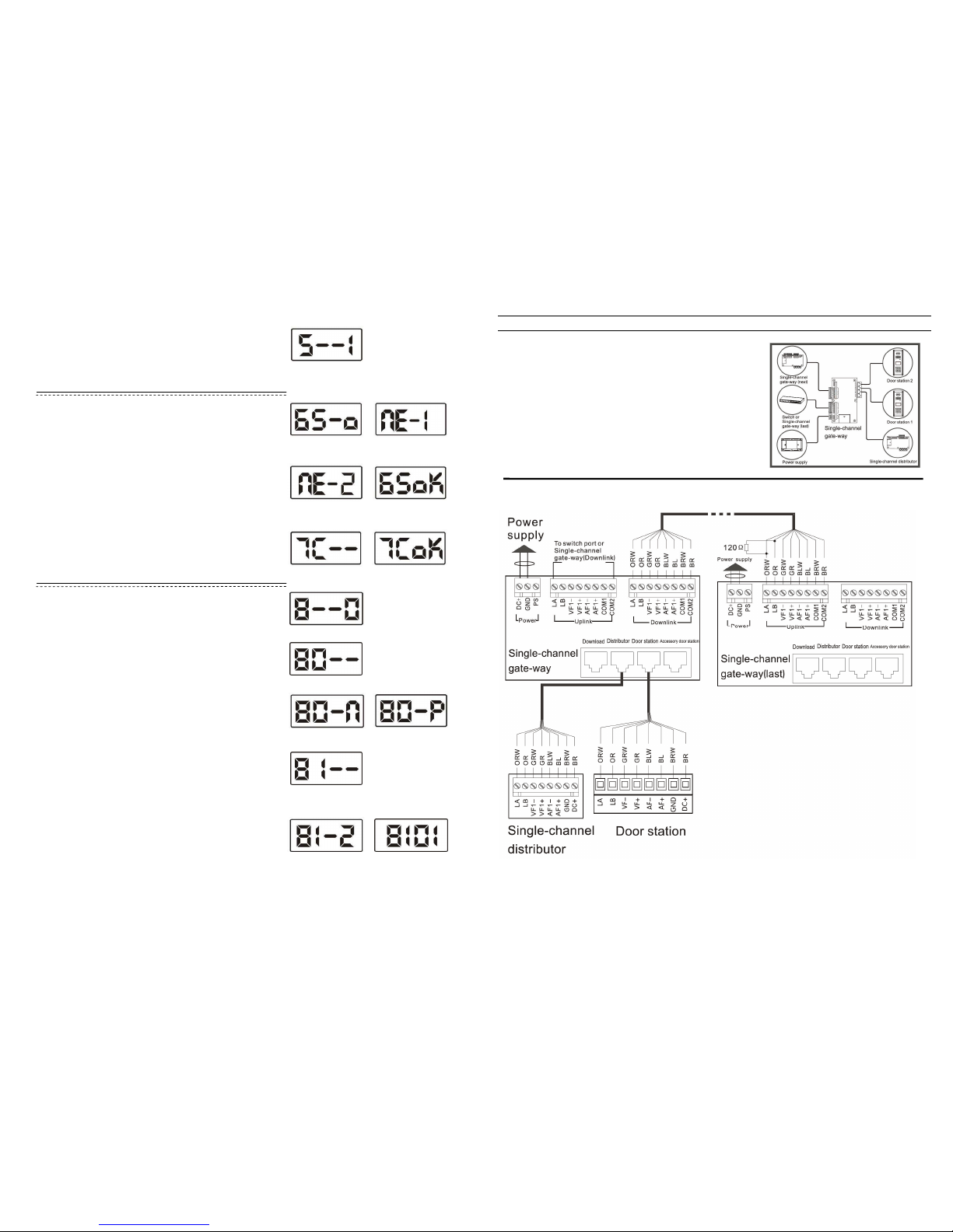
Appendix 3. Perimeter gate station operation explanation
Enter System
Perimeter Gate
Card
Register Single
Register Patrol
Delete Single
Delete All
Time & Date
PW Unlock
Unlock Time
System PW
Public PW
Operate Guide
Version No.
Change
Help
Menu
Bit
Card Info
Key Function:
[F1]:To enter function menu and direction key(up). [1~9]:
To enter figures or
characters
[F2]:Direction key(down ) [#]:Confirm key
[F3]: Direction key(left),public password unlocking [*]:Quit
[F4]: Direction key(right) ,resident password unlocking
Alarm Setting
Language
Page 11
47
■
Unlocking time
In the menu of P3, input [4] +[#]. The LCD will show as P24. The
right number shows current unlock time. It will c hange after input
a new number, then press [#] button to confirm.
[Note] Unlocktimeis from 1s to 9S.
(24)
Change password
■
Change system password
In the menu of P3, input [6] + [#]. The LCD will show as P25.
Input the password, if it is correct, LCD will show as P26.
Input the new password, LCD will show as P27, then repeat to
input the password again, press [#] button to confirm. After finish,
the LCD will show as P28.
[Note] The systemoriginalpassword is 2003.
(25)
(27)
(26)
(28)
■
Chang
e public password
In the menu of P3, input [7] + [#]. The LCD will s how as P29.
Input the new password, press button to confirm. After finish, the
LCD will show as P30.
[Note] The originalpublicpassword is 1234.
(29)
(30)
(31)
(33)
(34)
(32)
(35)
(36) (37)
Lift Setting
■
Lift
In the menu of P31, input [0] + [#]. The LCD will show as P32.
Input [0]+[#], lift control function is OFF. The LCD will show as P33.
Input [1]+[#], lift control function is OFF. The LCD will show as P34.
After finish, press [*] button return to P31.
■
Floor Setting
In the menu of P31, input [1]+[#]. The LCD will show as P35.
Input the floor number, press [ # ] button to confirm.
e.g. Second underground floor, input F3+[2], as the P36 shows.
1 floor, input [0]+[1] ,as the P37 shows.
In the menu of P3, input [8] + [#]. The LCD will show as P31.
■ Change resident password
In the standby state, press [F2] button, the LCD will show as P38.
Input the digit as follows prompt:
◆Room number e.g.0101
◆Current password e,g.1234
◆New password e,g.5678
◆Repeat the new password e.g.5678
If the password is correct, the door station willso unda long beep,
then return to standby state.
8
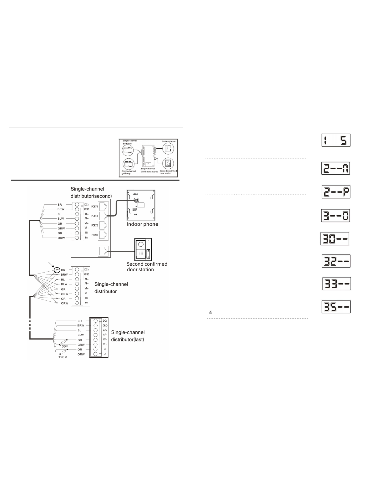
Gate-way wiring diagram
1. Acc essorydoo rstation’s wiring method is the same as door station.
2. Between the [Uplink] terminals (LA, LB) on the last gate way in the n
etwork
should have 120Ω resistance, [Downlink] terminals
do not need to be
connected.
3. When wiring for power supply, PS ports should not be connected.
Page 12
9
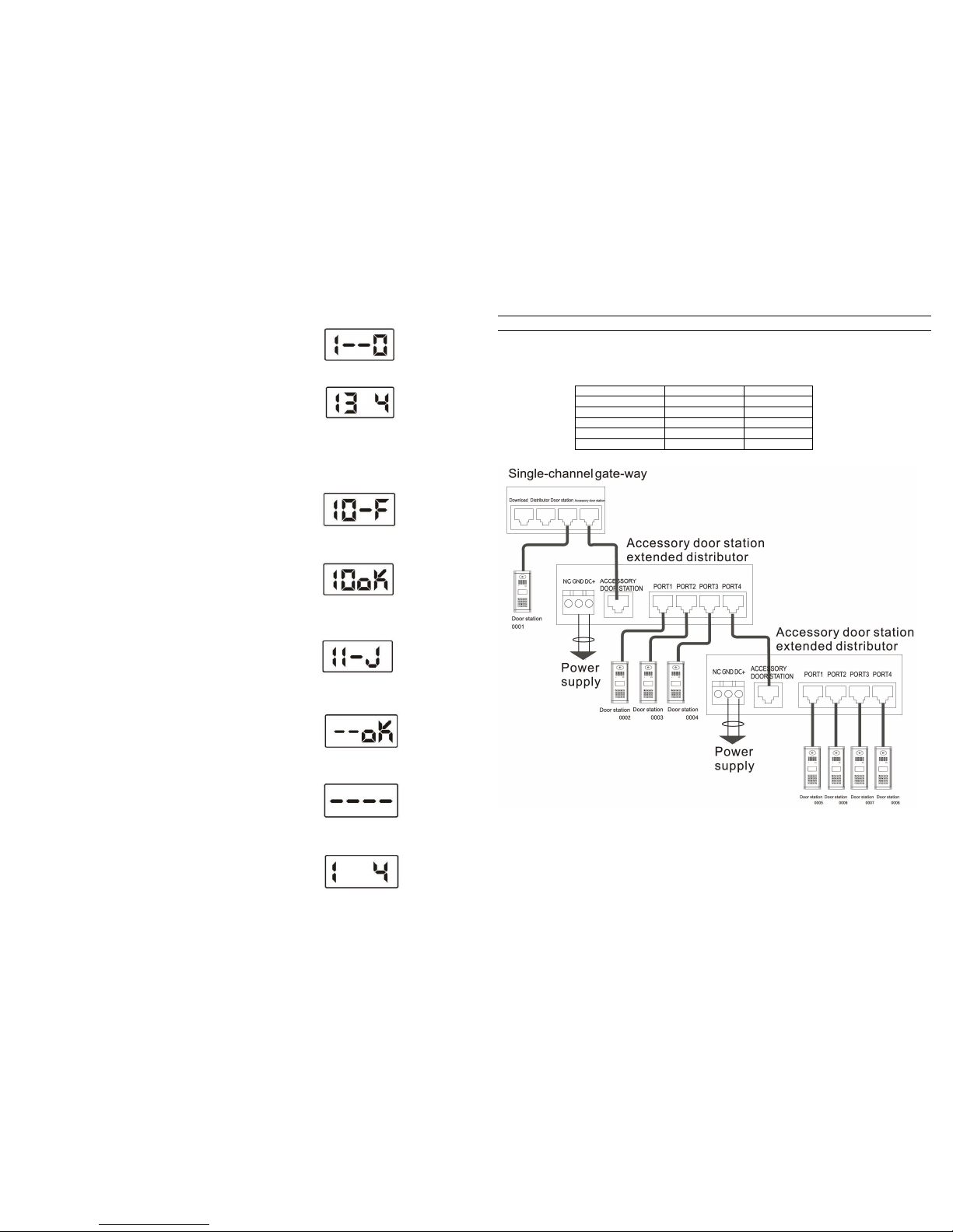
Distributor wiring diagram
1. PORT1~PORT4 is used for indoor phone connection
2. Second confirmed door station should be connected with the apartment
distributor that is specified for second confirmed door station.
3. All the same signal line of up-link and down-link should be twisted together
first before connecting to the distributor.
4. Between LA and LB on the last distributor in the unit should have 120Ω
resistor,between VF+、VF-should have a 100Ω resistor.
Twist
46
V
. Indoor phone data
down
load
In the menu of P8, input [5]+ [#]. The LCD will show as P16. After
finish, press [*] to back to P3
[Note] This function is for download the indoor phone information
saved in gate-way to door stationwhenin network.
Alarm Setting
In the menu of P3, input [2]+[#]. The LCD will show as P17.
Input [0]+ [#],door alarm is OFF, as P17 shows.
Input [1]+[#], door alarm is ON, as P18 shows.
After finish, press [*] to back to P3
(16)
(17)
(18)
■ Card registering
In the menu of P3, input [3]+[#]. The LCD will show as P19.
Here proceed IC/ID card setting
1. Resister single card
In the menu of P19, input [0]+[#],The LCD will show as P20.
input card No.,press[#] to confirm,or put card on door station’s
card reader,and finish single card registration
(19)
(20)
(21)
(22)
(23)
3.Delete single card
In the menu of P19, input [3]+[#],The LCD will show as P22.
Input card No.,press[#] to confirm,or put card ondoo rstation’s
card reader,and finish single card deletion.
2.Register patrol card
In the menu of P19, input [2]+[#],The LCD will show as P21.
input card No.,press[#]to confirm ,orput card on door station’s
card reader,and finish patrol card registration
4. Delete all cards
In th e menu of P19, input [5]+[#],The LCD will show as P23.
Press [#] to confirm delete. After finish, press[*] to back to P3
[ ] Be cautious tousethis operation.
■
Password Unlock Setting
In th e menu of P3, input [4]+[#], then begin to set the Public
PW and the Private PW ON/OFF.
[0]+[#]:Public PW(OFF) ,user’s PW(OFF)
[1]+[#]:Public PW(ON) ,user’s PW(OFF) ;
[2]+[#]:Public PW(OFF) ,user’s PW(ON)
[3]+[#]:Public PW(ON) ,user’s PW(ON)
Page 13
45
I.Indoor phone digit
In the menu of P8, input [3] + [#] , the LCD will shows as P9.
The right number sho ws the current indoo r phone digit. Input the
new number (2~4), and press [ # ] button to confirm.
[Note] You should choose the indoor phone digit first, then you
can proceed withthe indoor phonenumbersetting.
1.
Indoor phone setting
In the menu of P3, input [1]+[#],, the LCD will shows a s P8, the
information of indoor phone can be set here.
(8)
(9)
Then proceed with indo or phone information input,there are two input m odes:Single input mode
and matrix input mode,us er can choose what they need.
II. Single input mode
In the menu of P8, input [0]+[#], the LCD will show as P10.
Input the indoor phone No., distributor No., port No., and ring No.
in turn.
◆ Indoor phone No: 2~4 digit No.(Digit is depended on the last
indoor phone digit) e.g. 0101
◆ Distributor No:Input the distributor No. ofindoor phone, valid
scope:001~254 e.g.001
◆ Port No.:Input distributor port No.c onnectingto indoor phone
valid scope:1~4 e.g. 1
◆ Ring:This system offers 3 types of ring for user t o choose,
input ring No.(1~3) e.g. 3
After finish, the LCD shows as P11, input next indoor phone No.
or press [*] to back to P8.
[Note] 1. Ringingis only heard when indoor phoneiscalled.
2. When system’s ring is chord, there are 3 types of rings for
chosen, otherwise itisalways “Dingdong”ring when choose1 -3.
(10)
(11)
(12)
(13)
(15)
(14)
In the menu of P8, input [1]+[#], the LCD will show as P12.
◆ Start No: Input the start indoor phone No. e.g. 0101
◆ End No: Input the last indoor phone No. e.g. 0704
◆ Ring Type: Input ring number (1~3) e.g.1
◆ Password:Input resident password e.g. 1234
After finish, the LCD shows as P13, press [*] to back to P8.
[Note] The original password is 1-2-3-4. You can refer to “Appendix 2”
→
”Changepassword”to change it.
III. matrix input mode
[Note] This mode is only suitable for buildings with matrix
structure,if every floor has different quantity of apartment,
then s
hould choose singleinput mode.
IV. Indoor phone data upload
In the menu of P8, input [4]+[#]. The LCD will show as P14,
finally the LCD shows the upload result which is P15
Press [*] back to P8.
[Note] This function is for upload indoor phone data saved in door
station to gate-way when innetwork.
10
Door station extender diagram
1. Door station should be set for busy mode: Switch offpo wer, press the button 1 on door station then switch on power.After this, when
one door station is used, other door station will show “system busy”, this can prevent system conflicts.
2. When setting ports for door station and gate-way, the ports No. should be set as the following sequence.
Door station No. Gate way port No.
door station 0001 1
accessory door station 1 0002 2
accessory door station 2 0003 3
… … …
accessory door station7 0008 8
Page 14
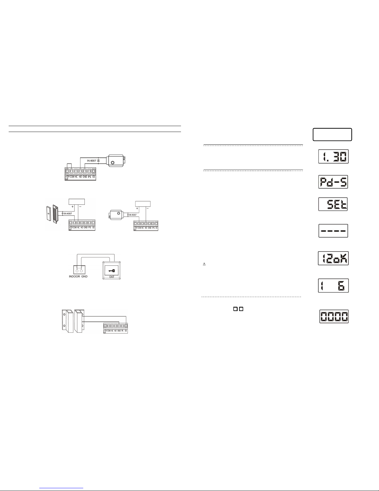
11
Door station lock diagram
System provides two ways of electric lock connection for user to choose: Power unlock and signal unlock. (Note: For oversea m arket,
always use the signal unlock).
1. Power unlock
2. Signal unlock
Normal open type lock wiring Normal closed type lock wiring
[Note] Thiswayof unlocking needs DC12V separate power supply.
3. Exit button unlocking
4. Door alarm diagram
Connect the door station [GS] terminal to the door alert sensor as follows show, the door station will send alarm message to managing
center if the door is opened for more than 120s.
[Note] There aretwomethods to switch this functionOFF.
1. Connect the[GS]terminal to earth.
2. Refer to the“Appendix1~2. door station operation explanation”→ “Alarm Setting” to set it OFF.
Short circuit
Power supply
Power supply
Door station terminal
Door station terminal Door station terminal
Electric lock
Electric lock
Magnetic lock
44
Press [F1] button, enter the menu
The LCD displays as P2. Input the system password.
[Note] The system original password is 2003. Please refer to
“SystemPW”tochange it.
System Setting
If the password is correct, it will enter P3 automatically, here can
proceed system functions setting.
[ # ] :Confirm
[ * ]:Quit
Restore Default Password
Hold [*] button on t he door station, then connect the power, the
default password will be restored. And the LCD will show the
version number of software.
[Note] The P1isfor example.
This door station has series of functions, and each function has
(1)
(2)
(3)
(7)
(4)
(5)
(6)
■ Door station setting
In the menu of P3, input
0
#
, enter the door station number
setting, it will show as P7 for the first time setting.
Input door station number, e.g.:0101
Input the gate-way port which connect to the door station, e.g.: 1
Press [#] button to confirm, it will automatically return to P2.
[Note] Door station’s No. is from 0001, Port No. of gate-way please
refer to theportof gate-way connected to door station.
2. Cancel gate-way data
1. Cancel all indoor phoneNo.
In P3, input [1]+[#] , then input [2]+[#] to clean all the indoor
phone information. The LCD will shows as P4 during process.
If c learance successful, a long sound of “di” can be heard and
LCD shows as P5, press [*] button to back to menu of P3.
[ ] This function isusedin the first time setting only.
Data clearance
For first time setting, system data clearance is needed
In the menu of P3, input [6]+[#] to clear the information in the
gate-way. After clearance, a long sound of “di” can be heard and
the LCD shows as P6, press [*] button to back to menu of P3.
Page 15
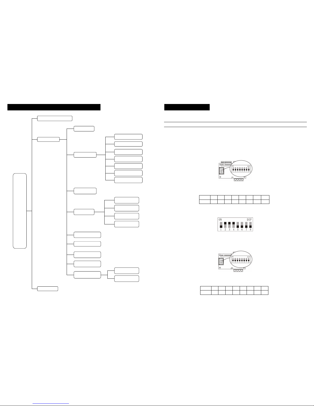
43
Appendix 2. LED door station operation explanation
Enter System [F1]
Door station [0+#]
Indoor phone [1+#]
Single Input [0+#]
Matrix Input [1+#]
Clear Data [2+#]
Bit [3+#]
Alarm Setting [2+#]
Card [3+#]
Register Single [0+#]
Register Patrol [2+#]
Delete Single [3+#]
Delete All [5+#]
PW unlock [4+#]
Unlock Time [5+#]
System PW [6+#]
Public PW [7+#]
Menu
Upload [4+#]
Download [5+#]
Clear Gate-way [6+#]
Restore Default Password [*]
Private PW [F2]
Lift Setting [8+#]
Lift [0+#]
Floor Setting [1+#]
12
4. System programming
According to product wiring diagram, connect all the parts and then start system programming. Programming should follow the
sequence from a building to network system. Programming products in a building first, then program system products in network.
Building programming
First step: Hardware setting
This step is to set address for gate-way and distributor.
[Note] 1.All the gate-way number which connect to thesame port of switch should notbe repeat.
2. Allthedistributor number which connect to thesame gate-wayshouldnot be repeat.
3. Please takerecordof the gate-way number and distributornumber, these information maybeused in the coming setting.
■ Address gate-way (Set gate-waynumber)
1. DIP switch (it is in the cover plate on the left side of gate-way), show as below:
2. Address range :001~063
3. Address calculating: According to the form below, plus all the number that is on the [ON] position, and you will get the address
number.
DIP 1 2 3 4 5 6 7 8
Digits 1 2 4 8 16 32 none none
[Note] Whensettingaddress, please according tosequenceof unit order to setnumbers/digits(DIP 7-8 is invalid, and can notbe set on
[ON] position to theDIP7and DIP8.)
e.g.:
From the above picture, the digit is =2+4+8=14, so the gate-way’s address/number is 014.
■ Address distributor (Set distributor number)
1. DIP switch (it is in the cover plate on the left side of distributor), show as below pictures
2. Address range :001~254
3. Address calculating: According to below form, add all digits on [ON] position to get the address number.
DIP 1 2 3 4 5 6 7 8
Digit 1 2 4 8 16 32 64 128
Page 16
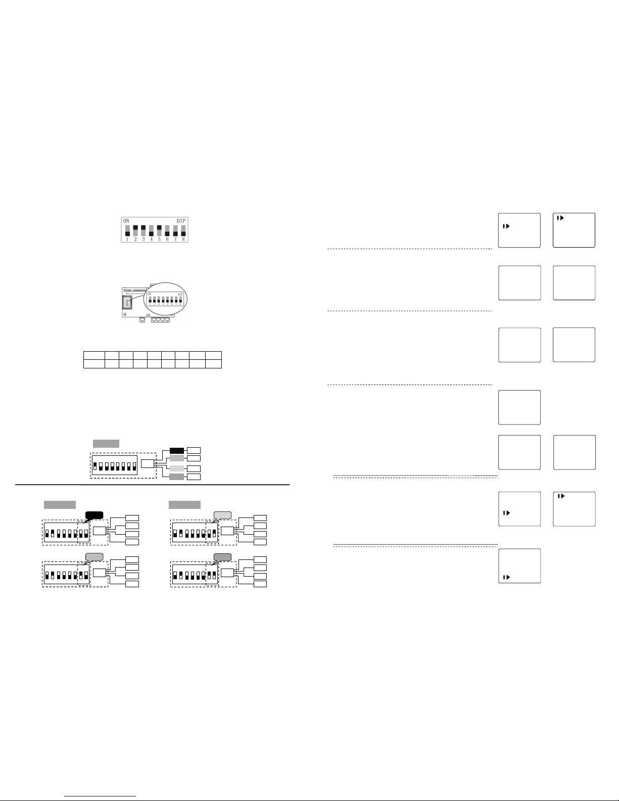
13
e.g.:
From the above form: the digit is=2+4+16=22, so the distributer’s address/number is 022.
■ Apartment distributer programming
1. DIP switch (it is in cover plate on the left side of distributor)
2. Address range: 001~063.
3. Address calculating: According to the form below, add all the digits on the [ON] position to get the address number.
DIP 1 2 3 4 5 6 7 8
Digit 1 2 4 8 16 32 none none
When each apartment needs only 1 indoor phone, then the distributor can use 4110 or 4130, and 4 ports of distributors connect to 4
different indoor phones in different apartments.
If one apartment wants to have 2 or more indoor phones, then distributor 4110S or 4130S should be used, and 4 ports of the distributor
connect to the indoor phones in the same apartment.
During the programming, the address number of the any two 4110/4130 distributors should be different with each other, while the
address number of 4 distributor 4110S/4130S can be the same by setting the DIP 1-6 the same digit, while DIP7 and 8 different. Details
refer to the below illustration.
4110/ 4130
001
ON
DIP
1234567
8
101
102
103
104
PORT1
PORT2
PORT4
Distributor
4110S/ 4130S
Indoor phone
002
ON
DIP
1234567
8
2
01
201
201
201
PORT3
PORT 1
002
ON
DIP
1 2 3 4 5 6 7 8
202
202
202
202
PORT 2
002
ON
DIP
1234567
8
203
203
203
203
PORT 3
002
1234567
8
204
204
204
204
PORT 4
Distributor
4110S/ 4130S
Indoor phone
Distributor
Indoor phone
42
Enter System
Change PW
Help
Status
Press [*] to back to P1, select “Change PW”, as P42 shows.
Press [#] to confirm,enter P43.
■ Change system password
In P43, choose “System PW”, LCD shows P44, change system
password according to hint.
e.g.: After input password, press [#], if password is correct,
LCD shows P45, press [*] to back to P43.
[Note] For the first timechange,the initial password is 2003.
Current : _ __ _
New: _ _ _ _
Confirm: _ _ _ _
Press # Confirm
System PW
Private PW
Public PW
■ Change resident password
In P43, choose “Private PW” , press [#], LCD shows P46, ente r
room No. and password according to hint.
[Note] For the first timechange,the initial password is 1234.
Change PW
Indoorphone:_ _ _ _
Password:_ _ _ _
Current : ****
New: ****
Confirm: ****
Successful
(42)
(43)
(44)
Current : ****
New : * ***
Confirm :** * *
Successful
If the password is correct, then enter new password setting.
Enter the new password twice, and press[#] to confirm, if change
is successful, then shows P47. LCD will back to standby mode
automatically.
(45)
(46) (47)
Change password
System Password :
_ _ _ _
Enter System
Change PW
Help
Status
Operate Guide
Version No.
Enter System
Change PW
Help
Status
Current : _ __ _
New: __ __
Confirm :_ __ _
Press # confirm
(48)
(49)
Current : ** * *
New :*** *
Confirm : * ***
Successful
(50)
(51)
(52)
(53)
In P43, choose “Public PW”, press [#] to confirm, LCD shows
P48, enter system password, then change the public password.
Press [*] to back to P1 ,which is the main menu of function,
choose “Help”, as P51 shows.
User’s guide
Press [#], LCD shows P52, here press F1 or F2 to check the
operation explanation and version No., press [*] to back to P51.
In P1, choose “Status”, LCD shows P53, press [#] to look up all
user’s information which saved in system.
Status check
If the system code entered is correct, LCD shows P49, according
to the hints, change the public password, after change, screen
shows P50, press [*] to back to P43.
[Note] Forthefirst time change, the initial passwordis 1234 .
■
Change public password
Page 17
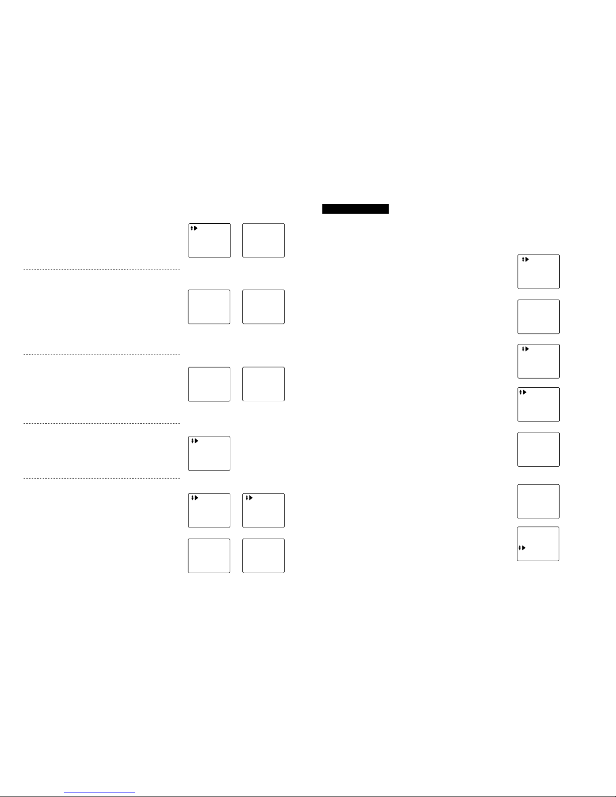
41
■
Time adjustment
In P3, press [F1] or [F2] to select “Time & Date”, as P31 shows.
Press [#] to c onfirm, LCD shows P32, set time acco rding to hint,
press [#] to confirm. After finish adjus tment, the system will be
back to P31 automatically.
[Note] When setting, can use [F3]and [F4] to move cursor left and
right for selecting
。
Time & Date
PW Unlock
Unlock Time
Language
(31)
07-01-01
00:00:00
Monday
(32)
■Password unlocking
In P31, press [F2] to select “PW Unlock” , press [#], LCD shows
P33, set the right password unlocking type to unlock the door.
Press [*] to back to P31 when finish.
0#: Public PW (forbidden), user’s PW (forbidden).
1#: Public PW (allow), user’s PW (forbidden).
2#: Public PW (forbidden), user’s PW (allow).
3#: Public PW (allow), user’s PW (allow).
e.g.: Press 2, then press #, the LCD will show P34.
Unlock By PW
Public PW (N)
Private PW (N)
0~3+# to choose
(33)
Unlock ByPW
Public PW (N)
Private PW (Y)
0~3+# to choose
(34)
■ Unlocking time
In P31, press [F2] to select “Unlock Time”, press [#] to confirm,
LCD shows P35, set unlocking time according to hint, press [#] to
confirm. Press [*] to back to P31 when finish.
[Note] The unlocking time lengthis from 1 second to 9 seconds. For
the ex-factory, the initialis 1 second.
e.g.:Input [3], press[#]to confirm, LCD will show P36.
Unlock Time
5 Sec. Current
(35)
Unlock Time
3 Sec. Current
(36)
■ Language
In P31, press [F2] to select “Language”, press [#] to confirm, LCD
shows P37, set language according to hint, press [#] to confirm.
简体中文
English
(37)
■ Lift setting
In P3, press [F1] or [F2] to select “Lift setting”, as P38 shows.
Press [#] to confirm, LCD shows P39.
1. Lift
In P39, press [F1] or [F2]to select “Lift”, press[#] to confirm, LCD
shows P40. Set lift ON/ OFF according to hint.
2. Floor Setting
In P39, press [F1] or [F2] to select “Floor Setting”, press [#] to
confirm. LCD shows P41.Inp utthe start floor number, press [#] to
confirm.
Lift Setting
(38)
Lift
Floor Setting
(39)
Lift
1+# Choose ON
0+# Choose OFF
Current OFF
(40)
Floor Setting
0 6
(41)
14
(LCD door station)
Step 2: Door station programming
1. Memory/Information clearance (Only used in the first time programming)
Enter System
Change PW
Help
Status
On standby mode, press[F1] key, enter function main menu as
P1 shows,select “EnterSystem” , and press [#]key to confirm.
SystemP assword:
――――
LCD shows as P2,input system password: 2-0-0-3
[Note] This passwordis the original one
If the system password is correct, automatically enter P3,press
F2 to select indoor phone ,press # key to confirm
Door Station
Indoor Phone
Distributor
Card
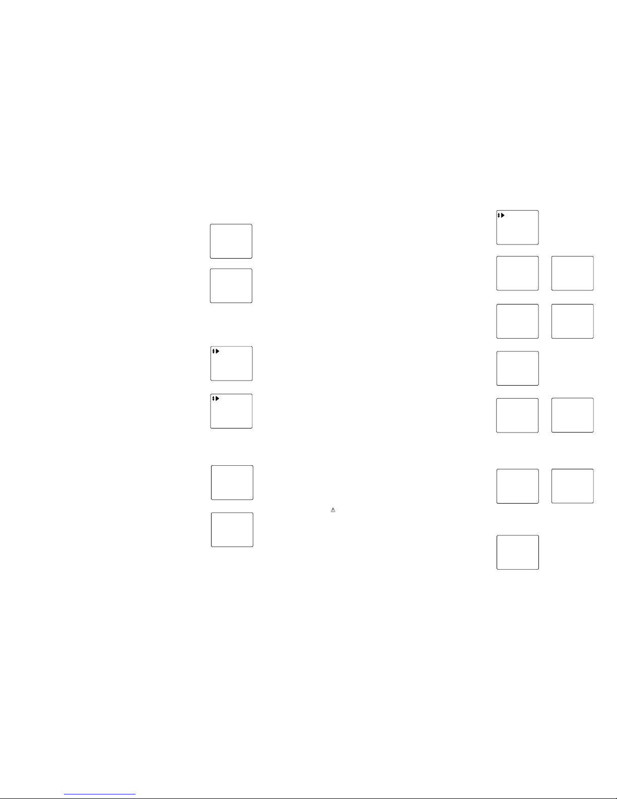
(1)
(2)
(3)
Enter P4 , press F2 to select “Clear Data” and press [#] to
confirm
Single Input
Matrix Input
Clear Data
Bit
(4)
LCD shows as P5, press [#] key
Clear Data
Press *return
Press # confirm
(5)
If c learance successful, a long sound of “di” can be heard and
LCD shows as P6, press [*] key to back to menu of P4
In the menu of P4, press F1 or F2 to flip, choose “Clear
Gate-Way” and press [#] to confirm. After clearance LCD shows
as P7, press [*] to back to menu of P3
Clear Data
Successful.
(6)
Upload
Download
Clear Gate-Way
Successful
(7)
Page 18
15
2. Door StationNo. setting
3. Indoor phone setting
I.Indoor phone digit
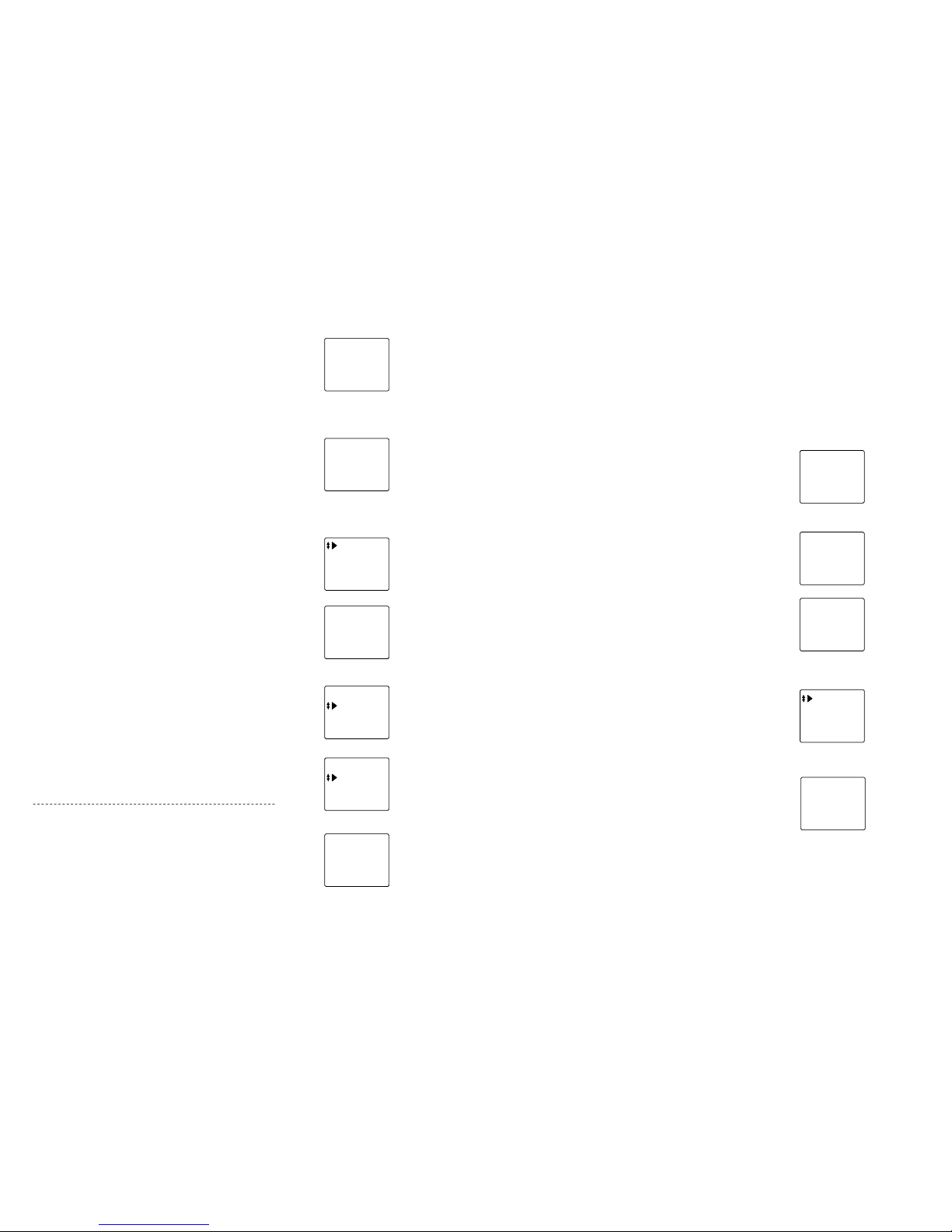
In P10, choose d igit of indoor phone No.,press[#] to confirm,
LCD shows as P11,according to residents’ room No. digit. Press
[F1]or[F2]to select indoor phone digit,and press [#] to confirm,
after setting, back to P10 automatically.
[Note] Youshouldchoose the indoor phone digitfirst, then youcan
proceed with theindoorphone number setting.
2 bits
3 bits
4 bits
4 bits Current
(11)
II. Single input mode
Indoor phone:_ _ __
Distributor: _ _ _
Port No.: _
Ring Type: _
Then proceed with indoor phone information input,there are two input m odes:Single input m ode and
matrix input mode,user can choose what they need.
(12)
Indoorphone:0101
Distributor:001
Port No.:3
Ring Type:3
(13)
Choose indoor phone in P3, press[#]button to confirm,and enter
P10,the information of indoor phone can be set here.
[Note] By direction key [F1] or [F2]to choose function or flip,press
[*] key tobackto P3.
(10)
Single Input
Matrix Input
Clear Data
Bit
In P10, choose single input mode,press[#]to confirm , LCD
shows as P12.
◆ Indoor phone No.:2~4digit No.(Digit is depended on the last
indoor phone digit)
◆ Distributor No:Input the distributor No. of indoor phone, valid
scope:001~254
◆Port No.:Input distributor port No. connecting to indoor phone
valid scope:1~4
◆ Ring:This system offers 3 types of ring for user to choose,
input ring No.(1~3)
Input data according to the indication, as P13 shows.
Select “door station” in the menu of P3, press [#] to confirm, then
LCD shows as P8, input door station No. and gate-way port here.
[Note] Door station’s No. is from 0001, Port No. of gate-way please
refer to theportof gate-way connected to door station
Door station No.
0001
Gate-Way Port :
1
(8
)
e.g.: The No. of the 6th door station in the building is 0006.
gateway port is 6,after successfully setting, a long sound
of “di” can be heard,and the LCD shows as P9
Press * button to return to P3 after finish.
Door station No.
0006
Gate-Way Port :
6
(9
)
40
In P21, choose “Register Single”, LCD shows P23, according to
hint, input card No., press [#] to confirm, or put card on door
station’s sensor, and finish single card registration.
After successful registration, shows P24, then input another
card’s No. or put that card on sensorto begin new registration, or
press [*]to return to P22.
[Note]The card digits shouldbe10 digits. If the card number do not
reach 10 digits, then you need to add the 0 in front to make it
to be 10digits.
Register Single
No. :0007234177
Successful.
(24)
1. Resister single card
In P3, ch oose “Card”, LCD shows P22, here proceed IC/ID card
setting.
[Note]Use direction key [F1]or[F2] to choose or flip menu, or press
[*] to back toP3 .
RegisterSingle
Register Multi
RegisterPatrol
Delete Single
(22)
Register Single
No.:
Press # confirm
(23)
■Card registering
In P22, choose “Register Patrol”, press [#], input card No.
according to hint, press [#] to confirm, after successful
registration LCD shows P25, press [*] to return to P22.
(25)
3.Delete single card
In P22, choose “Delete Single”, press[#]and LCD shows P26,
input card No. according to hint or put card on sensor and press
[#] to confirm, after successful delete, screen shows P27.Use
this same way to delete next card No. by entering the card
number or putting card on sensor for delection, press [#] to
confirm, press [*] to return to P22.
Delete Single
No.:
Press # confirm
(26)
Delete Single
No. :0007234177
Successful
(27)
2.Register patrol card
Register Patrol
No.: 1245422867
Successful
4.Delete all cards
In P22, press[F2] to select “Delete All”,press [#] to confirm,L CD
shows P28.
Press [#] to confirm delete, LCD s hows P29, press[*] to back to
P22.
[ ] Be cautioustouse this operation.
Delete All
Press * return
Press # confirm
(28)
Delete All
Successful
(29)
Register Single
No. :0007234177
Floor: 06
Successful.
(24)*
Register Single
No.:
Floor:
Press # confirm
(23)*
5.Check resident card
In P22, press[F2] to select “Card Information”, press[#]to confirm,
LCD shows P30, screen shows all information for registered
card, after inquiry, press [*]to back to P22.
Card Info.
No.: 0007234177
Seq. No.:001
Qty.:012
(30)
Page 19
39
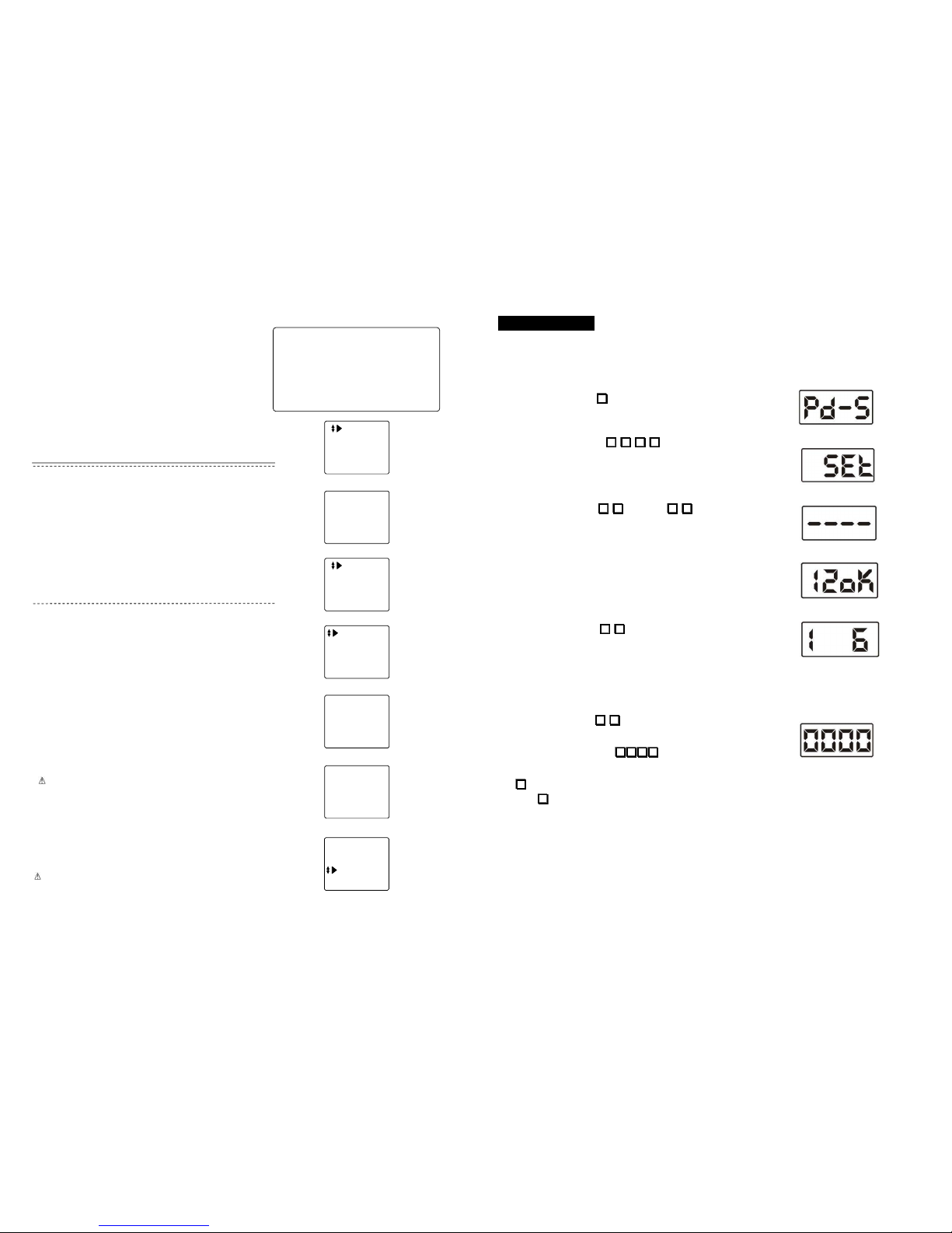
3.Matrix input mode
[Note] This mode is only suitable for building with structure of matrix,if the
structure is differentbetween floors, pleasechoosesingle input mode.
In P10, choose “Matrix Input”, press [#] to confirm, LCD show
P15, input data according to hint.
◆ Start No.: Input start No. of indoor phone.
◆ End No.: Input last No. of indoor phone.
◆ Ring Type: Setting is the same as “Single Input”.
◆ Password: Input resident password:1234.
[Note] Thiscode is initial code,users canreviseit in function form
,
please refer to“Change PW”part.
Press * button to back to P10.
Start No.:__ _ _
End No. :__ _ _
Ring Type:_
Password:_ _ __
(15)
Start No.:01 0 4
End No. :20 0 4
Ring Type:2
Password: ** * *
(16)
e.g.: A building has 20 floors, each floor has 4 apartments.The
indoor phone start No. is 0101, end No. is 2004.
Distributor No. is from 001to 020.
The ring for door station calling indoor phone: ring 2.
Resident password: 1-2-3-4.
Setting as P16 shows, after input password, if there is no error,
P17 will show and back to P15, at this time another data can be
input, also can press [*] to back to P10.
4. Indoor phone data upload
[Note] This function is for upload indoor phone data saved in door
station to gate-way when innetwork.
In P10, press [F1] or [F2] to flip menu, choose “Upload”, shows
as P17, press[#]to confirm, and start to upload data, finally
screen shows the upload result which is P18 .
Press [*]to back to P17.
5. Indoor phone data download
[Note] This function is for download the indoor phone information
saved ingate-wayto door station when in network.
In P17, choose “Download”, press[#]to confirm, LCD shows data
download status.
As P18 shows.
After data download completed, LCD shows P19, press[*]to back
to P16.
Upload
Download
Clear Data
Please wait…
Upload
Download
Clear Data
Successful
(19)
(20)
Seq. No.:080
Indoorphone.:2004
Distributor020-4
Ring Type:2
(18)
Upload
Download
Clear Gate-way
(17)
Alarm Setting
1+# Choose ON
0+# Choose OFF
Current OFF
(21)
■ Alarm setting
In P3 select “Alarm Setting”, press [#] to confirm, enter P21,
according the prompt to set the alarm ON/OFF.
[Note] Use direction key [F1] or [F2] to choose function, press [*]to
back to P3.
16
III. Matrix input mode
[Note] This mode isonlysuitable for buildings withmatrixstructure,if every floor hasdifferentquantity of apartment, then should
choose single inputmode.
In P10, choose matrix input mode,press[#]to confirm, LCD
shows as P15,input data according to hint
◆ Start No.:Input the starti ndoor phone No.
◆ End No:Input the last indoor phone No.
◆ Ring Type:3 types of ring for user to choose,input ring No.
(1~3)
◆ Password:Input resident password:1-2-3-4
A
fter
finish,
input press [*] to return to P10
Start No.: _ __ _
End No. : _ _ __
Ring Type:_
Password: _ _ __
(15)
Start No.: 01 0 1
End No. : 200 4
Ring Type:2
Password:* ** *
(16)
Successful
(17)
e.g.: A building has 20 floors, each floor has 4 apartments. The
indoor phone start No. is 0101,end No. is 2004.
Distributor No. is from 001to 020
The ring for door station calling indoor phone:ring 2
Resident password:1-2-3-4
Setting as P16 shows, after input password, if there is no error,
P17 will show and back to P15automatically ,thenyou can input
another data, also you can press [*] to back to P10.
After finish, back to P12,inputne xt indoor phone No. or press [*]
to back to P10.
[Note] 1. Ringingwill be heard when indoor phone iscalled
2. When system’s ring ischord melody type, there are3types
of rings for chosen. If the door station is with Dingdong ring
type, thenitis always “Dingdong”ring when choose1-3.
Upload
Download
Clear Data
(19)
Seq. No.:080
Indoorphone.:2004
Distributor001-1
Ring Type:2
(20)
IV
. Data upload
After indoor phone information set/program through door station,
all data is saved in door station, when connecting system to
network, these data need to be upload to gate-way
Page 20

17
Step 3. Testing basic functions
To test and check each device whether they work properly or not.
1. Door station calling indoor phone
Input room No. on door station to call indoor phone, indoor phone answers and unlocks the door.
Malfunction 1. Door station shows: Fail-2.
● Check the wiring between door station and gate-way, distributor and gate-way
● Check if the DIP digit set in distributor is the same with the indoor phone setting on door station.
Malfunction 2. Door station enters ringing status, indoor phone doesn’t response.
●Check wiring between indoor phone and distributor.
2. Accessory door station calling indoor phone(only for system with accessory door station)
Dial room no. on accessory door station to call indoor phone, indoor phone answers and unlocks the door.
The problem phenomenon and solving method of the accessory door station is the same as the door station
3. Indoor phone monitor (only for video system)
Press monitor button on indoor phone to monitor the door station.
38
■Door station setting
In P3, select “Door Station”, press[#]to confirm,LCD shows P8,
here enter door station No. and gate-way port No.
[Note] Door station No. is from 0001, gate-way port No. is the gate
way port towhichdoor station connects.
Door station No.
0 0 0 1
Gate-Way Port :
1
(8)
Door station No.
0 0 0 6
Gate-Way Port :
6
(9)
e.g. The 6th door station in the building, its No. is 0006,
Gate-way port is 6, aftersuccessful setting, a long sound of
“di” can be heard and LCD shows P9.
Press * button to return to P3.
■Indoor phone setting
In P3 select “Indoor Phone”, press[#]to confirm,enter P10, setting
each indoor phone functions.
[Note] Use direction key [F1] or [F2] to choose function, press [*] to
back toP3.
(10)
1.
Indoor phone digit
In P10 select “Bit”, press[#] to confirm, LCD shows P11, choose
indoor phone bit according to room No., press [#]to confirm, after
setting, the system will back to P10 automatically.
[Note] When settingindoorphone, this should be proceededfirst.
2 bits
3 bits
4 bits
4 bits Current
(11)
2.Single Input
In P10, select “Single Input”, press[#]to confirm, LCD shows P12.
◆Indoor phone: 2~4 d igit indoor phone No. (It can be set at “Bit”
setting).
◆Distributor: Input the distributor No. to which indoor phone
connects. Valid scope:001~254 (use three digits).
◆Port No.: Input the dist ributor port No. to which in door phone
connects, Valid scope: 1~4.
◆Ring Type: This system provides 3 types of ringf oroption, input
ring No. (1~3).
According to hint, input data, then it shows P13.
Indoorphone:_ _ _ _
Distributor:_ _ _
Port No.:_
Ring Type:_
Then input indoor phone information, two input methods: Single input
mode and matrix input mode.Users can choose what they need.
(12)
Indoorphone:0101
Distributor:001
Port No.:1
Ring Type:3
(13)
Single Input
Matrix Input
Clear Data
Bit
Indoorphone:0101
Distributor:001
Port No.:1
Successful
(14)
After finish, it shows P14, then back to P12,input next indoor
phone No. or press [*] to back to P10.
[Note] 1.Ringing isonlyheard when indoor phone is called.
2. When system’s ring is chord, there are 3 types of rings for
chosen, otherwise it is always “Dingdong”ring when choose
1-3.
Page 21
37
Enter System
Change PW
Help
Status
Under standby mode, press F1 key, to en ter main menu of
function, showing as P1
System Password:
_ _ _ _
In P1 select “Enter System”, press[#] to confirm, LCD shows P2,
enter system password here: 2-0-0-3
[Note] Thiscodeis initial password,users canrevisethe password.
System setting
If the password is correct, it will enter P3 automatically, here c an
proceed system functions setting.
[Note] Use direction key[F1] or [F2] to select functions,press[*] to
back to P1.
Door Station
Indoor Phone
Alarm Setting
Card Setting
(1)
(2)
(3)
■Data clearance
For first time setting, system data clearance is needed
1. Cancel all indoor phones No.
In P3, press [F2] to select “Indoor Phone”, press [ #] to confirm,
enter P4, select “Clear Data”, press[#].
Single Input
Matrix Input
Clear Data
Bit
(4)
This door station has seriesof functions, and each function has its
own function form. To enter function form, please press F1 key,
press F1 or F2 key to roll and browse the function form, press [#]
key to confirm the function form you need. Use the same way
to choose sub-function form and setting. Press [*] key to back to
former function form or quit function form, if for 15 seconds, the
key is not used, it will quit from setting status automatically.
[F1] : Press this key to enter function form
direction key(up)
[F2]:Direction key (down)
[F3]:Direction key (left), public code unlocking key
[F4]:Direction key(right),resident code unlocking
[1~9]:Number
[#]:confirm
[*]:quit
Clear Data
Press *return
Press # confirm
(5)
Clear Data
Successful.
(6)
Upload
Download
Clear Gate-way
Successful
(7)
LCD shows P5,according to hint,press[#]to cancel all indoor
phone No.
After successful clearance, a long sound of “di” can be heard,at
the same time LCD shows P6,press[*] to back to last menu P4.
[ ] This function isusedin the first time setting only.
2. Cancel gate-way data
In P4, press[F2] to select “Clear Gate-way”, press[#] to confi rm,
after gate-way data clearance, LCD shows P7, press[*]to back to
P3.
[ ] This function isusedin the first time setting only.
18
(LED door station)
Step 2: Door station programming
1. Memory/Information clearance (Only used in the first time programming)
2. Door station No. setting
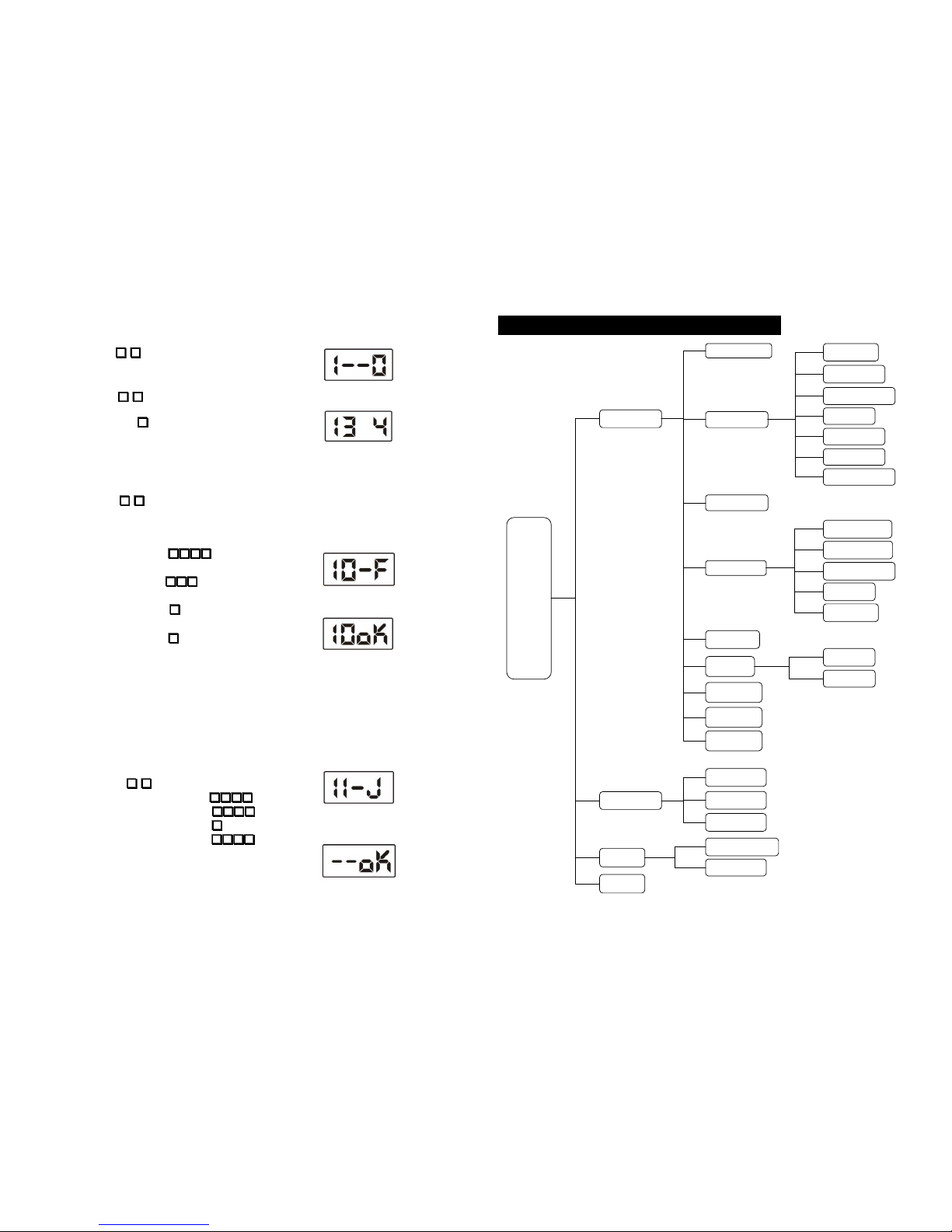
In the menu of P2, i nput
0
#
, enter the door station number
setting, it will show as P6 for the first time setting.
Input door station number, e.g.:
0 1 0 1
Input the gate-way port which connect to the door station, e.g.:
1
Press#button to confirm, it will automatically return to P2.
[Note] Door station’s No. is from 0001, Port No. of gate-way please
refer to theportof gate-way connected to door station.
(6)
On standby mode, pressF1button,enter function main menu
as P1 shows.
Input the system password:
2 0 0 3
.
If the password is correct, automatically enter P2. It means enter
the setting state successfully.
(1)
(2)
In the setting state, input
1
#
, then input
2
#
to clea r
all the indoor phone information. The LCD will shows as P3
during process.
(3)
(4)
If clearance successful, a long sound of “di” can be heard and
LCD shows as P4, press [*] button to back to menu of P2.
In the menu of P2, input
6
#
to clear the information in the
gate-way. After clearance, a long sound of “di” can be heard and
the LCD shows as P5, press [*] button to back to menu of P2.
(5)
Page 22
19
3. Indoor phone setting
I.Indoor phone digit
In the menu of P2, input
1
#
, t he LCD will shows as P7, the
information of indoor phone can be set here.
In the menu of P7, input
3
#
, the LCD will shows as P8.
The right number shows the current indoor phone digit. Input the
new number(2~4), and press#button to confirm.
[Note] You should choose the indoor phone digit first, then you can
proceed with theindoor phone number setting.
(7)
(8)
II. Single input mode
Then proceed with indoor phone information input,there are two input modes:Single input mode and
matrix input mode,user can choose what they need.
In the menu of P7, input
0
#
, the LCD will show as P9.
Input the indoor phone No., distributor No., port No., and ring No.
in turn.
◆ Indoor phone No: 2~4 digit No.(Digit is depended on the last
indoor phone digit) e.g.
0 1 0 1
◆ Distributor No:Input the distributor No. of indoor phone, valid
scope:001~254 e.g.
0 0 1
◆ Port No.:Input distributor port No. connecting to indoor phone
valid scope:1~4 e.g.
1
◆ Ring:This system offers 3 types of ring for user to choose,
input ring No.(1~3) e.g.
3
After finish, the LCD shows as P10, input next indoor phone No.
or press [*] to back to P7.
[Note] 1.Ringing isonlyheard when indoor phone is called.
2. When system’s ring is chord melody type, there are 3 types of
rings for chosen. If the door station is Dingdong ring type, it is
always “Dingdong”ring when choose 1-3.
(9)
(10)
III. Matrix input mode
[Note] This mode is only suitable for buildings with matrix structure,if every floor
has different quantityof apartment, then s
hould choose singleinput mode.
(11)
(12)
In the menu of P7, input
1
#
the LCD will show as P11.
◆ Start No: Input the start indoor phone No. e.g.
0 1 0 1
◆ End No: Input the last indoor phone No. e.g.
0 7 0 4
◆ Ring Type: Input ring number (1~3) e.g.
1
◆ Password:Input resident password e.g.
1 2 3 4
After finish, the LCD shows as P12, press [*] to back to P7.
[Note] The originalpassword is 1-2-3-4. Youcanrefer to “Appendix 2”
→
“Change password”to change it.
36
Appendix 1. LCD door station operation explanation
Enter System
Door Station
Indoor Phone
Single Input
Matrix Input
Clear Data
Bit
Alarm Setting
Card Setting
Register Single
Register Patrol
Delete Single
Delete All
Time & Date
PW unlock
Public PW
Private PW
Unlock Time
System PW
Private PW
Public PW
Operate Guide
Version No
Change PW
Help
Status
Menu
Upload
Download
Clear Gate-way
Card Info.
Language
Lift Setting
Page 23
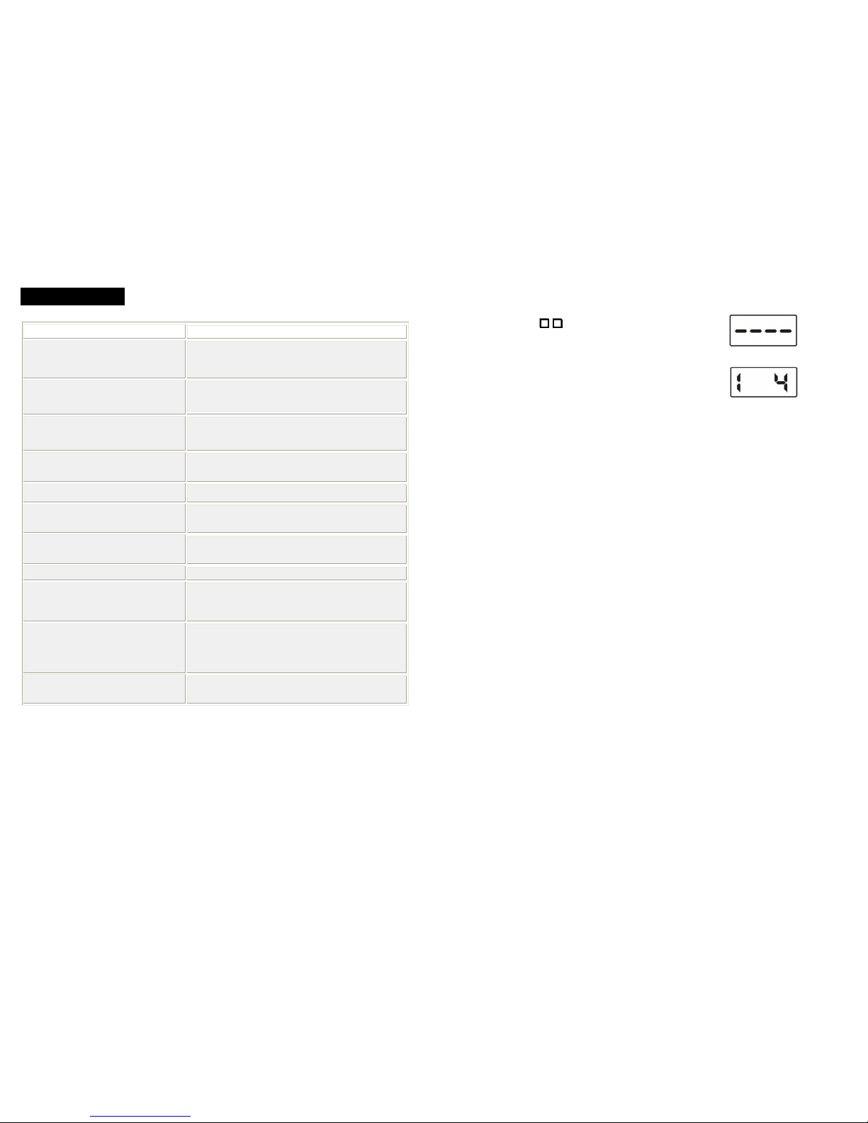
35
7. Trouble shooting
Malfunction phenomenon Elimination method
Unlocking error
A. Check the indoor switch button if it works properly.
B. Check the reverse diode linked to lock if it is connected correctly.
C. Check if the connection between lock and door station is correct or not.
Door station calling indoor phone, but indoor phone
doesn’t ring and doesn’t have image.
Check distributor address/number setting to see whether the
address/number is repeated or not.
Door station calling indoor phone, indoor phone rings
but has no image
Check whether PS port on gate way connects to ground or not.
Door station calling indoor phone, the image is not
clear.
Check whether one of the video lines is off or not. Or check whether the
video matching resistance is connected correctly or not.
Door station calling indoor phone, the volume is small. Check whethero neo fthe audio line is off or not.
Supply power for door station, the screen works but
the button does not work.
Check whether the button bounce back after pressing or not.
Door station calling
indoor phone, but indoor phone no.
doesn’t exist.
Check whether door station has set relative indoor phone no. or not.
Door station calling indoor phone fails. Check whether the wiring is correct or not.
Door station calling indoor phone, indoor phone
indicator light is showing busy, but indoor phone
doesn’t ring.
A. Check if the port on distributor connected to indoor phone is right or not.
B. check if the port on gate-way connected to door station is the same with
real setting.
Door station calling guard unit, no echo ringing, guard
unit rings, when pick up the handset of guard unit,
guard unit shows it is in conversation, but no voice
and
image.
A. Check if gate-way port set on door station is correct or not.
B. Check if the wiring through gate-way is right or not.
C. Check if the setting on switch is in accordance with reality, the switch
indicator light can be for your reference.
Guard unit has abnormal alarming. Check ifdoor station’s GS port ha sb eenconnected to GND port or not?
20
IV. Indoor phone data upload
[Note] This functionisfor upload indoor phone datasavedin door station to gate-waywhenin network.
Step 3. Testing basic functions
To test and check each device whether they work properly or not.
1. Door station calling indoor phone
Input room No. on door station to call indoor phone, indoor phone answers and unlocks the door.
Malfunction 1. Door station shows: Err2 (It means there is no response for calling).
● Check the wiring between door station and gate-way, distributor and gate-way
● Check if the DIP digit set in distributor is the same with the indoor phone setting on door station.
Malfunction 2. Door station enters ringing status, indoor phone doesn’t response.
●Check wiring between indoor phone and distributor.
2. Accessory door station calling indoor phone(only for system with accessory door station)
Dial room no. on accessory door station to call indoor phone, indoor phone answers and unlocks the door.
The problem phenomenon and solving method of the accessory door station is the same with the door station
3. Indoor phone monitor (only for video system)
Press monitor button on indoor phone to monitor the door station.
In th e menu o f P7, input
4
#
. The LCD will show as P13,
finally the LCD shows the upload result which is P14
Press [*] back to P2.
(14)
(13)
Page 24
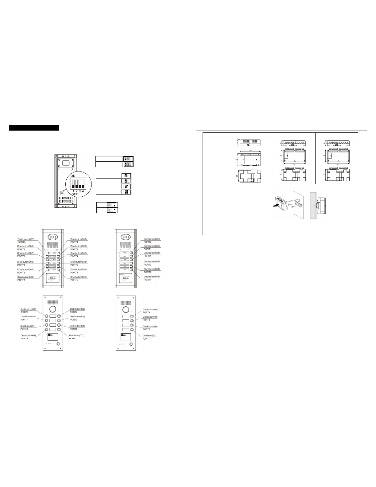
21
(Direct -call door station)
Step 2: Door station programming
■ Dip switch setting
Adjust the switches (if there is) according to the follow illustration:
■ Door station buttons list
The correspondence between door station buttons and distributor ports is as follows show:
1.Gate-way ports setting
PORT:[Door station1]
2.Buttons setting
Single columns buttons
3.Unlock time setting
5 sec.
1 sec.
PORT: [Door station 2]
Two columns buttons
Three columns buttons
Four columns buttons
34
Switch power, distributor, gate-way installation
Product name Switch power Distributor Gate-way
Dimension
Method 1. According to hole distance on
dimension map, install directly onto
the wall
Method 2. Put the upper buckle on the back
of these parts into the U shape track, and
push the buckle horizontally until the lower
buckle also enter the U shape track, please
refer to right picture.
Page 25
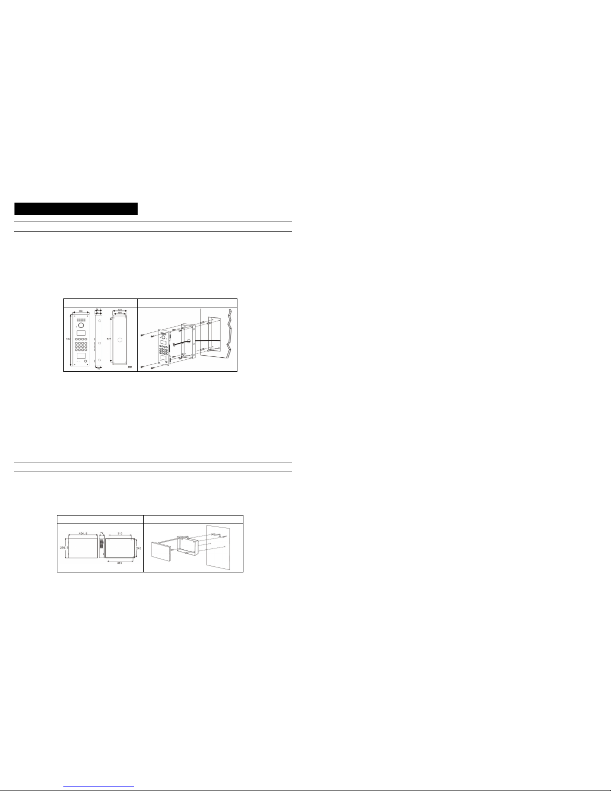
33
6. Product installation explanation
Door station installation
[Note] Pic ture for re fere nce onl y, pleas e re fer to the man ual att ache d wi th d oor sta tion for detailed insta llat ion .
Installation method◆
1. Make a square groove on proper position on wall or door according to the dimension of door station.
2. Put the door station back cover into the groove, according to the hole on the cover to make marks in the groove, and then drill holes.
3. Insert plastic expanding pipes into the holes in the groove, then install the back cover to the square groove with screw.
4. Install the top parts of door station to the back cover, use screws to fasten it from the screwhol es on the top part.
[Note] ifthedoor station is installed on iron door, no need toproceed step 2 and3,please directly weld the back coverintothe groove of iron
door.
Dimension Installation iconography
◆ Installation notes
① When drill holes on iron door or wall, please remember to be in accordance with the specific model and installation dimension.
② Before install the back cover of door station, please take care of the installation depth to ensure the surface of the door station is on
the same lever with the surface of iron door and wall in case there is big gap between the surface of door station and wall/iron door.
Flush installation type should be installed to the security door that is not to be opene③ d
Do not install door station in the environment of rain, wet, high temperature, and too much ash. Don’t install it near to ca④ usticity
objects.
⑤Installation height: Above the ground for 1100mm-1400mm. (Suggestion: W hen using video d oor station, the camera’s view scope
should be considered for the installation height to proper see the visitors’ face. People in wheelchair’s height should be also
considered.)
UPS power supply installation
◆ Installation method
1. Refer to the power supply dimension, mark the position of holes on back cover of power supply on the wall, and insert 2/3
length of screw into the wall.
2. Hang the power supply back cover to the screw.
3. Fasten power supply box by using two screws from the inside of power supply back cover, then put on the power supply front cover.
Dimension Installation iconography
22
Following setting especially for G9 door station (By remote control)
First , you must enter the system setting:
1.Press [FN] +password(4 bits) +[ENTER]
2.The door station will sound a long beep and the [DOOROPEN] LED will flash slowly.Itmeansenterthesystemsetting.
[Note] the original passwordis /1234/.
1. Memory/Information clearance (Only used in the first time programming)
1. Press [FN] + [DEL+] +[ENTER]
2. The door station willsound a long beep. And the [DOOR OPEN] LEDwill start to flash slowly. It means successfully toclean the indoor
phone data.
3. Press [FN] + [CLEAR] +[ENTER]
4. The door station will sound a long beep. And the [DOOR OPEN] LED will start to flash slowly. It means successfully to c lean the
gate-way data.
2. Door StationNo. setting
1. Press [SERVICE] + [UNLOCK], input door station number [apartment number(4 bits) + gate-way port number(1 bits)]
2. The door station will sound a long beep. And the [DOOR OPEN] LED will start to flash slowly. It means successful.
3. Indoor phone setting
1. Press [FN]+[REG-], [DOOROPEN] LED will flash quickly.
2. Press [CALL] button on the door station, system will sound a short beep.
3. Input "Distributor (3 bits)" + "Port number (1 bits)" + [ENTER]
4. If the door station sounds a long beep, that means the program is successful. While the [DOOROPEN] LED will still flashing quickly.
The program for another buttons is available by repeating step 2 and step3.
4. Indoor phone data upload
[Note] This functionisfor upload indoor phone data savedindoor station to gate-way when in network.
1. Press [FN] + [TIME] +[ENTER]
2. The doo r station will sound a long beep. And the [DOOR OPEN] LED will start to flash slowly. It means successfully to upload the
indoor phone data.
Step 3. Testing basic functions
To test and check each device whether they work properly or not.
1. Door station calling indoor phone
Press call button on door station, the corresponding indoor phone will ring, then answer the call and unlock the door.
Malfunction 1. Door station sounds three short “di”.
● Check the wiring between door station and gate-way, distributor and gate-way
Malfunction 2. Door station enters ringing status, indoor phone doesn’t response.
●Check wiring between indoor phone and distributor.
2. Accessory door station calling indoor phone(only for system with accessorydoor station)
Press call button on door station to call indoor phone, indoor phone answers and unlocks the door.
The problem phenomenon and solving method of the accessory door station is the same with the door station
3. Indoor phone surveillance (only for video system)
Press monitor button on indoor phone to monitor the door station.
Page 26
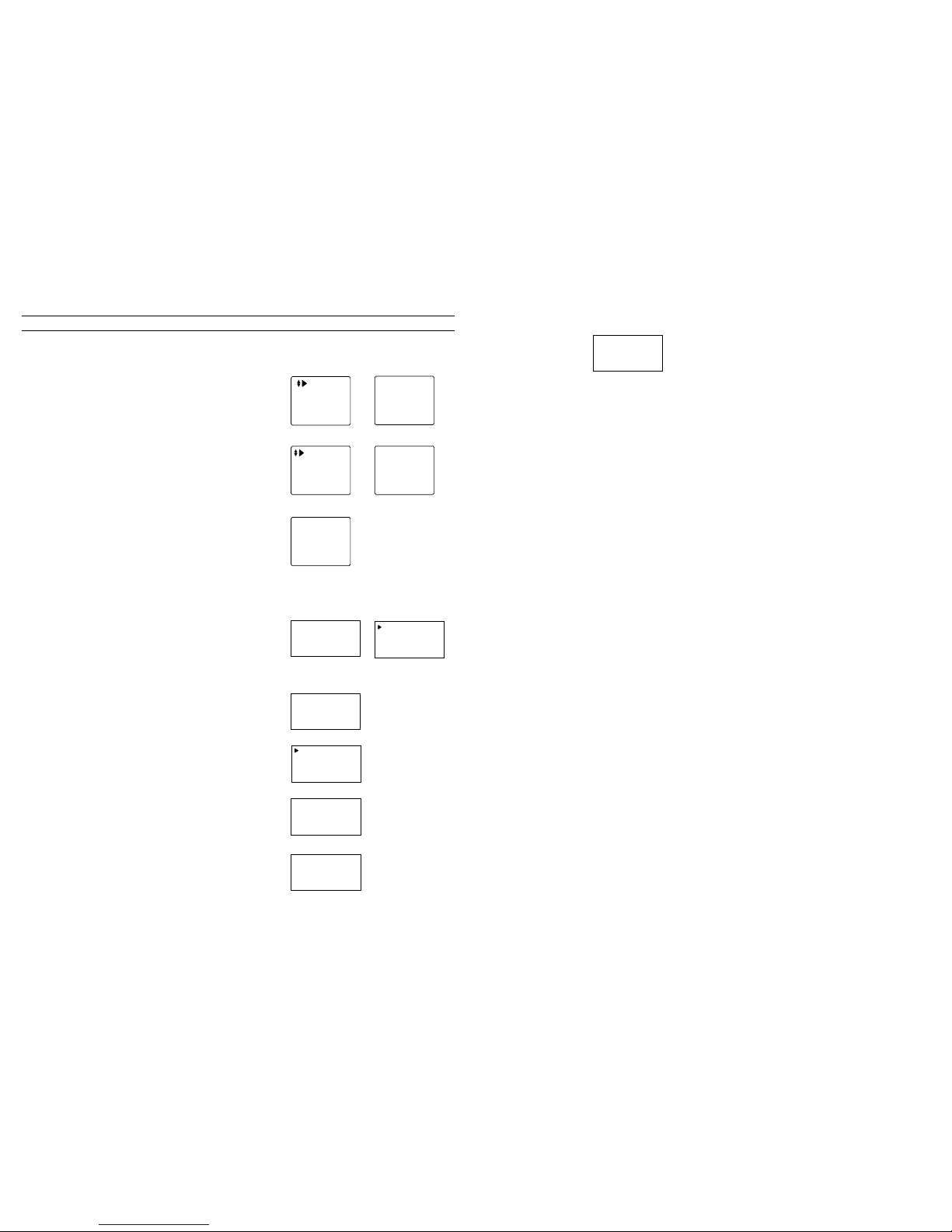
23
Network system programming
According to building programming steps, have all door stations programmed, and then proceed network system programming.
Step 1. Perimeter gate station setting
Step 2. Guard unit setting
Cleanup record
Done?
In P2,press [down] key to choose“Cleanup rec .”,
press “confirm”
key , LCD shows P3,and press “confirm” key again,
clear guard
unit data.
(3
)
1.Data clearance
(
For first time programming
)
1. Add
2. Download
3. Cleanup
In P2,press[down] key to “Project Set”, press confirm,
LCD
shows P4
(4
)
In P4, press[down]key to choose “Cleanup”, press conf irm key,
LCD sh
ows P5
Done?
Press confirm key,LCD shows cleanup status,
after finish, show
P6,then back to P4
(5
)
Clean up
(6
)
Press [confirm]key,LCD shows P1, input code: 1-2-3-4-5-6-7-8
[Note]
This password isinitial code
Input Password:
1.Guard No.
2.Project Set
3.Cleanup rec
4.Software VER
If password is right, will enter P2 directly
(1)
(2)
Enter System
Change PW
Help
On standby mode, press F1 to enter main menu of P1, choose
“Enter System” and press # to confirm.
System Password:
_ _ _ _
LCD shows P2,enter system password:2-0-0-3
[Note] This password is theoriginal one
If the password is correct, enter P3 automatically , choose
perimeter gate station No. and press # to confirm
Perimeter Gate
Card
Time & Date
PW Unlock
(1
)
(2
)(3)
LCD shows P4,enter here the perimeter gate station No. and
switch port No., then press [*] to back to P3
[Note] The validscopefor perimeter gate station is 00~09.
Perimeter Gate:
— — — —
Switch Port:
—
(4
)
e.g.: Input the data according to left Picture and press # to
confirm, after successful registration, shows P5
Perimeter Gate:
0001
Switch Port:
1
(5
)
32
4. After finishing setup form, download it to switch, when download finishes, will show below:
Step 3: Test basic functions
1. Perimeter gate station calling guard unit
Press # key on perimeter gate station to call guard unit, and guard unit answers.
2. Door station calling guard unit
Press # key on door station to call guard unit, guard unit answers
3. Intercom between indoor phone and guard unit.
Pick up indoor phone handset (if it is hands-free indoor p hone, please press “talk” button), press “call” button to call guard unit,
guard unit answers; Pick up the handset of guard unit, dial room No. to call indoor phone, indoor phone answers.
4. Perimeter gate station call indoor phone
Dial room No. on perimeter gate station (For example: Calling unit 001, room no. 301, you should dial “00010301”. Note: For the 3
digits door station, you should add 0 in the front to make the door station digits to be 4-digit.)
Successfully
0006 Bar
Page 27
31
5. Data upload, after upload, sh ow as below:
6. Second confirmed door station setting (setting method is the same as door station step 1-4), setting picture f or step 2
is as below.
Step 3: Basic function test
1. Door s tation calling indoor phone
Dial room No. like 203 on door station to call indoor phone, indoor phone answers and unlock the door.
2. Second confi rmed door station calling indoor phone.
Dial indoor phone No. to call indoor phone, indoor phone answers and unlock the door.
3. Indoor phone surveillance (only apply in video system)
Press the “surveillance" key to watch the door station status
Programming second building
The programming method is the same with the first building.
■ Networksetting:
Step 1: Perimeter gate station setting
Set perimeter gate station No. and switch port on perimeter gate station.
Step 2: Guard unit setting
1. Clear guard unit record and setup form.
2. Setting guard unit No.
3. Add setup form as below:
Type Code Switch port Distance Gate-way code Gate-way port
Door station 0101 01 150m 01 1
Door station 0102 01 150m 01 2
Door station 0201 02 300m 01 1
Door station 0202 02 300m 01 2
Perimeter gate station 0001 05 300m —— ——
Guard unit 01 03 300m —— ——
Perimeter Gate :
0001
Switch Port:
5
Door station No.
0002
Gate-WayPort :
2
Seq. No.:015
Indoorphone.: 80 1
Distributor 00 5-1
R
ing Type:2
24
Guard No:1
New:
Press “back” key to return toP2,choose “guard unit No. setting”,
press confirm key, LCD shows P7
(7
)
1. Add
2. Download
3. Cleanup
In P2, press
[down] key to select system set, press confirm key
and LCD shows P9
(9)
In P9, select “add” and press confirm key, LCD shows P10
1.Type:Door
2.No:0001
3.SwitchPort:00
4.Dist: 0 m
(10)
2. Setting guard unit No.
[Note] If thereisonly one guard u
nit in network,thenthe guard unit
number is 1.
According to hint, input newgu ardunit No.,press “confirm” key,
LCD shows P8
,
then back to P2
Guard No:1
New:2
Save OK
(8
)
3. Add setting form
In P10, press [down] key to check each setting informatio
n, then
it comes to P11
5.Gate No:01
6.Gate Port:01
7.Previous
8.Next
(11)
[Note] This formcollects information fromdoor station in the building,guardunit and perimeter gate stationin network.
Then
download thissettingform
to switch tomakesyst
em work.
In P10,
press[down]key to select “No.”, use number key to enter
door station No., setting as P12
[Note] Door stati
on No. canbeset according to building apartment
No.
1.Type:Door
2.No:0101
3.SwitchPort:00
4.Dist: 0 m
(12)
After No. setting, press [down] key to select “switch port”,
enter
switch port No.(The p ort No. which has been connected to ga te-
way
terminals ),as P13 shows.
S
etting door station information
1.Type:Door
2.No:0101
3.SwitchPort:01
4.Dist: 0 m
(13)
After setting the
switch port, press [down] key to select “dist”,
enter the distance(from door station to switch), as P14 shows.
0: 0m 1: 150m 2: 300m 3: 450m
4: 600m 5:750m
1.Type:Door
2.No:0101
3.SwitchPort:01
4.Dist: 150 m
(14)
2.No:0101
3.SwitchPort:01
4.Dist: 150 m
5.Gate No:01
(15)
After distance s etting,press [down] key t
o select "gate No.”.
Enter gate-way No. setting, shows as P15
3.SwitchPort:01
4.Dist: 150 m
5.Gate No:01
6.Gate Port:1
(16)
After gate way No. setting, press [down] key to select “gate port” ,
enter gate port No. as P16 shows.
Till now one door station’s information setting is completed, press
[#] to save. Following the above steps to set another door station
.
Page 28
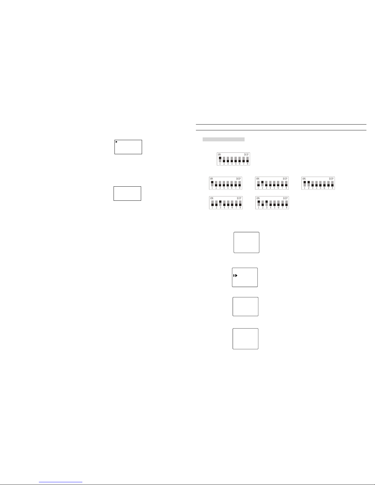
25
In P10,
select setting equipment: 0: doo r station 1:guard unit
2:perimeter gate station
Example enter 2, and LCD shows P17
1.Type:Perimete
2.No:0001
3.SwitchPort:00
4.Dist: 0 m
(17)
Then proceed with perimeter gate station and guard unit setting.
Then set perimeter gate s tation (guard unit) No., s witch port No.
and dis
tance, setting is just like door station setting, press[#] to
save when finish.
4.Download setting form
Press [back] key to back to P9, press[down] k ey to select
“download setting form”, press [confirm] key,
after download,
LCD shows P18.
Successfully
0012 Bar
After successful download, back to P9
(18)
30
System Programming
■ Unitdoor station programming
First program first building
Step 1: Hardware setting
(1)Set DIP of 4300 gate-way to 001 as below
(2)Set the DIP digit for distributors (4110 & 4110S) in the unit respectively from 001-005
(001) (002) (003)
(004) (005)
Step 2: Door station setting(first set on main door station)
1. Clear data
2. Door station No. setting, shows as below
3. Indoor phone information setting
(1)Indoor phone number digit setting, show as below:
(2)Input indoor phone information, here adopts matrix input mode (From 1stto 7thfloor).
And the 8thfloor should be set by single input, show as below:
Indoor phone:801
Distributor: 005
Port No.: 1
Ring Type:2
Start No.:101
End No. :702
Ring Type:2
Password:
* ***
2 bits
3 bits
4 bits
3 bits Current
Door station No.
0001
Gate-Way Port :
1
Page 29
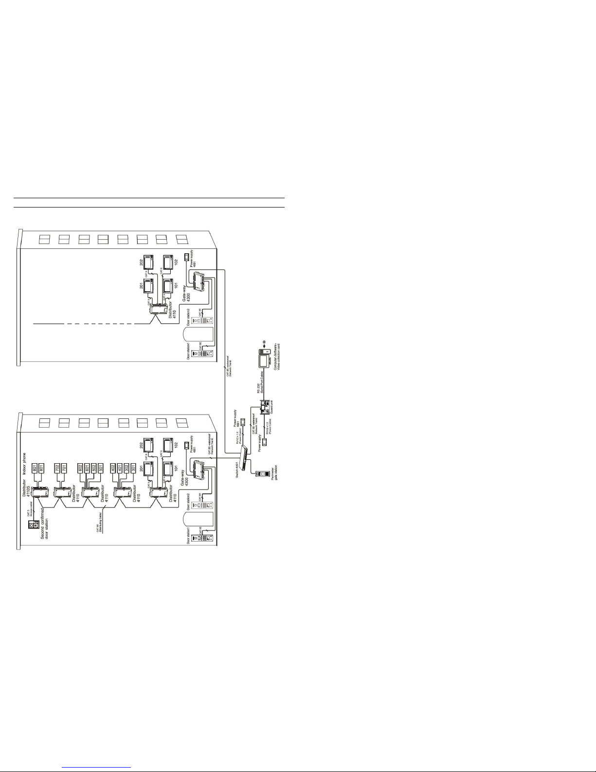
29
System wiring diagram
[Note] Please referto“3.Productwiringdiagram”for detailed wiring diagram.
26
Step 3. Basic function tests
1. Perimeter gate station call guard unit
Press # on perimeter gate station to call guard unit and guard unit answers.
Malfunction 1, perimeter gate station shows: Fail-2.
● Check the wiring between perimeter gate station and switch.
Malfunction 2. Perimeter gate station shows: Fail-11.
● Check wiring between guard unit and switch.
Malfunction 3. Guard unit ringing, but no image, perimeter gate station no ringing.
● Check whether the indicator light on switch for guard unit and perimeter gate station port is on or off. If the indicator light is on,
but it is not the same as the wiring port, check the setup form of perimeter gate station and guard unit, check whether they are
in accordance with the actual wiring.
2. Door station(LCD)calling guard unit
Press # key on door station to call guard unit, and guard unit answers.
Malfunction 1. Door station shows: Fail-2
● Check wiring between door station and gate-way.
Malfunction 2. Door station shows : Fail-9.
● Check wiring between switch and gate-way
Malfunction 3. Door station shows: Fail-11.
● Check wiring between guard unit and switch
Malfunction 4. Guard unit ringing, but no image, door station no ringing
● Check whether the indicator light on switch for guard unit and gate-wayport is on or off. If the indicator light ison, but it is not the
same as the real wiringpo rt, check the setup form ofdoor station and guard unit, check whether they are in accordance with the
actual wiring or not.
Malfunction 5. The door station no. shows on the guard unit is not the same with reality.
● Check whether the door station setup form is in accordance with the actual wiring or not.
2-2. Door station(LED)calling guard unit
Press # key on door station to call guard unit, and guard unit answers.
Malfunction 1. Door station shows: Err2
● Check wiring between door station and gate-way.
Malfunction 2. Door station shows: Err9
● Check wiring between switch and gate-way
Malfunction 3. Door station shows: Err11
● Check wiring between guard unit and switch
Malfunction 4. Guard unit ringing, but no image, door station no ringing
● Check whether the indicator light on switch for guard unit and gate-wayport is on or off. If the indicator light is on,but it is not the
same as the real wiringpo rt, check the setup form ofdoor station and guard unit, check whether they are in accordance withthe
actual wiring or not.
Malfunction 5. The door station no. shows on the guard unit is not the same as reality.
● Check whether the door station setup form is in accordance with the actual wiring or not.
2-3. Direct-call door station calling guard unit
Press # key on door station to call guard unit, and guard unit answers.
Malfunction 1. Door station sounds short “di” “di” “di”.
● Check wiring between door station and gate-way.
Page 30
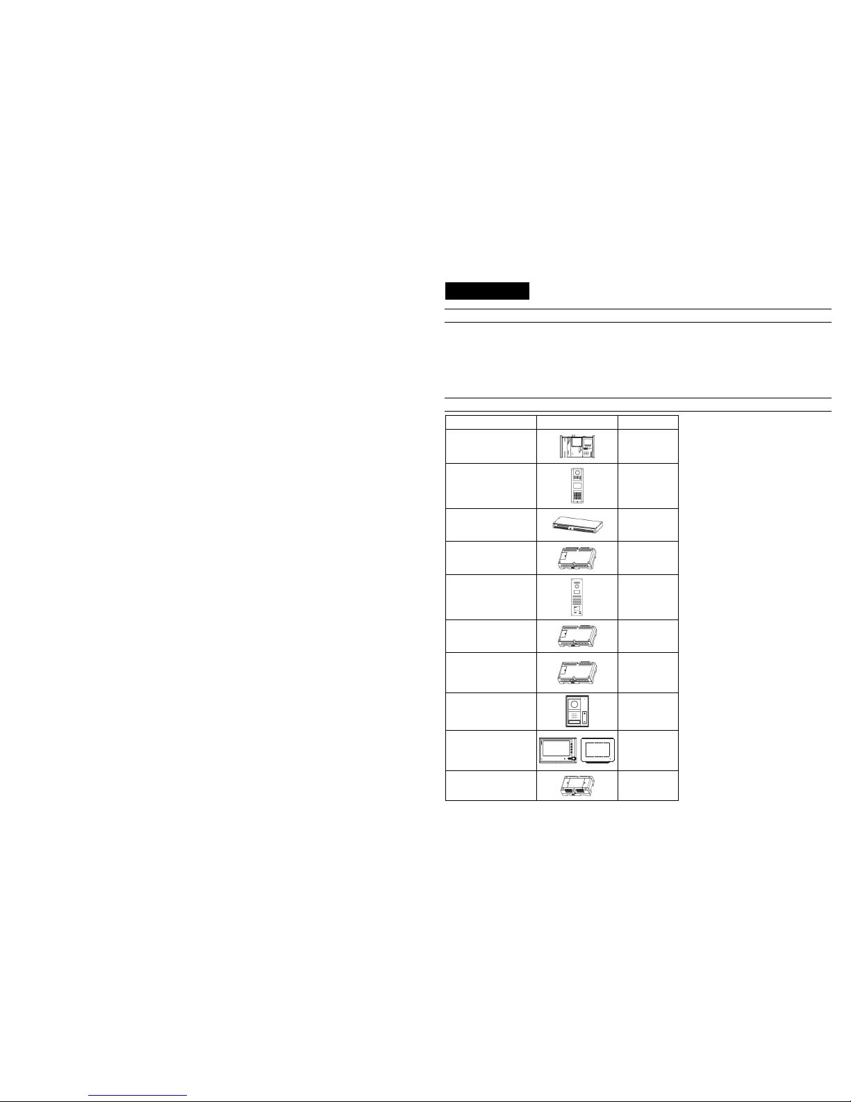
27
● Check wiring between switch and gate-way
● Check wiring between guard unit and switch
Malfunction 1. The door station no. shows on the guard unit is not the same as reality.
● Check whether the door station setup form is in accordance with the actual wiringor not.
3. Intercom between indoor phone and guard unit
Pick up the handset of indoor phone (if it is hands-free indoor phone, press “talk” button), then press “call” button to call guard unit,
guard unit answers and intercom with each other. Pick up guard unit handset, dial the indoor phone No. to inter
com with the indoor
phone.
Malfunction 1. Indoor phone No. shows on guard unit does not in accordance with the real indoor phone.
● Check whether the indoor phone data/information from the door station has been uploaded to the gate-way or not.
4. Perimeter gate station calling indoor phone
Dial room No. on perimeter gate station and call indoor phone, indoor phone answers and unlock thedoor.
28
5. Project case
Customer requirement description
1. There is a community with two buildings, each building has 8 floors, from 1stto 7thfloor, there are2residents in each floor, and in 8
th
floor there’s only 1 resident.
2. There are two door stations be installed at the front door and back door.
3. From 1
st
to 7thfloor, each resident have an indoor phone. While in 8thfloor there are two indoor phones and a second confirmed door
station.
4. There is a guard unit at the managing center, and there isa perimeter gate station at the main entrance.
Components
Product Picture quantity
Guard unit
6805
1
Perimeter gate station
6831
1
Network switch
4401
1
Gate-way
4300
2
Door station
2608
4
Distributor
4110
8
Apartment distributor
4110S
2
Second confirmed door
station
5805
2
Indoor phone
Cygni / Lyra
32
Switch power supply
4001
4
 Loading...