

Intelligent Charging Limited IC48V Operator's Manual

IC48V Battery Charger/Analyser
Operator Manual
Doc: DWG1060-12-R3 IC48V Operators manual.odt Page 1 of 58 Copyright Material of Intelligent Charging Limited © 2015
Printed On : 14/06/17
IC48V
BATTERY CHARGER
AND CAPACITY TESTER
OPERATORS MANUAL

IC48V Battery Charger/Analyser
Operator Manual
Table of Contents
1 Manual Revision History............................................................................................................4
2 Equipment Description..............................................................................................................5
2.1 General.............................................................................................................................5
2.1.1 Charging Modes..........................................................................................................5
2.1.2 Capacity Testing Modes...............................................................................................6
2.2 Component Parts...............................................................................................................8
2.3 Installation........................................................................................................................8
2.4 Front Panel Controls And Indicators....................................................................................9
2.5 Rear Panel Controls And Indicators....................................................................................11
3 Cell Monitor Interface..............................................................................................................12
3.1 General............................................................................................................................12
3.2 Charging With The Cell Monitor.........................................................................................12
3.2.1 Constant current charge............................................................................................12
3.3 Discharging With The Cell Monitor.....................................................................................13
3.3.1 Capacity Testing To Target Or Time...........................................................................13
3.3.2 Automatic Cell Balance...............................................................................................13
3.4 Monitor Only Mode...........................................................................................................13
3.5 Normal Charge or Capacity Test Mode...............................................................................13
3.6 Cell Monitor Extended Display Reference...........................................................................13
3.7 Printing Data When Using The Cell Monitor........................................................................14
3.8 Cell Number Reversal.......................................................................................................15
3.9 Cell Monitor Specifications................................................................................................15
4 Equipment Menu Operation.....................................................................................................16
4.1 Main Menu.......................................................................................................................16
4.2 Charging Menu.................................................................................................................17
4.3 Capacity Testing Menu......................................................................................................18
4.4 Library Menu....................................................................................................................19
4.5 Settings Menu..................................................................................................................20
4.6 Cell Monitor Menu............................................................................................................21
4.7 Process Operation Menu...................................................................................................22
5 Connecting A Battery...............................................................................................................23
6 Connecting The Flying Lead Cell Monitor..................................................................................25
7 Connecting The Crown............................................................................................................25
8 Battery Charge Operation........................................................................................................26
8.1 Constant Voltage Charge..................................................................................................26
8.2 Constant Current Charge..................................................................................................27
8.3 Multi-Step Constant Current Charge..................................................................................28
8.4 Constant Current Charge Using Cell Monitor.......................................................................29
8.5 Performing A Charge........................................................................................................30
8.5.1 CHARGE FROM A LIBRARY ENTRY..............................................................................30
8.5.2 CHARGE FROM MANUAL DATA...................................................................................30
8.5.3 CHARGE FROM PREVIOUS DATA................................................................................30
9 Battery Capacity Test or Discharge Operation...........................................................................31
9.1 Capacity Test To 100%....................................................................................................31
Doc: DWG1060-12-R3 IC48V Operators manual.odt Page 2 of 58 Copyright Material of Intelligent Charging Limited © 2015
Printed On : 14/06/17

IC48V Battery Charger/Analyser
Operator Manual
9.2 Capacity Test To Target Voltage........................................................................................32
9.3 Capacity test Using Cell Monitor........................................................................................33
9.4 Automatic Cell Balancing...................................................................................................34
9.5 Full Battery Discharge.......................................................................................................35
9.6 Performing A Capacity Test...............................................................................................36
9.6.1 Capacity Test or Discharge From A Library Entry.........................................................36
9.6.2 Capacity Test or Discharge From Manual Data.............................................................36
9.6.3 Capacity Test or Discharge From Previous Data...........................................................36
10 Creating Or Modifying Library Entries.....................................................................................37
10.1 Data Entry Procedure......................................................................................................37
10.2 Entering Charge Data.....................................................................................................37
10.3 Entering Discharge Data.................................................................................................39
11 Process Mode........................................................................................................................40
11.1 Overview Of Operation...................................................................................................40
11.2 Process Menu.................................................................................................................40
11.2.1 Renaming a process.................................................................................................41
11.2.2 View or Edit A Process.............................................................................................41
11.3 Process Execution...........................................................................................................42
11.4 Process Termination.......................................................................................................42
12 Calibration............................................................................................................................44
12.1 Equipment Required.......................................................................................................44
12.2 Calibration Equipment Connection...................................................................................44
12.3 Check Procedure............................................................................................................44
12.4 Making Calibration Adjustment........................................................................................45
12.5 Reviewing Calibration Date.............................................................................................46
13 Miscellaneous Unit Functions..................................................................................................47
13.1 Description Of Stop Codes...............................................................................................47
13.2 Print Or Display Previous Operation Results......................................................................49
13.3 Changing The Date Format And Date Time......................................................................49
13.4 Modifying Display Intensity.............................................................................................50
13.5 Printing battery serial number.........................................................................................50
14 Service And Maintenance.......................................................................................................51
14.1 Calibration.....................................................................................................................51
14.2 Cleaning........................................................................................................................51
14.3 Battery Backup...............................................................................................................51
14.4 Printer Care....................................................................................................................52
14.4.1 Door Latch..............................................................................................................52
14.4.2 Paper Feed Button...................................................................................................52
14.4.3 Paper Roll Replacement...........................................................................................53
14.4.4 Ribbon Cartridge Replacement.................................................................................53
14.4.5 Consumables Available.............................................................................................54
15 Specifications........................................................................................................................55
16 Product Disposal Instructions.................................................................................................57
17 Product Warranty..................................................................................................................58
Doc: DWG1060-12-R3 IC48V Operators manual.odt Page 3 of 58 Copyright Material of Intelligent Charging Limited © 2015
Printed On : 14/06/17

IC48V Battery Charger/Analyser
Operator Manual
1 Manual Revision History
Rev Date Description
1 17-09-2013 Written from an IC50A manual.
2 21-07-2015 Formatting changes..
3 21-04-2016 Corrected maximum charge current at 12V
Doc: DWG1060-12-R3 IC48V Operators manual.odt Page 4 of 58 Copyright Material of Intelligent Charging Limited © 2015
Printed On : 14/06/17

IC48V Battery Charger/Analyser
Operator Manual
2 Equipment Description
2.1 General
The Battery Charger Analyser is an electronically controlled combined universal battery
charging unit with built in battery analysing (capacity testing) capabilities. It is housed
in a metal enclosure designed for bench mounting. As it is supplied it is designed to
work on a 240V supply. It can be operated on a 115V supply but it will exceed the fuse
rating if used on high charge rates.
Equipment control is via an interactive 253 x 32 dot matrix display and data entry is via
a 16-key keypad. Operating modes and functions are selected by the use of a simple
menu system. Access to charging and testing operations is performed by either entry of
eight digit battery library names, repeat of last charge or capacity test or new manual
parameters. During operation the display will show the instantaneous values of battery
voltage, current and time elapsed through the selected program.
Process modes can be created where complete unattended charging, capacity testing
and final charging can be performed. Up to 6 different charge or capacity test steps can
be created and up to 4 process programs can be stored in the unit. Each process step
has an optional delayed start for resting the battery and also each step can sound the
alarm with or without a pause in operation. The process is simply continued by pressing
a key on the keypad.
Battery data is stored internally in the units non-volatile memory. The operator can add
and modify this list by entering the details of the battery to be included on the display
and keyboard. Alphanumeric digits, up to a maximum of 8 digits, identify Battery library
entries
Batteries are connected to the front of the unit by means of two individual high current
connectors. Connection to the battery has to be made via the appropriate connectors
for that battery. The unit is supplied with M8 ring crimps that must have the
appropriate connector for the battery type being tested fitted.
The IC48V can: -
Charge 12V at 80.0A
Charge 24V batteries at 80.0A
Charge 48v batteries at 40.0A
Capacity Test 12V Batteries at 100.0A
Capacity test 24V batteries at 80.0A
Capacity test 48v batteries at 40.0A
The unit contains a high flow rate fan to extract the heat energy generated internally
when running in capacity test mode.
2.1.1 Charging Modes
CONSTANT VOLTAGE CHARGE
Doc: DWG1060-12-R3 IC48V Operators manual.odt Page 5 of 58 Copyright Material of Intelligent Charging Limited © 2015
Printed On : 14/06/17

IC48V Battery Charger/Analyser
Operator Manual
Where the battery is charged at a reducing current when the constant voltage
threshold is met. Parameters for this mode are maximum charge time, optional
minimum current to stop charge and a current threshold, which can detect a
potentially faulty battery.
CONSTANT CURRENT CHARGE WITH TOP UP CHARGE
Where battery is charged at a constant current until a terminal voltage is met, at
this point it can be charged for an additional time at a user set current. The
overcharge voltage is set in this mode to prevent overcharging of the battery.
MULTIPLE STEP CONSTANT CURRENT CHARGE
Up to 4 constant current steps can be implemented for the charge cycle. this
mode also has an overcharge voltage setting to prevent overcharging of the
battery. Charge current can be set to zero for “rest” periods between charge
steps.
CONSTANT CURRENT USING CELL MONITOR
In this mode the battery will be charged at constant current with the charge
switching to the top up charge (if required) when all the cells reach the target
voltage specified.
2.1.2 Capacity Testing Modes
CAPACITY TEST TO 100 PERCENT
This mode will discharge the battery connected at the current specified for the
test duration specified thus reporting the battery capacity is 100% or more. The
capacity test will be stopped if the target voltage is reached before the full test
time has elapsed. During the capacity test and when it is terminated the display
will show the amount the capacity test is complete as a percentage.
CAPACITY TEST TO TARGET VOLTAGE
This mode will discharge the battery down to the terminal voltage specified thus
reporting the actual percentage capacity. The capacity test will be stopped if the
target threshold voltage is reached before the full test time has elapsed. During
the capacity test and when it is terminated the display will show the amount the
capacity test is complete as a percentage.
CAPACITY TEST WITH CELL MONITOR
This mode will discharge the battery connected at the current specified for the
test duration specified thus reporting the battery capacity is 100% or more. The
capacity test will be stopped if any cell reached the cell target voltage before the
full test time has elapsed. During the capacity test and when it is terminated the
display will show the amount the capacity test is complete as a percentage.
AUTOMATIC CELL BALANCE
This mode is designed to discharge the battery down to zero volts, where when
any cell reached zero volts a balancing resistor will automatically be placed
across it. When the battery total voltage reached near zero all the remaining
balancing resistors will be applied.
FULL DISCHARGE
Doc: DWG1060-12-R3 IC48V Operators manual.odt Page 6 of 58 Copyright Material of Intelligent Charging Limited © 2015
Printed On : 14/06/17

IC48V Battery Charger/Analyser
Operator Manual
This mode will do a basic discharge of the battery at the current specified for the
time specified.
The unit can be set so that a predefined charge or capacity test can be scheduled to start at
up to 99.9h in the future. And if during this time the power is lost to the unit, such as a power
outage, the unit will continue to count down when the power is restored. Note: If the power
outage resumes after the elapsed time has been passed the predefined charge or capacity test
will not be executed.
The unit contains the software that will allow it to be calibrated by the end user doing away
with the need to send the unit to a service centre for periodic calibration. The re-calibration
process only takes a few minutes and this is done without the need to access the internals of
the unit.
The printer when fitted allows the operator to print hard copies of the charge and test results
upon completion of the test. This report can be used to complement the service schedule by
providing full traceability.
Doc: DWG1060-12-R3 IC48V Operators manual.odt Page 7 of 58 Copyright Material of Intelligent Charging Limited © 2015
Printed On : 14/06/17
IC48V Battery Charger/Analyser
Operator Manual
2.2 Component Parts
Upon receipt of your new battery charger analyser unpack and check that all items are
present in the containing box.
STANDARD ITEMS
One IC48V Battery Charger Analyser
One power cord
One Set (+ve & -ve) standard battery leads.
One paper Copy Operators Manual
Certificate Of Conformity
Calibration Certificate
OPTIONAL ITEMS
Cell Monitor Interface
Cell Monitor Crown (to suit battery specified).
Battery specific connectors.
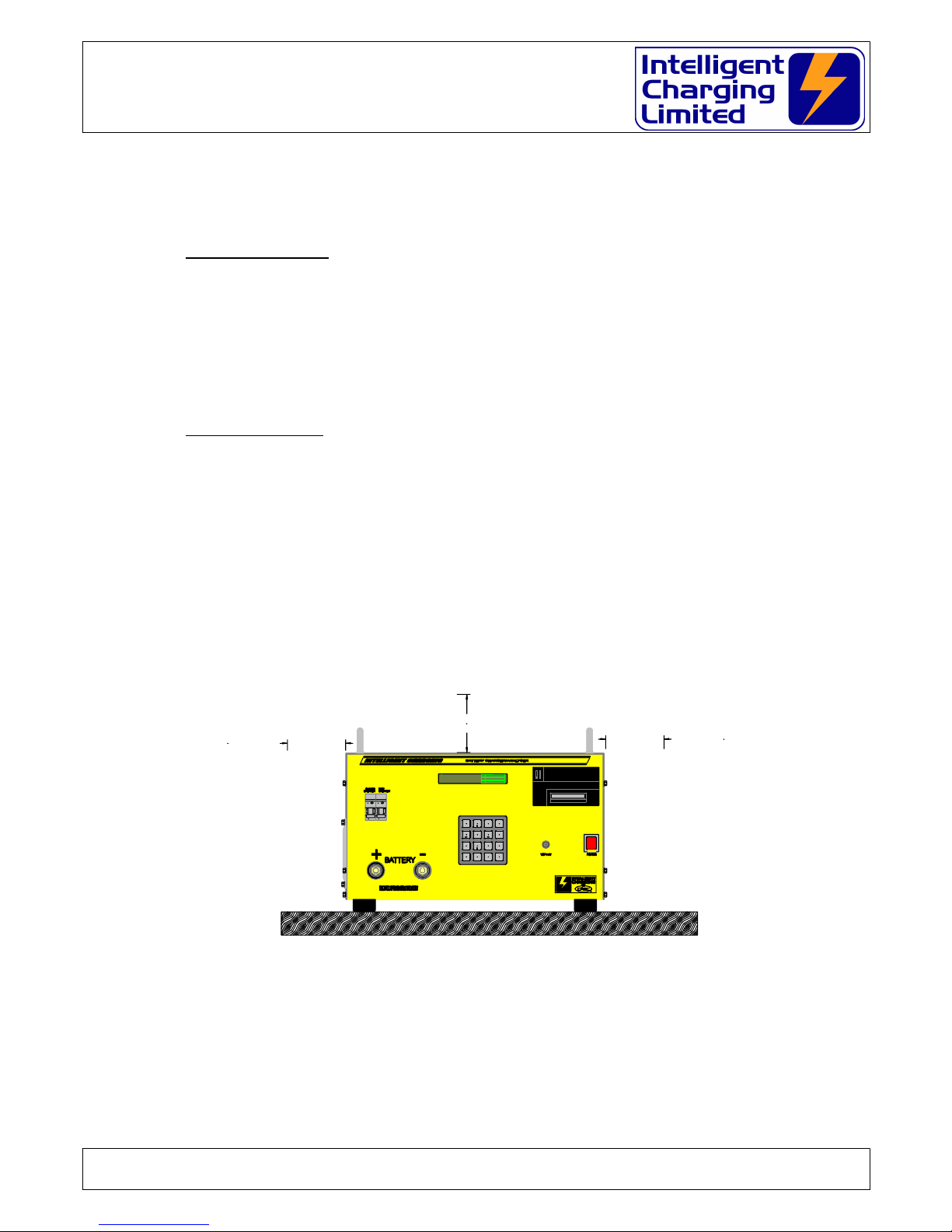
2.3 Installation
The Battery Charger Analyser should be mounted on a level surface such as a
workbench or sturdy shelf above the batteries with a loading weight of at least 50Kg.
The unit should be sited so that at least 10cm of airspace is available all round the sides
and top of the unit to allow free movement of air required for cooling.
Doc: DWG1060-12-R3 IC48V Operators manual.odt Page 8 of 58 Copyright Material of Intelligent Charging Limited © 2015
Printed On : 14/06/17
MEM
B63
ON
OFFIO
MEM
B63
ON
OFFIO
859 A
6 B
31 2
*
CLR
0
#
ENT
C
.
4
7
MB73+ MAIN A CHARGE
7-05-2006 16:30:15 B TEST
C SETTINGS
100.0 mm
100.0 mm
100.0 mm
IC48V Battery Charger/Analyser
Operator Manual
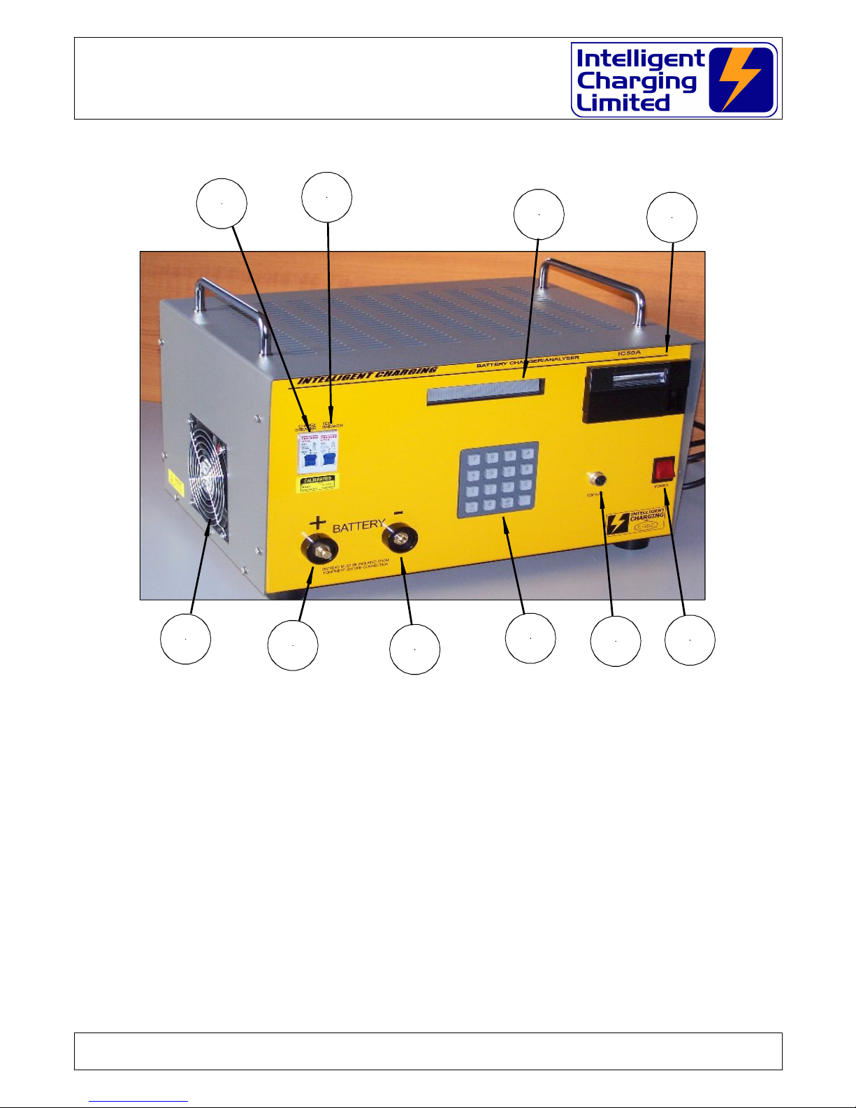
2.4 Front Panel Controls And Indicators
(A) – DISPLAY
All battery charger indications are made on this 256 x 32 dot matrix vacuum fluorescent
display.
(B) - BUILT IN PRINTER
If fitted the optional 24 column printer. On the non printer models this will be a
blanking plate.
(C) - MAINS POWER SWITCH
Pressing this switch activates mains power. It will illuminate to indicate power is being
applied to the unit.
Doc: DWG1060-12-R3 IC48V Operators manual.odt Page 9 of 58 Copyright Material of Intelligent Charging Limited © 2015
Printed On : 14/06/17
G
F
E
D
C
B
A
I
H
J

IC48V Battery Charger/Analyser
Operator Manual
(D) - AUXILLIARY CONNECTOR
This 6 pin connector is the RS232 and power connector for the cell monitoring unit. It
can also be used for remote control operation with PC based software.
(E) – KEYPAD
All battery charge and capacity test functions are activated via this 16 key keypad.
(F) - NEGATIVE BATTERY TERMINAL
Connection of the negative battery lead is made to this terminal.
(G) - POSITIVE BATTERY TERMINAL
Connection of the positive battery lead is made to this terminal.
(H) - HEAT EXCHANGER EXHAUST FAN
During use the unit absorbs electrical power, which it turns into heat, this fan exit is
where the heat is extracted from the unit. It is important that it is not obstructed.
(I) & (J) - CHARGE & CAPACITY TEST CIRCUIT BREAKERS
The circuit breakers are fitted to prevent high currents from being driven into the
battery or into the unit should a fault condition occur. Always ensure that the circuit
breaker is in the ON position before starting a charge or capacity test.
WARNING
NEVER SWITCH THE CIRCUIT BREAK TO ON WHEN THE UNIT IS PERFORMING A
CHARGE OR CAPACITY TEST AS SEVERE DAMAGE MAY OCCUR TO THE BATTERY OR THE
EQUIPMENT
ALWAYS PRESS STOP FIRST
If the circuit breaker operates during a charge immediately press STOP and remove
power from the unit and disconnect the battery.
Operation of the circuit breaker is an indication of a fault and the unit will need to be
checked before using.
Doc: DWG1060-12-R3 IC48V Operators manual.odt Page 10 of 58 Copyright Material of Intelligent Charging Limited © 2015
Printed On : 14/06/17
IC48V Battery Charger/Analyser
Operator Manual
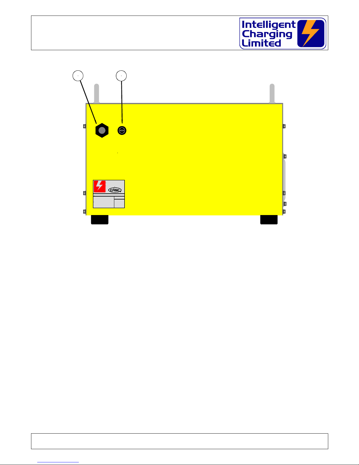
2.5 Rear Panel Controls And Indicators
(K) - Mains Lead
This is the entry point for the power lead into the unit. Always check that the lead is not
damaged before use.
(L) - Mains Fuse.
The mains fuse fitted to the IC48V is 16.0A Slow Blow 1¼”
Doc: DWG1060-12-R3 IC48V Operators manual.odt Page 11 of 58 Copyright Material of Intelligent Charging Limited © 2015
Printed On : 14/06/17
MAINS 220V-240V 50Hz/60Hz 2.4KW
REPLACE ONLY WITH SAME TYPE FUSE 13A S/B
SERIAL No:
INTELLIGENT CHARGING
from
Controlled Access Storage Cabinets Ltd
Ford House, Dewing Road,
Rackheath Ind. Est. Norwich,
Norfolk, NR13 6PS, ENGLAND.
TEL: +44-1603-722770
FAX: +44-1603-722771
MAIL: sales@casc-ltd.com
CHARGING
INTELLIGENT
FROM
K L

IC48V Battery Charger/Analyser
Operator Manual
3 Cell Monitor Interface
3.1 General
The IC48V battery charger analysers have built in support for the cell-monitoring
interface.
This allows the monitoring of NiCd batteries of up to 20 cells. Contact us if cell
monitoring is required above 20 cells.
With the cell-monitoring interface connected two additional capacity test options
become available and one additional charge option.
When the cell monitor is in use two additional displays can be selected by pressing ‘B’
or ‘C’ keys on the keypad while the unit is running. Pressing ‘A’ key will return the
display back to the default display.
‘A’ Default display.
This is the conventional display which all modes of operation use.
‘B’ A textual list of cell voltages
This display will show all 20 cell voltages being measured as a simple list.
‘C’ A graphical bar graph.
This display will, show all 20 cell voltages being measured a graphical bar graph,
which will show the inter-relationship between each cell. Also displayed is a line
representing the target voltage. The battery voltage and charge of capacity test
current highest cell voltage, lowest cell voltage and the "cell focus" voltage are
shown in text format. By using the left and right arrow keys on the keypad a
highlight marker can be moved across each cell so that if one particular cell
voltage needs to be monitored it will be displayed by the right of the bar graph.
By pressing "0" and either "" or "" keys simultaneously will cause the 1.0V
display window to be shifted up or down the 2.0V range.
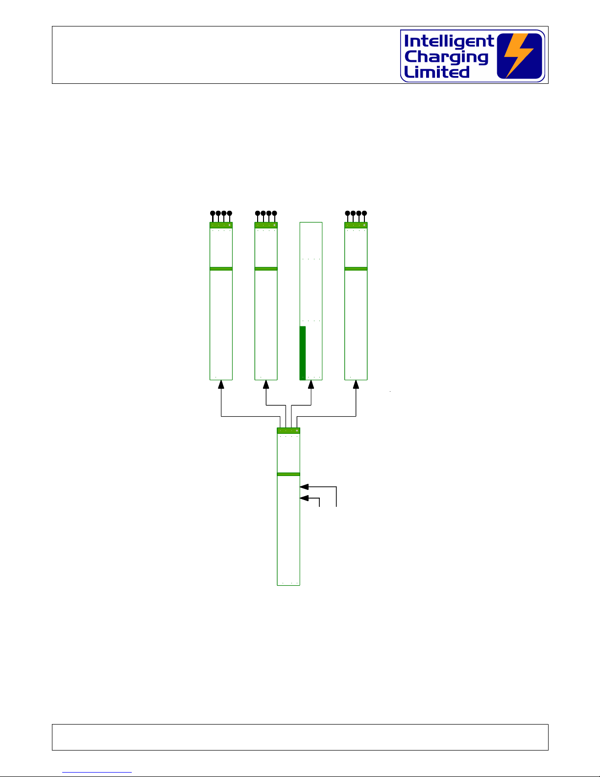
The cell monitor is supplied as an interface unit with 21 patch lead connection for
connecting to batteries via individual clamps. It has a connector fitted to it where
“crown” assembly can be plugged in. The “crown” arrangement is placed onto the top
of the battery with contact to the cells made via stainless test pins. The “crown”
arrangement is manufactured to suite one style of battery. If many different styles of
batteries are in use a “crown” will be required for each battery.
3.2 Charging With The Cell Monitor
3.2.1 Constant current charge.
In the constant current charge mode using the cell monitor interface the charge will
take place at the predefined constant current until all the cells have reached the target
set point typically 1.55V. At which time the charge rate will change to the additional
time rate and the charge will continue until the additional time has elapsed. If at any
time during the charge any cell voltage exceeds the cell overcharge voltage typically
1.65V the charge will stop. If a printer is connected to the unit the cell voltages can be
Doc: DWG1060-12-R3 IC48V Operators manual.odt Page 12 of 58 Copyright Material of Intelligent Charging Limited © 2015
Printed On : 14/06/17

IC48V Battery Charger/Analyser
Operator Manual
printed at predefined timed intervals or can be printed by simply pressing the ‘.’ key. If
a printed report is required at the end of the charge, the final cell voltages will be
included.
3.3 Discharging With The Cell Monitor
3.3.1 Capacity Testing To Target Or Time
This capacity test mode allows you to discharge the battery at the required current for
your pre-selected time until one cell goes below a predefined target voltage typically
1.00V at which point the discharge stops and the battery capacity can be seen. If a
printer is connected to the unit the cell voltages can be printed at predefined timed
intervals or can be printed by simply pressing the ‘.’ key. If a printed report is required
at the end of the capacity test the final cell voltages will be included.
3.3.2 Automatic Cell Balance
This mode allows you to set a predefined discharge current to flatten the battery and to
perform an automatic cell balancing exercise. While during the discharge any cell
approaches 0.00V its balancing resistor will be switched in to reduce the reverse charge
effect. When the battery voltage falls below 3.0V and the discharge current falls below
2.0A the cell-monitoring interface will automatically switch in all the balancing resistors
and will remain it that state until either the CLR key is pressed or the Discharge Time
elapses.
3.4 Monitor Only Mode
A mode of operation is available where the cell monitor interface can be scanned while
the unit is idle. This is obtained through the SYSTEM menu. While in this mode the ‘B’
& ‘C’ keys will display the textual cell voltages or the bar graph respectively. While this
mode is active and the printer is installed a snapshot of the cell voltages can be printed
by pressing the ‘.’ key. When accessing the monitor mode the option of applying the
cell balancing resistors is available, so manual cell balancing can be applied.
3.5 Normal Charge or Capacity Test Mode
When activating the normal charge and capacity test modes if the unit detects that the
cell monitor is connected it will ask the operator if cell monitoring is required during the
operation. If this is selected the cell monitor will scan the cells and report the voltages
but will take no actions on individual cell voltages etc.
3.6 Cell Monitor Extended Display Reference
When performing a charge or capacity test the display will always default to showing
the main process conditions, but when the cell monitor is in use there are two
additional displays which give the operator a list of cell voltages at the instant in time or
a graphical bar display of the cell voltages. The alternative displays are viewed by
pressing either of the ‘A’, ‘B’ or ‘C’ keys on the keypad.
Doc: DWG1060-12-R3 IC48V Operators manual.odt Page 13 of 58 Copyright Material of Intelligent Charging Limited © 2015
Printed On : 14/06/17

IC48V Battery Charger/Analyser
Operator Manual
The ‘A’ key changes the display to the main process conditions as shown:
The ‘B’ key changes the display to the full 20-cell voltage list as shown:
The ‘C’ key changes the display to a bar graph of cell voltages as shown:
While the graphical display is viewed the range of the display can be dynamically
changed from the default 0.8 to 1.8V to a bottom limit of 0.0V to 1.0V or an upper limit
of 1.0 to 2.0V by pressing and holding the "0" key and pressing the "" or ""
respectively. Each step is an increment or decrement of 0.1V.
3.7 Printing Data When Using The Cell Monitor
If the printer is fitted to the charger analyser and the cell monitor is in use there are
additional printing facilities available. When performing a charge or capacity test the cell
voltages can be printed manually at a time to suit you by simply pressing the ‘.’ key or
a print interval can be specified in minutes. When the cell monitor is in use the full list
of cell voltages will also be included in the final print at the end of the operation. The
cell monitor printout is a similar format to the figure below:
Doc: DWG1060-12-R3 IC48V Operators manual.odt Page 14 of 58 Copyright Material of Intelligent Charging Limited © 2015
Printed On : 14/06/17
STOP
*
CLR
1.. 5 1.35V 1.35V 1.35V 1.35V 1.35V
6..10 1.35V 1.35V 1.35V 1.35V 1.35V
11..15 1.35V 1.35V 1.35V 1.35V 1.35V
16..20 1.35V 1.35V 1.35V 1.35V 1.35V
STOP
*
CLR
1.80
1.20
0.08
26.9V 0.0A
HIGH = 1.36V
LOW = 1.32V
C 01 = 1.32V
T1.55V 1.0A + 1.0A 1.0H O1.65V F 5.0H
27.6V 0.5A 0h00m00
MANUAL 24.0V CELL MONITOR CC CHARGE
STOP
*
CLR

IC48V Battery Charger/Analyser
Operator Manual
3.8 Cell Number Reversal
The cell monitor accessory is marked with cell numbers starting with #1 through to #20
(The maximum number of calls that can be monitored). Cell #1 is considered to be the
cell which is connected to the negative (-ve) cell end of the battery whereas cell #20
(in a 20 cell battery) is considered to be the cell which is connected to the positive
(+ve) end of the battery.
Many battery manufacturers use the reverse cell numbering where cell #1 is the
positive (+ve) end of the battery and in the case of a 20 cell battery the #20 cell is the
negative.
Because of this numbering technique the battery charger has an option in the cell,
monitor settings to “reverse” the cell numbering for display and printing purposes. The
cell displays show which is +ve end of the battery and which is the negative so that if
the cell numbering is reversed it is shown which way round the numbering takes.
3.9 Cell Monitor Specifications
Power +5.0V
Cell Voltage Range -2.5V to +2.5V
Max No. Cells 20
Full Scan Rate 5 seconds
Balance Switching current 2.0A
Balance continuous current 1.0A
Balance Resistance 1.0Ω ±1% 2W
Doc: DWG1060-12-R3 IC48V Operators manual.odt Page 15 of 58 Copyright Material of Intelligent Charging Limited © 2015
Printed On : 14/06/17
-----------------------CELL VOLTAGES AT 1.5H
01 1.46V 02 1.46V
03 1.46V 04 1.46V
05 1.46V 06 1.46V
07 1.46V 08 1.46V
09 1.46V 10 1.45V Lo
11 1.46V Hi 12 1.46V
13 1.46V 14 1.46V
15 1.46V 16 1.46V
17 1.46V 18 1.46V
19 1.46V 20 1.46V
------------------------
IC48V Battery Charger/Analyser
Operator Manual
4 Equipment Menu Operation
The Battery Charger Analyser is operated by the use of a simple menu structure which is
accessed by simply pressing the A, B, C or ‘.’ keys. To get back to the main menu the CLR
key is pressed repeatedly. The following flowcharts illustrate the menu structure.
4.1 Main Menu
Doc: DWG1060-12-R3 IC48V Operators manual.odt Page 16 of 58 Copyright Material of Intelligent Charging Limited © 2015
Printed On : 14/06/17
THE MAIN MENU
SETTINGS MENU
PRINT
SET CLOCK
SYSTEM
DISPLAY
ABC
DISCHARGE MENU
PREVIOUS
LIBRARY
MANUAL
PROCESS
ABC
CHARGE MENU
PREVIOUS
LIBRARY
MANUAL
PROCESS
ABC
26 Feb 2009 10:16 o CM TP
MB73P+ Bat 26.9V
** SERVICEABLE ** LIBRARY
CHARGE
DISCHARGE
SETTINGS
ABC
NO DATA
Move
CLR-Abort
ENT-Select
1 NO DATA 2 NO DATA
5 NO DATA
7 NO DATA 8 NO DATA
6 NO DATA
3 NO DATA 4 NO DATA
CM SHOWN WHEN CELL MONITOR IS CONNECTED
TP IS SHOWN WHEN TEMPERATURE PROBE IS CONNECTED

IC48V Battery Charger/Analyser
Operator Manual
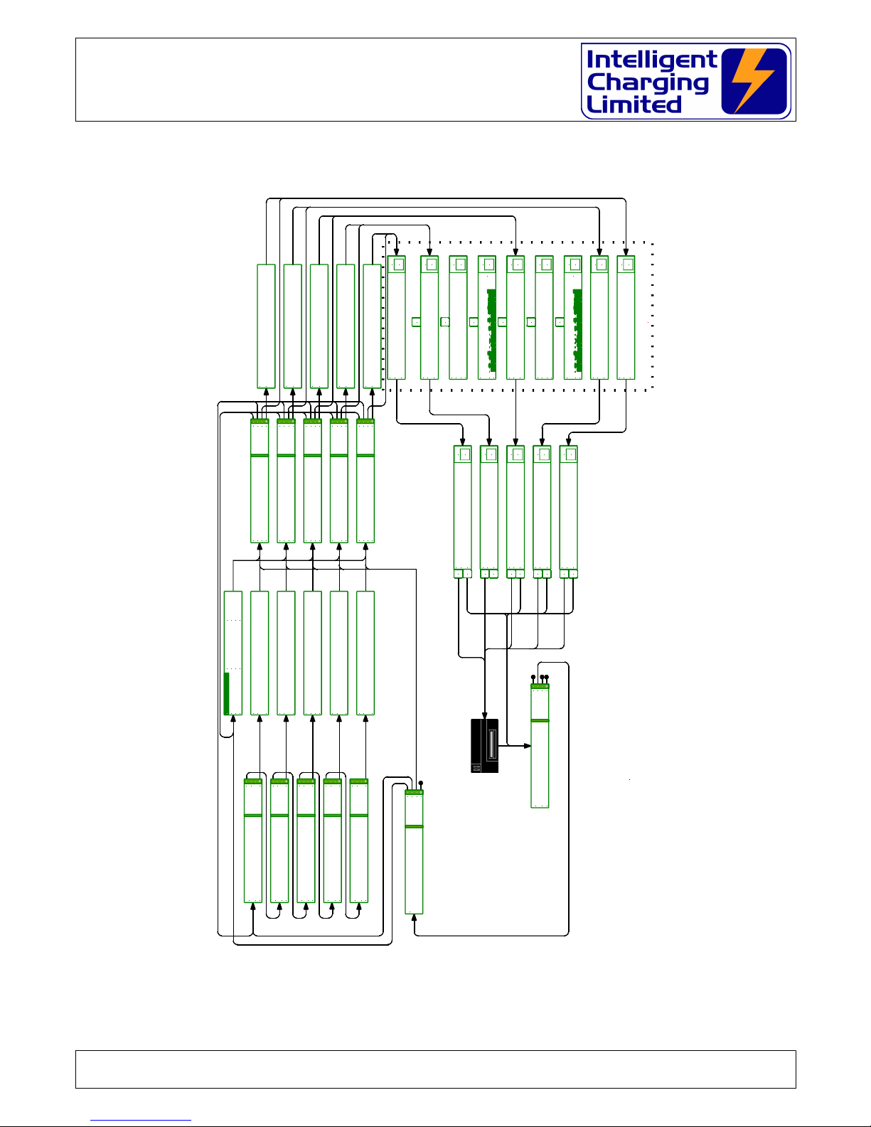
4.2 Charging Menu
Doc: DWG1060-12-R3 IC48V Operators manual.odt Page 17 of 58 Copyright Material of Intelligent Charging Limited © 2015
Printed On : 14/06/17
CHARGING IN PROGRESS
CHARGING OPERATIONS
A
ENT
CLR
ENT
CLR
ENT
CLR
ENT
CLR
C16..C20 1.35V 1.35V 1.35V 1.35V 1.35V
STOP
*
CLR
C 1..C 5 1.35V 1.35V 1.35V 1.35V 1.35V
C 6..C10 1.35V 1.35V 1.35V 1.35V 1.35V
C11..C15 1.35V 1.35V 1.35V 1.35V 1.35V
STOP
*
CLR
1.80
1.20
0.08
26.9V 0.0A
HIGH = 1.36V
LOW = 1.32V
C 01 = 1.32V
USE A/B TO CHARGE MODE
CHARGE MODE
CONSTANT VOLTAGE CHARGE
>> NEXT >>
<< PREV <<
ACCEPT
ABC
C
CHARGE MENU
PREVIOUS
LIBRARY
MANUAL
PROCESS
ABC
CHARGE MODE
CELL MONITOR CC CHARGE
>> NEXT >>
<< PREV <<
ACCEPT
ABC
USE A/B TO CHARGE MODE
CHARGE MODE
CONSTANT CURRENT CHARGE
>> NEXT >>
<< PREV <<
ACCEPT
ABC
USE A/B TO CHARGE MODE
USE A/B TO CHARGE MODE
CHARGE MODE
MULTI-STEP CHARGE
>> NEXT >>
<< PREV <<
ACCEPT
ABC
26 Feb 2009 10:16 o CM TP
MB73P+ Bat 26.9V
** SERVICEABLE ** LIBRARY
CHARGE
DISCHARGE
SETTINGS
ABC
NO DATA
éèêç Move
CLR-Abort
ENT-Select
1 NO DATA 2 NO DATA
5 NO DATA
7 NO DATA 8 NO DATA
6 NO DATA
3 NO DATA 4 NO DATA
Nominal Volts 12.0V Target Volts 13.8V
Min 0.0A Rise 0.0A Target Fail 5.0H
HELP LINE APPEARS HERE
Charge Amps 1.0A Charge Time 1.0H
TgFail 24.0H Ochg 1.65V CP 0m
Extra T 1.0H Extra Amps 0.5A
LIBRARY
MANUAL
TIMED
ABC
Target 1.55V Max Amps 1.0A
CELL MONITOR CC CHARGE 12.0V
STARTExtra Amps 0.5A For 1.0H Targ Fail 24.0H
Number If Cells 20 Cell Target Volts 1.55V
HELP LINE APPEARS HERE
Charge Amps 1.0A Overcharge Volts 1.65V
Cell Print 0H
Extra Amps 0.5A For 1.0H Targ Fail 24.0H
Nominal Volts 12.0V Target Volts 13.8V
HELP LINE APPEARS HERE
Charge Amps 1.0A Overcharge Volts 15.0V
TgFail 24.0H Overcharge 15.0V
Extra T 1.0H Extra Amps 0.5A
LIBRARY
MANUAL
TIMED
ABC
Target 13.8V Max Amps 1.0A
CONSTANT CURRENT CHARGE 12.0V
START
Overcharge Volts 15.0V
3: 1.0A 1.0H 4: 1.0A 1.0H
LIBRARY
MANUAL
TIMED
ABC
1: 1.0A 1.0H 2: 1.0A 1.0H
MULTI-STEP CHARGE 12.0V
START
Fail Tm 0.0H Amps Rise 0.0A
Run Tm 1.0H Min Amps 0.0A
LIBRARY
MANUAL
TIMED
ABC
Target 13.8V Max Amps 1.0A
CONSTANT VOLTAGE CHARGE 12.0V
START
T1.55V 1.0A + 1.0A 1.0H O1.65V F 5.0H
27.6V 0.5A 0h00m00
MANUAL 24.0V CELL MONITOR CC CHARGE
STOP
*
CLR
MANUAL 24.0V MULTI-STEP CHARGE
27.6V 0.5A 0h00m00
Step #1 1.0A For 1.0H Overchrg 13.2V
STOP
*
CLR
27.6V 0.5A 0h00m00
MANUAL 24.0V CONSTANT CURRENT CHARGE
T13.8V 1.0A + 1.0A 1.0H O13.2V F 5.0H
STOP
*
CLR
27.6V 0.5A 0h00m00
MANUAL 24.0V CONSTANT VOLTAGE CHARGE
T 13.8V 1.0A 1.0H M0.0A R0.0AF 5.0H
STOP
*
CLR
PRNT
#
ENT
27.6V 0.5A 0h00m00
MANUAL 24.0V STOPPED BY OPERATOR
T1.55V 1.0A + 1.0A 1.0H O1.65V F 5.0H
PRNT
#
ENT
MANUAL 24.0V STOPPED BY OPERATOR
27.6V 0.5A 0h00m00
Step #1 1.0A For 1.0H Overchrg 13.2V
PRNT
#
ENT
27.6V 0.5A 0h00m00
MANUAL 24.0V STOPPED BY OPERATOR
T13.8V 1.0A + 1.0A 1.0H O13.2V F 5.0H
PRNT
#
ENT
27.6V 0.5A 0h00m00
MANUAL 24.0V STOPPED BY OPERATOR
T 13.8V 1.0A 1.0H M0.0A R0.0AF 5.0H
Overcharge Volts 15.0V
Nominal Volts 12.0V Charge Step #4
HELP LINE APPEARS HERE
Charge Amps 1.0A Charge Time 1.0H
B
Delay Before CM CC CHARGE : 0.0H
Enter Delayed Start In Hours
Delay Before MS CHARGE : 0.0H
Enter Delayed Start In Hours
Delay Before CC CHARGE : 0.0H
Enter Delayed Start In Hours
Delay Before CV CHARGE : 0.0H
Enter Delayed Start In Hours
IC48V Battery Charger/Analyser
Operator Manual
4.3 Capacity Testing Menu
Doc: DWG1060-12-R3 IC48V Operators manual.odt Page 18 of 58 Copyright Material of Intelligent Charging Limited © 2015
Printed On : 14/06/17
CAPACITY TEST IN PROGRESS
CAPACITY TESTING OPERATIONS
A
B
C
27.6V 0.5A 0h 0m 0
MANUAL 24.0V FULL DISCHARGE
Alarm 3.0V Amp 1.0A Tim 1.0H > 0.98H
STOP
*
CLR
27.6V 0.5A 0h 0m 0
MANUAL 24.0V AUTOMATIC CELL BALANCE
Balanced 0 Amp 1.0A Tim 1.0H > 0.98H
STOP
*
CLR
27.6V 0.5A 0h 0m 0
MANUAL 24.0V CAPACITY TEST CELL MON
Targ 1.00V Amp 1.0A Tim 1.0H > 0.98H
STOP
*
CLR
27.6V 0.5A 0h 0m 0
MANUAL 24.0V CAPACITY TEST TO 100%
Targ 1.0V Amp 1.0A Tim 1.0H > 0.98H
STOP
*
CLR
27.6V 0.5A 0h 0m 0
MANUAL 24.0V CAPACITY TEST TO TARGET
Targ 1.0V Amp 1.0A Tim 1.0H > 0.98H
STOP
*
CLR
A
B
C
ENT
CLR
ENT
CLR
ENT
CLR
ENT
CLR
ENT
CLR
DISCHARGE MODE
FULL DISCHARGE
>> NEXT >>
<< PREV <<
ACCEPT
ABC
USE A/B TO CHARGE MODE
27.6V 0.5A 0h 0m 0
MANUAL 24.0V CAPACITY TEST TO 100%
Targ 1.0V Amp 1.0A Tim 1.0H > 0.98H
STOP
*
CLR
27.6V 0.5A 0h 0m 0
MANUAL 24.0V CAPACITY TEST TO TARGET
Targ 1.0V Amp 1.0A Tim 1.0H > 0.98H
STOP
*
CLR
STOP
*
CLR
1.80
1.20
0.08
26.9V 0.0A
HIGH = 1.36V
LOW = 1.32V
C 01 = 1.32V
STOP
*
CLR
1.. 5 1.35V 1.35V 1.35V 1.35V 1.35V
6..10 1.35V 1.35V 1.35V 1.35V 1.35V
11..15 1.35V 1.35V 1.35V 1.35V 1.35V
16..20 1.35V 1.35V 1.35V 1.35V 1.35V
27.6V 0.5A 0h 0m 0
MANUAL 24.0V CAPACITY TEST CELL MON
Targ 1.00V Amp 1.0A Tim 1.0H > 0.98H
STOP
*
CLR
STOP
*
CLR
1.80
1.20
0.08
26.9V 0.0A
HIGH = 1.36V
LOW = 1.32V
C 01 = 1.32V
STOP
*
CLR
1.. 5 1.35V 1.35V 1.35V 1.35V 1.35V
6..10 1.35V 1.35V 1.35V 1.35V 1.35V
11..15 1.35V 1.35V 1.35V 1.35V 1.35V
16..20 1.35V 1.35V 1.35V 1.35V 1.35V
27.6V 0.5A 0h 0m 0
MANUAL 24.0V AUTOMATIC CELL BALANCE
Balanced 0 Amp 1.0A Tim 1.0H > 0.98H
STOP
*
CLR
27.6V 0.5A 0h 0m 0
MANUAL 24.0V FULL DISCHARGE
Alarm 3.0V Amp 1.0A Tim 1.0H > 0.98H
STOP
*
CLR
Delay Before FULL DISCHRG : 0.0H
Enter Delayed Start In Hours
Delay Before CELL BALANCE : 0.0H
Enter Delayed Start In Hours
Delay Before CELL CAPTEST : 0.0H
Enter Delayed Start In Hours
Delay Before CAPTEST TARG : 0.0H
Enter Delayed Start In Hours
Delay Before CAPTEST 100% : 0.0H
Enter Delayed Start In Hours
Discharge Time 1.0H
Discharge Amps 1.0A
LIBRARY
MANUAL
TIMED
ABC
Alarm Volts 3.0V
FULL DISCHARGE 24.0V
START
LIBRARY
MANUAL
TIMED
ABC
AUTOMATIC CELL BALANCE 12.0V
START
Discharge Time 1.0H
Discharge Amps 1.0A
LIBRARY
MANUAL
TIMED
ABC
Cell Target Volts 1.00V
CAPACITY TEST CELL MON 12.0V
START
Discharge Time 1.0H CP 0M
Discharge Amps 1.0A
LIBRARY
MANUAL
TIMED
ABC
Target Volts 10.0V
CAPACITY TEST TO TARGET 12.0V
START
Discharge Time 1.0H
Discharge Amps 1.0A
LIBRARY
MANUAL
TIMED
ABC
Target Volts 10.0V
CAPACITY TEST TO 100% 12.0V
START
Discharge Time 1.0H
Discharge Amps 1.0A
Nominal Volts 12.0V Alarm Volts 3.0V
HELP LINE APPEARS HERE
Discharge Amps 1.0A Test Time 1.0H
HELP LINE APPEARS HERE
Number Of Cells 20
Discharge Amps 1.0A Test Time 1.0H
Number Of Cells 20 Cell Target Volts 1.00V
HELP LINE APPEARS HERE
Cell Print Interval 0M
Discharge Amps 1.0A Test Time 1.0H
Nominal Volts 12.0V Target Volts 10.0V
HELP LINE APPEARS HERE
Discharge Amps 1.0A Test Time 1.0H
HELP LINE APPEARS HERE
Nominal Volts 12.0V Target Volts 10.0V
Discharge Amps 1.0A Test Time 1.0H
NO DATA
éèêç Move
CLR-Abort
ENT-Select
1 NO DATA 2 NO DATA
5 NO DATA
7 NO DATA 8 NO DATA
6 NO DATA
3 NO DATA 4 NO DATA
DISCHARGE MENU
PREVIOUS
LIBRARY
MANUAL
PROCESS
ABC
DISCHARGE MODE
AUTOMATIC CELL BALANCE
>> NEXT >>
<< PREV <<
ACCEPT
ABC
USE A/B TO CHARGE MODE
DISCHARGE MODE
CAPACITY TEST CELL MON
>> NEXT >>
<< PREV <<
ACCEPT
ABC
USE A/B TO CHARGE MODE
26 Feb 2009 10:16 o CM TP
MB73P+ Bat 26.9V
** SERVICEABLE ** LIBRARY
CHARGE
DISCHARGE
SETTINGS
ABC
DISCHARGE MODE
CAPACITY TEST TO 100%
>> NEXT >>
<< PREV <<
ACCEPT
ABC
USE A/B TO CHARGE MODE
DISCHARGE MODE
CAPACITY TEST TO TARGET
>> NEXT >>
<< PREV <<
ACCEPT
ABC
USE A/B TO CHARGE MODE
 Loading...