

TS25 MKII : TS25-BAS1-KIT : TS25-BAS1-CAN-240
Battery charger/analyser : Operators Manual
Doc: DWG1044-09-R16 TS25 MKII Operators manual.odt Page 1 of 46 Copyright Material of Intelligent Charging Limited © 2015
Printed On : 12/06/17
DANGER
Disconnect the
mains supply before
removing this cover
MEM
Bxx
ON
OFFIO
MEM
Bxx
ON
OFFIO
MEM
Bxx
ON
OFFIO
MEM
Bxx
ON
OFFIO
VOLTS TIME
AMPS
TEST
END ONE
VOLTSTIME
AMPS
TEST
END
%
%
ALARM
POWER SWITCH
POWER SWITCHPOWER SWITCH
POWER SWITCH
KEEP AIRFLOW C LEAR
KEEP AIRFLOW C LEARKEEP AIRFLOW C LEAR
KEEP AIRFLOW C LEAR
10cm
10cm10cm
10cm
KEEP AIRFLOW CLEAR
KEEP AIRFLOW CLEARKEEP AIRFLOW CLEAR
KEEP AIRFLOW CLEAR
10cm
10cm10cm
10cm
EXTD
ENTR
DISP DATA
A SET PROC
V SETCHRG BATT
TEST ONE T SET
START
STOP MUTE
EXTD
ENTR
DISP DATA
A SET PROC
V SETCHRG BATT
TEST T SET
START
STOP
TS25 MKII
TS25-BAS1-KIT
TS25-BAS1-CAN-240
Battery Charger/Analyser
Operators Manual

TS25 MKII : TS25-BAS1-KIT : TS25-BAS1-CAN-240
Battery charger/analyser : Operators Manual
TABLE OF CONTENTS
1 MANUAL REVISION HISTORY 4
2 TS25 MKII DESCRIPTION 5
3 CONTROLS AND INDICATORS 7
3.1 DISPLAY 8
3.2 POWER SWITCH 9
3.3 AUDIBLE ALARM 9
3.4 CHARGE & CAPACITY TEST CIRCUIT BREAKERS 9
3.5 BATTERY CONNECTORS 9
3.6 KEYBOARD 10
4 USING THE TS25 MKII 11
4.1 CONNECTING BATTERIES 11
4.2 CAPACITY TESTING BATTERIES 14
4.3 CHARGING BATTERIES 17
4.4 ENTERING BATTERY DATA 20
4.5 USING THE ONE MODE OF OPERATION 22
4.6 RESETTING THE TS25 MKII 22
4.7 DISPLAY MNEMONICS 24
4.8 ERROR CODES 25
5 CALIBRATION 27
5.1 EQUIPMENT REQUIRED 27
5.2 PERFORMANCE CHECKING 27
5.3 RE-CALIBRATION 28
5.4 CALIBRATION PROBLEMS 29
5.5 CALIBRATION EQUIPMENT CONNECTIONS 30
6 ROUTINE MAINTENANCE 31
Doc: DWG1044-09-R16 TS25 MKII Operators manual.odt Page 2 of 46 Copyright Material of Intelligent Charging Limited © 2015
Printed On : 12/06/17

TS25 MKII : TS25-BAS1-KIT : TS25-BAS1-CAN-240
Battery charger/analyser : Operators Manual
6.1 INTERNAL BATTERY REPLACEMENT 31
7 BATTERY LIBRARY 32
7.1 RETRIEVING A LIBRARY ITEM 32
7.2 ENTERING OR MODIFYING A LIBRARY ENTRY 32
8 DEFAULT BATTERY LIBRARY 33
9 SPECIFICATIONS 43
10 PRODUCT DISPOSAL INSTRUCTIONS 44
11 PRODUCT WARRANTY 45
Doc: DWG1044-09-R16 TS25 MKII Operators manual.odt Page 3 of 46 Copyright Material of Intelligent Charging Limited © 2015
Printed On : 12/06/17

TS25 MKII : TS25-BAS1-KIT : TS25-BAS1-CAN-240
Battery charger/analyser : Operators Manual
1 Manual Revision History
Rev Date Description
0 08-03-2007 FIRST WRITTEN
1 01-11-2007 Detail Changes
2 26-02-2008 Added calibration procedures and maintenance.
3 05-03-2008 Added battery connection diagrams
4 11-03-2008 Added Controls & Indicators Section
5 11-05-2008 Added Enersys batteries 9750D0740 & 0744 to library. More error fault codes
added.
6 13-06-2008 Added new error code where if current fails to be driven then warning 14 occurs.
7 19-06-2008 Added text about warning 15 for detection of battery voltage greater than target
while constant voltage charging.
8 25-06-2008 Changed library entry 61 to correct part No.
9 02-07-2008 Added comment on suitability of capacity test parameters for Enersys 9750-0744
Battery
10 12-08-2008 Corrected position of CHRG & TEST on keypad legend.
11 26-01-2009 Added Enersys 9750D0730 to built in library
12 30-09-2014 Corrected annotation on keypad diagram CHRG and TEST reversed.
13 21-11-2014 Reworded the data entry paragraphs in section 4.4 to make clearer.
14 20-01-2015 Graphic images of TS25 amended as they show CHRG & TEST reversed.
15 21-07-2015 Formatting changes.
16 23-09-2015 Corrected use of “efficiency” where should read “capacity”. Corrected resolution for
capacity test time.
Doc: DWG1044-09-R16 TS25 MKII Operators manual.odt Page 4 of 46 Copyright Material of Intelligent Charging Limited © 2015
Printed On : 12/06/17

TS25 MKII : TS25-BAS1-KIT : TS25-BAS1-CAN-240
Battery charger/analyser : Operators Manual
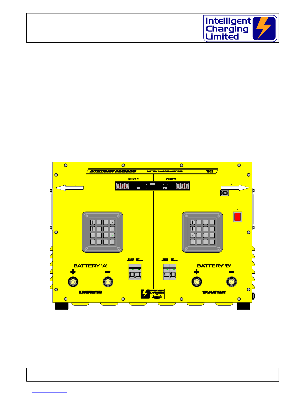
2 TS25 MKII DESCRIPTION
The TS25 MKII Dual Channel Battery Charger / Analyser is an electronically controlled
combined universal battery charging unit with built in battery analysing capabilities. It is
housed in a heavy-duty metal enclosure designed to free stand on a workbench. As it is
supplied it is configured for use from a standard 240V 50/60Hz supply.
Equipment control is via an interactive numeric display and led state indicators. Data entry is
via two 16-key keypads. Each channel displayed data and data entry is independent of the
status of the other channel. So new processes can be set up even when the other channel is
in the middle of a charge or capacity test.
Battery data is stored internally in the unit in battery-backed memory. A list of commonly
used batteries is included along with the accepted charging and testing data. The operator
can extend or modify this list by entering the details of the battery to be included on the
display and keyboard. The battery library data can be restored to the defaults by a special
key sequence permitted via the keyboard.
Batteries are connected to the front of the unit by means of two individual heavy duty
connectors. Connection to the battery has to be made via the appropriate connectors for
that battery. Contact Intelligent-Charging for special lead sets made to order.
The TS25 MKII has extended operating capabilities compared to its predecessor the TS25.
Maximum charge current has been increased to 12A per channel, and capacity testing still
remains at 25A per channel.
The TS25 MKII still has paralleling mode where using a common paired cable both channels
can be run in parallel to provide a charge capability of 24A and a capacity test capability of
50A.
There are two capacity test programs built into the unit and these can be selected via the
configuration menu and capacity testing can be performed such that it will stop testing when
a battery reached 100% or less, or alternately can carry on capacity testing until the battery
reached the set termination threshold and thus reporting the actual battery capacity greater
than 100%.
There are three charging modes built into the unit, for Lead Acid (Pb) constant voltage
charging can be performed for a fixed period of time and for Nickel Cadmium (NiCd)
constant current charging can be performed with termination on time and over voltage
parameters, and also for Nickel Cadmium batteries a new charge mode which allows a
constant current charge to be performed up until a voltage set point, where the charge will
then continue charging until the additional time specified has passed.
Doc: DWG1044-09-R16 TS25 MKII Operators manual.odt Page 5 of 46 Copyright Material of Intelligent Charging Limited © 2015
Printed On : 12/06/17

TS25 MKII : TS25-BAS1-KIT : TS25-BAS1-CAN-240
Battery charger/analyser : Operators Manual
The TS25 MKII contains the ability that will allow it to be calibrated by the end user. The
equipment needed is a good 24V battery, an ammeter capable of reading up to 25A (or a
shunt and milli-voltmeter combination) and a voltmeter capable of reading up to 30V. The
re-calibration process only takes a few minutes and this is done without the need to access
the interior of the TS25 MKII.
The TS25 MKII no longer supports deep discharge recovery mode. It is thought that if a
battery requires this level of charge to "recover" it then the battery is not fit for use anyway
and should be disposed of for re-cycling.
The TS25 MKII contains two hi flow rate fans to extract the heat energy generated internally
when running in capacity test mode.
Doc: DWG1044-09-R16 TS25 MKII Operators manual.odt Page 6 of 46 Copyright Material of Intelligent Charging Limited © 2015
Printed On : 12/06/17
TS25 MKII : TS25-BAS1-KIT : TS25-BAS1-CAN-240
Battery charger/analyser : Operators Manual
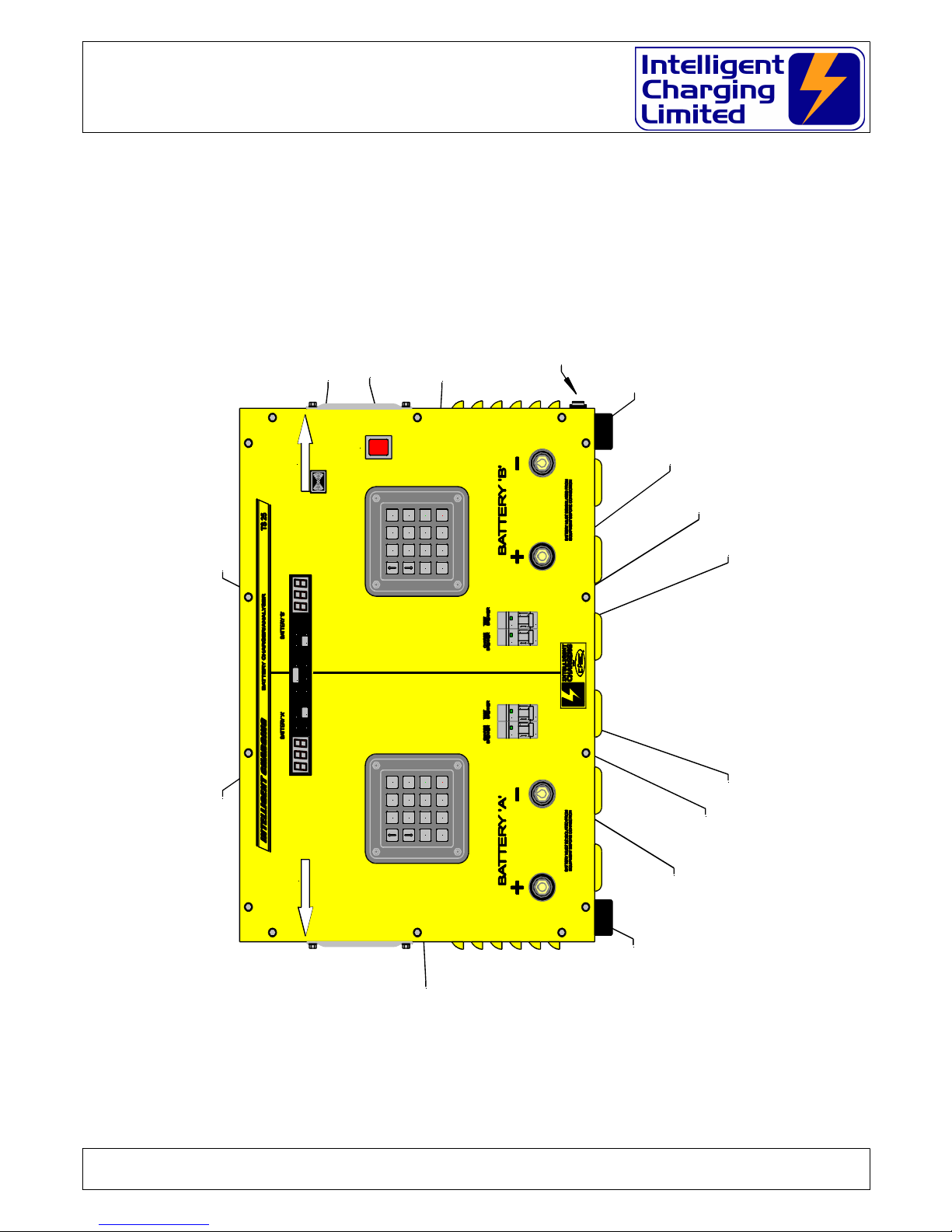
3 CONTROLS AND INDICATORS
Doc: DWG1044-09-R16 TS25 MKII Operators manual.odt Page 7 of 46 Copyright Material of Intelligent Charging Limited © 2015
Printed On : 12/06/17
A CHANNEL DISPLAY B CHANNEL DISPLAY
AUDIBLE ALARM
POWER SWITCH
AC POWER FUSE & INLET
B CHANNEL DATA
ENTRY KEYPAD
A CHANNEL DATA
ENTRY KEYPAD
CHANNEL A POSITIVE
BATTERY LEAD CONNECTOR
CHANNEL A NEGATIVE
BATTERY LEAD CONNECTOR
CHANNEL B NEGATIVE
BATTERY LEAD CONNECTOR
CHANNEL B POSITIVE
BATTERY LEAD CONNECTOR
CHANNEL A CHARGE SAFETY BREAKER
CHANNEL A CAPACITY TEST SAFETY CIRCUIT BREAKER
CHANNEL B CAPACITY TEST SAFETY CIRCUIT BREAKER
CHANNEL A CHARGE SAFETY CIRCUIT BREAKER
DANGER
Disconnect the
mains supply before
removing this cover
MEM
Bxx
ON
OFF
I
O
MEM
Bxx
ON
OFF
I
O
MEM
Bxx
ON
OFF
I
O
MEM
Bxx
ON
OFF
I
O
VOLTS TIME
AMPS
TEST
END ONE
VOLTSTIME
AMPS
TEST
END
%
%
ALARM
POWER SWITCH
POWER SWITCH
POWER SWITCH
POWER SWITCH
KEEP AIRFLOW CLEAR
KEEP AIRFLOW CLEAR
KEEP AIRFLOW CLEAR
KEEP AIRFLOW CLEAR
10cm
10cm
10cm
10cm
KEEP AIRFLOW CLEAR
KEEP AIRFLOW CLEAR
KEEP AIRFLOW CLEAR
KEEP AIRFLOW CLEAR
10cm
10cm
10cm
10cm
EXTD
ENTR
DISP DATA
A SET PROC
V SETCHRG BATT
TEST ONE T SET
START
STOP MUTE
EXTD
ENTR
DISP DATA
A SET PROC
V SETCHRG BATT
TEST T SET
START
STOP
TS25 MKII : TS25-BAS1-KIT : TS25-BAS1-CAN-240
Battery charger/analyser : Operators Manual
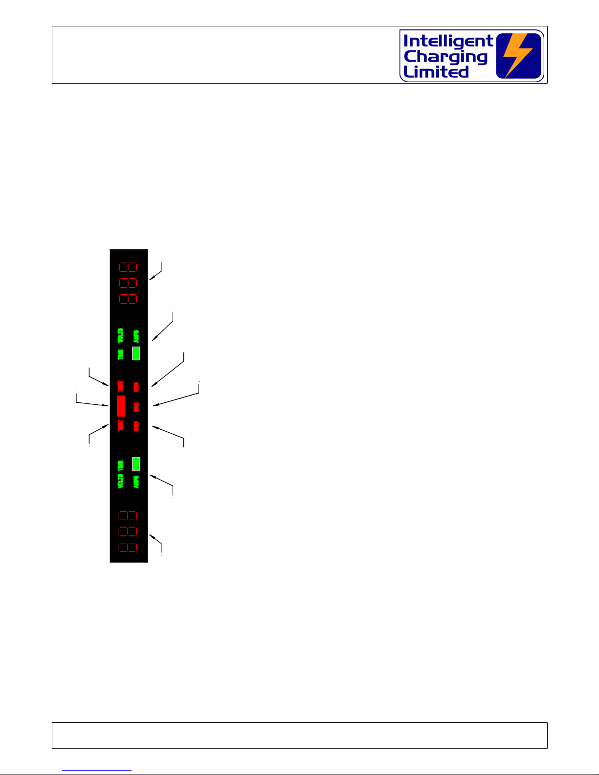
3.1 DISPLAY
• NUMERIC DISPLAY
o Voltage is displayed in volts to a resolution of 0.1V
o Current is displayed in Amperes to a resolution of
0.1A
o Capacity test time is displayed in minutes to a
resolution of 1 minute.
o Charge time is displayed in Hours to a resolution of
0.1H (One tenth). Capacity test time is displayed in
Minutes to a resolution of 1 Minute.
o Battery capacity is displayed in percent to a
resolution of 1%.
• NUMERIC DISPLAY INDICATORS
o VOLTS illuminated means voltage is being displayed
or entered.
o AMPS illuminated means current is being displayed
or entered.
o TIME illuminated means time is being displayed or
entered.
o % Illuminated means that battery capacity is being
displayed.
o TEST illuminated means that the unit is set to
capacity test mode otherwise it is set to charge
mode.
o END illuminated means that the unit is stopped.
o ALARM illuminated means that the unit has just
stopped and the alarm has sounded.
o ONE illuminated means that ONE mode has been
selected and the paralleling leads must be used.
Doc: DWG1044-09-R16 TS25 MKII Operators manual.odt Page 8 of 46 Copyright Material of Intelligent Charging Limited © 2015
Printed On : 12/06/17
%
%
ALARM
CHANNEL A NUMERIC DISPLAY CHANNLE B NUMERIC DISPLAY
CHANNEL A NUMERIC DISPLAY MODE INDICATOR CHANNEL B NUMERIC DISPLAY MODE INDICATOR
ILLUMINATED IF CAPTEST SELECTED ILLUMINATED IF CHANNEL B CAPTEST MODE IS SELECTED
ILLUMINATED IF THE CHARGER ALARM HAS SOUNDED
ILLUMINATED IF CHANNEL A IS STOPPED ILLUMINATED IF CHANNEL B IS STOPPED
ILLUMINATED IF THE "ONE" MODE OF OPERATION IS SELECTED

TS25 MKII : TS25-BAS1-KIT : TS25-BAS1-CAN-240
Battery charger/analyser : Operators Manual
3.2 POWER SWITCH
Operation of this switch will either apply or remove the ac inlet power from the TS25
MKII
WARNING
AVOID REMOVING THE POWER FROM THE UNIT WHILE THE UNIT IS
PERFORMING A CAPACITY TEST OR CHARGE.
3.3 AUDIBLE ALARM
When a charge or capacity test has completed or stopped in error the audible alarm
will sound until the MUTE or STOP key is pressed.
3.4 CHARGE & CAPACITY TEST CIRCUIT BREAKERS
The circuit breakers are fitted to prevent high currents from being driven into the
battery or into the unit should a fault condition occur. Always ensure that the circuit
breaker is in the ON position before starting a charge or capacity test.
WARNING
NEVER SWITCH THE CIRCUIT BREAK TO ON WHEN THE UNIT IS PERFORMING
A CHARGE OR CAPACITY TEST AS SEVERE DAMAGE MAY OCCUR TO THE
BATTERY OR THE TS25 MKII
ALWAYS PRESS STOP FIRST
If the circuit breaker operates during a charge immediately press STOP on BOTH
charger channels and remove power from the unit and disconnect the battery.
Operation of the circuit breaker is an indication of a fault and the unit will need to be
checked before use.
3.5 BATTERY CONNECTORS
The battery terminal are where the supplied leads are connected to the TS25 MKII. It
is recommended that replacement leads are always purchased from Intelligent
Charging.
Doc: DWG1044-09-R16 TS25 MKII Operators manual.odt Page 9 of 46 Copyright Material of Intelligent Charging Limited © 2015
Printed On : 12/06/17
TS25 MKII : TS25-BAS1-KIT : TS25-BAS1-CAN-240
Battery charger/analyser : Operators Manual
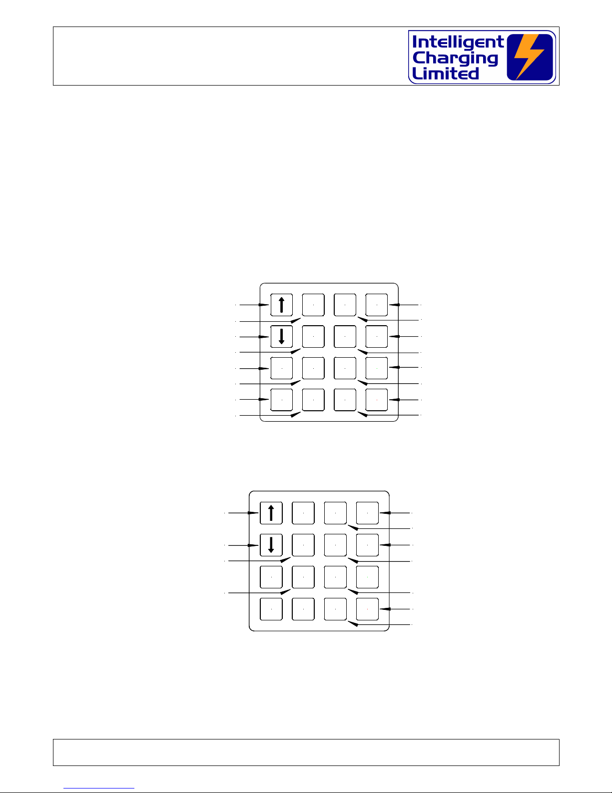
3.6 KEYBOARD
Each keypad on the unit controls only information for that channel, except when the
unit is put into ONE mode both keypads control the ONE mode of operation. The only
difference is that if a data entry function is invoked in the channel B keypad the data
entry will always have to be performed on the right hand keypad. There are 16 keys
on each keypad and each key performs a particular function depending if the channel
is running or stopped.
3.6.1 STOPPED KEY MAPPING
3.6.2 RUNNING KEY MAPPING
Increases Display Brighness
Reduces Display Brightness
2 X To Initiate CALIBRATION
Briefly Displays Battery Number
Cycles Through Displayed Data
Briefly Displays Battery Data
Breifly Displays The Battery AMPS
Breifly Displays The Battery VOLTS
Briefly Displays The Battery TIME
Manually STOPS The CHARGE/CAPACITY TEST
Breifly Displays The Battery MODE
EXTD
ENTR
DISP DATA
A SET PROC
V SETCHRG BATT
TEST ONE T SET
START
STOP
Note keys that have no comments against them do nothing while RUNNING
Doc: DWG1044-09-R16 TS25 MKII Operators manual.odt Page 10 of 46 Copyright Material of Intelligent Charging Limited © 2015
Printed On : 12/06/17
Increases Display Brighness
Reduces Display Brightness
Selects CAPACITY TEST MODE
Selects CHARGE MODE
2 X To Save Battery Data Into The LIBRARY
Selects A Battery From The LIBRARY
2 X Reset Parameters In The Unit
Cycles Through Displayed Data
Briefly Displays Battery Data
Enters The Battery AMPS
Enters The Battery VOLTS
Enters The Battery TIME
Starts CHARGE/CAPACITY TEST
Clears The Display And Alarm
On CHANNEL A (ONE) Selects ONE Mode
On CHANNEL B (MUTE) Stops The Audible Alarm
Enters The Battery MODE
EXTD
ENTR
DISP DATA
A SET PROC
V SETCHRG BATT
TEST ONE T SET
START
STOP

TS25 MKII : TS25-BAS1-KIT : TS25-BAS1-CAN-240
Battery charger/analyser : Operators Manual
4 USING THE TS25 MKII
4.1 CONNECTING BATTERIES
For all methods of use of the battery charger the battery to be tested or charged must
only be connected when the charger is either:
SWITCHED OFF
or
SWITCHED ON AND END LAMP ILLUMINATED
Connecting a battery while the charge is operational would damage the equipment,
and possible draw an electrical arc that, may cause an explosion from the venting
gases being emitted from the battery.
Care must also be executed in ensuring that the bared ends of the battery leads do
not come in contact with the metalwork of the charger as this may also cause
electrical arcing and or explosion risk.
WARNING
THE BATTERY SHOULD NEVER BE CONNECTED OR DISCONNECTED FROM THE
UNIT WHEN A CHARGE OR TEST IS IN PROGRESS AS ARCING CAN OCCUR
CAUSING AN EXPLOSION FROM GASSES VENTING FROM BATTERIES BEING
PROCESSED
THE BATTERY SHOULD ALWAYS BE ISOLATED FROM ANY EQUIPMENT
BEFORE BEING CONNECTED
Stray ground loops between the attached equipment and the TS25 MKII could cause
catastrophic damage to the unit and the attached equipment.
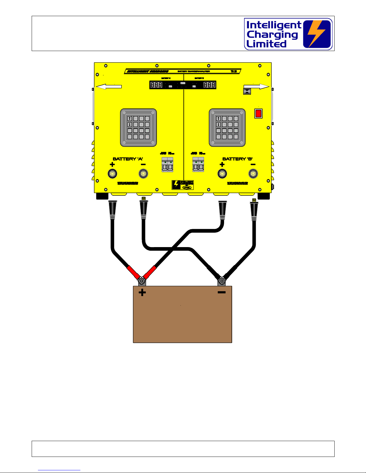
The battery or batteries must be connected to the TS25 MKII as shown in the
following diagram: -
Doc: DWG1044-09-R16 TS25 MKII Operators manual.odt Page 11 of 46 Copyright Material of Intelligent Charging Limited © 2015
Printed On : 12/06/17

TS25 MKII : TS25-BAS1-KIT : TS25-BAS1-CAN-240
Battery charger/analyser : Operators Manual
SINGLE OR TWIN CHANNEL BATTERY CONNECTION
Doc: DWG1044-09-R16 TS25 MKII Operators manual.odt Page 12 of 46 Copyright Material of Intelligent Charging Limited © 2015
Printed On : 12/06/17
AVIATION BATTERY
AVIATION BATTERY
BATTERY #1
BATTERY #2
DANGER
Disconnect the
mains supply before
removing this cover
MEM
Bxx
ON
OFF
I
O
MEM
Bxx
ON
OFF
I
O
MEM
Bxx
ON
OFF
I
O
MEM
Bxx
ON
OFF
I
O
VOLTS TIME
AMPS
TEST
END ONE
VOLTSTIME
AMPS
TEST
END
%
%
ALARM
POWER SWIT CH
POWER SWIT CH
POWER SWIT CH
POWER SWIT CH
KEEP AIRFLOW CLEAR
KEEP AIRFLOW CLEAR
KEEP AIRFLOW CLEAR
KEEP AIRFLOW CLEAR
10cm
10cm
10cm
10cm
KEEP AIRFLOW CLEAR
KEEP AIRFLOW CLEAR
KEEP AIRFLOW CLEAR
KEEP AIRFLOW CLEAR
10cm
10cm
10cm
10cm
EXTD
ENTR
DISP DATA
A SET PROC
V SETCHRG BATT
TEST ONE T SET
START
STOP MUTE
EXTD
ENTR
DISP DATA
A SET PROC
V SETCHRG BATT
TEST T SET
START
STOP
TS25 MKII : TS25-BAS1-KIT : TS25-BAS1-CAN-240
Battery charger/analyser : Operators Manual
BATTERY CONNECTION WHEN USING “ONE” MODE OF OPERATION
Doc: DWG1044-09-R16 TS25 MKII Operators manual.odt Page 13 of 46 Copyright Material of Intelligent Charging Limited © 2015
Printed On : 12/06/17
AVIATION BATTERY
DANGER
Disconnect the
mains supply before
removing this cover
MEM
Bxx
ON
OFFIO
MEM
Bxx
ON
OFFIO
MEM
Bxx
ON
OFFIO
MEM
Bxx
ON
OFFIO
VOLTS TIME
AMPS
TEST
END ONE
VOLTSTIME
AMPS
TEST
END
%
%
ALARM
POWER SWITCH
POWER SWITCHPOWER SWITCH
POWER SWITCH
KEEP AIRFLOW CLEAR
KEEP AIRFLOW CLEARKEEP AIRFLOW CLEAR
KEEP AIRFLOW CLEAR
10cm
10cm10cm
10cm
KEEP AIRFLOW CLEAR
KEEP AIRFLOW CLEARKEEP AIRFLOW CLEAR
KEEP AIRFLOW CLEAR
10cm
10cm10cm
10cm
EXTD
ENTR
DISP DATA
A SET PROC
V SETCHRG BATT
TEST ONE T SET
START
STOP MUTE
EXTD
ENTR
DISP DATA
A SET PROC
V SETCHRG BATT
TEST T SET
START
STOP

TS25 MKII : TS25-BAS1-KIT : TS25-BAS1-CAN-240
Battery charger/analyser : Operators Manual
4.2 CAPACITY TESTING BATTERIES
The main purpose of a capacity test is to establish that a battery under test can
maintain current output as specified by its ampere hour rating above a certain
terminal voltage.
As a rule of thumb a battery will maintain an output voltage5/6ths above its terminal
voltage for one hour if discharged at its ampere hour rating. A battery that can
maintain this is considered 100% or more of its rated capacity.
For example a 24V 20 A/H battery would be capacity tested at 20A for one hour and
have the voltage end point set to 20V. If after a one hour discharge at 20A the battery
terminal voltage was greater than 20V the battery would be considered at least 100%
efficient.
Intelligent Charging do not make any recommendations on what point a battery is
considered not efficient enough to be used, although a rule of thumb is that a battery
less than 80% should be discarded where it it's use is considered critical.
The TS25 MKII has two capacity test modes: -
Perform a capacity test only to the time period specified.
This mode will auto terminate the process if either the battery voltage reaches
the voltage end point, or if the total capacity test time is achieved. At the end of
the test the TS25 MKII will report a percentage of 100% or less depending on
why the capacity test was terminated.
Perform a capacity test until the final voltage is reached.
This mode will perform a capacity test until the voltage end point is reached. At
the end of test the TS25 MKII will report a percentage, which is the true
capacity of the battery, which may be more than 100%. This method is
sometimes employed so that records of battery deterioration over time or use
can be monitored.
4.2.1 MANUAL CAPACITY TEST
To perform a manual capacity test four parameters have to be programmed.
These are: -
Capacity test current (Amperes).
Capacity test time (Minutes)
Capacity test voltage end point (Volts)
Capacity test mode (Time or Volts)
Doc: DWG1044-09-R16 TS25 MKII Operators manual.odt Page 14 of 46 Copyright Material of Intelligent Charging Limited © 2015
Printed On : 12/06/17

TS25 MKII : TS25-BAS1-KIT : TS25-BAS1-CAN-240
Battery charger/analyser : Operators Manual
To program these values the TS25 MKII needs to powered and not performing
either a capacity test or charge on the channel to be used.
Press ASET to change the capacity test amperes.
Press VSET to change the capacity test voltage end point.
Press TSET to change the capacity test duration.
Press PROC to change the capacity test mode.
See section 4.4 ENTERING BATTERY DATA for details on how to enter the
required parameters.
4.2.2 LIBRARY CAPACITY TEST
To perform a capacity test from the library the library number has to be selected
first. To select the library number the following procedure has to be performed.
Press the BATT key. The display will show the current library item selected and
the rightmost digit will be flashing. Enter the library number by using the and
keys and the EXTD key to move to the next digit. Only library numbers 01 to
99 can be selected.
The TS25 MKII needs to be placed in capacity test mode by pressing TEST and
ensuring that the visual indicator TEST is illuminated.
4.2.3 REVIEWING CAPACITY TEST PARAMETERS
Once these values have been programmed into the unit they can be reviewed by
selecting the DISP key to cycle the display between VOLTS, AMPS,TIME and
% and then pressing the DATA key. This display will show the values
programmed in and the corresponding indicator will flash. Note when the %
indicator is lit there is no data to display. To check the capacity test mode simple
press the TEST key and the current capacity test mode will be displayed TIM or
VOL.
4.2.4 STARTING A CAPACITY TEST
Before a capacity test is performed for the first time it is important that the
parameters are reviewed using the reviewing feature above as incorrect
parameters could damage the battery under test.
Once satisfied that he data is correct the battery to undergo the capacity test
must be connected to the unit. Care must be taken when connecting batteries
which are not fitted with non reversible connectors, i.e. where the use of
crocodile clamps are implemented, as damage to the battery and or unit may
occur if a capacity test is started with reverse connection.
To begin the capacity test press START. The display will momentarily display
RUN, the END light will extinguish and it will then display battery voltage. During
the normal capacity test process the DISP key may be pressed to cycle the
display between
VOLTS, AMPS,TIME and %. The DATA key can also be
pressed to review the parameters programmed in for the current test under
Doc: DWG1044-09-R16 TS25 MKII Operators manual.odt Page 15 of 46 Copyright Material of Intelligent Charging Limited © 2015
Printed On : 12/06/17

TS25 MKII : TS25-BAS1-KIT : TS25-BAS1-CAN-240
Battery charger/analyser : Operators Manual
progress. If the TEST key is pressed this will briefly display the current test
mode.
4.2.5 STOPPING A CAPACITY TEST
At any time during the capacity test the process can be terminated by simply
pressing the STOP key. When the STOP key is pressed the process will be
terminated immediately and the display will show END and the END led will remain
illuminated.
The display will remain in this state until either MUTE of STOP is pressed.
4.2.6 CAPACITY TEST AUTO TERMINATE
If the capacity test has been programmed to auto terminate on time then the
process will automatically stop when either the battery voltage falls below the
voltage end point or when the capacity test time has elapsed.
If the capacity test has been programmed to auto terminate only when the
voltage falls below the voltage end point, then the process will stop when the
battery voltage falls below the voltage end point.
In both cases the capacity test process will terminate immediately, the audible
alarm will sound and the ALARM and END lights will illuminate and the display will
show the reason for terminating the process.
To clear the alarm the MUTE or STOP key must be pressed. Upon these being
pressed the display will show the actual capacity percent value.
Process termination codes:
E 1 The process time is complete.
E 2 Battery voltage has reached the voltage end point.
Doc: DWG1044-09-R16 TS25 MKII Operators manual.odt Page 16 of 46 Copyright Material of Intelligent Charging Limited © 2015
Printed On : 12/06/17

TS25 MKII : TS25-BAS1-KIT : TS25-BAS1-CAN-240
Battery charger/analyser : Operators Manual
4.3 CHARGING BATTERIES
To keep batteries in good condition it is important that correct charging procedures
are observed.
The TS25 MKII is an important tool in ensuring the its flexibility allows the user to
choose charge processes that are best suited to the battery. The TS25 MKII has two
inbuilt charging processes that suite a wide range of batteries.
The use of constant voltage charging is best suited to lead acid types of batteries and
the TS25 MKII controls constant voltage charging to ensure that no excess of current
can be driven into the batteries causing it damage.
Constant voltage charging is achieved by inserting a maximum specified current into a
battery until its terminal voltage reached the voltage set point. Once this voltage set
point has been reached the unit will reduce the current injected to maintain the
voltage set point. The charging process will continue until the charge time has
elapsed.
Constant current charging is employed mainly for Nickel Cadmium and Nickel Metal
hydride types if batteries, where a constant current can be driven into a battery for a
specified time and parameters can be set to prevent over charging.
Constant current charging is achieved by the unit driving a specified constant current
into the battery for a specified amount of time. During this time it will monitor the
battery voltage and auto terminate the process if this voltage is reached. This voltage
set point can be either the rise point of the battery or can be used as an over-voltage
parameter.
The TS25 MKII has a new charge mode implemented, which is more suitable to
alkaline batteries. In this mode known as Constant Current Plus mode the unit will
drive the constant current into the battery until the voltage set point is reached. Once
this point is reached the unit will continue charging at the same current for the time
specified.
4.3.1 MANUAL CHARGING
The unit required four parameters to perform a constant voltage charge. These
are: -
Maximum charge current (Amperes).
Charge time or charge additional time (Hours).
Voltage set point (Volts).
Charge mode.
To program these values the unit needs to powered and not performing either a
capacity test or charge on the channel to be used.
Press ASET to change the charge amperes.
Press VSET to change the charge test voltage set point.
Press TSET to change the charge duration or additional time.
Doc: DWG1044-09-R16 TS25 MKII Operators manual.odt Page 17 of 46 Copyright Material of Intelligent Charging Limited © 2015
Printed On : 12/06/17

TS25 MKII : TS25-BAS1-KIT : TS25-BAS1-CAN-240
Battery charger/analyser : Operators Manual
Press PROC to change the charge mode.
See section 4.4 ENTERING BATTERY DATA for details on how to enter the
required parameters.
4.3.2 LIBRARY CHARGING
To perform a charge from the library the library number has to be selected first.
To select the library number the following procedure has to be performed.
Press the BATT key. The display will show the current library item selected and
the rightmost digit will be flashing. Enter the library number by using the and
keys and the EXTD key to move to the next digit. Only library numbers 01 to
99 can be selected.
The unit needs to be placed in charge mode by pressing CHRG and ensuring that
the visual indicator TEST is extinguished.
4.3.3 REVIEWING CHARGE PARAMETERS
Once these values have been programmed into the unit they can be reviewed by
selecting the DISP key to cycle the display between VOLTS, AMPS and TIME
and then pressing the DATA key. This display will show the values programmed
in and the corresponding indicator will flash. To check the charge mode simply
press the CHRG key and the current charge mode will be displayed CV, CC or CCA.
4.3.4 STARTING A CHARGE
Before a charge is performed for the first time it is important that the parameters
are reviewed using the reviewing feature above as incorrect parameters could
damage the battery under charge.
Once satisfied that he data is correct the battery to undergo charging must be
connected to the unit. Care must be taken when connecting batteries which are
not fitted with non reversible connectors, i.e. where the use of crocodile clamps
are implemented, as damage to the battery and or TS25 MKII may occur if a
charge is started in reverse connection.
To begin the charge press START. The display will momentarily display RUN, the
END light will extinguish and it will then display battery voltage. During the
normal charge process the DISP key may be pressed to cycle the display
between VOLTS, AMPS and TIME. The DATA key can also be pressed to review
the parameters programmed in for the current test under progress. Pressing the
CHRG key will also briefly display the current charge mode.
4.3.5 STOPPING A CHARGE
At any time during the charge the process can be terminated by simply pressing
the STOP key. When the STOP key is pressed the process will be terminated
Doc: DWG1044-09-R16 TS25 MKII Operators manual.odt Page 18 of 46 Copyright Material of Intelligent Charging Limited © 2015
Printed On : 12/06/17

TS25 MKII : TS25-BAS1-KIT : TS25-BAS1-CAN-240
Battery charger/analyser : Operators Manual
immediately and the display will show END and the END led will remain
illuminated.
The display will remain in this state until either MUTE of STOP is pressed.
4.3.6 CHARGE PROCESS AUTO TERMINATE
If constant voltage charging the process will automatically stop when the test
time has been completed.
If constant current charging is programmed then the charge will terminate on the
full charge time completed or if the battery terminal voltage reached the voltage
set point.
If constant current with additional time mode is being performed then the unit
will stop when the additional time has been used or if the voltage set point is not
reached within 24 hours of the charge starting.
In all cases the charge process will terminate immediately, the audible alarm will
sound and the ALARM and END lights will illuminate and the display will show the
reason for terminating the process.
To clear the alarm the MUTE or STOP key must be pressed.
Process termination codes:
E 1 The process time or additional time is complete.
E 3 Voltage set point reached (Constant Current Mode Only).
E 4 The voltage set point has not been reached within 24Hours.
Doc: DWG1044-09-R16 TS25 MKII Operators manual.odt Page 19 of 46 Copyright Material of Intelligent Charging Limited © 2015
Printed On : 12/06/17

TS25 MKII : TS25-BAS1-KIT : TS25-BAS1-CAN-240
Battery charger/analyser : Operators Manual
4.4 ENTERING BATTERY DATA
In all cases of entering battery data the channel that data is to be entered on must be
in the stopped state. This is indicated by the END lamps being illuminated.
4.4.1 SETTING CAPACITY TEST MODE
Press PROC the display will flash the current mode on the display. Using the
and arrow keys the flashing display can be changed from TIM to VOL and visa
versa. Once selection has been made the ENTR key will be pressed to program
this parameter into the unit. If no change is required then simply pressing STOP
will clear the display.
TIM Programs the capacity testing mode to auto terminate when the battery
voltage falls below the voltage end point or when the time up has been
reached.
VOL Programs the capacity testing mode to only auto terminate when the
voltage end point has been reached.
4.4.2 SETTING THE CHARGE MODE
Press PROC the display will flash the current mode on the display. Using the
and arrow keys the flashing display can be changed from CV, CC and CCA and
visa versa. Once selection has been made the ENTR key will be pressed to
program this parameter into the unit. If no change is required then simply
pressing STOP will clear the display.
CV Programs the charge mode to perform a constant voltage charge where the
charge current is not exceeded until the voltage set point is reached at
which point it reduces current to maintain the voltage set point until the
charge time is completed.
CC Programs the charge mode to perform constant current charging for the
time specified terminating abnormally if the voltage set point is reached.
CCA Programs the charge mode to perform constant current charging until the
voltage set point is reached and then continue charging at the same current
until the additional time has elapsed.
4.4.3 ENTERING CURRENT DATA
Press the ASET key. The current setting will be displayed. The rightmost digit will
be flashing and can be modified by pressing the and arrow keys. Pressing
the EXTD key will cause the middle digit to flash and this can then be modified by
using the and arrow keys. Pressing the EXTD key again will cause the
leftmost digit to flash and this can then be modified using the and arrow
keys. If the EXTD key is pressed again the rightmost digit will then flash. This
cycle is repeated each time the EXTD key is pressed. The values cannot be
Doc: DWG1044-09-R16 TS25 MKII Operators manual.odt Page 20 of 46 Copyright Material of Intelligent Charging Limited © 2015
Printed On : 12/06/17

TS25 MKII : TS25-BAS1-KIT : TS25-BAS1-CAN-240
Battery charger/analyser : Operators Manual
modified to greater than 12.0A for charge mode and 25.0A for capacity test
mode.
Note: In ONE mode the maximum values that can be entered are 24.0A for
charge mode and 50.0A for capacity test mode.
4.4.4 ENTERING VOLTAGE DATA
Press the VSET key. The current setting will be displayed. The rightmost digit will
be flashing and can be modified by pressing the and arrow keys. Pressing
the EXTD key will cause the middle digit to flash and this can then be modified by
using the and arrow keys. Pressing the EXTD key again will cause the
leftmost digit to flash and this can then be modified using the and arrow
keys. If the EXTD key is pressed again the rightmost digit will then flash. This
cycle is repeated each time the EXTD key is pressed. The voltage value to be
entered cannot exceed 45.0V and the display will not allow digits to be
incremented above this amount.
4.4.5 ENTERING CAPACITY TEST TIME
Press the TSET key. The current setting will be displayed. The rightmost digit will
be flashing and can be modified by pressing the and arrow keys. Pressing
the EXTD key will cause the middle digit to flash and this can then be modified by
using the and arrow keys. Pressing the EXTD key again will cause the
leftmost digit to flash and this can then be modified using the and arrow
keys. If the EXTD key is pressed again the rightmost digit will then flash. This
cycle is repeated each time the EXTD key is pressed. The value entered is in
minutes and the maximum time that can be entered is 999 minutes.
4.4.6 ENTERING CHARGE TIME
Press the VSET key. The current setting will be displayed. The rightmost digit will
be flashing and can be modified by pressing the and arrow keys. Pressing
the EXTD key will cause the middle digit to flash and this can then be modified by
using the and arrow keys. Pressing the EXTD key again will cause the
leftmost digit to flash and this can then be modified using the and arrow
keys. If the EXTD key is pressed again the rightmost digit will then flash. This
cycle is repeated each time the EXTD key is pressed. The value entered is in
hours and the maximum time than can be entered in 99.9H.
Doc: DWG1044-09-R16 TS25 MKII Operators manual.odt Page 21 of 46 Copyright Material of Intelligent Charging Limited © 2015
Printed On : 12/06/17

TS25 MKII : TS25-BAS1-KIT : TS25-BAS1-CAN-240
Battery charger/analyser : Operators Manual
4.5 USING THE ONE MODE OF OPERATION
The TS25MKII has a special feature in that if higher currents for charging or capacity
testing are required the unit can be "paralleled". Using special paired cables, which
connect, channel A and channel B together both channels can be used in unison.
WARNING
PAY CAREFUL ATTENTION TO BATTERY CONNECTION
WHEN USING “ONE” MODE
Control of the unit is all achieved through the use of the channel A keypad and the
channel B keypad only mimics some of the channel A functions. The channel B display
will change to an alternative display to channel A when the DISP key is pressed.
All operation of the equipment is the same as when using an individual channel, with
the exception that higher currents can be entered for capacity testing and charging.
If a library item has been written in one mode, it will only be recalled in ONE mode if
the current exceeds the single channel limitations of the unit.
Certain actions cannot be performed in ONE mode and these are reported on the
display in the form of an error message and buzzer sound.
4.6 RESETTING THE TS25 MKII
The TS25 MKII keeps users modified data in battery backed RAM. It may be necessary
at some time to reset this data to the defaults. Three sets of data can be reset.
4.6.1 GENERAL PARAMETER DATA
The general parameter data covers the current battery data that is set and
indicators to general unit operation. It is not usually necessary to reset this data
as is checked internally for correctness, but when the unit has been serviced and
the battery backup removed the general parameter data can be come corrupt
and may need resetting through the use of this function.
4.6.2 DEFAULT LIBRARY DATA
The operator may want at some time to reset the internal data library back to
the default battery library, this function copies the internal library into the user
definable battery library. Warning: The use of this function will remove all user
defined library items.
4.6.3 CALIBRATION PARAMETERS
Doc: DWG1044-09-R16 TS25 MKII Operators manual.odt Page 22 of 46 Copyright Material of Intelligent Charging Limited © 2015
Printed On : 12/06/17

TS25 MKII : TS25-BAS1-KIT : TS25-BAS1-CAN-240
Battery charger/analyser : Operators Manual
After unit servicing where the battery-backed memory has been reset the
calibration parameters may become corrupt and need resetting to enable the unit
to operate correctly so that a correct calibration can be performed. The default
calibration values are correct at time of manufacture, but in time as components
deteriorate re-calibration will be necessary to keep output to specified tolerances.
4.6.4 SELECTING RESET MODE
To perform this function both channels must be STOPPED. Press EXTD twice
rapidly. The display will flash three numeric digits. These correspond to the
firmware release of the unit. By pressing the and arrow keys the display can
be changed to show PRS, LRS or CRS. Once selection is made on the display the
ENTR key must be pressed to invoke the operation. If the operation needs to be
cancelled i.e. if confirmation of firmware revision number is all that was needed
then hitting the STOP key will abort the reset mode.
PRS Parameter Reset.
LRS Library Reset
CRS Calibration Reset
Doc: DWG1044-09-R16 TS25 MKII Operators manual.odt Page 23 of 46 Copyright Material of Intelligent Charging Limited © 2015
Printed On : 12/06/17

TS25 MKII : TS25-BAS1-KIT : TS25-BAS1-CAN-240
Battery charger/analyser : Operators Manual
4.7 DISPLAY MNEMONICS
The following is a list of all the display mnemonics, which appear on the unit together
with a short description for their appearance.
Mnemonic Description
LIB
Battery data has been written back to the library.
RUN
A Charge or Capacity test has just been started.
END
A Charge or Capacity test has been stopped by the
STOP key.
CAL
Calibration mode has been selected.
PRS
Parameter reset selection or action.
LRS
Library reset selection or action.
CRS
Calibration reset selection or action.
TIM
Capacity test terminated on time selection or setting
VOL
Capacity test terminates on voltage set point only
selection or setting.
CV
Constant voltage charge selection or setting.
CC
Constant current charge selection or setting.
CCA
Constant current charge with additional time on voltage
set point selection or setting.
Doc: DWG1044-09-R16 TS25 MKII Operators manual.odt Page 24 of 46 Copyright Material of Intelligent Charging Limited © 2015
Printed On : 12/06/17

TS25 MKII : TS25-BAS1-KIT : TS25-BAS1-CAN-240
Battery charger/analyser : Operators Manual
4.8 ERROR CODES
Mnemonic Description
E 1
Charge or Capacity test time up completed. Indicates
that either a charge or capacity test has completed its
allotted time.
E 2
Capacity test voltage end point reached. Indicated that
the battery voltage has reached the voltage end point
and the capacity test has stopped.
E 3
Constant Current charge voltage set point met.
Indicates that the battery voltage has reached the
voltage set point.
E 4
Constant current additional time mode voltage set point
not reached with 24 hours. In this mode the unit will not
allow a constant charge to be permitted for more that
24Hrs, it is possible that the battery undergoing charge
has the wrong data set or has developed an internal
fault.
E 5
Error in voltage calibration data input. When the voltage
data is input to the unit it check to ensure that the
calibration scale factor falls within specified boundaries
to prevent inadvertently entered wrong values being
used. If this error is received repeatedly when
calibrating it also indicates that the unit has a
malfunction and requires service.
E 6
Error in current calibration data input. When the current
data is input to the unit it check to ensure that the
calibration scale factor falls within specified boundaries
to prevent inadvertently entered wrong values being
used. If this error is received repeatedly when
calibrating it also indicates that the unit has a
malfunction and requires service.
E 7
Voltage imbalance in ONE mode. When running in ONE
mode the unit checks the difference in voltage between
channel A and channel B. If this condition is met it
means that one channel has not been connected or that
calibration needs to be checked.
E 8
Library item recalled needs ONE mode and a charge or
test is being performed. When a library item has been
selected which required ONE mode this condition will be
displayed if either channel A or channel B is currently
Doc: DWG1044-09-R16 TS25 MKII Operators manual.odt Page 25 of 46 Copyright Material of Intelligent Charging Limited © 2015
Printed On : 12/06/17

TS25 MKII : TS25-BAS1-KIT : TS25-BAS1-CAN-240
Battery charger/analyser : Operators Manual
undergoing a charge or capacity test.
E 9
No battery voltage detected. Either battery open circuit
voltage is below 0.4V, reversed or has been
disconnected during operation.
E10
This error occurs if the unit detects current settings
greater than the capacity of the unit.
E11
Current overload in capacity test mode detected. Occurs
when a battery voltage and current combination exceeds
750W per channel.
E12
Internal demand low error. This indicates a fault where
the actual current is more than 10A of expected current.
E13
This code is displayed when the unit is first powered and
is an indication that the internal battery needs replacing.
Note that when this occurs the unit will have loaded it’s
default calibration data and re-calibration after battery
replacement will be required.
E14
Charging or Capacity Testing has stopped because the
unit cannot detect any amps flowing.
E15
While constant voltage charging if the charger detects a
battery voltage 10V greater that the target voltage the
unit will stop and report this warning.
Doc: DWG1044-09-R16 TS25 MKII Operators manual.odt Page 26 of 46 Copyright Material of Intelligent Charging Limited © 2015
Printed On : 12/06/17

TS25 MKII : TS25-BAS1-KIT : TS25-BAS1-CAN-240
Battery charger/analyser : Operators Manual
5 CALIBRATION
It is recommended that during the yearly routine maintenance the calibration check is
performed to ensure that the battery charger and capacity tester is still performing to its
specifications. The following procedure should be observed in order to perform this check.
5.1 EQUIPMENT REQUIRED
In addition to the TS25 MKII that is going to undergo a calibration check, the following
is a list of equipment that will be required to perform the calibration routines.
• A ammeter shunt such as the Intelligent Charging SHUNT60A or any ammeter
shunt combination capable of at least 60A measurement to one decimal place.
• A milli-voltmeter to be used in conjunction with the SHUNT60A set to read millivolts between 0 and 60mV with a resolution of no less that 0.1mV.
• A voltmeter capable of measuring the voltage from a 24V battery and with a
resolution of no less that 0.1V.
• A test battery of good condition which is capable of being charged for a short
duration at 10A and can be used in capacity test mode at 25A. A 25A or Lead Acid
battery of 25A/H is recommended.
5.2 PERFORMANCE CHECKING
There are two stages in the recalibration. The initial stage is to check that the TS25
MKII is still working within the correct performance characteristics. If the unit is still
working within tolerance then re-calibration does not need to be performed.
Performance checking will then not need to be done for another year.
To execute a performance check the following procedure must be observed.
5.2.1 Charge Calibration Check:
Connect the measuring equipment in accordance with the calibration equipment
connection diagram to Channel A.
• Set the battery charger to CHRG mode.
• Set the charge mode to CC using the PROC key.
• Set charge amps to 10A using the ASET key.
• Set the voltage threshold to 30V using the VSET key.
• Set the charge duration to 0.1H using the TSET key.
• Press START to begin the charge process.
• Allow the charge current to stabilise.
• Take note of the readings of both the measurement equipment and the
readings on the charger display.
• If the readings are more than 1 digit different then the recalibration procedure
must be followed to correct the difference.
• Once this process is completed press STOP to end the charge.
• Charge circuit calibration is complete.
• This process must then be completed for channel B.
Doc: DWG1044-09-R16 TS25 MKII Operators manual.odt Page 27 of 46 Copyright Material of Intelligent Charging Limited © 2015
Printed On : 12/06/17

TS25 MKII : TS25-BAS1-KIT : TS25-BAS1-CAN-240
Battery charger/analyser : Operators Manual
5.2.2 Capacity Test Calibration Check.
Connect the measuring equipment in accordance with the calibration equipment
connection diagram to Channel A.
• Set the battery charger to test mode.
• Set capacity test amps to 25A using the ASET key.
• Set the termination voltage to 20V using the VSET key.
• Set the capacity test duration to 010 using the TSET key.
• Press START to begin the capacity test process.
• Allow the capacity test current to stabilise.
• Take note of the readings of both the measurement equipment and the
readings on the charger display.
• If the readings are more than 1 digit different then the recalibration procedure
must be followed to correct the difference.
• Once this process is completed press STOP to end the capacity test.
• Capacity test circuit calibration is complete.
• This process must then be completed for channel B.
5.3 RE-CALIBRATION
The TS25 MKII keeps a calibration constant value stored internally which it uses for
calculating true voltage and current from it’s internal measurement circuitry. Because
of component tolerances and tolerance drift with time (decay) the values created at
manufacturing time can cause measurement errors due to this decay. Modern
components are much more stable than their older counterparts so re-calibration is
less necessary, but the checking is essential to ensure that the correct voltages and
currents are used to charge and capacity test your batteries.
If the procedures identified above requires the unit to be recalibrated then the
following re-calibration method needs to be followed.
5.3.1 Charge Re-Calibration:
Connect the measuring equipment in accordance with the calibration equipment
connection diagram to Channel A.
• Set the battery charger to CHRG mode.
• Set the charge mode to CC using the PROC key.
• Set charge amps to 10A using the ASET key.
• Set the voltage threshold to 30V using the VSET key.
• Set the charge duration to 0.1H using the TSET key.
• Press START to begin the charge process.
• Allow the charge current to stabilise.
• Press the ENTR key rapidly twice
• The display will briefly display CAL.
• To re-calibrate current press ASET.
• Enter the number of amps displayed on the measuring equipment, then press
ENTR.
• The charger will adjust the charge amps so that the measuring equipment will
then display the same as the charger.
• To recalibrate voltage press VSET
• Enter the number of volts as displayed on the measuring equipment and press
ENTR.
Doc: DWG1044-09-R16 TS25 MKII Operators manual.odt Page 28 of 46 Copyright Material of Intelligent Charging Limited © 2015
Printed On : 12/06/17

TS25 MKII : TS25-BAS1-KIT : TS25-BAS1-CAN-240
Battery charger/analyser : Operators Manual
• The charger display will then adjust the display to show the same reading as
the measuring equipment.
• Once the process is completed press STOP to end the charge.
• Charge circuit calibration is complete.
• If necessary the same process is performed for channel B.
5.3.2 Capacity Test Re-Calibration.
Connect the measuring equipment in accordance with the calibration equipment
connection diagram to Channel A.
• Set the battery charger to test mode.
• Set capacity test amps to 25A using the ASET key.
• Set the termination voltage to 20V using the VSET key.
• Set the capacity test duration to 010 using the TSET key.
• Press START to begin the capacity test process.
• Allow the capacity test current to stabilise.
• Press the ENTR key rapidly twice
• The display will briefly display CAL.
• To re-calibrate current press ASET.
• Enter the number of amps displayed on the measuring equipment, then press
ENTR.
• The charger will adjust the charge amps so that the measuring equipment will
then display the same as the charger.
• To recalibrate voltage press VSET
• Enter the number of volts as displayed on the measuring equipment and press
ENTR.
• The charger display will then adjust the display to show the same reading as
the measuring equipment.
• Once this process is completed press STOP to end the capacity test.
• Capacity test circuit calibration is complete.
• If necessary the same process is performed for channel B.
5.4 CALIBRATION PROBLEMS
The TS25 MKII has in-built protection to prevent erroneous calibration data from being
entered.
When performing a re-calibration the unit will validate the data to ensure that it is
within reasonable boundaries. If when entering measurements into the unit it beeps
and displays E 6 then the volts or amps you are trying to enter are invalid.
If the same error is displayed on repeat attempts it is an indication of a breakdown in
the internal circuitry and the unit will need to be quarantined and returned to
Intelligent Charging for service.
Doc: DWG1044-09-R16 TS25 MKII Operators manual.odt Page 29 of 46 Copyright Material of Intelligent Charging Limited © 2015
Printed On : 12/06/17

TS25 MKII : TS25-BAS1-KIT : TS25-BAS1-CAN-240
Battery charger/analyser : Operators Manual
5.5 CALIBRATION EQUIPMENT CONNECTIONS
Doc: DWG1044-09-R16 TS25 MKII Operators manual.odt Page 30 of 46 Copyright Material of Intelligent Charging Limited © 2015
Printed On : 12/06/17
INTELLIGENT CHARGING
SHUNT60A
AVIATION BATTERY 24V 25A/H
200m
2
20
200
1000
V d.c.
700
200
20
200m
V a.c.
200u
2m
20m
200m
2
10
A a.c.
10
2
200m
20m
2m
200u
20u
OFF
20m
DIGITAL MULTIMETER DMM01
AMPS
DMM SET TO READ 0-20mV
VOLTS
DMM SET TO READ 0-200V
200m
2
20
200
1000
V d.c.
700
200
20
200m
V a.c.
200u
2m
20m
200m
2
10
A a.c.
10
2
200m
20m
2m
200u
20u
OFF
20m
DIGITAL MULTIMETER DMM01
DANGER
Disconnect the
mains supply before
removing this cover
MEM
Bxx
ON
OFF
I
O
MEM
Bxx
ON
OFF
I
O
MEM
Bxx
ON
OFF
I
O
MEM
Bxx
ON
OFF
I
O
VOLTS TIME
AMPS
TEST
END ONE
VOLTSTIME
AMPS
TEST
END
%%
ALARM
POWER SWITCH
POWER SWITCH
POWER SWITCH
POWER SWITCH
KEEP AIRFLOW C LEAR
KEEP AIRFLOW C LEAR
KEEP AIRFLOW C LEAR
KEEP AIRFLOW C LEAR
10cm
10cm
10cm
10cm
KEEP AIRFLOW C LEAR
KEEP AIRFLOW C LEAR
KEEP AIRFLOW C LEAR
KEEP AIRFLOW C LEAR
10cm
10cm
10cm
10cm
EXTD
ENTR
DISP DATA
A SET PROC
V SETCHRG BATT
TEST ONE T SET
START
STOP MUTE
EXTD
ENTR
DISP DATA
A SET PROC
V SETCHRG BATT
TEST T SET
START
STOP

TS25 MKII : TS25-BAS1-KIT : TS25-BAS1-CAN-240
Battery charger/analyser : Operators Manual
6 ROUTINE MAINTENANCE
Your TS25 MKII is designed to give you many years of trouble free use and Intelligent
Charging recommends that at least once per year the following routine maintenance checks
should be followed.
• Perform a calibration check as covered in the CALIBRATION section.
• Ensure that the cooling fans can run freely and are not clogged with dust and dirt.
• Ensure that all the inlet vents are free from obstructions and if necessary clear any
obstructions.
• Inspect the battery leads to ensure that the connections are still sound and there is no
evidence of fraying of cable strands at the connectors and no build up of corrosion due
to battery acid or alkaline. If the connectors are broken or damaged they should be
replaced. Replacement charger connectors can be purchased from Intelligent Charging.
• Inspect the power cord for damage and replace if necessary.
• If required by local regulations perform a PAT test on the equipment in accordance with
the regulations in force.
6.1 INTERNAL BATTERY REPLACEMENT
The internal parameters of the TS25 MKII are maintained by a single coin cell
mounted on the display PCB at the front of the unit. This should be changed every 5-6
years. If it should fail during use the error code E13 will be displayed when power is
applied to the unit.
The cell is a standard Lithium button cell number CR2024. When replacing
the battery please observe the correct methods of disposal of the old
battery in accordance with your local regulations.
Doc: DWG1044-09-R16 TS25 MKII Operators manual.odt Page 31 of 46 Copyright Material of Intelligent Charging Limited © 2015
Printed On : 12/06/17

TS25 MKII : TS25-BAS1-KIT : TS25-BAS1-CAN-240
Battery charger/analyser : Operators Manual
7 BATTERY LIBRARY
The TS25 MKII has 99 sets of built in data, which can be recalled quickly to perform both
charging and capacity testing. Recalling library data is covered in the sections on capacity
testing and charging.
7.1 RETRIEVING A LIBRARY ITEM
Press the BATT key. The display will show the current library item selected and
the rightmost digit will be flashing. Enter the library number by using the and
keys and the EXTD key to move to the next digit. Only library numbers 01 to
99 can be selected.
The leftmost digit is used to select which library database the item is to be
retrieved from.
'0' Indicates that the item is to be retrieved from the user data base where
items can be modified.
'1' Indicates that the item is to be retrieved from the units internal fixed
battery library. Items from this database cannot be written back.
As supplied or when a library reset is performed the modifiable database is the
same as the un-modifiable database.
7.2 ENTERING OR MODIFYING A LIBRARY ENTRY
In order for a library item to be modified it must be recalled first, modified, and
then written back.
Recall the library item you wish to modify using the procedure above.
Follow the procedures for manual charging or capacity testing to set the ASET,
VSET and TSET and PROC parameters.
Once these have been reviewed the battery library data can be written back by
pressing the ENTR key rapidly twice. This means the ENTR key must be pressed
twice within 0.6 Second. The display will briefly show LIB to confirm that the item
has been applied to the units’ internal memory.
Doc: DWG1044-09-R16 TS25 MKII Operators manual.odt Page 32 of 46 Copyright Material of Intelligent Charging Limited © 2015
Printed On : 12/06/17
TS25 MKII : TS25-BAS1-KIT : TS25-BAS1-CAN-240
Battery charger/analyser : Operators Manual
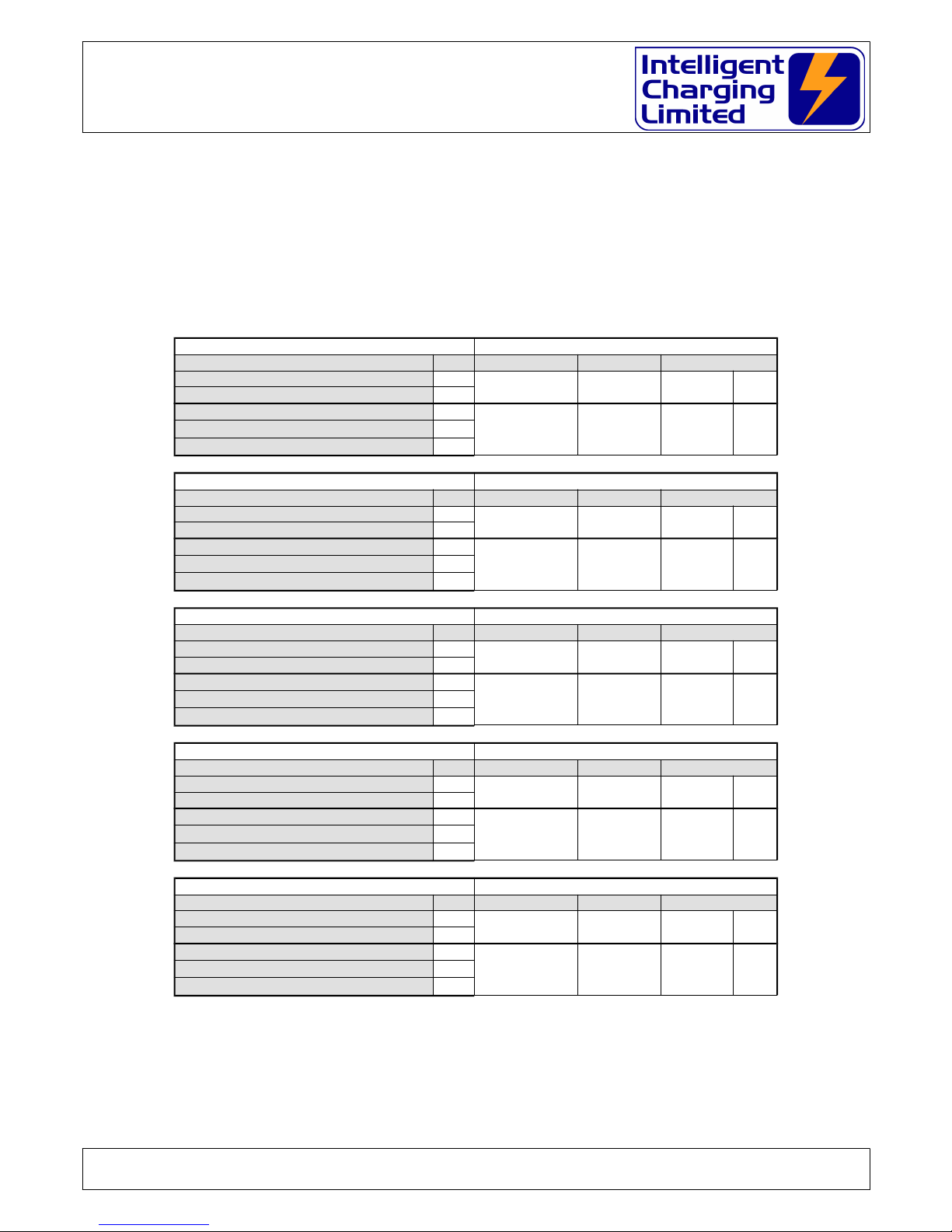
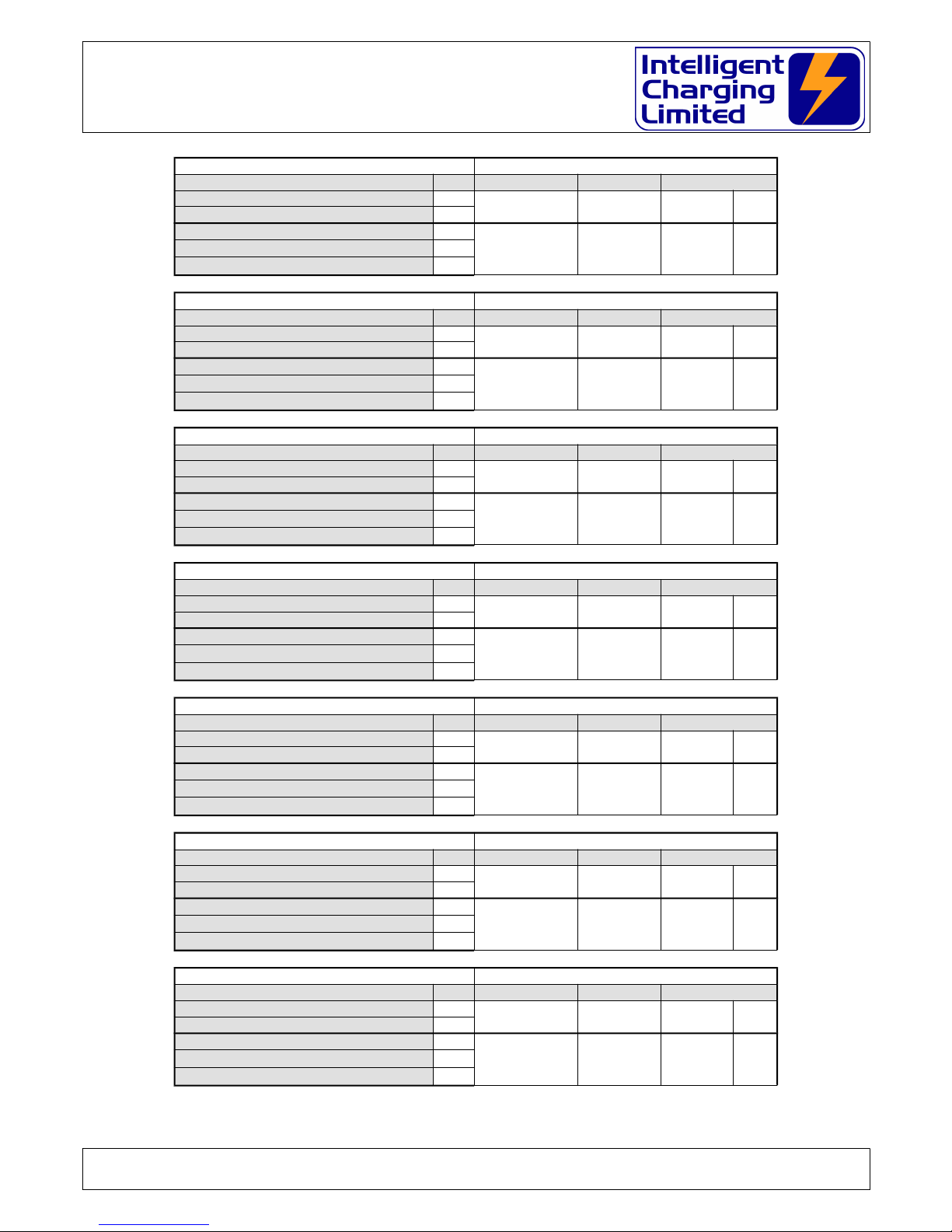
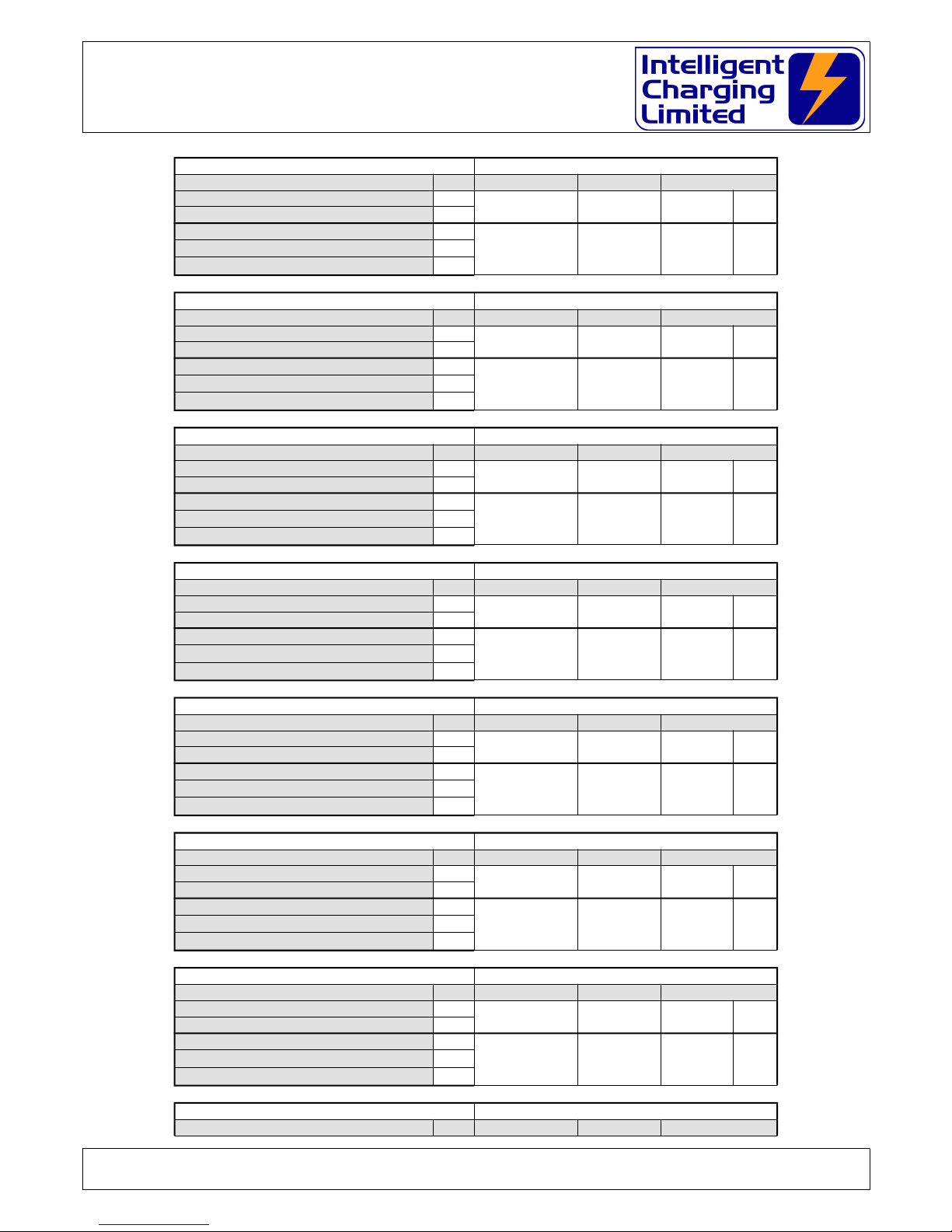
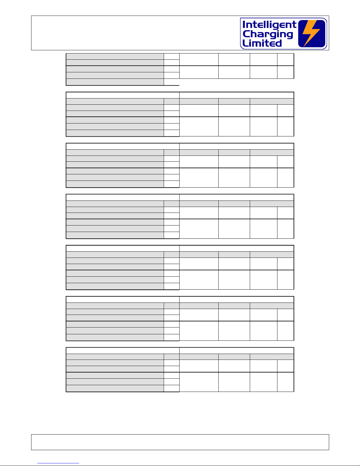
8 DEFAULT BATTERY LIBRARY
The TS25 MKII comes with a built in list of battery parameters of commonly used batteries.
Intelligent Charging provides this list as guidelines only and do not take any responsibility for
the fitness of purpose of these parameters. In all cases the operator must ensure that any
parameters selected are suitable for the battery being charged or capacity tested. Always
refer to the manufacturers data sheets for proper care and use of batteries.
00 USER
MODE
VOLTS AMPS TIME
Captest on time
0.0 0.0 60 m
Captest on voltage
Constant Voltage Charge
0.0 0.0 0.0 hConstant Current Charge
C C Charge with Additional Time
01 CONCORDE BB 638/U
MODE
VOLTS AMPS TIME
Captest on time
21.0 31.0 60 m
Captest on voltage
Constant Voltage Charge
29.0 20.0 6.0 hConstant Current Charge
C C Charge with Additional Time
02 HAWKER 9750T0663
MODE
VOLTS AMPS TIME
Captest on time
20.0 25.0 60 m
Captest on voltage
Constant Voltage Charge
29.0 20.0 6.0 hConstant Current Charge
C C Charge with Additional Time
03 OLDHAM
MODE
VOLTS AMPS TIME
Captest on time
10.0 50.0 60 m
Captest on voltage
Constant Voltage Charge
14.5 20.0 8.0 hConstant Current Charge
C C Charge with Additional Time
04 SONNENSCHEIN A512/6.5S
MODE
VOLTS AMPS TIME
Captest on time
10.0 6.5 60 m
Captest on voltage
Constant Voltage Charge
14.4 3.25 4.0 hConstant Current Charge
C C Charge with Additional Time
Doc: DWG1044-09-R16 TS25 MKII Operators manual.odt Page 33 of 46 Copyright Material of Intelligent Charging Limited © 2015
Printed On : 12/06/17
TS25 MKII : TS25-BAS1-KIT : TS25-BAS1-CAN-240
Battery charger/analyser : Operators Manual
05 SONNENSCHEIN A512/24
MODE
VOLTS AMPS TIME
Captest on time
20.0 24.0 60 m
Captest on voltage
Constant Voltage Charge
28.8 15.0 6.0 hConstant Current Charge
C C Charge with Additional Time
06 SONNENSCHEIN A506/10S
MODE
VOLTS AMPS TIME
Captest on time
10.0 5.0 60 m
Captest on voltage
Constant Voltage Charge
7.25 5.0 4.0 hConstant Current Charge
C C Charge with Additional Time
07 SONNENSCHEIN A200
MODE
VOLTS AMPS TIME
Captest on time
10.0 40.0 60 m
Captest on voltage
Constant Voltage Charge
14.4 20.0 8.0 hConstant Current Charge
C C Charge with Additional Time
08 HAWKER ENERGY 9750D07545
MODE
VOLTS AMPS TIME
Captest on time
20.0 18.0 60 m
Captest on voltage
Constant Voltage Charge
29.0 9.0 4.0 hConstant Current Charge
C C Charge with Additional Time
09 YUASA NP-24-12B
MODE
VOLTS AMPS TIME
Captest on time
10.0 24.0 60 m
Captest on voltage
Constant Voltage Charge
14.4 20.0 6.0 hConstant Current Charge
C C Charge with Additional Time
10 CIBL 6XNM11WL
MODE
VOLTS AMPS TIME
Captest on time
10.0 32.0 60 m
Captest on voltage
Constant Voltage Charge
14.5 20.0 8.0 hConstant Current Charge
C C Charge with Additional Time
11 AC DELKO 30-55
MODE
VOLTS AMPS TIME
Captest on time
10.0 55.0 60 m
Captest on voltage
Constant Voltage Charge
14.5 20.0 8.0 hConstant Current Charge
C C Charge with Additional Time
Doc: DWG1044-09-R16 TS25 MKII Operators manual.odt Page 34 of 46 Copyright Material of Intelligent Charging Limited © 2015
Printed On : 12/06/17

TS25 MKII : TS25-BAS1-KIT : TS25-BAS1-CAN-240
Battery charger/analyser : Operators Manual
12 TUNGSTONE 12C48
MODE
VOLTS AMPS TIME
Captest on time
10.0 48.0 60 m
Captest on voltage
Constant Voltage Charge
14.5 20.0 8.0 hConstant Current Charge
C C Charge with Additional Time
13 LUCAS 15
MODE
VOLTS AMPS TIME
Captest on time
10.0 50.0 60 m
Captest on voltage
Constant Voltage Charge
14.5 20.0 8.0 hConstant Current Charge
C C Charge with Additional Time
14 SONNENSCHIEN A508/3.5S
MODE
VOLTS AMPS TIME
Captest on time
6.7 3.5 60 m
Captest on voltage
Constant Voltage Charge
9.6 2.0 4.0 hConstant Current Charge
C C Charge with Additional Time
15 GATES ENERGY 0809-0010
MODE
VOLTS AMPS TIME
Captest on time
3.3 5.0 60 m
Captest on voltage
Constant Voltage Charge
4.85 2.0 4.0 hConstant Current Charge
C C Charge with Additional Time
16 YUASA NP2.6-6
MODE
VOLTS AMPS TIME
Captest on time
5.0 2.6 60 m
Captest on voltage
Constant Voltage Charge
7.25 1.0 4.0 hConstant Current Charge
C C Charge with Additional Time
17 AC DELCO 20-55
MODE
VOLTS AMPS TIME
Captest on time
10.0 27.5 120 m
Captest on voltage
Constant Voltage Charge
14.5 20.0 8.0 hConstant Current Charge
C C Charge with Additional Time
18 HAWKER 9750-0741
MODE
VOLTS AMPS TIME
Captest on time
20.0 18.0 60 m
Captest on voltage
Constant Voltage Charge
29.0 20.0 4.0 hConstant Current Charge
C C Charge with Additional Time
19 HAWKER ENERGY 9750F0540
MODE
VOLTS AMPS TIME
Doc: DWG1044-09-R16 TS25 MKII Operators manual.odt Page 35 of 46 Copyright Material of Intelligent Charging Limited © 2015
Printed On : 12/06/17

TS25 MKII : TS25-BAS1-KIT : TS25-BAS1-CAN-240
Battery charger/analyser : Operators Manual
Captest on time
20.0 40.0 60 m
Captest on voltage
Constant Voltage Charge
29.0 20.0 8.0 hConstant Current Charge
C C Charge with Additional Time
20 YUASA NP4-6
MODE
VOLTS AMPS TIME
Captest on time
5.0 4.0 60 m
Captest on voltage
Constant Voltage Charge
7.25 2.0 4.0 hConstant Current Charge
C C Charge with Additional Time
21 HAWKER 9750-0647
MODE
VOLTS AMPS TIME
Captest on time
20.0 25.0 60 m
Captest on voltage
Constant Voltage Charge
29.0 20.0 6.0 hConstant Current Charge
C C Charge with Additional Time
22 HAWKER 9750-0751
MODE
VOLTS AMPS TIME
Captest on time
20.0 25.0 60 m
Captest on voltage
Constant Voltage Charge
29.0 18.0 6.0 hConstant Current Charge
C C Charge with Additional Time
23 OLDHAM CROMPTON 4V10
MODE
VOLTS AMPS TIME
Captest on time
3.3 10.0 60 m
Captest on voltage
Constant Voltage Charge
4.85 5.0 4.0 hConstant Current Charge
C C Charge with Additional Time
24 HAWKER ENERGY 97500640
MODE
VOLTS AMPS TIME
Captest on time
20.0 25.0 60 m
Captest on voltage
Constant Voltage Charge
29.0 20.0 6.0 hConstant Current Charge
C C Charge with Additional Time
25 OLDHAM C
MODE
VOLTS AMPS TIME
Captest on time
10.8 40.0 60 m
Captest on voltage
Constant Voltage Charge
14.5 20.0 8.0 hConstant Current Charge
C C Charge with Additional Time
Doc: DWG1044-09-R16 TS25 MKII Operators manual.odt Page 36 of 46 Copyright Material of Intelligent Charging Limited © 2015
Printed On : 12/06/17

TS25 MKII : TS25-BAS1-KIT : TS25-BAS1-CAN-240
Battery charger/analyser : Operators Manual
26 CHLORIDE 6 MNA 17
MODE
VOLTS AMPS TIME
Captest on time
10.8 2.5 60 m
Captest on voltage
Constant Voltage Charge
14.5 1.0 4.0 hConstant Current Charge
C C Charge with Additional Time
27 YUASA NP38-12
MODE
VOLTS AMPS TIME
Captest on time
10.0 38.0 60 m
Captest on voltage
Constant Voltage Charge
14.4 20.0 8.0 hConstant Current Charge
C C Charge with Additional Time
28 HAWKER ENERGY 9750T0675
MODE
VOLTS AMPS TIME
Captest on time
20.0 25.0 60 m
Captest on voltage
Constant Voltage Charge
29.0 20.0 6.0 hConstant Current Charge
C C Charge with Additional Time
29 MARATHON CA54-3
MODE
VOLTS AMPS TIME
Captest on time
19.0 5.5 60 m
Captest on voltage
Constant Voltage Charge
29.0 0.5 2.0 hConstant Current Charge
C C Charge with Additional Time
30 GRIMES 61-0478-1
MODE
VOLTS AMPS TIME
Captest on time
0.0 0.0 0 m
Captest on voltage
Constant Voltage Charge
11.0 0.3 16.0 hConstant Current Charge
C C Charge with Additional Time
31 LITTON 51008
MODE
VOLTS AMPS TIME
Captest on time
19.0 14.0 60 m
Captest on voltage
Constant Voltage Charge
29.45 3.0 5.0 hConstant Current Charge
C C Charge with Additional Time
32 GRIMES 61-2275-1
MODE
VOLTS AMPS TIME
Captest on time
14.0 0.75 60 m
Captest on voltage
Constant Voltage Charge
20.0 0.75 2.0 hConstant Current Charge
C C Charge with Additional Time
33 SAFT 715737-2
MODE
VOLTS AMPS TIME
Doc: DWG1044-09-R16 TS25 MKII Operators manual.odt Page 37 of 46 Copyright Material of Intelligent Charging Limited © 2015
Printed On : 12/06/17

TS25 MKII : TS25-BAS1-KIT : TS25-BAS1-CAN-240
Battery charger/analyser : Operators Manual
Captest on time
24.0 1.9 60 m
Captest on voltage
Constant Voltage Charge
36.0 0.38 4.0 h
Constant Current Charge
C C Charge with Additional Time
34 VARTA F19/40H1
MODE
VOLTS AMPS TIME
Captest on time
19.0 36.0 60 m
Captest on voltage
Constant Voltage Charge
28.5 3.6 5.0 hConstant Current Charge
C C Charge with Additional Time
35 VARTA F20/25H1
MODE
VOLTS AMPS TIME
Captest on time
20.0 23.0 60 m
Captest on voltage
Constant Voltage Charge
30.0 2.3 5.0 hConstant Current Charge
C C Charge with Additional Time
36 VARTA F20/40H1WT
MODE
VOLTS AMPS TIME
Captest on time
20.0 36.0 60 m
Captest on voltage
Constant Voltage Charge
30.0 8.0 2.0 hConstant Current Charge
C C Charge with Additional Time
37 VARTA F20/40H1CWT
MODE
VOLTS AMPS TIME
Captest on time
20.0 36.0 60 m
Captest on voltage
Constant Voltage Charge
30.0 8.0 2.0 hConstant Current Charge
C C Charge with Additional Time
38 VARTA F20/40H1C
MODE
VOLTS AMPS TIME
Captest on time
20.0 36.0 60 m
Captest on voltage
Constant Voltage Charge
30.0 8.0 2.0 hConstant Current Charge
C C Charge with Additional Time
39 SAFT 400A1
MODE
VOLTS AMPS TIME
Captest on time
20.0 40.0 60 m
Captest on voltage
Constant Voltage Charge
30.0 4.0 5.0 hConstant Current Charge
C C Charge with Additional Time
Doc: DWG1044-09-R16 TS25 MKII Operators manual.odt Page 38 of 46 Copyright Material of Intelligent Charging Limited © 2015
Printed On : 12/06/17
TS25 MKII : TS25-BAS1-KIT : TS25-BAS1-CAN-240
Battery charger/analyser : Operators Manual
40 BAT170
MODE
VOLTS AMPS TIME
Captest on time
20.0 23.0 60 m
Captest on voltage
Constant Voltage Charge
30.0 2.3 5.0 hConstant Current Charge
C C Charge with Additional Time
41 SAFT 10VR2C
MODE
VOLTS AMPS TIME
Captest on time
10.0 1.6 60 m
Captest on voltage
Constant Voltage Charge
17.5 0.2 16.0 hConstant Current Charge
C C Charge with Additional Time
42 SAFT/VARTA 10/RSH 1.3
MODE
VOLTS AMPS TIME
Captest on time
10.0 1.2 60 m
Captest on voltage
Constant Voltage Charge
15.0 0.24 4.00 hConstant Current Charge
C C Charge with Additional Time
43 AEA/SAFT 10/KRH 35/92
MODE
VOLTS AMPS TIME
Captest on time
10.0 7.0 60 m
Captest on voltage
Constant Voltage Charge
15.0 1.4 4.0 hConstant Current Charge
C C Charge with Additional Time
44 AEA/SAFT KRH 44/91/HBG
MODE
VOLTS AMPS TIME
Captest on time
10.0 10.0 60 m
Captest on voltage
Constant Voltage Charge
15.0 2.0 4.0 hConstant Current Charge
C C Charge with Additional Time
45 SAFT 10VR7F
MODE
VOLTS AMPS TIME
Captest on time
10.0 7.0 60 m
Captest on voltage
Constant Voltage Charge
18.0 0.7 16.0 hConstant Current Charge
C C Charge with Additional Time
46 AEA/SAFT KRH 35/92/HHG
MODE
VOLTS AMPS TIME
Captest on time
1.0 7.0 60 m
Captest on voltage
Constant Voltage Charge
1.5 1.4 4.0 hConstant Current Charge
C C Charge with Additional Time
47 SAFT BAT161 (25106)
MODE
VOLTS AMPS TIME
Doc: DWG1044-09-R16 TS25 MKII Operators manual.odt Page 39 of 46 Copyright Material of Intelligent Charging Limited © 2015
Printed On : 12/06/17
TS25 MKII : TS25-BAS1-KIT : TS25-BAS1-CAN-240
Battery charger/analyser : Operators Manual
Captest on time
20.0 23.0 60 m
Captest on voltage
Constant Voltage Charge
30.0 2.3 5.0 h
Constant Current Charge
C C Charge with Additional Time
48 SAFT 40100
MODE
VOLTS AMPS TIME
Captest on time
20.0 40.0 60 m
Captest on voltage
Constant Voltage Charge
30.0 4.0 5.0 hConstant Current Charge
C C Charge with Additional Time
49 SAFT 23396 / VP230KH
MODE
VOLTS AMPS TIME
Captest on time
20.0 22.0 60 m
Captest on voltage
Constant Voltage Charge
30.0 2.2 5.0 hConstant Current Charge
C C Charge with Additional Time
50 SAFT 20-VO KHP
MODE
VOLTS AMPS TIME
Captest on time
20.0 23.0 60 m
Captest on voltage
Constant Voltage Charge
30.0 2.3 5.0 hConstant Current Charge
C C Charge with Additional Time
51 VARTA 5KBM 344/100
MODE
VOLTS AMPS TIME
Captest on time
5.0 0.55 60 m
Captest on voltage
Constant Voltage Charge
7.5 0.12 5.0 hConstant Current Charge
C C Charge with Additional Time
52 ALCAD 5XM 325
MODE
VOLTS AMPS TIME
Captest on time
5.0 32.0 60 m
Captest on voltage
Constant Voltage Charge
7.5 6.4 4.0 hConstant Current Charge
C C Charge with Additional Time
53 SAFT A40279-1
MODE
VOLTS AMPS TIME
Captest on time
20.0 37.0 60 m
Captest on voltage
Constant Voltage Charge
30.0 3.7 5.0 hConstant Current Charge
C C Charge with Additional Time
Doc: DWG1044-09-R16 TS25 MKII Operators manual.odt Page 40 of 46 Copyright Material of Intelligent Charging Limited © 2015
Printed On : 12/06/17

TS25 MKII : TS25-BAS1-KIT : TS25-BAS1-CAN-240
Battery charger/analyser : Operators Manual
54 VARTA F20/40H1
MODE
VOLTS AMPS TIME
Captest on time
20.0 36.0 60 m
Captest on voltage
Constant Voltage Charge
30.0 8.0 2.0 hConstant Current Charge
C C Charge with Additional Time
55 SAFT KRK 35/62/HBG
MODE
VOLTS AMPS TIME
Captest on time
1.0 4.0 60 m
Captest on voltage
Constant Voltage Charge
1.5 0.8 4.0 hConstant Current Charge
C C Charge with Additional Time
56 SAFT 40200
MODE
VOLTS AMPS TIME
Captest on time
20.0 40.0 60 m
Captest on voltage
Constant Voltage Charge
30.0 4.0 5.0 hConstant Current Charge
C C Charge with Additional Time
57 AEA 1420-0009
MODE
VOLTS AMPS TIME
Captest on time
1.0 1.2 60 m
Captest on voltage
Constant Voltage Charge
1.5 0.24 4.0 hConstant Current Charge
C C Charge with Additional Time
58 SAFT 20-VO-35
MODE
VOLTS AMPS TIME
Captest on time
20.0 35.0 60 m
Captest on voltage
Constant Voltage Charge
35.0 3.5 15.0 hConstant Current Charge
C C Charge with Additional Time
59 VARTA F20/25H1C
MODE
VOLTS AMPS TIME
Captest on time
20.0 23.0 60 m
Captest on voltage
Constant Voltage Charge
30.0 2.3 5.0 hConstant Current Charge
C C Charge with Additional Time
60 HAWKER ENERSYS 9750D0740
MODE
VOLTS AMPS TIME
Captest on time
20.0 18.0 60 m
Captest on voltage
Constant Voltage Charge
28.0 10.0 6.5 hConstant Current Charge
C C Charge with Additional Time
61 HAWKER ENERSYS 9750-0744
MODE
VOLTS AMPS TIME
Doc: DWG1044-09-R16 TS25 MKII Operators manual.odt Page 41 of 46 Copyright Material of Intelligent Charging Limited © 2015
Printed On : 12/06/17

TS25 MKII : TS25-BAS1-KIT : TS25-BAS1-CAN-240
Battery charger/analyser : Operators Manual
Captest on time
20.0 18.0 60 m
Captest on voltage
Constant Voltage Charge
28.0 10.0 6.5 hConstant Current Charge
C C Charge with Additional Time
62 HAWKER ENERSYS 9750-0730
MODE
VOLTS AMPS TIME
Captest on time
20.0 18.0 60 m
Captest on voltage
Constant Voltage Charge
28.0 10.0 6.5 hConstant Current Charge
C C Charge with Additional Time
Note: For Hawker Enersys 9750-0740, 9750-0744 and 9750D730 batteries in accordance with the
manufacturers datasheets a capacity test of 80% or greater is an indication of the battery satisfying
a 48 minute discharge and is considered fit for return to service.
Copy this page to record details of your own batteries.
MODE
VOLTS AMPS TIME
Captest on time
m
Captest on voltage
Constant Voltage Charge
hConstant Current Charge
C C Charge with Additional Time
MODE
VOLTS AMPS TIME
Captest on time
m
Captest on voltage
Constant Voltage Charge
hConstant Current Charge
C C Charge with Additional Time
MODE
VOLTS AMPS TIME
Captest on time
m
Captest on voltage
Constant Voltage Charge
hConstant Current Charge
C C Charge with Additional Time
MODE
VOLTS AMPS TIME
Captest on time
m
Captest on voltage
Constant Voltage Charge
hConstant Current Charge
C C Charge with Additional Time
Doc: DWG1044-09-R16 TS25 MKII Operators manual.odt Page 42 of 46 Copyright Material of Intelligent Charging Limited © 2015
Printed On : 12/06/17

TS25 MKII : TS25-BAS1-KIT : TS25-BAS1-CAN-240
Battery charger/analyser : Operators Manual
9 SPECIFICATIONS
MAINS POWER INPUT
Voltage 240V
Can be supplied to operate at 115V by special request.
Frequency 50Hz
Current Minimum 0.0A
Maximum 6.0A
Temperature Min 0C
Max 40C
POWER INPUT
700W Per Channel
28V at 25A Maximum Per Channel
Rated at 25°C
POWER OUTPUT
336W Per Channel
12A at 28V Maximum Per Channel
Rated at 25°C
Doc: DWG1044-09-R16 TS25 MKII Operators manual.odt Page 43 of 46 Copyright Material of Intelligent Charging Limited © 2015
Printed On : 12/06/17

TS25 MKII : TS25-BAS1-KIT : TS25-BAS1-CAN-240
Battery charger/analyser : Operators Manual
10PRODUCT DISPOSAL INSTRUCTIONS
The symbol shown here and on the product means that the product is
classed as Electrical or Electronic Equipment and should not be disposed
with other household or commercial waste at the end of its working life.
The Waste of Electrical and Electronic Equipment (WEEE) Directive
(2002/96/EC) has been put in place to recycle products using best
available recovery and recycling techniques to minimise the impact on
the environment, treat any hazardous substances and avoid the
increasing landfill.
Product disposal instructions for business users.
Business users should contact their suppliers and check the terms and conditions of the
purchase contract and ensure that this product is not mixed with other commercial waste
for disposal.
Doc: DWG1044-09-R16 TS25 MKII Operators manual.odt Page 44 of 46 Copyright Material of Intelligent Charging Limited © 2015
Printed On : 12/06/17

TS25 MKII : TS25-BAS1-KIT : TS25-BAS1-CAN-240
Battery charger/analyser : Operators Manual
11Product Warranty
Your Intelligent Charging Limited product is guaranteed against faulty workmanship
materials and malfunction for a period of 12 months from the date of purchase, unless
agreed otherwise by Intelligent Charging Limited. Within this warranty period Intelligent
Charging Limited will undertake to repair or replace the product proved to be faulty.
We recommend you keep all packaging for the duration of the 12 month warranty, after
which you should dispose of all waste packaging in accordance with your local legislation
Products which have become faulty within the 12 month warranty period must be
returned to Intelligent Charging Limited, where Intelligent Charging Limited will then
investigate the warranty claim.
Intelligent Charging Limited products, when properly used, will render excellent service.
Therefore, users must read the User Manual and any other literature supplied with the
product carefully, and fully comply with all procedures shown in the literature and product
training / familiarisation sessions, as misuse or failure to follow the instructions may
render this warranty void.
This warranty is not transferable and excludes routine maintenance, consumables, parts
subject to normal wear and tear, service maintenance kits and damage caused by misuse
or negligence. Warranty claims attributable to improper, or careless, use or handling, and
to normal wear, are excluded from this warranty.
Intelligent Charging Limited only obligation shall be to repair or replace such products that
have proved to be faulty. Intelligent Charging Limited shall not be liable for any injury,
loss or damage, direct or consequential, arising out of the use, or the inability to use the
product. The customer shall determine the suitability of this product for its intended use,
and the customer assumes all risks and liability whatsoever in connection herewith.
Intelligent Charging Limited reserves the right to improve or modify this product
without prior notice.
Doc: DWG1044-09-R16 TS25 MKII Operators manual.odt Page 45 of 46 Copyright Material of Intelligent Charging Limited © 2015
Printed On : 12/06/17

TS25 MKII : TS25-BAS1-KIT : TS25-BAS1-CAN-240
Battery charger/analyser : Operators Manual
This page is intentionally left blank.
Doc: DWG1044-09-R16 TS25 MKII Operators manual.odt Page 46 of 46 Copyright Material of Intelligent Charging Limited © 2015
Printed On : 12/06/17
 Loading...