

Intelligent Charging NSN 6130-99-391-3441 Operator's Manual

NSN 6130-99-391-3441 (TS1340+)
Battery Charger Analyser : Operator Manual
Doc: DWG1030-25-R11 TS1340+ Operators manual.odt Page 1 of 72 Copyright Material of Intelligent Charging Limited © 2015
Printed On : 12/06/17
NSN 6130-99-391-3441 (TS1340+)
BATTERY CHARGER ANALYSER
OPERATOR MANUAL

NSN 6130-99-391-3441 (TS1340+)
Battery Charger Analyser : Operator Manual
Table of Contents
1 Manual Revision History.............................................................................................................3
2 Equipment Description...............................................................................................................4
3 Battery Charger Analyser TS1340+ Overview..............................................................................6
3.1 Battery Room Specifics........................................................................................................6
3.2 General Operation...............................................................................................................6
3.3 Numeric Data Input.............................................................................................................8
4 Connecting A Battery.................................................................................................................8
5 Battery Discharge Operation.....................................................................................................10
5.1 Parameters Required.........................................................................................................10
5.2 Test Operation..................................................................................................................10
5.3 Starting A Capacity Test.....................................................................................................11
5.4 Capacity Test Termination.................................................................................................12
6 Battery Charge Operation.........................................................................................................13
6.1 Lead Acid Constant Voltage Charge....................................................................................13
6.2 Lead Acid Constant Current Charge....................................................................................16
6.3 Alkaline 0.1c & 0.2c Charge...............................................................................................18
6.4 Alkaline Two And Three Step Charge..................................................................................20
6.5 Charging Lead Acid (Pb) Batteries......................................................................................22
6.6 Charging Nickel Cadmium (NiCd) Batteries..........................................................................25
7 End Of Process Conditions........................................................................................................31
8 Report Of Crashed Message......................................................................................................33
9 Preview Previous Test Results...................................................................................................34
10 Printing Previous Results........................................................................................................35
11 Entering Or Correcting Time Of Day And Date..........................................................................36
12 Creating Or Modifying Custom Library Entry.............................................................................37
12.1 Creating Lead Acid (Pb) Library Entry...............................................................................38
12.2 Creating Nickel Cadmium (NiCd) Library Entry...................................................................39
13 Default Battery Library............................................................................................................42
13.1 Lead Acid (PB) Batteries...................................................................................................42
13.2 Lead Acid User Battery Library.........................................................................................48
13.3 Nickel Cadmium (NiCd) Batteries......................................................................................49
13.4 Nickel Cadmium User Battery Library................................................................................60
14 Printing Ts1340+ Library........................................................................................................61
15 Calibration.............................................................................................................................62
15.1 Tools Required................................................................................................................62
15.2 Calibration Procedure.......................................................................................................62
16 Internal Electrical Tests..........................................................................................................64
17 Status Display........................................................................................................................68
18 Display Brightness Control......................................................................................................68
19 Charge And Test Current Specifications...................................................................................69
19.1 Charge Mode...................................................................................................................69
19.2 Test Mode.......................................................................................................................70
19.3 Accuracy.........................................................................................................................71
Doc: DWG1030-25-R11 TS1340+ Operators manual.odt Page 2 of 72 Copyright Material of Intelligent Charging Limited © 2015
Printed On : 12/06/17

NSN 6130-99-391-3441 (TS1340+)
Battery Charger Analyser : Operator Manual
20 Internal Battery......................................................................................................................71
1 Manual Revision History
Rev Date Description
0 04-05-2001 First written.
1 05-06-2001 First released.
2 18-02-2003 Display amendments.
3 27-01-2005 Added battery charging modes descriptions.
4 04-04-2005 Updated image & added display brightness control.
5 16-03-2006
Added warning that Cable must be connected for using the internal
diagnostics.
6 15-09-2006 Added amendments referring to up rated version (TS1340+ BAF50A).
7 03-10-2006 Added references to specifications.
8 19-10-2006 Added the installed battery library to the manual.
9 27-07-2010 Added information about the "CRASHED" message.
10 03-01-2013 Added calibration set up diagram.
11 21-07-2015 Formatting changes.
Doc: DWG1030-25-R11 TS1340+ Operators manual.odt Page 3 of 72 Copyright Material of Intelligent Charging Limited © 2015
Printed On : 12/06/17

NSN 6130-99-391-3441 (TS1340+)
Battery Charger Analyser : Operator Manual
2 Equipment Description
The TS1340+ Battery Charger / Analyser is an electronically controlled combined universal
battery charging unit with built in battery analysing capabilities. It is housed in a heavy-duty
metal enclosure designed for wall mounting via six M8 fixing points on the rear. As it is supplied
it is configured for use from a standard ship’s supply of 115V 50/60Hz, it can be alternatively
supplied for use with 240V 50Hz mains. The technical manual will describe how the voltage
selection can be changed.
Equipment control is via an interactive alphanumeric two-line display and data entry is via a 16key keypad. Operating modes and functions are selected by the use of a simple menu system.
Access to charging and testing operations is performed by either entry of full Nato Stock
Numbers (NSN) of batteries to be used. During operation the display will show the instantaneous
values of battery voltage, current and time elapsed through the selected program. An alternative
display is available which reports more technical information on the TS1340+’s internal status.
Battery data is stored internally in the TS1340+ in non-volatile memory. A complete list of NSN
batteries is included along with the accepted charging and testing data. The operator can extend
this list by entering the details of the battery to be included on the display and keyboard. The
battery library data can be updated by remote control as and when required.
Batteries are connected to the front of the TS1340+ by means of two individual multi-pole
connectors. Within the connecting leads multi-core cables are employed which allow the
incorporation of two wire voltage sensing, this feature means that the TS1340+ measures the
battery voltage at the battery and does not experience the effect of voltage drops due to cable
losses. Connection to the battery has to be made via the appropriate connectors for that battery.
The TS1340+ has provision for battery temperature monitoring this is not a functional feature at
this time.
The TS1340+ has extended operating capabilities compared to its predecessor the TS1340.
Maximum charge current has been increased to 25A for batteries 20V to 30V and 40A for
batteries 1.2V to 20V. (Note for TS1340+ BAF50A this rating has been increased to 50A).
Capacity testing has been increased to a maximum of 50A for a 28V battery and 60A for a 12V
battery. (Note for batteries less than 10V discharge current has to be de-rated to allow for the
TS1340+’s internal resistance). In all instances the power graphs need to be referred to as the
ratings are for typical batteries, the maximum ratings are subject to de-rating for voltage. See
the power graphs in the technical manual for more details.
The TS1340+ contains two hi flow rate fans to extract the heat energy generated internally when
running in capacity test mode. In situations of extreme ambient temperature the TS1340+ is
protected from overheating and thermal runaway by internal temperature sensors. When the
heat thresholds are reached the operator is initially warned of the problem via an alarm and the
display. When the maximum heat value is reached the TS1340+ will stop charging or testing and
inform the operator by the display and audible alarm.
Doc: DWG1030-25-R11 TS1340+ Operators manual.odt Page 4 of 72 Copyright Material of Intelligent Charging Limited © 2015
Printed On : 12/06/17

NSN 6130-99-391-3441 (TS1340+)
Battery Charger Analyser : Operator Manual
There is one capacity test program built into the TS1340+. This will discharge the battery
connected at the current specified for the test duration specified. The capacity test will be
stopped if the target threshold voltage is reached before the full test time has elapsed. During
the capacity test and when it is terminated the display will show the amount the capacity test is
complete as a percentage.
There are six charging regimes built into the TS1340+. For Lead Acid (Pb) there are two,
constant current and constant voltage. For Nickel Cadmium (NiCd) there are four, 0.1C charge,
0.2C charge, Two-step charge and Three-step charge. All these charging regimes are discussed
later in the document. For all capacity tests and charge regimes the reason for the test being
terminated is reported on the display.
The TS1340+ has a Top Hat capability built into the unit. This is currently not available and will
appear in later revisions.
The TS1340+ contains the software that will allow it to be calibrated by the operator in the field.
The equipment needed is a good 24V battery, an ammeter capable of reading up to 40A (or a
shunt and milli-voltmeter combination) and a voltmeter capable of reading up to 30V. The recalibration process only takes a few minutes and this is done without the need to access the
internals of the TS1340+.
The TS1340+ has been designed in such a manner that the software can execute some
preliminary fault finding tasks in order to track down the source of a fault in the event of
breakdown.
Inbuilt into the TS1340+ is the ability to provide a hard copy of library lists and results of charge
and test operations. This is achieved by connected a standard ASCII compatible serial printer to
the relevant connector on the TS1340+.
Doc: DWG1030-25-R11 TS1340+ Operators manual.odt Page 5 of 72 Copyright Material of Intelligent Charging Limited © 2015
Printed On : 12/06/17
NSN 6130-99-391-3441 (TS1340+)
Battery Charger Analyser : Operator Manual
3 Battery Charger Analyser TS1340+ Overview
3.1 Battery Room Specifics
This manual deals only with the scope of use of the equipment and does not cover battery
room specifics such as handling, filling, fume extraction etc. These items will be covered in
other relevant documentation.
For all methods of use of the battery charger the battery to be tested or charged must
only be connected when the charger is either:
a) Not powered up, or
b) Powered up and not executing a charge or test function.
The battery SHOULD NEVER BE CONNECTED OR DISCONNECTED from the
TS1340+ when a charge or test is in progress. Doing so would damage the equipment,
and possible draw an electrical arc that, may cause an explosion from the venting gases
being emitted from the battery. Care must also be executed in ensuring that the bared
ends of the battery leads do not come in contact with the metalwork of the charger as this
may also cause electrical arcing and or explosion risk.
3.2 General Operation
When power is applied to the TS1340+, it will perform some internal self-tests and the
following display will be shown:
* * * * T S 1 3 4 0 + * * * * * I s s u e 2 1 7 . 0 2 . 2 0 0 3
P e r f o r m i n g S e l f T e s t . . P l e a s e W a i t .
Once internal test are complete, (this takes only two to three seconds) the following main
screen will be shown:
T S 1 3 4 0 + M A I N M E N U 7 - 0 5 - 2 0 0 1 1 6 : 3 0 : 1 5
P E R F O R M C H A R G E / T E S T U S I N G N S N N U M B E R
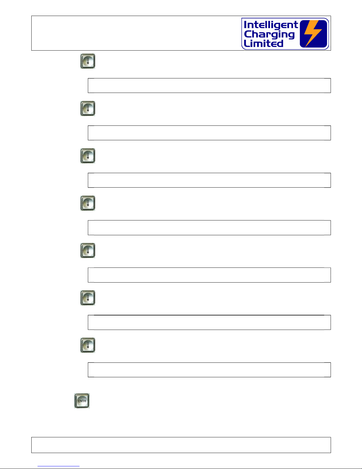
Using the up and down arrow keys on the keypad the alternative TS1340+ functions can
be accessed. The function displays are as follows:
Press
T S 1 3 4 0 + M A I N M E N U 7 - 0 5 - 2 0 0 1 1 6 : 3 0 : 1 5
P R E V I E W R E S U L T S O F L A S T C H A R G E O R T E S T
Doc: DWG1030-25-R11 TS1340+ Operators manual.odt Page 6 of 72 Copyright Material of Intelligent Charging Limited © 2015
Printed On : 12/06/17
NSN 6130-99-391-3441 (TS1340+)
Battery Charger Analyser : Operator Manual
Press
T S 1 3 4 0 + M A I N M E N U 7 - 0 5 - 2 0 0 1 1 6 : 3 0 : 1 5
P R I N T R E S U L T S O F L A S T C H A R G E O R T E S T
Press
T S 1 3 4 0 + M A I N M E N U 7 - 0 5 - 2 0 0 1 1 6 : 3 0 : 1 5
M O D I F Y C U R R E N T T I M E O F D A Y A N D D A T E
Press
T S 1 3 4 0 + M A I N M E N U 7 - 0 5 - 2 0 0 1 1 6 : 3 0 : 1 5
C R E A T E O R M O D I F Y C U S T O M L I B R A R Y E N T R Y
Press
T S 1 3 4 0 + M A I N M E N U 7 - 0 5 - 2 0 0 1 1 6 : 3 0 : 1 5
S E N D I N T E R N A L L I B R A R Y T O P R I N T E R
Press
T S 1 3 4 0 + M A I N M E N U 7 - 0 5 - 2 0 0 1 1 6 : 3 0 : 1 5
C A L I B R A T E T S 1 3 4 0 + V O L T A G E A N D C U R R E N T
Press
T S 1 3 4 0 + M A I N M E N U 7 - 0 5 - 2 0 0 1 1 6 : 3 0 : 1 5
P E R F O R M E L E C T R I C A L T E S T S
Press and the functions are repeated
T S 1 3 4 0 + M A I N M E N U 7 - 0 5 - 2 0 0 1 1 6 : 3 0 : 1 5
P E R F O R M C H A R G E / T E S T U S I N G N S N N U M B E R
The desired function is selected as shown above and subsequently accessed by pressing
the key.
Doc: DWG1030-25-R11 TS1340+ Operators manual.odt Page 7 of 72 Copyright Material of Intelligent Charging Limited © 2015
Printed On : 12/06/17
NSN 6130-99-391-3441 (TS1340+)
Battery Charger Analyser : Operator Manual
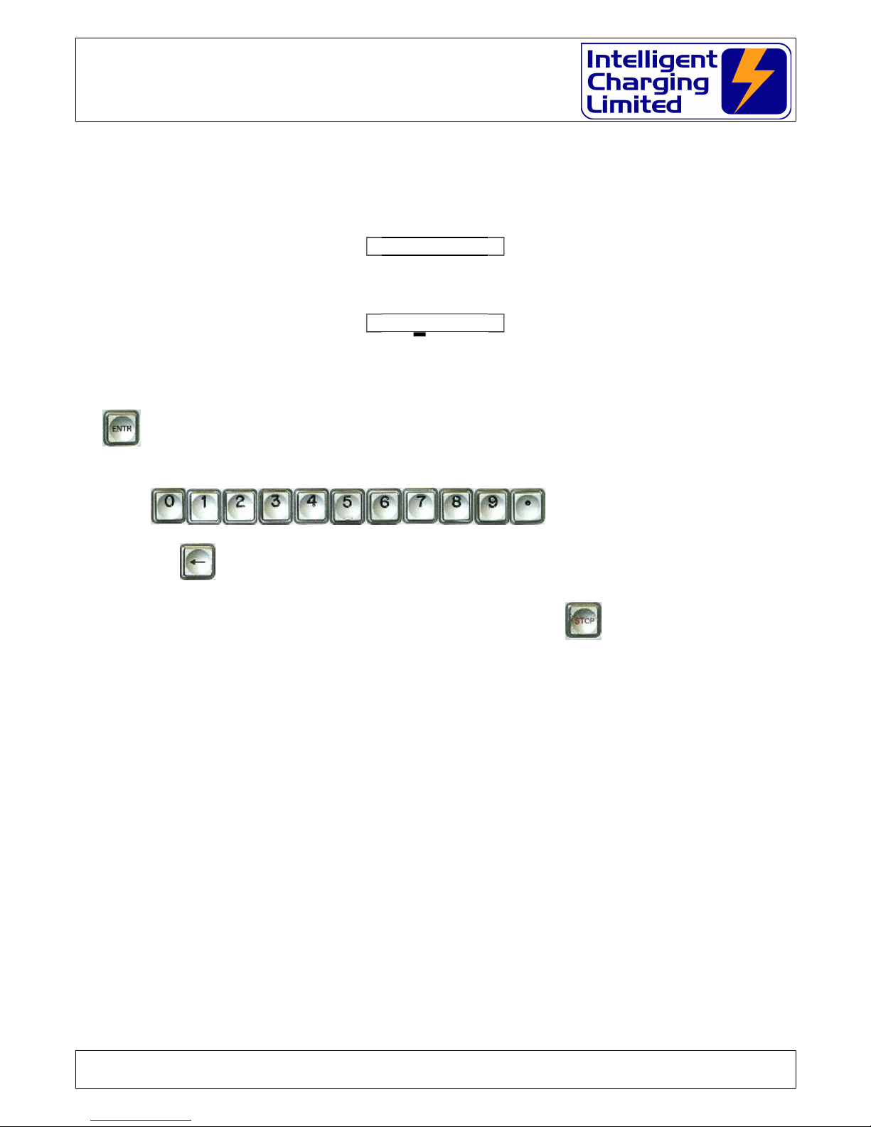
3.3 Numeric Data Input
Most charger operations only require the input of either field data denoted by the down arrow key
shown next to the modifiable data thus:
P b
or the use of numeric data shown by preloaded numeric values and a flashing cursor thus:
0 . V
For field data input repeated use of the down arrow key would cycle through all the available
permutations for the particular example. Once the desired value is found this is selected by pressing
the key.
For numeric data input the use of the
keys will insert corresponding numbers and decimal point as appropriate. The back arrow
key will erase the previously entered number allowing for corrections.
At any time with any data entry or menu selections the key will abort whatever is
being done and revert back to the charger default screen.
4 Connecting A Battery
Provided with the TS1340+ is one set of leads terminated with 8mm Ring Crimp Connectors.
These leads are specially made and have a separate sense wires running in parallel with each of
the heavy current charge/discharge wires. The 8mm ring crimps should be fitted with suitable
battery connectors to suit the battery being charged.
Always connect the battery leads to the TS1340+ before attempting to connect the battery to be
charged/tested. All four leads must be connected to the TS1340+. The heavy welding style
connectors first and then the appropriate sense wires. Black plug to Black Socket and Red plug to
Red socket.
Doc: DWG1030-25-R11 TS1340+ Operators manual.odt Page 8 of 72 Copyright Material of Intelligent Charging Limited © 2015
Printed On : 12/06/17

NSN 6130-99-391-3441 (TS1340+)
Battery Charger Analyser : Operator Manual
Once the charger leads are connected to the TS1340+ then the battery can be connected.
STANDARD LEAD SET SUPPLIED WITH EQUIPMENT
Specialist lead sets are available by request to suit many battery types. Please contact
Intelligent Charging for prices and availability.
Doc: DWG1030-25-R11 TS1340+ Operators manual.odt Page 9 of 72 Copyright Material of Intelligent Charging Limited © 2015
Printed On : 12/06/17
POWER CABLE : 25mm SQR BUTYL INSULATED WELDING CABLE (ELAND)
SENSE CABLE : TEST LEAD CABLE RED & BLACK CSP 55/0.15mm
8mm CRIMP CONNECTOR
BOTH CABLES JOINED AND
CRIMPED INTO SOCKET
BLACK HEATSHRINK AT CRIMP END FOR 150mm +/- 5mm
RED HEATSHRINK AT CRIMP END FOR 150mm +/- 5mm
POSITIVE SOCKET (DINSE DIX BKM 25)
1500mm ± 50mm
4mm SHROUDED PLUG BLACK
4mm SHROUDED PLUG RED
NEGATIVE PLUG (DINSE DIX SKM 25)
HEATSHRINK 100mm AT 100mm INTERVALS
RED HEATSHRINK 100mm AT 100mm INTERVALS
CJF
GC
16-10-2004
DWG1030-1111 1
SEE DRAWING NA
NA
TS1340+ STANDARD LEAD SET
First Drawn.
.
.
.
.
.
.
.
.
. .
. .
.
.
.
.
.
.
.
.
.
.
.
.
.
.
..±
NOT SCALED
UNCLASSIFIED
SECURITY CLASSIFICATION
Drawing No SHEET
TITLE
CasC Systems Ltd.
Ford House, Dewing Road
Rackheath Industrial Estate
Norwich, Norfolk
NR13 6PS
TEL +44-(0)1603-722770 FAX +44-(0)1603-722771
EMAIL sales@casc-ltd.com
CHECKED
DRAWN
MATERIAL
SCALE
UNITS
TOLERANCE
FINISH
CHANGE DESCRIPTION DATEISS
OF
COLOUR
METRIC
THIRD ANGLE
PROJECTION
CHANGE DESCRIPTION DATEISS

NSN 6130-99-391-3441 (TS1340+)
Battery Charger Analyser : Operator Manual
5 Battery Discharge Operation
The modes of operation are the same for both lead acid and alkaline batteries, so discharge
parameters entered are the same for both types. Therefore the references in this section will be
made to refer to either type.
5.1 Parameters Required
The TS1340+ requires three basic parameters to be entered for this function.
a) Test Trip Voltage.
The test trip voltage is important and must be entered on custom library data
because the TS1340+ uses this to define the point at which the battery has reached
it's set discharged point
b) Test discharge current.
During the period of discharge the TS1340+ will regulate the current drawn from the
battery at this level, regardless of terminal voltage.
c) Test time.
The maximum time that the test must perform, before being terminated.
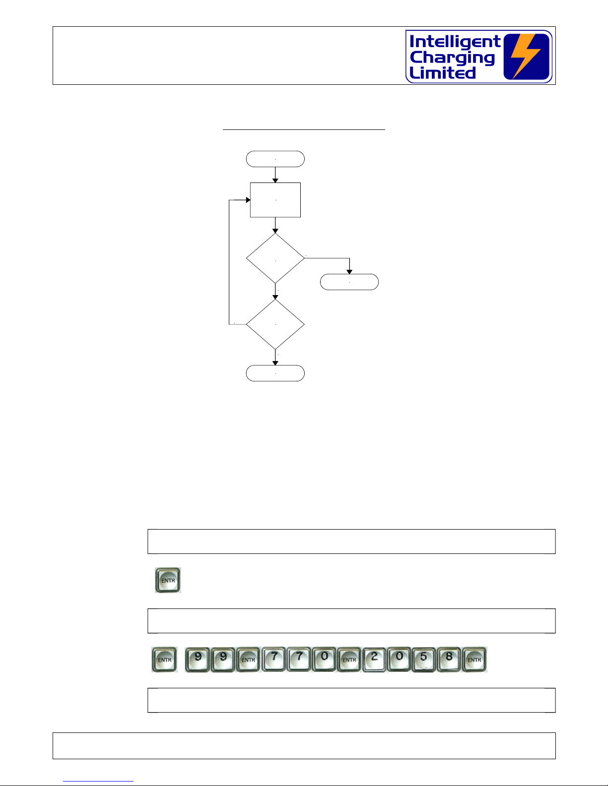
5.2 Test Operation
The test is performed by discharging the battery by the current set in (b), for a maximum
time set in (c).
If a battery achieves this target it is considered to be 100% or more efficient.
If the battery terminal voltage falls to (a), then the TS1340+ will terminate the process
and report the capacity as a percentage of elapsed time.
It is important that when entering custom library entries that the manufacturers
recommendations are referred to for capacity test parameters.
As a general guide it is usual to have typically the ampere/hour rating of the battery as the
discharge current and the time set to one hour. The termination voltage us set to typically
20V for a 24V battery.
Example:
For a 24V 44A/H battery the following parameters would set.
Trip Voltage 20 Volt
Discharge Current 44 Ampere
Time 1 Hour
If the battery under test fails with by falling to the trip voltage after 55 minutes then it's
Doc: DWG1030-25-R11 TS1340+ Operators manual.odt Page 10 of 72 Copyright Material of Intelligent Charging Limited © 2015
Printed On : 12/06/17
NSN 6130-99-391-3441 (TS1340+)
Battery Charger Analyser : Operator Manual
capacity will be reported as 91.6%. Calculated thus: - (55m / 60m * 100%) =91.6%
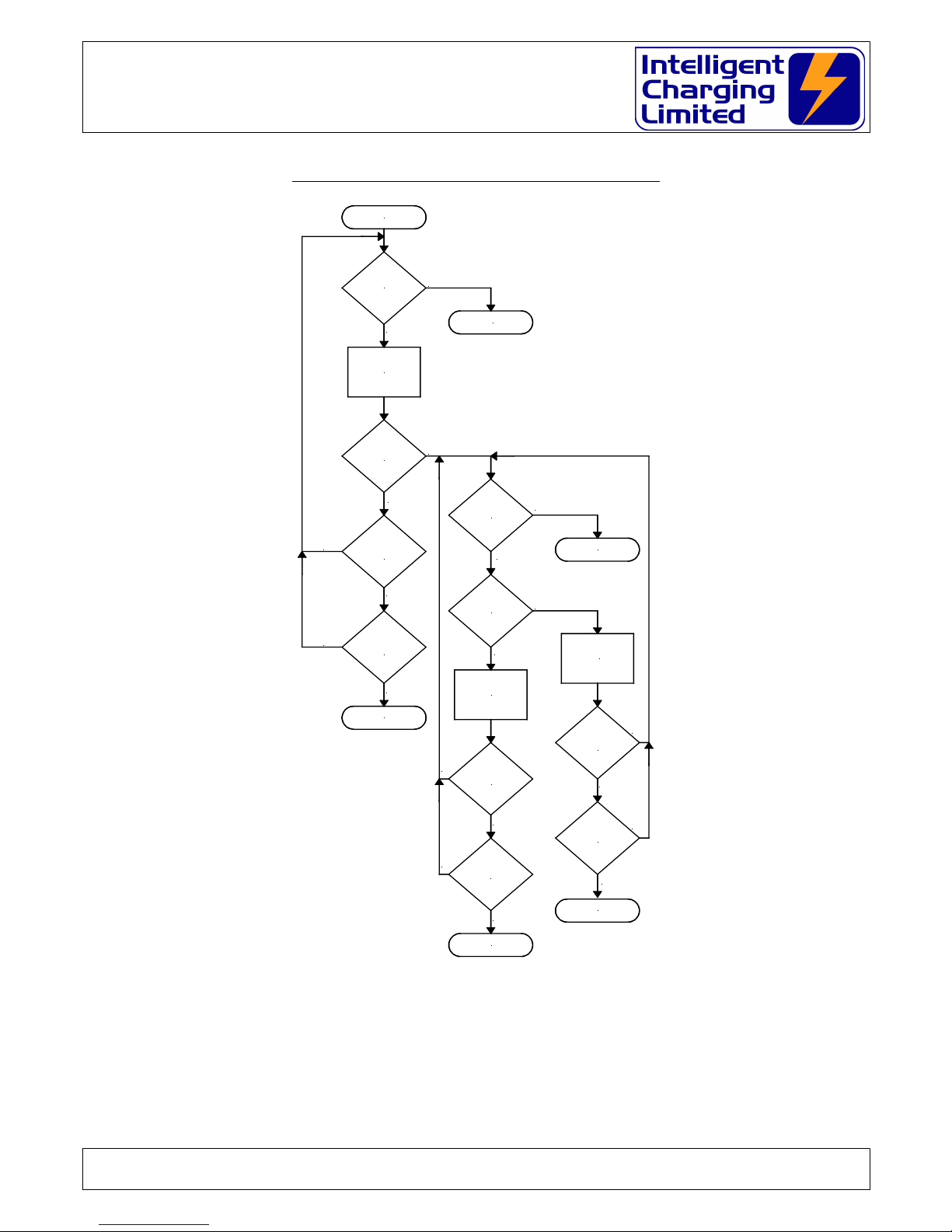
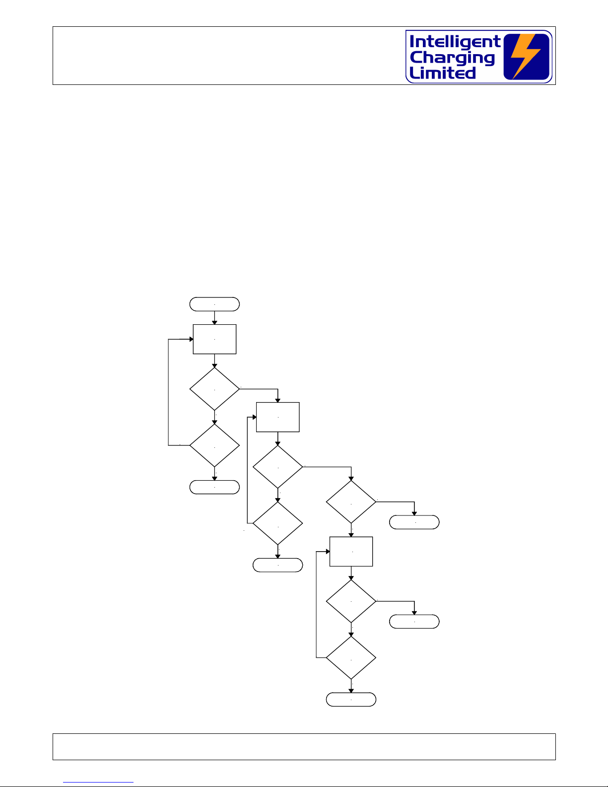
CAPACITY TEST PROCESS FLOW
START
MAINTAIN
TEST
CURRENT
MINIMUM
VOLTAGE
REACHED
?
END
% >= 100
NO
TIME
EXPIRED
?
END
%=TP/TS*100
YES
NO
YES
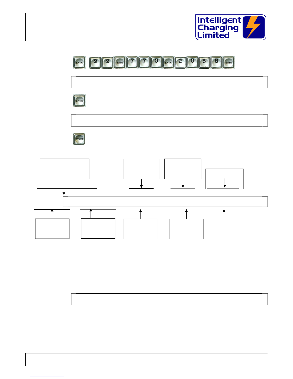
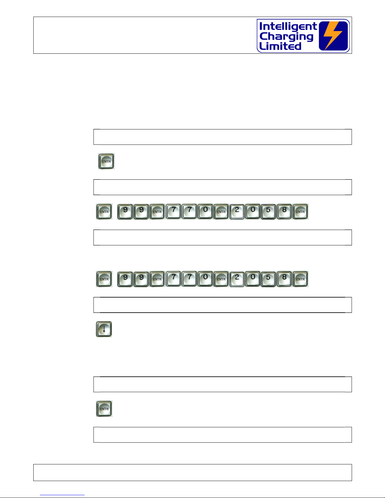
5.3 Starting A Capacity Test
Follow the following instructions for performing a capacity test on a NSN listed battery. In
this example we use battery NSN 6140-99-770-2058 as an example. Please substitute the
correct battery NSN where appropriate.
Connect battery.
Apply power to the TS1340+
T S 1 3 4 0 + M A I N M E N U 7 - 0 5 - 2 0 0 1 1 6 : 3 0 : 1 5
P E R F O R M C H A R G E / T E S T U S I N G N S N N U M B E R
Press
E N T E R B A T T E R Y N U M B E R
N S N 6 1 4 0 - - -
Press
H A W K E R 9 7 5 0 - 0 7 4 1 R E F E R : A P 1 1 3 C - 0 0 0 1 - 1
N S N 6 1 4 0 - - - R E - E N T E R T O C O N F I R M
Doc: DWG1030-25-R11 TS1340+ Operators manual.odt Page 11 of 72 Copyright Material of Intelligent Charging Limited © 2015
Printed On : 12/06/17
NSN 6130-99-391-3441 (TS1340+)
Battery Charger Analyser : Operator Manual
Verify that the correct battery has been selected.
Press
S E L E C T P R O C E S S R E Q U I R E D F O R T H I S B A T T E R Y
C A P A C I T Y T E S T
Press
S T A R T C A P T E S T
E N D V O L T S 2 0 . 0 V A M P S 1 8 . 0 A T I M E 1 . 0 H
Press
The TS1340+ display will show the basic test parameters, the type of test and the
present valid voltage and current and time elapsed. This display will be shown as follows:
C A P A C I T Y T E S T 2 0 . 0 0 V 1 8 . 0 0 A 1 . 0 0 H
R U N
0 . 0 % 0 . 0 0 V 0 . 0 0 A 0 . 0 0 H
5.4 Capacity Test Termination
Following the end of test, the TS1340+ will sound the audible alarm until any key on the
key panel is pressed. The display will show the capacity test values until another key is
pressed, at which time if a printer is connected will print the test results. The display will
then resume the normal default mode as follows:
T S 1 3 4 0 + M A I N M E N U 7 - 0 5 - 2 0 0 1 1 6 : 3 0 : 1 5
P E R F O R M C H A R G E / T E S T U S I N G N S N N U M B E R
Doc: DWG1030-25-R11 TS1340+ Operators manual.odt Page 12 of 72 Copyright Material of Intelligent Charging Limited © 2015
Printed On : 12/06/17
TYPE OF TEST BEING
PERFORMED
PRESET TRIP
VOLTAGE
PRESET TEST
CURRENT
PRESET TEST
DURATION
ACTIVE RUN
INDICATOR
CAPACITY SO
FAR
BATTERY
VOLTAGE
BATTERY
CURRENT
TIME ELAPSED

NSN 6130-99-391-3441 (TS1340+)
Battery Charger Analyser : Operator Manual
6 Battery Charge Operation
6.1 Lead Acid Constant Voltage Charge
6.1.1 Parameters Required
a) Target constant voltage.
This is the constant voltage target value that the charger will maintain during
the charge cycle.
b) Maximum charge current.
This value of current is the maximum current that he charger will charge the
battery at before it achieves it's constant voltage mode.
c) Duration of complete charge.
This time is the maximum time that the charger is to charge the battery before
termination.
d) Minimum charge current.
Sets the value of current that when reached terminates the charge process.
This value is optional and should be set to zero if not required.
e) Current threshold.
This sets a safety point that once the charger has reached it's maximum
current: the current would normally fall. If the charge current then proceeds to
rise to a value greater than this setting then the charge process is terminates,
indicating that there is a potential problem with the battery.
This value is optional and should be set to zero if not required.
f) Current to potential changeover time.
If the target voltage has not been reached within this time then the charge
process is terminated indicating a battery fault.
This value is optional and should be set to zero if not required.
Doc: DWG1030-25-R11 TS1340+ Operators manual.odt Page 13 of 72 Copyright Material of Intelligent Charging Limited © 2015
Printed On : 12/06/17

NSN 6130-99-391-3441 (TS1340+)
Battery Charger Analyser : Operator Manual
6.1.2 Charge Operation
The charge process consists of charging the battery at the maximum current (b) until
the battery voltage (a) is met. Upon this time it will maintain the battery terminal
voltage (a) by regulating the charge current, until either of the following parameters
are met.
The maximum charge time elapsed (c).
Optionally the charge current drops below the minimum charge
threshold (d).
Optionally the falling charge current rising to a value greater than the
current threshold (e).
Optionally the charger unable to reach the target battery voltage
with the preset time (f).
Doc: DWG1030-25-R11 TS1340+ Operators manual.odt Page 14 of 72 Copyright Material of Intelligent Charging Limited © 2015
Printed On : 12/06/17
NSN 6130-99-391-3441 (TS1340+)
Battery Charger Analyser : Operator Manual
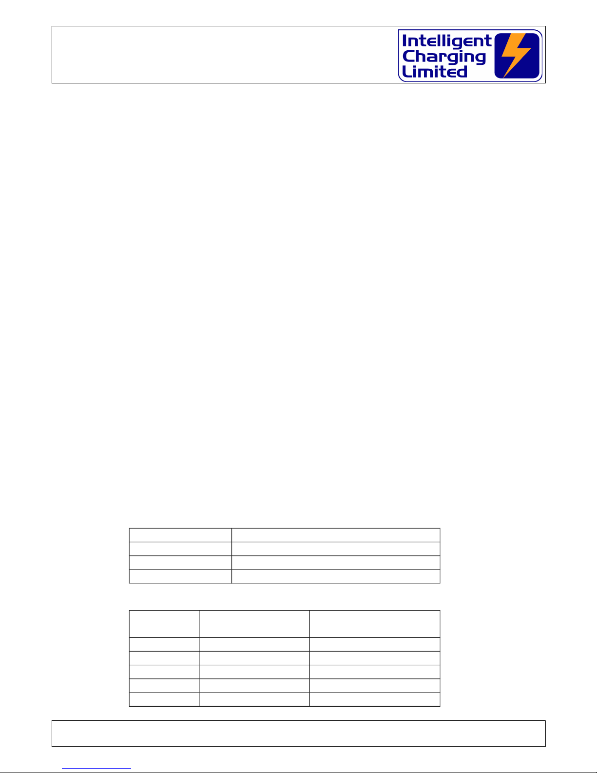
CONSTANT VOLTAGE CHARGE PROCESS FLOW
START
TIME
EXPIRED
?
MAINTAIN
MAXIMUM
CURRENT
END
CHOVER EXP
NO
TARGET
VOLTAGE
REACHED
?
END
MIN AMPS
YES
NO
YES
END
COMPLETE
END
COMPLETE
C/V CHOVER
SET
?
C/V CHOVER
EXPIRED
?
TIME
EXPIRED
?
BATT V
>
SET VOLTS
?
INCREASE
CHARGE
CURRENT
MIN AMPS
SET
?
CHARGE
AMPS <
MIN AMPS
?
REDUCE
CHARGE
CURRENT
THRESHOLD
SET
?
YES
NO
YES
NO
NO
YES
NO
YES
NO
YES
NO
YES
YES
NO
INCREASE
>
THRESHOLD
?
END
THRESHOLD
YES
NO
Doc: DWG1030-25-R11 TS1340+ Operators manual.odt Page 15 of 72 Copyright Material of Intelligent Charging Limited © 2015
Printed On : 12/06/17
NSN 6130-99-391-3441 (TS1340+)
Battery Charger Analyser : Operator Manual
6.2 Lead Acid Constant Current Charge
6.2.1 Parameters Required
a) Battery Nominal Voltage.
This is the normal nominal voltage of the battery to be charged.
b) Battery charge current.
This is constant current required to charge the battery.
c) Battery overcharge voltage.
This is the overcharge voltage of the battery.
6.2.2 Charge Operation
At the start of charge the charger will monitor the open circuit voltage of the battery
before starting. It will use this value to calculate the approximate duration of the
constant current charge.
This is based on the following algorithm: -
DURATION = -(OCV-(NOMINAL+(NOMINAL * 0.075)))*(199.2 / NOMINAL)
Where:
DURATION: LENGTH OF CHARGE IN HOURS
OCV: BATTERY OPEN CIRCUIT VOLTAGE
NOMINAL:BATTERY NOMINAL VOLTAGE
This algorithm has been derived from the specifics of MINISTRY OF DEFENCE AIRCRAFT BATTERIES GENERAL AND TECHNICAL INFORMATION AP113c-0001-1 3rd
edition.
The following table illustrates the source of data that was used to derive the
algorithm.
Typical charge rates are:
Battery Capacity Constant Current Charge Rate
40AH 3.0A
25AH 2.0A
18AH 1.4A
Typical Charge Times would be:
Battery OCV Approximate
Capacity
Charge Time Hours
25.8V 100% 0H
25.5V 80% 3H
25.2V 65% 5.5H
24.8V 50% 8H
24.6V 40% 9.5H
Doc: DWG1030-25-R11 TS1340+ Operators manual.odt Page 16 of 72 Copyright Material of Intelligent Charging Limited © 2015
Printed On : 12/06/17

NSN 6130-99-391-3441 (TS1340+)
Battery Charger Analyser : Operator Manual
Battery OCV Approximate
Capacity
Charge Time Hours
24.2V 20% 13H
24.0V 10% 14.2H
<23.8V 0% 16H
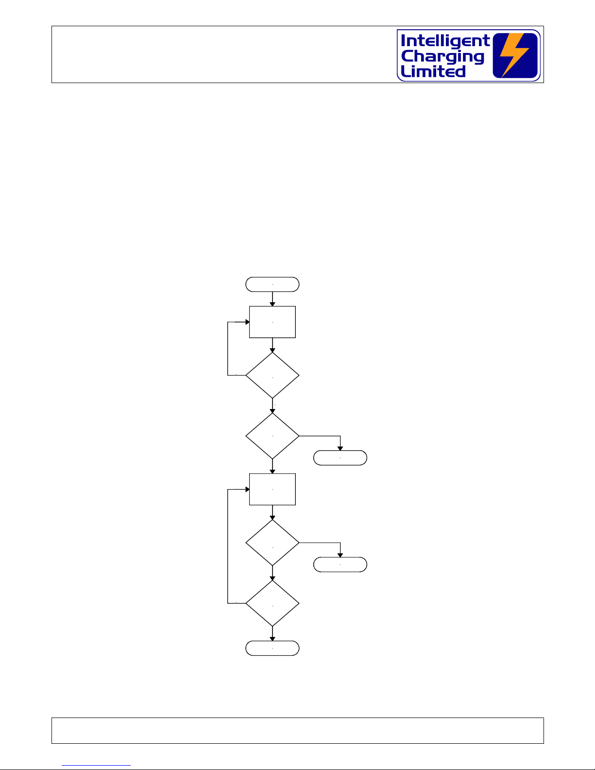
CONSTANT CURRENT CHARGE PROCESS FLOW
START
READ BATTERY
OPEN CIRCUIT
VOLTAGE
END
OVERVOLT
OVERVOLT
REACHED
?
NO
YES
END
COMPLETE
TIME
COMPLETED
?
MAINTAIN
CHARGE
CURRENT
CALCULATE
CHARGE
DURATION
NO
YES
Doc: DWG1030-25-R11 TS1340+ Operators manual.odt Page 17 of 72 Copyright Material of Intelligent Charging Limited © 2015
Printed On : 12/06/17

NSN 6130-99-391-3441 (TS1340+)
Battery Charger Analyser : Operator Manual
6.3 Alkaline 0.1c & 0.2c Charge
6.3.1 Parameters Required
a) Overcharge Voltage
This voltage is the setting, which defines when the battery has reached an
overcharged state.
b) Target Voltage
This voltage is the charge voltage aimed for.
c) Charge Current
This is usually one tenth for 0.1C or one fifth for 0.2C of the battery capacity,
i.e. for a 44A/H battery this would be set to 4.4A or 8.8A respectively
d) Additional Charge Time
This time defines the additional charge time upon the target voltage being
achieved.
Doc: DWG1030-25-R11 TS1340+ Operators manual.odt Page 18 of 72 Copyright Material of Intelligent Charging Limited © 2015
Printed On : 12/06/17
NSN 6130-99-391-3441 (TS1340+)
Battery Charger Analyser : Operator Manual
6.3.2 Charge Operation
The TS1340+ will charge the battery at the current defined in (c) until the
target voltage (b) is reached, at which time it will then continue to charge the
battery at the current (c) until the additional time (d) has passed at which time
the charge will stop. If during the additional time (d) the battery terminal
voltage reached the overcharge voltage (a) then the charge will stop.
Note if the target voltage is not attained within 24 Hours the charger will stop
the process with a "time greater than 24H" warning.
0.1C & 0.2C PROCESS FLOW
Doc: DWG1030-25-R11 TS1340+ Operators manual.odt Page 19 of 72 Copyright Material of Intelligent Charging Limited © 2015
Printed On : 12/06/17
START
MAINTAIN
CHARGE
CURRENT
TARGET
VOLTAGE
REACHED
?
ADDITIONAL
TIME EXPIRED
?
MAINTAIN
CHARGE
CURRENT
EXCEEDED
OVERCHARGE
VOLTAGE
?
END
COMPLETE
NO
YES
TIME > 24H
NO
END
OVERVOLTAGE
END
T > 24H

NSN 6130-99-391-3441 (TS1340+)
Battery Charger Analyser : Operator Manual
6.4 Alkaline Two And Three Step Charge
6.4.1 Parameters Required
a) Step charge current
This consists of one two or three charge current values.
b) Step charge duration
For each step a value of time for the duration of the charge must be set.
c) Battery Overcharge Voltage
This voltage is the setting, which defines when the battery has reached an
overcharged state.
Doc: DWG1030-25-R11 TS1340+ Operators manual.odt Page 20 of 72 Copyright Material of Intelligent Charging Limited © 2015
Printed On : 12/06/17
NSN 6130-99-391-3441 (TS1340+)
Battery Charger Analyser : Operator Manual
6.4.2 Charge Operation
In this mode the charger will start the charge at the step one current (a) for the
duration of charge (b). Once the duration for this step has expired it will switch
to step two and charge at the step two current for the duration specified. Once
this step has expired it will then switch to step three and perform the charge
using the step three parameters. During all steps of the charge it will monitor
the battery terminal voltage and stop the charge if this is exceeded.
If no current is specified during any one of the steps but a valid duration the
charge will effectively rest for that duration. This is a useful feature where using
three-step charge the middle step can "rest" the battery before completing the
final charge.
TWO AND THREE STEP PROCESS FLOW
START
MAINTAIN
STEP #1
CURRENT
END
OVERVOLT NO
OVERVOLT
REACHED
?
END
OVERVOLT
YES
NO
YES
THREE STEP
COMPLETE
TWO STEP
COMPLETE
STEP #1
TIME
COMPLETED
?
THREE
STEP
MODE
?
STEP #2
TIME
COMPLETED
?
MAINTAIN
STEP #3
CURRENT
OVERVOLT
REACHED
?
MAINTAIN
STEP #2
CURRENT
STEP #3
TIME
COMPLETED
?
NO
NO
YES
YES
NO
YES
YES
NO
OVERVOLT
REACHED
?
END
OVERVOLT
YES
NO
Doc: DWG1030-25-R11 TS1340+ Operators manual.odt Page 21 of 72 Copyright Material of Intelligent Charging Limited © 2015
Printed On : 12/06/17
NSN 6130-99-391-3441 (TS1340+)
Battery Charger Analyser : Operator Manual
6.5 Charging Lead Acid (Pb) Batteries
Follow the following instructions for performing a charge on a NSN listed battery.
Connect battery.
Apply power to the TS1340+
T S 1 3 4 0 + M A I N M E N U 7 - 0 5 - 2 0 0 1 1 6 : 3 0 : 1 5
P E R F O R M C H A R G E / T E S T U S I N G N S N N U M B E R
Press
E N T E R B A T T E R Y N U M B E R
N S N 6 1 4 0 - - -
Press
H A W K E R 9 7 5 0 - 0 7 4 1 R E F E R : A P 1 1 3 C - 0 0 0 1 - 1
N S N 6 1 4 0 - - - R E - E N T E R T O C O N F I R M
Verify that the correct battery has been selected.
Press
S E L E C T P R O C E S S R E Q U I R E D F O R T H I S B A T T E R Y
C A P A C I T Y T E S T
Press
6.5.1 For Cv Charge
S E L E C T P R O C E S S R E Q U I R E D F O R T H I S B A T T E R Y
C V C H A R G E
Press
S T A R T C V C H A R G E 2 9 . 0 V 2 0 . 0 A H R S 4 . 0 H
M I N A M P S 0 . 2 5 A C H O V E R 1 . 0 H C T H S H 1 . 0 A
Doc: DWG1030-25-R11 TS1340+ Operators manual.odt Page 22 of 72 Copyright Material of Intelligent Charging Limited © 2015
Printed On : 12/06/17
 Loading...