

Intelligent Automation ARGUS User Manual

Protected under U.S. patent number 8,232,878
© 2016 Intelligent Automation, Inc. | 15400 Calhoun Drive, Suite 190, Rockville, MD 20855 | Phone: 301 294 5200 | Fax: 301 294 5201
Revision G October 2016

Page | 1
© 2016 Intelligent Automation, Inc.
Table of Contents
1 FCC Certifications and Regulatory information .................................................................................... 2
2 Quick Start Guide .................................................................................................................................. 3
3 Hardware Overview .............................................................................................................................. 7
3.1 Sensor Node Description .............................................................................................................. 7
4 Software Overview .............................................................................................................................. 10
4.1 Initial Setup Wizard ..................................................................................................................... 10
4.2 User Interface Overview ............................................................................................................. 11
4.2.1 Main Toolbar ....................................................................................................................... 11
4.2.2 GUI Panels ........................................................................................................................... 11
4.3 Configuration Wizard .................................................................................................................. 13
4.4 Configuration and Active Modes ................................................................................................ 14
4.5 Node Positioning ......................................................................................................................... 14
4.5.1 Drag-and-Drop Node Positioning ........................................................................................ 15
4.5.2 Manual Lat/Long Node Positioning ..................................................................................... 15
4.5.3 GPS Node Positioning .......................................................................................................... 15
4.6 Link Configuration ....................................................................................................................... 16
4.6.1 Link Configuration Window ................................................................................................ 16
4.6.2 Link Configuration Toolbar .................................................................................................. 17
4.7 Link Metrics Mode ...................................................................................................................... 19
4.7.1 Link Metrics Guidelines ....................................................................................................... 20
4.8 Alerts ........................................................................................................................................... 20
4.8.1 Alert Log Files ...................................................................................................................... 21
4.9 Plug-in Configuration .................................................................................................................. 21
4.9.1 Camera Plug-in .................................................................................................................... 21
4.9.2 Text Message Plug-in .......................................................................................................... 23
5 System Shutdown ............................................................................................................................... 25
6 Node Deployment Guide .................................................................................................................... 26
7 Troubleshooting .................................................................................................................................. 28

Page | 2
© 2016 Intelligent Automation, Inc.
1 FCC Certifications and Regulatory information
FCC Part 15 Class B
Radio Frequency Interface (RFI) (FCC 15.105)
This device has been tested and found to comply with the limits for Class B digital devices pursuant to
Part 15 Subpart B, of the FCC rules. These limits are designed to provide reasonable protection against
harmful interference in a residential environment. This equipment generates, uses, and can radiate
radio frequency energy, and if not installed and used in accordance with the instruction manual, may
cause harmful interference to radio communications. However, there is no guarantee that interference
will not occur in a particular installation. If this equipment does cause harmful interference to radio or
television reception, which can be determined by turning the equipment off and on, the user is
encouraged to try and correct the interference by one or more of the following measures:
Reorient or relocate the receiving antenna.
Increase the separation between the equipment and receiver.
Connect the equipment into an outlet on a circuit different from that to which the receiver is
connected.
Consult the dealer or an experienced radio/TV technician for help.
Labeling Requirements (FCC 15.19)
This device complies with Part 15 of FCC rules. Operation is subject to the following two conditions: (1)
this device may not cause harmful interference, and (2) this device must accept any interference
received, including interference that may cause undesired operation.
Modifications (FCC 15.21)
Changes or modifications to this equipment not expressly approved by Intelligent Automation, Inc. may
void the user’s authority to operate this equipment.
FCC Radiation Exposure Statement
This equipment complies with FCC radiation exposure limits set forth for an uncontrolled environment.
To satisfy FCC RF exposure requirements for mobile transmitting devices, a separation distance of 20 cm
or more should be maintained between the antenna of this device and persons during device operation.
To ensure compliance, operations at closer than this distance are not recommended.

Page | 3
© 2016 Intelligent Automation, Inc.
2 Quick Start Guide
This Quick Start section of the user manual presents the basics of getting an ARGUS deployment up and
running. For more details on each topic, refer to the later sections in this manual.
Step 1: Turn on the laptop PC
Note that if the laptop is locked, the default username is ‘argus’ and the password is ‘iai’
Step 2: Connect the Gateway node and turn it on
The ‘Gateway Node’ enables communication between the ARGUS nodes and the laptop PC. The
Gateway node connects to the PC via a short USB cable, and uses a 2.4GHz antenna with a standard RPTNC connector) to communicate with the ARGUS network.
- Attach an antenna to the port on the top of the Gateway node.
- Connect the included USB cable to the rugged connector on Gateway Node and plug the other
end into one of the USB ports on the right side of the laptop (see Figure 1). Be sure to use the
same USB port each time you connect the Gateway Node, as the software is configured to look
for it on the same port each time. The gateway will power on as soon as it is connected to the
USB port.
- Attach the external 2.4GHz antenna to the Gateway Node. Optional: Connect an RF extension
cable and outdoor rated antenna to position the antenna outside of a building or on a rooftop.
For antenna coax cable runs greater than 10ft, use an RF amplifier (contact IAI for details).
Figure 1: ARGUS Gateway connection to PC
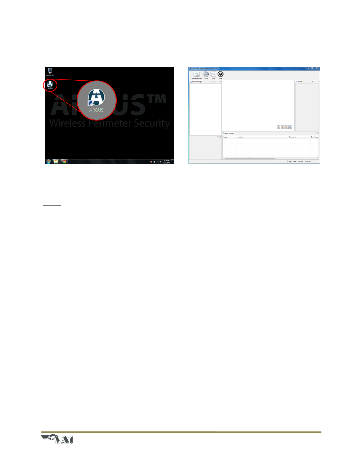
Step 3: Start the ARGUS software
To start the ARGUS software, click the ‘ARGUS’ software icon on the desktop (see Figure 2). The splash
screen for the ARGUS View application should appear, then after a few seconds, the main graphical user
Page | 4
© 2016 Intelligent Automation, Inc.
interface (GUI) should appear. For a full description of the GUI, modes, buttons, etc. see Section Error! R
eference source not found..
Figure 2: Starting the ARGUS software. Click the 'ARGUS' icon (left) to start the GUI software (right)
Step 4: Create a new ARGUS configuration
Prior to operating the ARGUS system, it must be configured by defining the node locations and active
fence links to monitor.
- Press the ‘Configure’ button in the upper left corner of the screen.
- Select ‘New’ as the Configuration Type and click ‘Next’.
- Specify a configuration description (optional) and select a Map Type: None, Satellite, or User
Defined (see Section 4.3 for descriptions). Click ‘Next’.
- Click ‘Next’ to leave Camera Monitoring disabled (see Section 4.9.1 for details).
- Click ‘Finish’ to leave SMS/MMS Notifications disabled (see Section 4.9.2 for details).
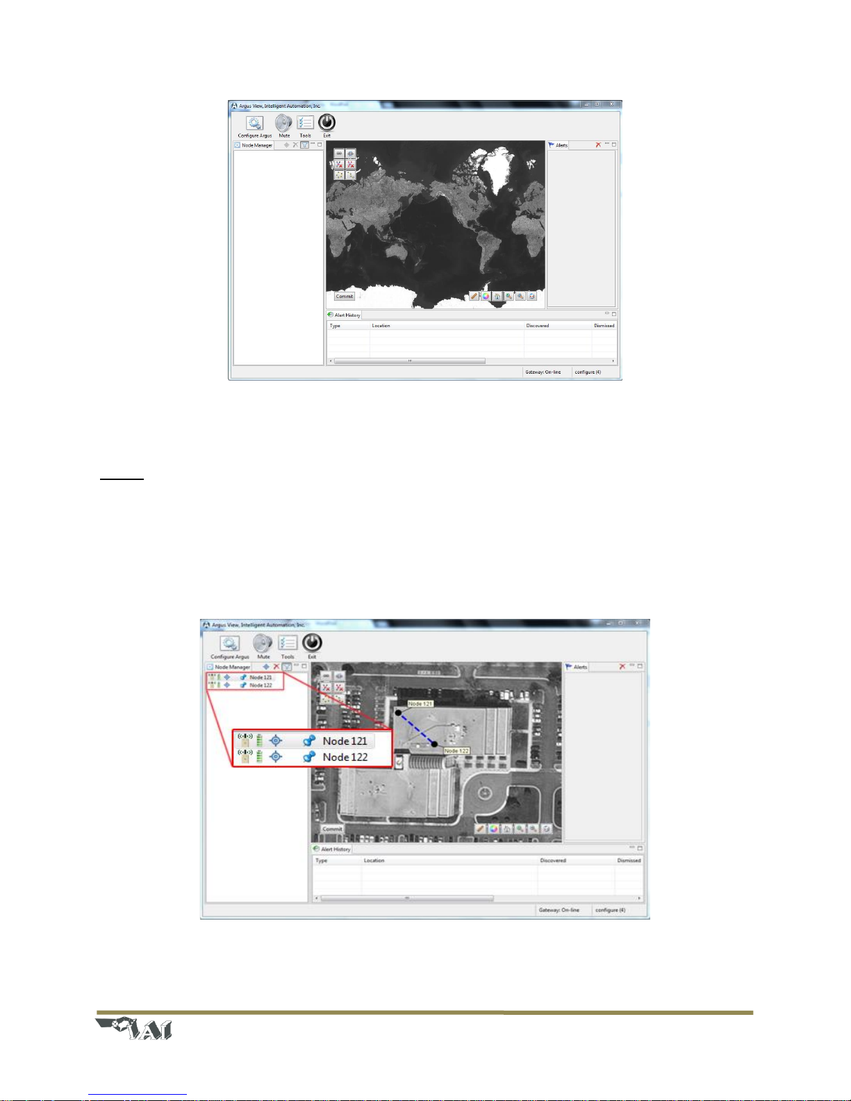
- The new configuration has been created, and you are now in Configuration Mode. The main GUI
should again be displayed (see Figure 3).
Page | 5
© 2016 Intelligent Automation, Inc.
Figure 3: Initial Configuration Mode view (with satellite map type selected)
Step 5: Turn on fence nodes
Attach antennas to and turn on at least two ARGUS fence nodes. They will automatically register with
the system and appear in the ‘Node Manager’ list on the left side of the screen. The nodes will appear
on the screen with the identification number corresponding to the node ID number on the back of each
ARGUS unit. See Section 4.2.2 for detailed descriptions of the icons that are shown in the Node
Manager.
Figure 4: Configuration Mode with two ARGUS nodes turned on

Page | 6
© 2016 Intelligent Automation, Inc.
Step 6: Position nodes on the on-screen map
Pan and zoom to the desired area of the on-screen map. Drag the nodes from the Node Manager list
directly onto the map or click-and-drag the nodes around on the map as desired. See Section 4.5 for full
details regarding placement on nodes on the map.
Step 7: Enable fence links
Click on a link to display the link details window, in which you may specify a link description (optional)
and set the link as either ‘Active’ (actively monitored by the software) or ‘Inactive’ (ignored by the
monitoring software). Active links are indicated in the Map View by solid yellow lines and Inactive links
are indicated by dotted blue lines. See Figure 5 for an example configuration with three nodes, one
active link, and two inactive links. See Section 4.6 for full details regarding link configuration.
Figure 5: Map view of three node configuration with one Active link (yellow line) and two Inactive links (blue dotted lines)
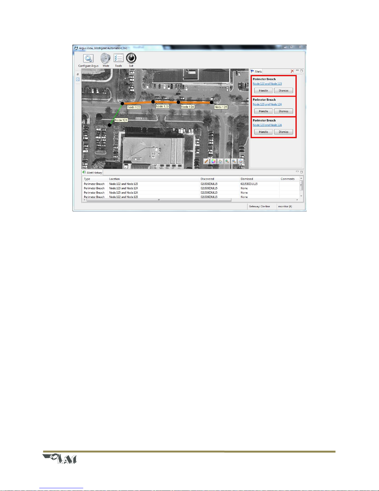
Step 8: ‘Commit’ the configuration
Press the ‘Commit’ button in the lower left corner of the Map View to save the ARGUS configuration and
place the system into Active Mode. The system will now be continuously monitoring and logging any
fence link triggers, displaying alerts both within the Map View and in the Alerts panel on the right side of
the GUI. See sample screenshot in Figure 6, and refer to Section 4.8 for more details regarding the
alerts.
Page | 7
© 2016 Intelligent Automation, Inc.
Figure 6: ARGUS GUI in Active Mode. Alerts are shown in the right panel; Alert History is shown in the bottom panel, and
current status is shown in the center Map View.
3 Hardware Overview
3.1 Sensor Node Description
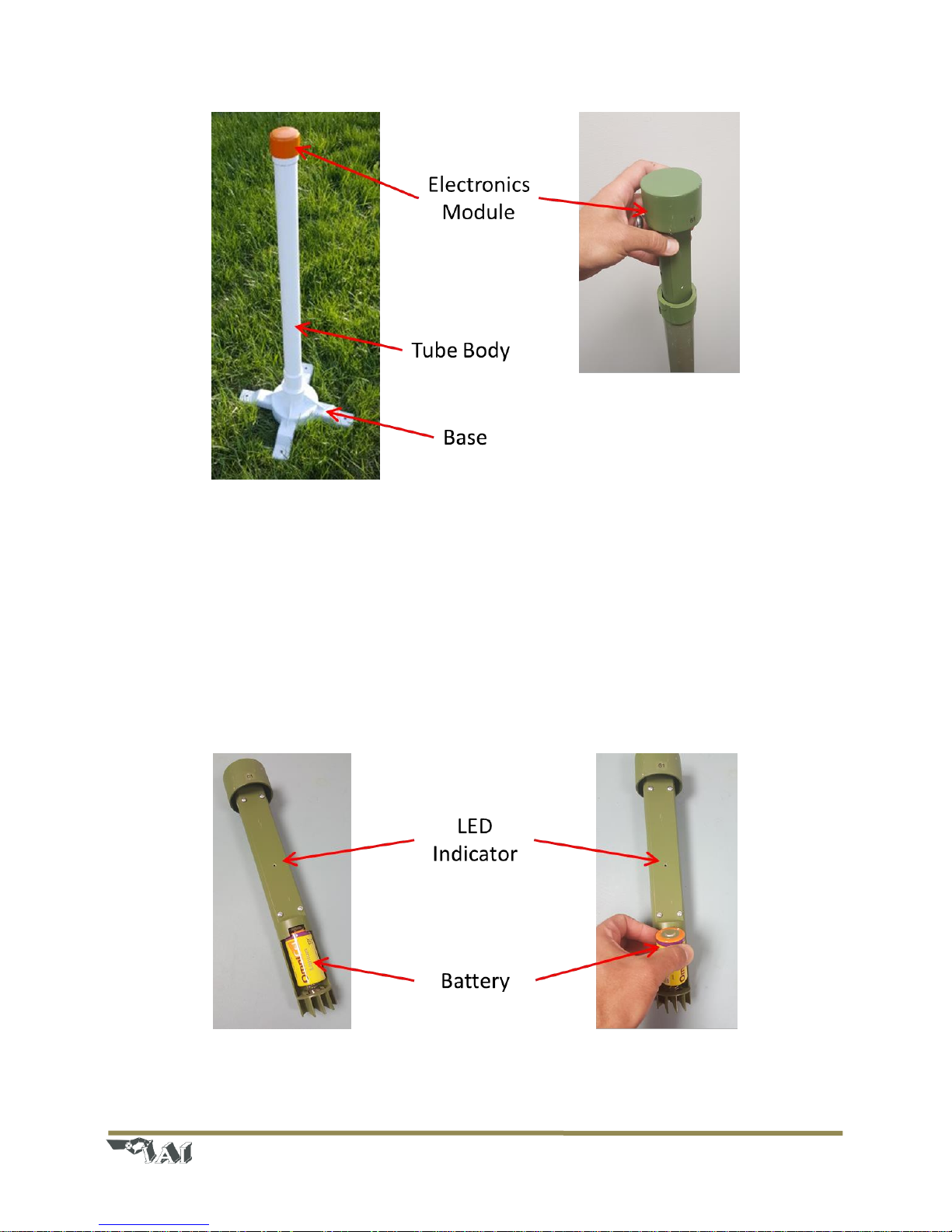
Each ARGUS sensor node is physically contained within a rigid fiberglass tube with a robust plastic base.
The sensor itself is contained within an electronics module that sits inside the top of the fiberglass tube
body. The base can free stand on flat ground, it can be anchored into the ground using 3/8” spikes, or it
can be weighted down using a traffic cone weight or other suitable weight.
Page | 8
© 2016 Intelligent Automation, Inc.
Figure 7: ARGUS Node (left). Close-up of electronics module removal (right).
The top portion of the ARGUS sensor node includes the Electronics Module (see Figure 7 and Figure 8).
The Electronics Module is removed from the pole via a simple twist-lock mechanism. The Electronics
Module is comprised of the ARGUS sensor PCB (housed within the module) and a single D-cell Lithium
battery. Then the battery is installed, the ARGUS sensor PCB will automatically start up and attempt to
join the sensor network. The LED indicator will blink green three times to indicate that the ARGUS
sensor node has powered on. If this indication is not seen, check the battery state and battery
connections.
Figure 8: ARGUS Node electronics module (left) and battery replacement (right).

Page | 9
© 2016 Intelligent Automation, Inc.
The typical runtime for a single fully charged Lithium D-cell battery is approximately 5 months, although
this may vary slightly due to temperature and the specific network configuration of the sensor node. The
ARGUS node has been tested with the OmniCel ER34615 Lithium D-cell battery, which has a nominal
capacity of 19Ah at 3.6V. Other similar Lithium primary cell batteries should also work well.
 Loading...