

Page 1
User Manual
Version 0418
www.intelligent-appliance.com
IA-2660-Ui
Isolated USB port
96 Digital I/O 3.3V/5V
Pluggable Terminal Blocks
Page 2

IA-2660-Ui
2
www.intelligent-appliance.com Specifications are subject to change without notice
Isolated TCP/IP
96 Digital TTL/LVTTL
Pluggable Terminal Blocks
Copyright
Copyright © 1985-2018 Intelligent Appliance Ltd. All rights reserved.
The information in this user manual is subject to change without notice.
Microsoft, Windows and Hyper-Terminal are either registered trademarks or trademarks of
Microsoft Corporation in the United States and/or other countries.
Service & Support
To provide customers with easy to use and 24/7 technical support. Intelligent-Appliance
delivers services via the internet. The dedicated website offers large knowledgebase
database that include full information for Development Engineers, Installers in the field and
for Software Engineers. This KNOWLEDGE BASE Include: Data sheets, User Manuals, FAQ,
Wiring Diagram, Selector Guide and Software section.
Feedback
We at Intelligent-Appliance highly value your opinion. Please feel free to contact us with
your impression on any subject, or with any question or comment you may have.
Contact
Telephone: +972-9-8333-022
Fax: +972-9-8332-965
Support E-mail: support@intelligent-appliance.com
Sales E-mail: sales@intelligent-appliance.com
Website: www.intelligent-appliance.com
.
Page 3

IA-2660-Ui
3
www.intelligent-appliance.com Specifications are subject to change without notice
Isolated TCP/IP
96 Digital TTL/LVTTL
Pluggable Terminal Blocks
INTRODUCTION ............................................................................................................................................... 4
FEATURES .............................................................................................................................................................. 4
SPECIFICATIONS ...................................................................................................................................................... 5
ORDERING INFORMATION ......................................................................................................................................... 5
INSTALLATION ................................................................................................................................................. 7
SYSTEM WIRING ..................................................................................................................................................... 7
Pin Assignment ............................................................................................................................................... 8
Auxiliary Relay Contact Layout ...................................................................................................................... 8
Digital Input / Output Terminal Block ............................................................................................................ 9
............................................................................................................................................................................ 9
INTERNAL CIRCUITS ................................................................................................................................................ 10
SOFTWARE INSTALLATION ....................................................................................................................................... 11
USB Port setup ............................................................................................................................................. 11
Locating the new COM port ......................................................................................................................... 11
IA-3000 Utility .............................................................................................................................................. 12
COMMAND SET.............................................................................................................................................. 14
?AA0 – GET DEVICE NAME ...................................................................................................................................... 15
?AA1 – GET DEVICE FIRMWARE VERSION ................................................................................................................... 16
?AA2 – GET DIGITAL OUTPUT STATUS ....................................................................................................................... 17
?AA3NN – GET BIT STATE ....................................................................................................................................... 19
?AA5 – GET DEVICE MODE (REGISTER #50) ............................................................................................................... 20
?AA51 – GET DEVICE MODE (REGISTER #51) ............................................................................................................. 21
?AAI – GET DIGITAL INPUTS STATUS .......................................................................................................................... 22
?AAID – GET MODULE’S ID NUMBER ........................................................................................................................ 24
?AAPD – GET DEVICE I/O STRUCTURE SETTINGS ......................................................................................................... 25
?AAPU – GET PULL-UPS SETTINGS ........................................................................................................................... 26
?AAS – GET RELAY STATE ....................................................................................................................................... 27
!AA2DDDDDDDDDDDDDDDDDDDDDDDD – SET OUTPUT STATUS ..................................................................................... 28
!AA3DD – ACTIVATE OUTPUT N (00-5F) ................................................................................................................... 29
!AA4DD – DE ACTIVATE OUTPUT N........................................................................................................................... 30
!AA5DD – SET DEVICE OPERATION MODE (REG #50).................................................................................................. 31
!AA51DD – SET INTERNAL CIRCUIT OPERATION VOLTAGE 3V / 5V (REG #51) ................................................................. 32
!AA6DD – SET BAUD RATE ....................................................................................................................................... 33
!AA7DD – SET MODULE’S ADDRESS ........................................................................................................................... 34
!AABNDD – SET RELAYS STATUS AT LEVEL (N=0-B) ..................................................................................................... 35
!AAPDDDDD – SET MODULE’S I/O STRUCTURE ........................................................................................................... 36
!AAPUDD – SET PULL-UP SOURCE. ........................................................................................................................... 37
!AASDD – ACTIVATE/DEACTIVATE AUXILIARY RELAY ..................................................................................................... 38
Page 4

IA-2660-Ui
4
www.intelligent-appliance.com Specifications are subject to change without notice
Isolated TCP/IP
96 Digital TTL/LVTTL
Pluggable Terminal Blocks
Introduction
The IA-2660-Ui is a flexible, most featured 96 Digital I/O channels device that is based on an
Isolated USB port and includes easy-to-use Pluggable Screw Terminals.
The IA-2660-Ui Outputs are capable of sinking or sourcing up to 24mA, each, while the Input
range supports both TTL and LVTTL level.
The IA-2660-Ui is capable of handling both Positive and Negative Logic Input signals, while
the input pull-ups might be switched to Positive or GND, by software, in order to fit the
attached devices.
Each Byte can be set to become an Input Byte or an Output Byte.
The IA-2660-Ui internal circuits are set to operate by 5V supply voltage or by 3.3V, software
selected, in order to best fit customer’s needs.
The on board Pluggable Screw Terminal blocks includes 8 signal bits each, providing an easy
wiring, easy rewiring, easy interchanging and most efficient space managed without the
need for additional cables and wiring boards.
The IA-2660-Ui software support includes DOT.net library, open source examples and
software utilities for fast system implementation.
Features
• Isolated USB port
• 96 Digital I/O channels
• Each Bite can be defined as Input or Output
• Enhanced Software Support package
• TTL/LVTTL Level signal handling
• High current output
• “Dry-Contact” Inputs are supported
• Positive and Negative Logic are supported
• Selectable Input pull-ups source
• Onboard watchdog protection
• High noise immunity
• Pluggable terminal blocks
• Din-Rail mounting ready
Page 5

IA-2660-Ui
5
www.intelligent-appliance.com Specifications are subject to change without notice
Isolated TCP/IP
96 Digital TTL/LVTTL
Pluggable Terminal Blocks
Specifications
Communication Port
COM version
Isolated USB port
COM Speed
1200-230.4K BR
Default BR
19200
Digital Output
Channels
96
Structure
Tri-State Buffered Outputs
Rated Current
+/- 24 mA
Rated Voltage
3.3V / 5V software controlled
Digital Inputs
Channels
96
Input Voltage Range
3.3V / 5V software controlled
Pull-up Resistor
22K OHM
Pull-up Source
+3.3V / +5V / GND - Software controlled
General
Total I/O Lines
96
Supply Voltage
24VDC (19.2VDC~32VDC)
Supply Current
0.3Amp
Operation Temperature
0~60° C.
Module Size
170x115x45 mm
Weight
330gr
Ordering Information
IA-2660-Ui
96-ch, Digital I/O, Isolated USB
IA-2660-E
96-ch, Digital I/O, Ethernet
Page 6

IA-2660-Ui
6
www.intelligent-appliance.com Specifications are subject to change without notice
Isolated TCP/IP
96 Digital TTL/LVTTL
Pluggable Terminal Blocks
Intelligent Appliance products are NOT authorized for use as components in life
support devices or systems.
Do not operate the device in a manner not specified in the documentation. Misuse of
the device may result in injury and/or damage equipment.
When wiring the device disconnect it from the power source and turn OFF all
connected devices.
Not doing so may result in electric shock, injury and/or damage your equipment.
Warning & Safety
!
Page 7
IA-2660-Ui
7
www.intelligent-appliance.com Specifications are subject to change without notice
Isolated TCP/IP
96 Digital TTL/LVTTL
Pluggable Terminal Blocks
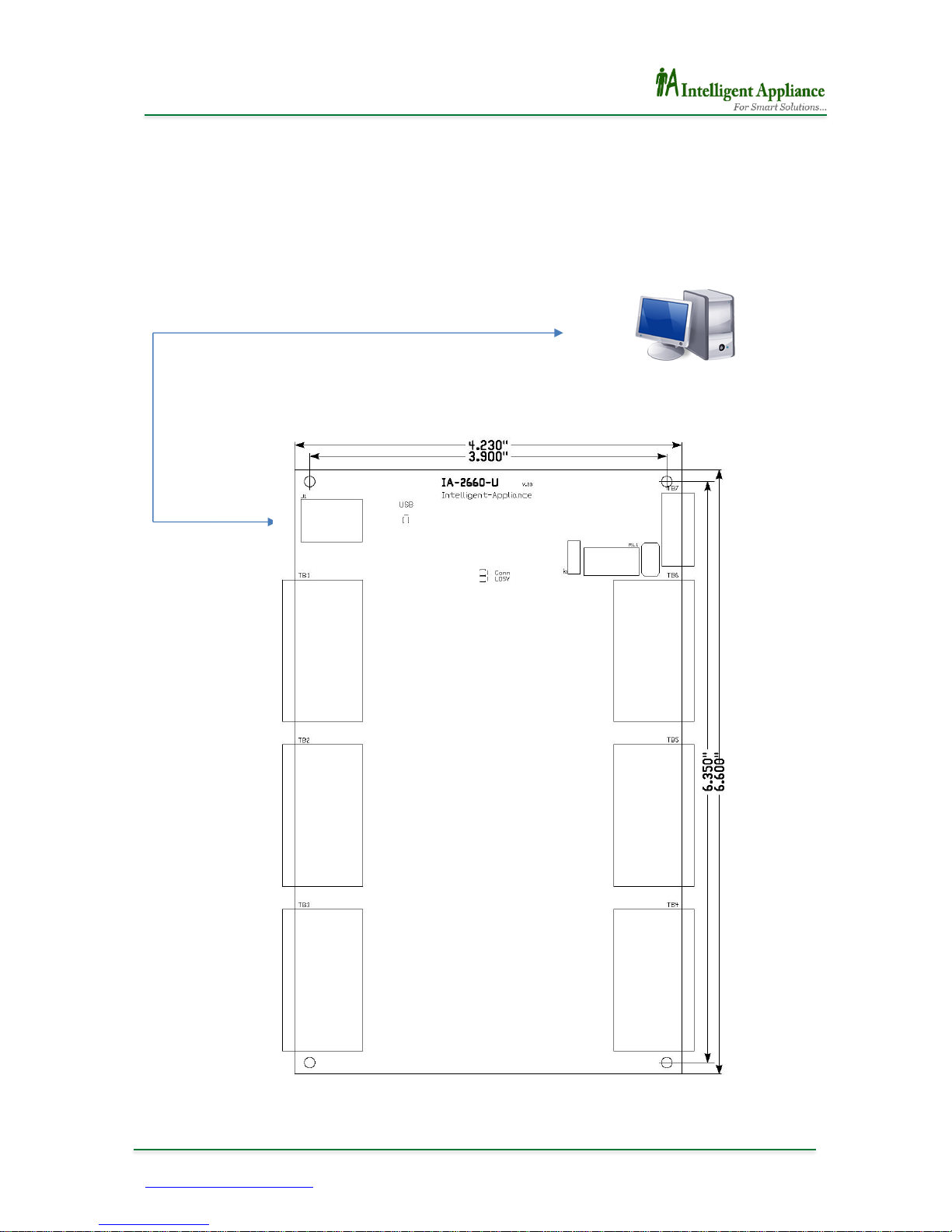
Installation
System Wiring
USB
Host PC
USB
Page 8
IA-2660-Ui
8
www.intelligent-appliance.com Specifications are subject to change without notice
Isolated TCP/IP
96 Digital TTL/LVTTL
Pluggable Terminal Blocks
Pin Assignment
J1 – Main Port (USB)
TB1, TB2, TB3
TB4, TB5, TB6 - Digital Input/ Output signals
TB7 – Power Supply and Relay
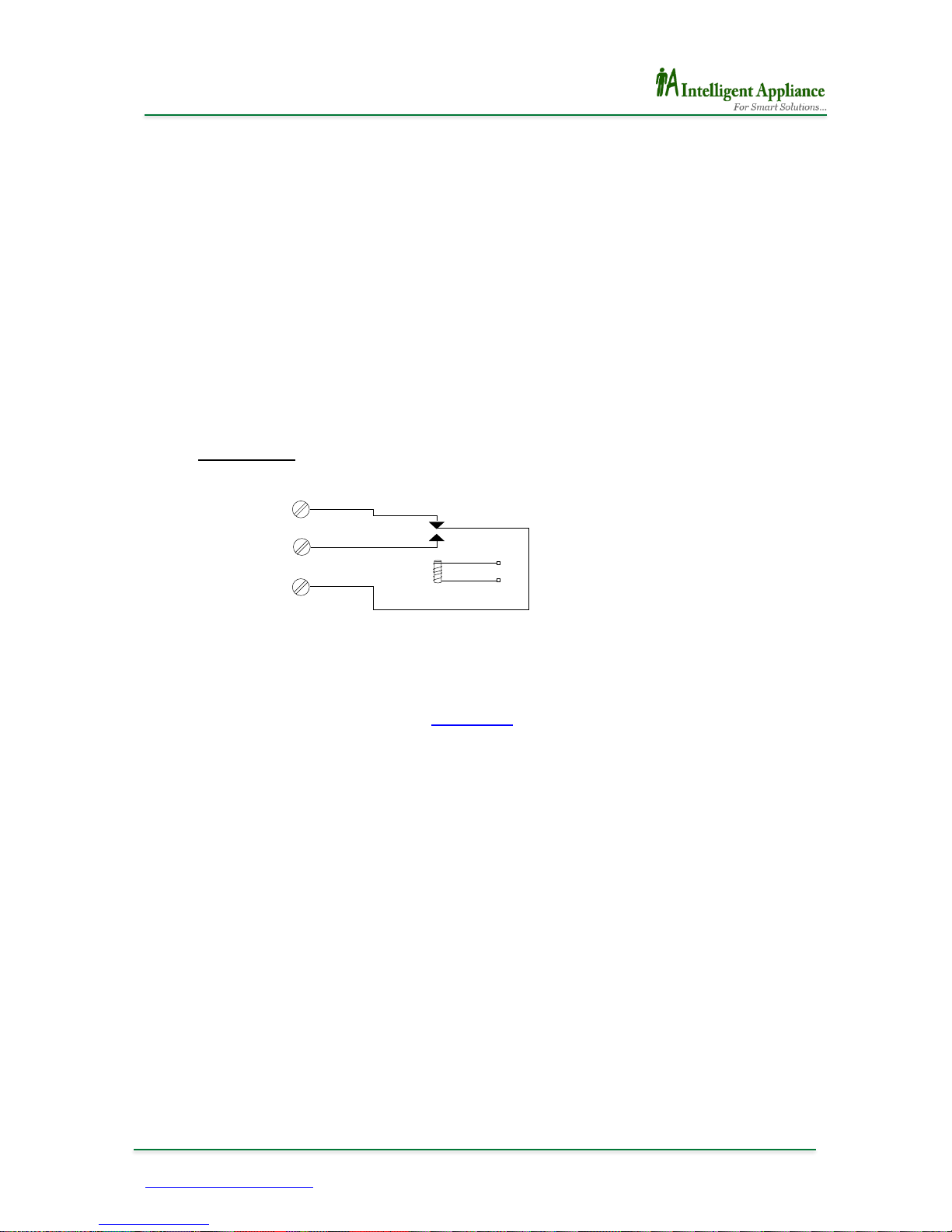
Auxiliary Relay Contact Layout
SPDT, Form C
In order to activate Auxiliary Relay, refer to !aaSdd <CR> command.
K1
NC
NO
C
Page 9
IA-2660-Ui
9
www.intelligent-appliance.com Specifications are subject to change without notice
Isolated TCP/IP
96 Digital TTL/LVTTL
Pluggable Terminal Blocks
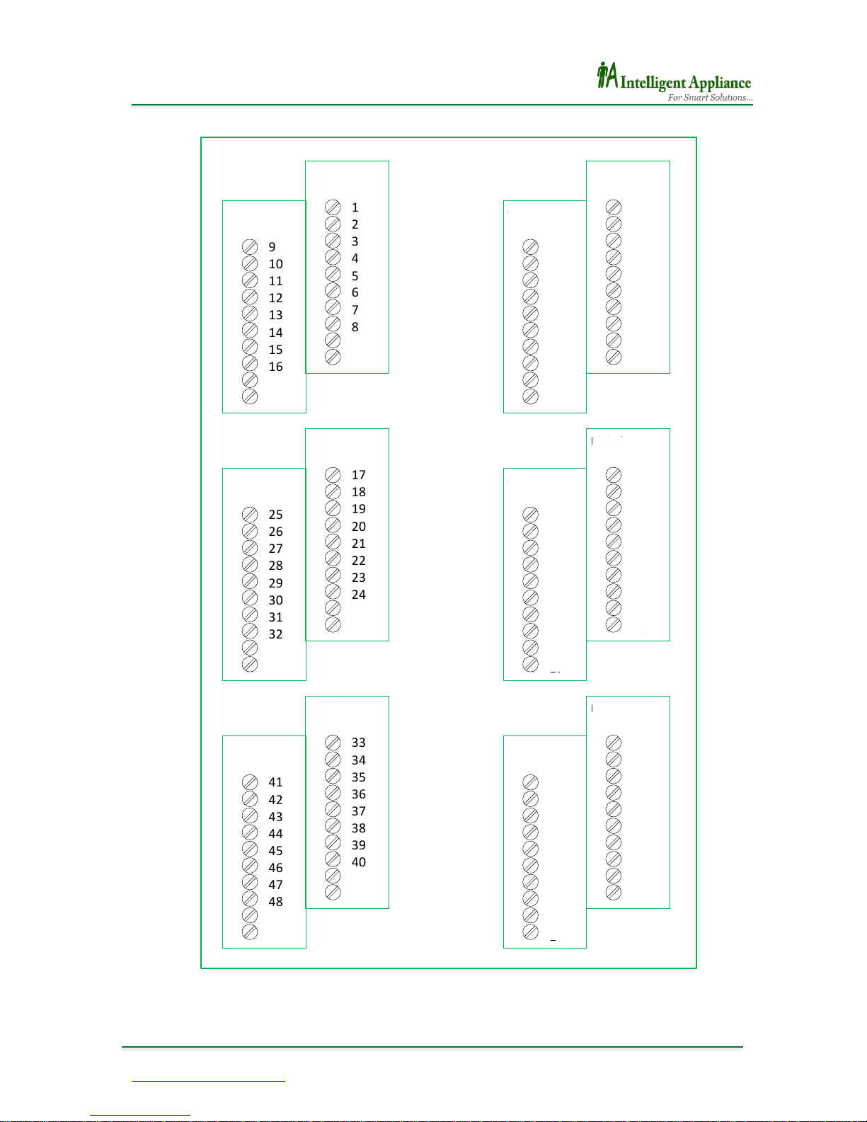
Digital Input / Output Terminal Block
1
2
3
4
5
6
7
8
Ei1
GND
Digital Input
TB1-Upper
9
10
11
12
13
14
15
16
Ei1
GND
Digital Input
TB1-Lower
17
18
19
20
21
22
23
24
Ei2
GND
Digital Input
TB2-Upper
25
26
27
28
29
30
31
32
Ei2
GND
Digital Input
TB2-Lower
33
34
35
36
37
38
39
40
Ei3
GND
Digital Input
TB3-Upper
41
42
43
44
45
46
47
48
Ei3
GND
Digital Input
TB3-Lower
GND
Eo3
48
47
46
45
44
43
42
41
Digital Output
TB6-Lower
GND
Eo3
40
39
38
37
36
35
34
33
Digital Output
TB6-Upper
GND
Eo2
32
31
30
29
28
27
26
25
Digital Output
TB5-Lower
GND
Eo2
24
23
22
21
20
19
18
17
Digital Output
TB5-Upper
GND
Eo1
16
15
14
13
12
11
10
9
Digital Output
TB4-Lower
GND
Eo1
8
7
6
5
4
3
2
1
Digital Output
TB4-Upper
I/O
I/O
I/O
I/O
I/O
I/O
I/O
I/O
I/O
I/O
I/O
I/O
E1
GND
E5
GND
E6
GND
E4
GND
E3
GND
E2
GND
GND
E7
56
55
54
53
52
51
50
49
GND
E8
64
63
62
61
60
59
58
57
GND
E9
72
71
70
69
68
67
66
65
GND
E10
80
79
78
77
76
75
74
73
GND
E11
88
87
86
85
84
83
82
81
GND
E12
96
95
94
93
92
91
90
89
Page 10
IA-2660-Ui
10
www.intelligent-appliance.com Specifications are subject to change without notice
Isolated TCP/IP
96 Digital TTL/LVTTL
Pluggable Terminal Blocks
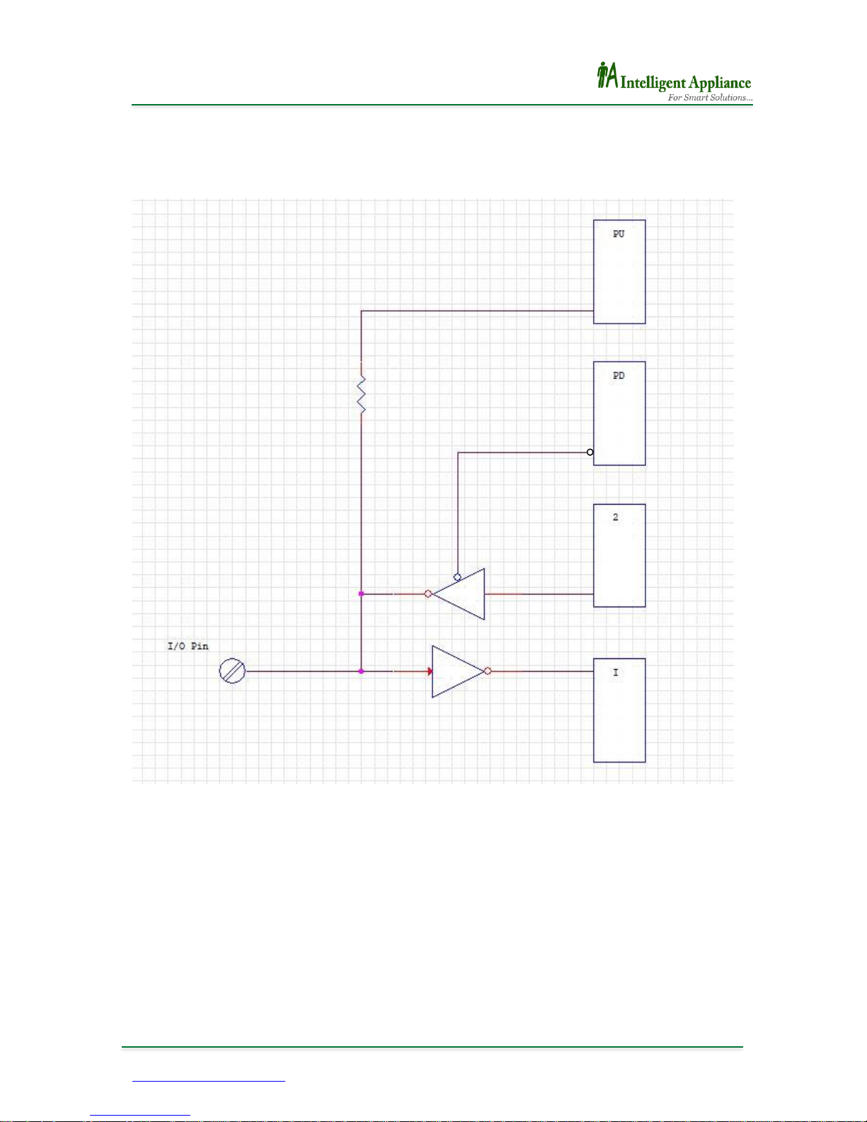
Internal Circuits
Page 11
IA-2660-Ui
11
www.intelligent-appliance.com Specifications are subject to change without notice
Isolated TCP/IP
96 Digital TTL/LVTTL
Pluggable Terminal Blocks
Software Installation
USB Port setup
Connect USB A/B Cable between the device to the host computer.
The computer informs on locating a new USB device, and asks for S/W drivers.
Kindly choose the USB-Drivers directory on the IA-3000 CD or from our website:
www.intelligent-appliance.com, and complete the task by pressing ‘Next’ and ‘Finish’ while
asked for.
Job done will be accomplished by a steady lilting of the USB led on the device unit, and by a
creation of new Serial COM that can be easily found on the Device Manager screen.
At this stage you can easily control the device I/O’s by either any serial control software, or
by the IA3000Util Utility, provided in the IA-3000 CD (see next page).
Locating the new COM port
Start the ‘Device Manager’ utility. (Usually by selecting ‘My Computer’, Right Clicking the
mouse button, choosing manage, Left Clicking and then double Left clicking on the Device
Manager will list hardware items).
Select the ‘+’ character to the left of the ‘Ports (COM&LPT)’, and you’ll get a line that will
define for example: ‘USB Serial Port (COM4)’.
This line informs us that we should refer to COM4, in this case, in order to control the device
while connected to this computer through its USB port.
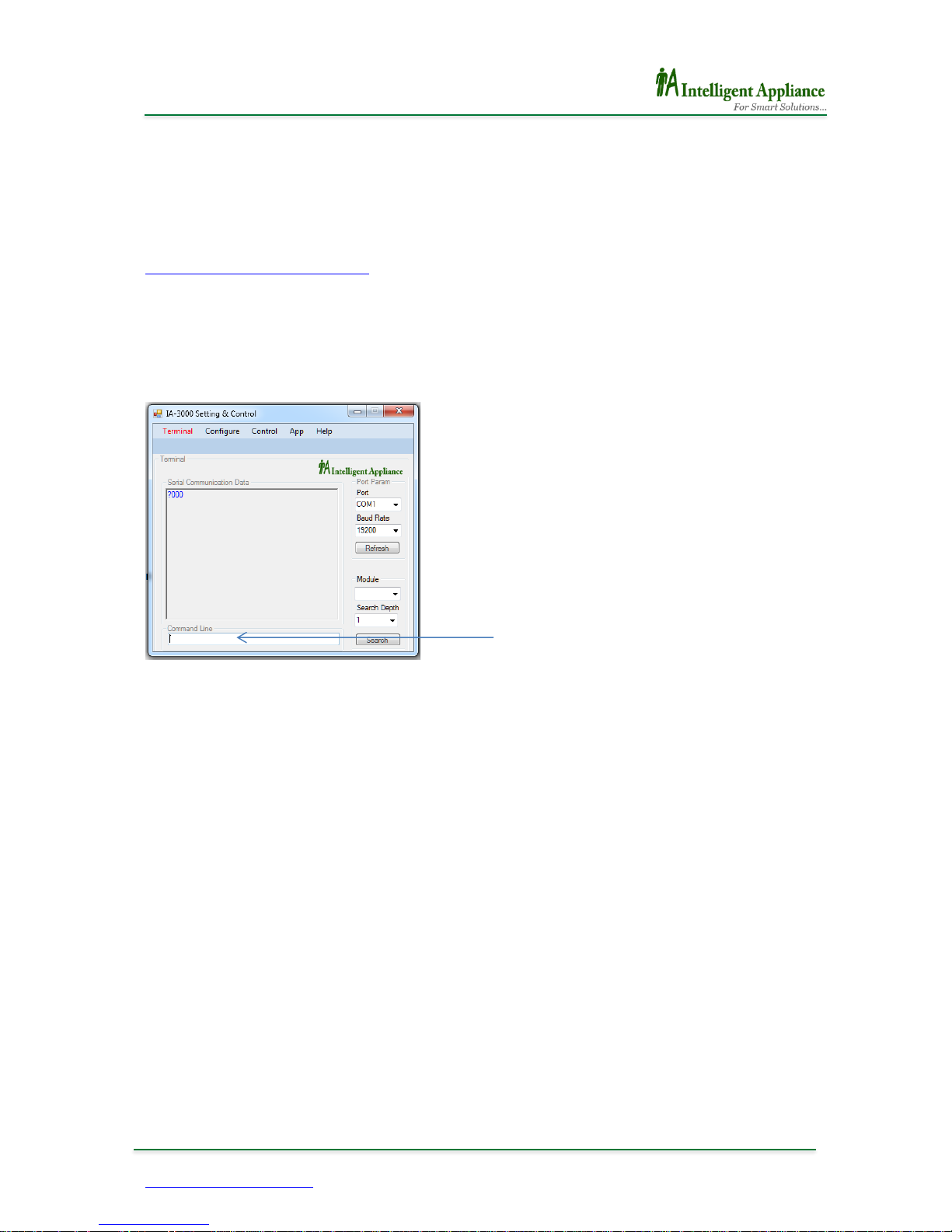
IA3000Util Command Line
Page 12
IA-2660-Ui
12
www.intelligent-appliance.com Specifications are subject to change without notice
Isolated TCP/IP
96 Digital TTL/LVTTL
Pluggable Terminal Blocks
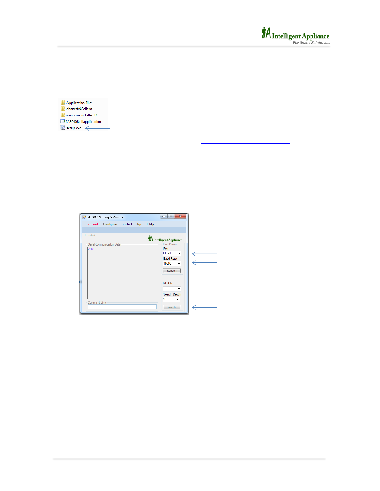
IA-3000 Utility
Install the IA3000Util Utility in your computer by clicking on the ‘Setup' icon in the ‘IA-
Utility’ directory, on the IA-3000 CD.
Or download it from our online Knowledge Base. (www.intelligent-appliance.com)
Handling IA-3000 Utility
1. Start the IA3000Util Utility by pressing ‘Start Manu’ on the computer’s main screen,
select ‘All Programs’, and finally ‘IA3000Util'.
2. Select the appropriate COM
3. Select ‘19200’ to fit into the right of the ‘Baud’ label (in case that the device is at its
default setting stage).
4. Press the ‘Search’ button and wait for the utility to list all chained items.
5. Select the desired device out of the Module list that appears above the ‘Search’
button.
Step 2
Step 3
Step 4
Page 13

IA-2660-Ui
13
www.intelligent-appliance.com Specifications are subject to change without notice
Isolated TCP/IP
96 Digital TTL/LVTTL
Pluggable Terminal Blocks
6. Once the device is selected, its form will be shown on the control panel label.
7. Left clicking the buttons will activate or dis-activate the appropriate I/O.
Step 6
Page 14

IA-2660-Ui
14
www.intelligent-appliance.com Specifications are subject to change without notice
Isolated TCP/IP
96 Digital TTL/LVTTL
Pluggable Terminal Blocks
Command Set
The following table is a quick reference table for the IA-2660-Ui, A host computer / PLC may
control the IA-2660-Ui by simply sending ASCII commands though a standard COM port.
Each command is structured from a delimiter character, modules address, command
character, data if any carriage returns character. All commands must use UPPER CASE
characters.
COMMAND SET.............................................................................................................................................. 14
?AA0 – GET DEVICE NAME ...................................................................................................................................... 15
?AA1 – GET DEVICE FIRMWARE VERSION ................................................................................................................... 16
?AA2 – GET DIGITAL OUTPUT STATUS ....................................................................................................................... 17
?AA3NN – GET BIT STATE ....................................................................................................................................... 19
?AA5 – GET DEVICE MODE (REGISTER #50) ............................................................................................................... 20
?AA51 – GET DEVICE MODE (REGISTER #51) ............................................................................................................. 21
?AAI – GET DIGITAL INPUTS STATUS .......................................................................................................................... 22
?AAID – GET MODULE’S ID NUMBER ........................................................................................................................ 24
?AAPD – GET DEVICE I/O STRUCTURE SETTINGS ......................................................................................................... 25
?AAPU – GET PULL-UPS SETTINGS ........................................................................................................................... 26
?AAS – GET RELAY STATE ....................................................................................................................................... 27
!AA2DDDDDDDDDDDDDDDDDDDDDDDD – SET OUTPUT STATUS ..................................................................................... 28
!AA3DD – ACTIVATE OUTPUT N (00-5F) ................................................................................................................... 29
!AA4DD – DE ACTIVATE OUTPUT N........................................................................................................................... 30
!AA5DD – SET DEVICE OPERATION MODE (REG #50).................................................................................................. 31
!AA51DD – SET INTERNAL CIRCUIT OPERATION VOLTAGE 3V / 5V (REG #51) ................................................................. 32
!AA6DD – SET BAUD RATE ....................................................................................................................................... 33
!AA7DD – SET MODULE’S ADDRESS ........................................................................................................................... 34
!AABNDD – SET RELAYS STATUS AT LEVEL (N=0-B) ..................................................................................................... 35
!AAPDDDDD – SET MODULE’S I/O STRUCTURE ........................................................................................................... 36
!AAPUDD – SET PULL-UP SOURCE. ........................................................................................................................... 37
!AASDD – ACTIVATE/DEACTIVATE AUXILIARY RELAY ..................................................................................................... 38
Page 15

IA-2660-Ui
15
www.intelligent-appliance.com Specifications are subject to change without notice
Isolated TCP/IP
96 Digital TTL/LVTTL
Pluggable Terminal Blocks
?aa0 – Get device name
Description
Request the Device model name. Can be used to identify the connected
module type at the specified address.
Syntax
?aa0<CR>
?
Delimiter character
aa
Hexadecimal address of the device
0
Get device Model command
<CR>
Carriage Return - End of command
Response
_nnnn<CR> if the command was valid
_
Response delimiter
nnnn
A string containing the device name
<CR>
Carriage Return - end of response
Example
Command: ?010<CR>
Response: _2660<CR>
Request the device at address 01Hex to send its model name.
The response indicates that the command was successful and that the
device at this address is IA-2660-Ui
Page 16

IA-2660-Ui
16
www.intelligent-appliance.com Specifications are subject to change without notice
Isolated TCP/IP
96 Digital TTL/LVTTL
Pluggable Terminal Blocks
?aa1 – Get device firmware version
Description
Request the Device version
Syntax
?aa1<CR>
?
Delimiter character
aa
Hexadecimal address of the device
1
Get device Version command
<CR>
Carriage Return - End of command
Response
_nnnn<CR> if the command was valid
_
Response delimiter
nnnn
A string containing the device version
<CR>
Carriage Return - end of response
Example
Command: ?001<CR>
Response: _A106<CR>
Request the device at address 00 Hex to send its version.
The response indicates that the command was successful and that the
device version at this address is A1.06
Page 17

IA-2660-Ui
17
www.intelligent-appliance.com Specifications are subject to change without notice
Isolated TCP/IP
96 Digital TTL/LVTTL
Pluggable Terminal Blocks
?aa2 – Get Digital output status
Description
Read Digital outputs Register status
Syntax
?aa2<CR>
?
Delimiter character
aa
Hexadecimal address of the device
2
Read outputs status
<CR>
Carriage Return - End of command
Response
_ABCDEFGHIJKLMNOPQRSTUVWX<CR> if the command was valid
_
Delimiter character
A 1st output nibble
B 2nd output nibble
C 3rd output nibble
D 4th output nibble
E 5th output nibble
F 6th output nibble
G 7th output nibble
H 8th output nibble
I 9th output nibble
J 10th output nibble
K 11th output nibble
L 12th output nibble
M
13th output nibble
N
14th output nibble
O
15th output nibble
P
16th output nibble
Q
17th output nibble
R
18th output nibble
S
19th output nibble
T
20th output nibble
U
21st output nibble
V
22nd output nibble
W
23rd output nibble
X
24th output nibble
Page 18

IA-2660-Ui
18
www.intelligent-appliance.com Specifications are subject to change without notice
Isolated TCP/IP
96 Digital TTL/LVTTL
Pluggable Terminal Blocks
Output Bit Table
Value
8 4 2 1 8 4 2 1 8 4 2
1
Bit
3 2 1 0 3 2 1 0 3 2 1
0
I/O
95
94
93
92 91
90
89
88
3 2 1
0
Nibble
A B
X
Bit 0 refers to input Pin #1
Bit 95 refers to input Pin #96
Examples
Command: ?002<CR>
Response: _ 100000000000000000000005<CR>
Input #1, #3 and #93 are activated.
Page 19

IA-2660-Ui
19
www.intelligent-appliance.com Specifications are subject to change without notice
Isolated TCP/IP
96 Digital TTL/LVTTL
Pluggable Terminal Blocks
?aa3nn – Get Bit State
Description
This command Picks defined Bit State
Syntax
?aa3nn<CR>
?
Delimiter character
aa
Hexadecimal address of the device
3
Acquiring defined Bit DATA command
nn
Bit location. ‘00’ for Pin #1, ‘01’ for Pin #2 and
‘5F’ for Pin #96.
<CR>
Carriage Return - End of command
Response
_nn b<CR> if the command was valid
nn
Bit location
b
Bit value. May be ‘0’ or ‘1’.
<CR>
Carriage Return - End of response
Example
Command: ?00300<CR>
Response: _00 1<CR>
In this example Bit 0 that represent Pin #1 shows Logic ‘1’ level
That means that there is a Positive Level at this Pin.
Page 20

IA-2660-Ui
20
www.intelligent-appliance.com Specifications are subject to change without notice
Isolated TCP/IP
96 Digital TTL/LVTTL
Pluggable Terminal Blocks
?aa5 – Get Device mode (Register #50)
Description
This command reads the module operation mode
Syntax
?aa5<CR>
?
Delimiter character
aa
Hexadecimal address of the device
5
System Mode command
<CR>
Carriage Return - End of command
Response
_dd<CR> if the command was valid
dd
Mode (00-FF)
82
Enable BR change
02
Report on command errors
00
Normal
<CR>
Carriage Return - End of command
Example
Command: ?005<CR>
Response: _82<CR>
In this example the module operation mode enables baud rate change.
It will also send error messages for invalid commands.
‘82’ Value must be changed to ‘Normal’ right after BR or Address are
changed.
‘Normal’ can be ‘00’ or ‘02’ or any other preferred value except ‘82’, as
otherwise both the BR or Address might be changed by mistake.
Page 21

IA-2660-Ui
21
www.intelligent-appliance.com Specifications are subject to change without notice
Isolated TCP/IP
96 Digital TTL/LVTTL
Pluggable Terminal Blocks
?aa51 – Get Device mode (Register #51)
Description
This command reads the device mode register #51 data.
Syntax
?aa51<CR>
?
Delimiter character
aa
Hexadecimal address of the device
51
Mode register #51 command
<CR>
Carriage Return - End of command
bit
Value (dd)
Function
Internal Voltage
4
1
10
3.3V 0 00
5V (Red Led) (Factory default)
Response
_dd<CR> if the command was valid
dd
Mode register #51
<CR>
Carriage Return - End of command
Example
Command: ?0051<CR>
Response: _10<CR>
In this example the Logic Circuit Internal Voltage is 3.3V
Page 22

IA-2660-Ui
22
www.intelligent-appliance.com Specifications are subject to change without notice
Isolated TCP/IP
96 Digital TTL/LVTTL
Pluggable Terminal Blocks
?aaI – Get Digital inputs status
Description
Read Digital inputs present status
Syntax
?aaI<CR>
?
Delimiter character
aa
Hexadecimal address of the device
I
Read inputs status
<CR>
Carriage Return - End of command
Response
_ABCDEFGHIJKLMNOPQRSTUVWX<CR> if the command was valid
_
Delimiter character
A 1st inputs nibble
B 2nd inputs nibble
C 3rd inputs nibble
D 4th inputs nibble
E 5th inputs nibble
F 6th inputs nibble
G 7th inputs nibble
H 8th inputs nibble
I 9th inputs nibble
J 10th inputs nibble
K 11th inputs nibble
L 12th inputs nibble
M
13th inputs nibble
N
14th inputs nibble
O
15th inputs nibble
P
16th inputs nibble
Q
17th inputs nibble
R
18th inputs nibble
S
19th inputs nibble
T
20th inputs nibble
U
21st inputs nibble
V
22nd inputs nibble
W
23rd inputs nibble
X
24th inputs nibble
Page 23

IA-2660-Ui
23
www.intelligent-appliance.com Specifications are subject to change without notice
Isolated TCP/IP
96 Digital TTL/LVTTL
Pluggable Terminal Blocks
Output Bit Table
Value
8 4 2 1 8 4 2 1 8 4 2
1
Bit
3 2 1 0 3 2 1 0 3 2 1
0
I/O
95
94
93
92 91
90
89
88
3 2 1
0
Nibble
A B
X
Bit 0 refers to input Pin #1
Bit 95 refers to input Pin #96
Examples
Command: ?00I<CR>
Response: _ 100000000000000000000005<CR>
Input #1, #3 and #93 are activated.
Page 24

IA-2660-Ui
24
www.intelligent-appliance.com Specifications are subject to change without notice
Isolated TCP/IP
96 Digital TTL/LVTTL
Pluggable Terminal Blocks
?aaID – Get module’s ID number
Description
This command reads the Device ID
Syntax
?aaID<CR>
?
Delimiter character
aa
Hexadecimal address of the device
ID
Command for read ID
<CR>
Carriage Return - End of command
Response
_ID nnnnnnnn
Example
Command: ?00ID<CR>
Response: _ID 00412534<CR>
In this example we read S/N of device #00
Page 25

IA-2660-Ui
25
www.intelligent-appliance.com Specifications are subject to change without notice
Isolated TCP/IP
96 Digital TTL/LVTTL
Pluggable Terminal Blocks
?aaPD – Get Device I/O Structure settings
Description
This command reads the module’s I/O Structure settings
Syntax
?aaPD<CR>
?
Delimiter character
aa
Hexadecimal address of the device
PD
Get Device I/O Structure settings
<CR>
Carriage Return - End of command
Response
_0ddd<CR> if the command was valid
_0ddd
I/O Structure (0000-0FFF)
<CR>
Carriage Return - End of response
Example
Command: ?00PD<CR>
Response: _0001<CR>
In this example the entire module is set to INPUT except the lowest
Byte.
_0000
All Device Bytes are set to INPUT
_0FFF
All Device Bytes are set to OUTPUT
_0800
All Bytes are set to INPUT except the highest one, that is set to
output (Pin 89-96)
Page 26

IA-2660-Ui
26
www.intelligent-appliance.com Specifications are subject to change without notice
Isolated TCP/IP
96 Digital TTL/LVTTL
Pluggable Terminal Blocks
?aaPU – Get Pull-ups settings
Description
This command reads the module’s Pull-ups settings
Syntax
?aaPU<CR>
?
Delimiter character
aa
Hexadecimal address of the device
PU
Get Pull-ups settings
<CR>
Carriage Return - End of command
Response
_dd<CR> if the command was valid
_dd
I/O Structure (00-3F)
<CR>
Carriage Return - End of response
Example
Command: ?00PD<CR>
Response: _01<CR>
In this example all Pull-ups are set to GND except the lowest
Word. Two lowest Bytes Pull-up source is Positive.
_00
All Device Pull-ups are set to GND
_3F
All Device Pull-ups are set to the Positive Voltage.
_20
All Pull-ups are set to GND except the highest two Bytes.
Page 27

IA-2660-Ui
27
www.intelligent-appliance.com Specifications are subject to change without notice
Isolated TCP/IP
96 Digital TTL/LVTTL
Pluggable Terminal Blocks
?aaS – Get Relay state
Description
This command reads the status of the relay.
Syntax
?aaS<CR>
?
Delimiter character
aa
Hexadecimal address of the device
S
Read relay status
<CR>
Carriage Return - End of command
Response
_dd<CR> if the command was valid
_
Delimiter character
dd
Relay state
<CR>
Carriage Return - End of response
Example
Command: ?00S<CR>
Response: _10<CR>
In this example Relay is Activated
Page 28

IA-2660-Ui
28
www.intelligent-appliance.com Specifications are subject to change without notice
Isolated TCP/IP
96 Digital TTL/LVTTL
Pluggable Terminal Blocks
!aa2dddddddddddddddddddddddd – Set output status
Description
This command defines module’s output state.
Syntax
!aa2dddddddddddddddddddddddd <CR>
!
Delimiter character
aa
Hexadecimal address of the device
2
System control command
d
Digital output activation command data for each nibble in hex
format
<CR>
Carriage Return - End of command
Response
| dddddddddddddddddddddddd
if the command was valid and if FB messages are enabled
Example
Command: !002100000000000000000000028<CR>
Response: |100000000000000000000028<CR>
This command will activate digital outputs #4, #6, #93.
Output Bit Table
Value
8 4 2 1 8 4 2 1 8 4 2
1
Bit
3 2 1 0 3 2 1 0 3 2 1
0
I/O
95
94
93
92 91
90
89
88
3 2 1
0
Nibble
A B
X
Page 29

IA-2660-Ui
29
www.intelligent-appliance.com Specifications are subject to change without notice
Isolated TCP/IP
96 Digital TTL/LVTTL
Pluggable Terminal Blocks
!aa3dd – Activate output N (00-5F)
Description
This command activates a single output.
Syntax
!aa3dd <CR>
!
Delimiter character
aa
Hexadecimal address of the device
3
Single output activation command
dd
N Output ID in hex format
<CR>
Carriage Return - End of command
Response
|Sdd if the command was valid
Example
Command: !00302<CR>
Response: |S02<CR>
This command will activate Output #3 only (!) all other Outputs will be
not changed.
Page 30

IA-2660-Ui
30
www.intelligent-appliance.com Specifications are subject to change without notice
Isolated TCP/IP
96 Digital TTL/LVTTL
Pluggable Terminal Blocks
!aa4dd – De activate Output N
Description
This command De activates a single output.
Syntax
!aa4dd <CR>
!
Delimiter character
aa
Hexadecimal address of the device
4
De activate output N command
dd
N Output ID in hex format
<CR>
Carriage Return - End of command
Response
|Cdd if the command was valid
Example
Command: !00402<CR>
Response: |C02<CR>
This command will De activate output #3 only (!) all other outputs state
will not be changed.
Page 31

IA-2660-Ui
31
www.intelligent-appliance.com Specifications are subject to change without notice
Isolated TCP/IP
96 Digital TTL/LVTTL
Pluggable Terminal Blocks
!aa5dd – Set device Operation Mode (REG #50)
Description
This command enables/disables error messages.
Syntax
!aa5dd <CR>
!
Delimiter character
aa
Hexadecimal address of the device
5
System mode command
dd
Mode (00-FF)
82
Enables BR and Address changes
02
Report on command errors
00
Normal (Factory default)
<CR>
Carriage Return - End of command
Response
|dd EE OK if the command was valid
Example
Command: !00582<CR>
Response: |82 EE OK
This command will enable BR changing and enable the device error
messages. (Error messages are sent in response to invalid commands)
and will disable baud rate changed by mistake.
Make sure setting a normal mode like ‘00’ or ‘02’’ right after changing
the BR to disable mistakenly done BR and Address changes.
Page 32

IA-2660-Ui
32
www.intelligent-appliance.com Specifications are subject to change without notice
Isolated TCP/IP
96 Digital TTL/LVTTL
Pluggable Terminal Blocks
!aa51dd – Set Internal circuit Operation Voltage 3V / 5V (REG #51)
Description
This command defines the Internal Circuit Internal Voltage 3V / 5V.
Syntax
!aa51dd <CR>
!
Delimiter character
aa
Hexadecimal address of the device
51
System mode command
dd
Mode register #51
<CR>
Carriage Return - End of command
bit
Value (dd)
Function
Internal Voltage
4
1
10
3.3V 0 00
5V (Red Led) (Factory default)
Response
|dd EE OK if the command was valid
Example
Command: !005110<CR>
Response: |10 EE OK
This command will define 3.3V as the Internal Voltage
NOTE!
The Internal Operation Voltage will affect the Digital Output Voltage.
Page 33

IA-2660-Ui
33
www.intelligent-appliance.com Specifications are subject to change without notice
Isolated TCP/IP
96 Digital TTL/LVTTL
Pluggable Terminal Blocks
!aa6dd – Set baud rate
Description
This command defines the devices baud rates.
Mode register #51 must be set to “82” first. (!00582)
Syntax
!aa6dd <CR>
!
Delimiter character
aa
Hexadecimal address of the device
6
Change device baud rate command
dd
Two characters representing the desired baud rate:
12
1200
24
2400
48
4800
96
9600
19
19200 (default)
38
38400
57
57600
11
115200
<CR>
Carriage Return - End of command
Response
|dd<CR> if the command was valid
|
Response delimiter
dd
New baud rate
<CR>
Carriage Return - End of response
Example
Command: !01696<CR>
Response: |96<CR>
Change the baud rate of the device at address 01Hex to 9600
1. Mode must be set to “82” first. (!00582)
2. Changes will take effect after the next power up. (Power off)
3. Make sure setting the mode back to normal right after changing
the BR.
Note
!
Page 34

IA-2660-Ui
34
www.intelligent-appliance.com Specifications are subject to change without notice
Isolated TCP/IP
96 Digital TTL/LVTTL
Pluggable Terminal Blocks
!aa7dd – Set module’s address
Description
Each device must have a unique network address.
This command defines a module’s address.
Syntax
!aa7dd <CR>
!
Delimiter character
aa
Hexadecimal address of the device
7
Change device baud rate command
dd
New Hexadecimal address
<CR>
Carriage Return - End of command
Response
|dd<CR> if the command was valid
Example
Command: !00701<CR>
Response: |01<CR>
Change the address of the device at address 0(Hex) to 1(Hex)
1. Factory default is 00Hex
2. In products chained system, each product must be set to a unique
address.
3. On chainable modules the updated address is displayed on the
boards 7 segment led display.
Note
!
Page 35

IA-2660-Ui
35
www.intelligent-appliance.com Specifications are subject to change without notice
Isolated TCP/IP
96 Digital TTL/LVTTL
Pluggable Terminal Blocks
!aaBndd – Set Relays Status at Level (n=0-B)
Description
This command sets the status of 8 relays at a time.
Syntax
!aaBndd <CR>
!
Delimiter character
aa
Hexadecimal address of the device
B
Change Byte Level command
n
#Byte to be set.
‘n’ is in the range of 0-3
dd
Byte data in hex format.
<CR>
Carriage Return - End of command
Response
|n dd<CR> if the command was valid
Example
Command: !00B124<CR>
Response: |1 24<CR>
This command will activate relays #11 and #14(!) all other relays will be
not changed.
Example
Command: !00BB14<CR>
Response: |B 14<CR>
This command will activate relays #91 and #93(!) all other relays will be
not changed.
Page 36

IA-2660-Ui
36
www.intelligent-appliance.com Specifications are subject to change without notice
Isolated TCP/IP
96 Digital TTL/LVTTL
Pluggable Terminal Blocks
!aaPDdddd – Set module’s I/O Structure
Description
Each device structure is built of 12 Groups of I/O circuits. This command
defines whether a certain group outputs are Enabled, or in other words it
defines whether this group should be referred to as an Input or an
Output.
Syntax
!aaPDdddd <CR>
!
Delimiter character
aa
Hexadecimal address of the device
PD
Sets a Group Direction to become an Input or an Output
0ddd
Groups Direction data, ‘1’ for Output ‘0’ for Input. 00 to 0B.
<CR>
Carriage Return - End of command
Response
|dddd<CR> if the command was valid
Example
Command: !00PD0020<CR>
Response: |0020<CR>
Sets the 6th group to output. This means that device Pin #41 to Pin #48
will become Outputs while all others Pins should be handled as Inputs.
1. !aa PD0000 Factory default (all inputs)
2. Setting device Structure should take place after having the
system designed and wired to avoid Output to Output erroneous
connection.
3. Whenever using this command please make sure not causing a
wrong connection like:
A. Output to Output connection.
B. Output to Positive Voltage connection.
C. Output to GND connection.
Note
!
Page 37

IA-2660-Ui
37
www.intelligent-appliance.com Specifications are subject to change without notice
Isolated TCP/IP
96 Digital TTL/LVTTL
Pluggable Terminal Blocks
!aaPUdd – Set Pull-up source.
Description
The device structure includes 6 groups of 16 Pull-ups each, that can be
tied either to +Vcc or to GND. I/O groups Pull-ups are set by pairs.
This command defines whether a Pull-up group is tied to +Vcc or to GND.
‘1’ for +Vcc, ‘0’ for GND.
Syntax
!aaPUdd <CR>
!
Delimiter character
aa
Hexadecimal address of the device
PU
Sets Pull-up source.
dd
Pull-ups source data, ‘1’ for +Vcc ‘0’ for GND. ‘00’ to ’05’.
<CR>
Carriage Return - End of command
Response
|dd<CR> if the command was valid
Example
Command: !00PU07<CR>
Response: |07<CR>
Sets the lowest 6 I/O groups Pull-ups to +VCC and all others to GND.
‘07’ meaning is that the three lowest Pull-up groups are set to +Vcc. This
means that the lowest 6 I/O groups Pull-ups are set to +Vcc as each Pullup group include two I/O groups.
1. !aa PU00 – Factory default
2. The Pull-ups may be tied either to +Vcc or to GND to best fit user
logic.
3. The Pull-ups has no effect on an I/O group that is set to “Output”.
Note
!
Page 38

IA-2660-Ui
38
www.intelligent-appliance.com Specifications are subject to change without notice
Isolated TCP/IP
96 Digital TTL/LVTTL
Pluggable Terminal Blocks
!aaSdd – Activate/Deactivate Auxiliary relay
Description
This command sets the Auxiliary Relay state.
Syntax
!aaSdd <CR>
!
Delimiter character
aa
Hexadecimal address of the device
S
Defines the Auxiliary Relay state.
dd
Auxiliary relay state. ‘10’ for Active ‘00’ for Off.
<CR>
Carriage Return - End of command
Response
|dd<CR> if the command was valid
Example
Command: !00S10<CR>
Response: |10<CR>
This command will activate the relay.
The default Relay status is OFF.
Note
!
 Loading...