


D-Flow
user manual

2 Intelligent Facility Solutions
Voltaje 220 - 240 V
Frecuencia
50 / 60 Hz
Aislamiento eléctrico
Clase II
Dimensiones
160 x 220 x 77 mm
Peso
0,8 Kg
Velocidad del aire
60 Km/h
Potencia Total
200 - 1.800 W
Consumo
0,9 - 7 A
rpm 9.000 -18.000 min
Temperatura aire
63
°C
Índice de protección
IP20
Nivel sonoro (a 2 m)
65 dBA
Voltaje 220 - 240 V
Frecuencia
50 / 60 Hz
Aislamiento eléctrico
Clase II
Dimensiones
160 x 220 x 77 mm
Peso
0,8 Kg
Velocidad del aire
60 Km/h
Potencia Total
200 - 1.800 W
Consumo
0,9 - 7 A
rpm 9.000 -18.000 min
Temperatura aire
63
°C
Índice de protección
IP20
Nivel sonoro (a 2 m)
65 dBA
Dimensiones
185 x 165 x 95 mm
Peso
0,75 Kg
Capacidad
1.250 m
l
Cantidad dispensada/pulsación
0,7 ml
Dimensiones
185 x 165 x 95 mm
Peso
0,75 Kg
Capacidad
1.250 m
l
Cantidad dispensada/pulsación
0,7 ml
Dimensiones
185 x 165 x 95 mm
Peso
0,75 Kg
Capacidad
1.250 m
l
Cantidad dispensada/pulsación
0,7 ml
Dimensiones
185 x 165 x 95 mm
Peso
0,75 Kg
Capacidad
1.250 m
l
Cantidad dispensada/pulsación
0,7 ml
HAND DRYERS
SENSOR OPERATED
Dualflow Plus
General description
The dualflow© Plus M14 240V is a fast, energy
efficient, ecologic, hygienic & stylish hand dryer.
“Hands in” model it has 2 pairs of IR sensors on
both sides of the upper covers
for instant hand
detection
Maximum air speed 410 Km/h.
Dries hands in only 8 / 15 seconds.
Motor power adjustable, allowing electricity
consumption to be regulated.
(Between 420 and
1.100W).
30 seconds safety timer.
Lowest noise level in its category. (62 dBA in ECO
mode).
Suitable for medium and high traffic facilities.
Easy maintenance.
Components & materials:
M14A: ABS cover, white finish.
M14AC: ABS cover, satin finish.
M14AB: ABS cover, black finish.
High speed class F universal brush motor,
adjustable from 19000 to 30000 rpm.
Biocote® antimicrobial and antibacterial protection
technology based on silver ions. These ions inhibit
the reproduction of micro-organisms in the product
throughout its lifetime.
H13 HEPA filt
er which eliminates more than the
99% of particles.
Base plate made in plastic PA6V0.
Removable water tank which it has valve for
emptying.
LED front light for fast diagnosis of the dryer (green
- machine running, blue - full tank, red - check
engine).
Optical and acoustic warning full tank.
No heating element.
Odor neutralizer (optional).
Technical Specifications:
(*) According to UNE EN ISO 11201:2010 V2 standard.
Dimensions:
Voltage
220- 240 V
Frequency
50/60 Hz
Electrical Isolation
Class I
Total power
420 – 1,100 W
Consumption
3.2 – 5 A
Motor power
420 – 1,100 W
Rpm
19,000 – 30,000
Heating element power
No Heating Element
Dimensions
665x320x228 mm
Weight
8.3 Kg
Cover thickness
3 mm
Drying time
8-15 sec
Effective airflow
94-165m3/h –1,570-2,750 l/min
Air velocity
234 – 410 Km/h
Air temperature (10 cm
distance/21ºC)
35 ºC
Sound pressure
(*)
(at 2m)
62 – 72 dBA
Protection rating
IPX4
white finish satin finish
M14AB
black finish

D-Flow 3
Operation
Place the hands between the air outflow valves, inside the hand dryer.
The dryer will start automatically, and go on with no interruption as long
as the hands are kept in the detection range of the sensor. Move the
hands vertically in order to dry them completely. The appliance will stop 2
seconds after the hands are removed from the airflow.
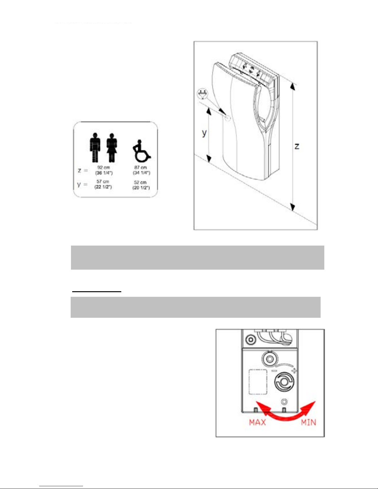
Mounting Recommended heights distance from the floor
Certificates & Qualifications

4 Intelligent Facility Solutions
Before to carry on any operation, please read carefully and take into account the
following safety instructions:
- Only a qualified technician can install, adjust and maintain this device. All this operations must
be always done according to the current legal European Standards of installation and according
the local installation regulations as well.
- Be careful when the casing of the appliance is dismantled because active parts of the device
become accessible and then there is a potential risk of an electric shock.
- Before any electrical manipulation, the electrical current must be cut in order to avoid any
electric shock risk
- The device must be fixed out of reach of a water source in order to fulfil the security distances
marked into the current IEC standards and as the following figure shows:
- Be careful because local installation requirements can ask more than 1 m of safety distance.
Take into account these local requirements as well.
- Hairdryers must be fixed out of reach of a person taking a bath or a shower.
- Means for disconnection, with contact separations at least 3 mm (0.12"), must be incorporated
in the fixing wiring involving all poles, accordingly to the current legal European Standards.
- The installer must make sure that the electric system is grounded in accordance with the law in
force.
- This appliance can be used by children aged from 8 years and above and persons with reduced
physical, sensory or mental capabilities or lack of experience and knowledge if they have been
given supervision or instruction concerning use of the appliance in a safe way and understand
the hazards involved. Children shall not play with the appliance. Cleaning and user
maintenance shall not be made by children without supervision.
- The device could not be installed on a normally inflammable surface.
- To fix the hand dryer to the wall follow the instructions of this manual and use the template
provided with the device as well. To fix the machine with adhesives or similar methods is
forbidden by the European safety standards.
SAFETY INSTRUCTIONS
ENGLISH
D-Flow 5
www.mediclinics.com
‘Dualflow Plus’ range hand dryers offer the following technical features:
Automatic operation. Hand detection is based on Infra Red (IR) movement sensors.
Two pairs of those sensors emit a continuous beam of IR light. The introduction of the
hands causes the interruption of the IR light beam and switch on the dryer.
The speed of the air generated by the hand dryer can be adjusted, to achieve an
optimum balance between the drying power and noise level.
Available finishes:
- White (M14A)
- Satin (M14ACS)
Dimensions: 656 mm (H) x 320 mm (W) x 226 mm (D).
Weight: 8.3 Kg
Mounting: Surface.
Means for disconnection with contact separations at least 3 mm (0.12")
must be incorporated in the fixing wiring.
INTRODUCTION
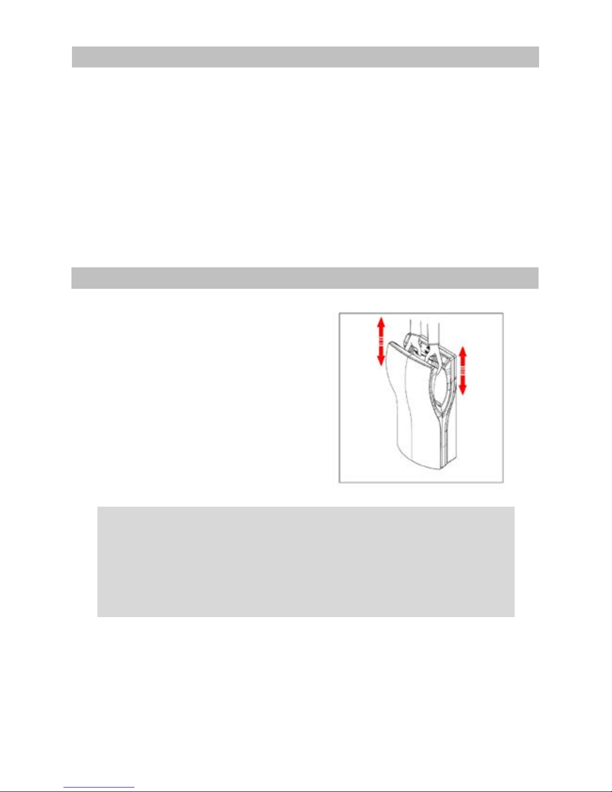
OPERATION
Figure 1
Hands must be introduced inside. Hand dryer starts
automatically after introducing hands.
Move hands vertically (as shown in Fig.1) in order
to dry them completely.
Green light (in standby state) led on top becomes to
orange colour when dryer is in use.
Maximum continuous operation time is T = 30 sec.
Drying time is less to it (Td ≈ 8 -12 sec).
After removing hands, dryer turns off automatically.
This appliance can be used by children aged from 8 years or above and
persons with reduced physical, sensory or mental capabilities or lack of
experience and knowledge if they have been given supervision or instruction
concerning use of the appliance in a safe way and understand the hazards
involved. Children shall not play with the appliance.
Cleaning and user maintenance shall not be made by people without the
proper training.

6 Intelligent Facility Solutions
Introduction
‘Dualflow Plus’ family of hand dryers offers the technical features as follows:
Automatic operation. Drying cycle starts when putting hands in. Two couple of IR
sensors detect hands introduction.
Dryer is a class I (earthed) electrical insulation device.
Drying process is based on powerful air curtains which remove water from hands.
Hand dryer has no heating element.
Speed of air can be adjusted in order to achieve an optimum balance between drying
power and noise level.
Light leds on top supply some information referred to the status of hand dryer.
Maximum time of continuous operation is T max = 30 sec.
Water from hands is collected in a removable tank which may be emptied and cleaned.
An HEPA filter is incorporated in the aspiration area whose state should be reviewed
periodically. The place of fitting the air inlet filter allows easy removal and replacement.
Optionally, in the aspiration area, an air-freshener can be incorporated.
Installation
ONLY A QUALIFIED TECHNICIAN CAN INSTALL, ADJUST AND MAINTAIN THIS HAND
DRYER.
The installation of the appliance is only allowed on fixed wiring.
Means for disconnection of the mains with contact separations at least 3 mm (0.12”) must be
incorporated in the fixing wiring.
The installer must make sure that the electric system is grounded in accordance with the law in
force.
Make sure that the electric system has a high-sensitivity breaker I n ≤ 0.03 A.
Make sure that the machine is disconnected from the electric power supply, before performing
maintenance operation.
To install the hand dryer follow the pictures contained in the figure 2.
The hand dryer must be fitted to the wall by using the upper metal plate (support) which is
supplied.
INSTALLATION AND MAINTENANCE BOOK (TECHNICAL STAFF)

D-Flow 7
www.mediclinics.com
After fitting the metal plate, the hand dryer should be hung on it. The lower screw fits safely the
appliance to the wall. So, to assemble the hand dryer the following steps must be done:
Make five 8 mm (0.31”) diameter drill holes in the wall using the provided template (1).
Clean the dust away and insert the wall plugs.
Screw the upper plate to the wall (2).
Plastic covers which protect the terminal block (inlet power supply) must be removed (3).
The hand dryer should be hung on the metal support which has been fitted to the wall (4).
Pass the electrical cables from mains through the 22 mm diameter hole located in the rear
plastic base3 plate. (5).
Connect the electrical wires to the hand dryer terminal block.
Two phases (N,L) and earth wires must be screwed in the right ways of the terminal block,
as indicated by the engraved letters (6).
After this operation has been done, plastic covers must be placed correctly (10).
Remove the air inlet filter casing (7).
Firmly place the lower screw for fixing the appliance completely (8).
Put the inlet air casing to its location (9).
Figure 2
8 Intelligent Facility Solutions
-14-
ATTENTION: WHEN THE CASING IS DISMANTELED ACTIVE PARTS OF THE DEVICE
BECOME ACCESSIBLE.
Installation height must be the showed in figure nº 3.
Maintenance
ONLY A QUALIFIED TECHNICIAN CAN INSTALL, ADJUST AND MAINTAIN THIS HAND
DRYER.
Adjust the speed of the motor
To adjust the speed of the motor turn
the sensor potentiometer wheel
as the picture 4 shows.
Figure 4
Figure 3

D-Flow 9
www.mediclinics.com
Pilot light information
Light leds on the top of the hand dryer (see figure 5) give advice about:
1: Standby (green colour) or
operation status (orange colour).
2: Red colour led bright when motor
has a problem of consumption
(due to brushes which may be wearing
out or due to a blocked or locked sate of motor).
3.- Blue colour led bright when cabinet of water is full.
Air filter
Air filter must be changed as the pictures of figure nº 6 shows.
No smell load charge
Figure nº 7 shows how to install the no smell charge.
Figure 5
Figure 6
Figure 7

10 Intelligent Facility Solutions
Water tank.
Water from hands drops directly to a removable water tank. When water from the removable
water tank reaches the ‘full level’ an acoustic alarm sounds and the blue pilot light bright (see
Fig. 5). In this case, water in the tank must be emptied.
Two options to remove the water from the water tank are available:
I. Press the two lateral clips and pull down the water tank, as the picture 8 shows.
Remove the water tank from its fitting place, empty and clean the tank and
re-place it.
II. Press the push button as indicated in Fig. 9 until remove all the water contained into the
water tank.
CONNECTION DIAGRAM
Figure 10
Figure 8 Figure 9

D-Flow 11
www.mediclinics.com
COMPONENT
NUMBER
CODE
Motor set 1 RC9111003SMD
Electronic control 2 RC9121012SMD
Air filter set 3 RCFILTROHEPA1
HEPA filter 4 RCFILTROHEPA2
Air-freshener 5 9481002
Figure 11
DANGER.
Electric shock risk
- The installer must make sure that the electric system is
grounded in accordance with the law in force.
- Make sure that the electric system has a high-sensitivity
breaker I n ≤ 0.03 A.
- Make sure the machine is disconnected from electric
power supply, before performing maintenance operation.
BASIC EXPLODED VIEW

12 Intelligent Facility Solutions
MANUAL DE MANTENIMIENTO
MAINTENANACE MANUAL
M14A / M14ACS DUALFLOW PLUS
Normas de seguridad
Todo proceso de instalación, mantenimiento y reparación debe ser
efectuado por personal técnico cualificado.
Mediclinics le recuerda la importancia de:
1.
Familiarizarse con el equipo y leer detenidamente el manual de
usuario antes de su manipulación.
2.
Desconectar la fuente de energía antes de iniciar cualquier proceso de
reparación o mantenimiento.
3. Actuar con precaución de acu
erdo a los procedimientos descritos en el
presente manual.
Mantenimiento general
Mantenimiento Preventivo – Limpieza
Inspeccionar las unidades con una periodicidad anual o semestral,
en
función de la carga de trabajo de la secadora.
Limpiar las partes activas de la unidad, como son: el motor, l
os detectores
LED y la placa electrónica, con un cepillo o pincel de cerdas suaves.
Mantener las aberturas de entrada y salida de aire libres de polvo y otras
obstrucciones, utilizando un cepillo o pincel de cerdas suaves.
Mantenimiento Correctivo – Recambios
Puede solicitar recambios de los elementos referenciados en el presente
manual, al servicio de recambios y reparaciones de Mediclinics.
C/ Casanova, 93. Pral. 2ª 08011 Barcelona.
Tel: 934 516 009. Fax: 934 516 367. Email: sca@mediclinics.com
Safety regulations
All installation, maintenance and repair tasks must be performed
by
qualified technicians.
Mediclinics reminds the importance of:
1. Becoming familiar with the equipment and carefully
reading the
user manual before handling.
2. Disconnecting power before
beginning any repair or maintenance
task.
3. Act with caution according to the procedures included
in this
manual.
General maintenance
Preventive Maintenance - Cleaning
Inspect the units annually or quarterly
, depending on the dryer’s
operating cycles.
Clean the active parts of the unit, such as: the motor, the
LED
detectors and the electronic circuit board with a soft brush.
Maintain the air inlet and outlet free of dust and other obstructions; use
a soft flat ended brush.
Corrective Maintenance – Spare Parts
You can order spare parts of the components shown herein.
Contact your closest dealer for further information.

D-Flow 13
LEYENDA DE LOS INDICADORES LED /LED INDICATORS LEGEND
Esperar 3-5 segundos a que la máquina se estabilize antes de diagnosticar algún problema.
Wait 3-5 seconds for the machine to stabilize before diagnosis of any problems.
Verde
Green
Off
Off
El secador está listo para funcionar en cuanto se introduzcan las manos.
The dryer is ready to run as soon as the hands are introduced.
Naranja
Orange
Off
Off
El secador está detectando las manos y el motor está funcionando correctamente.
The dryer is detecting the hands and the engine is running properly.
Off
Rojo
Red
Off
Avería en la electrónica o el motor
Electronics or motor are not working properly.
Naranja
Orange
Rojo
Red
Off
El secador está detectando las manos pero el motor no funciona correctamente.
Hands are detected but the engine is not working properly.
Verde o naranja
Green or Orange
Off
Azul
Blue
El depósito de agua está lleno. Sonará un pitido intermitente adicionalmente
The water tank is full. An intermittent whistle will sound additionally
Off
Off
Off
El secador está desconectado.
The dryer is disconnected.

14 Intelligent Facility Solutions
DESMONTAJE DEL FRONTAL - FRONT COVER REMOVAL
Extraiga el conjunto filtro, desclipándolo de la base.
___________________
Remove the filter assembly by unclipping it from the base.
Desatornillar, usando una llave allen de 2,5 mm, los 4
tornillos que sujetan el frontal a la base.
___________________
Unscrew the four screws securing the front cover to the
base. Use a 2.5 mm hexagonal spanner.
Mediante un suave pero firme tirón separe el frontal de la
base.
Después desliza el frontal hacia la parte superior.
___________________
With a gentle but steady pull separate the front of the base.
Then slide the front to the top.
Para realizar el montaje del frontal, siga los pasos anteriores en orden inverso.
To fit the front cover, follow the previous steps in reverse order.

D-Flow 15
CAMBIO DE MOTOR - MOTOR REPLACEMENT
Extraiga el conjunto filtro, desclipandolo de la base.
___________________
Remove the filter assembly by unclipping it from the base.
Desatornillar, usando una llave allen de 2,5 mm, los 4
tornillos que sujetan el frontal a la base.
___________________
Unscrew the four screws securing the front cover to the
base. Use a 2.5 mm hexagonal spanner.
Mediante un suave pero firme tirón separe el frontal de la
base.
Después desliza el frontal hacia la parte superior.
___________________
With a gentle but steady pull separate the front of the base.
Then slide the front to the top.
Desatornille los tornillos de fijación de la tapa circuito. Use
un destornillador de punta PZ2.
___________________
Unscrew both screws securing the electronic circuit board
cover. Use a cross head PZ2 screwdriver.
Retire la tapa.
___________________
Remove the lid.

16 Intelligent Facility Solutions
Desconecte los cables de motor y alimentación de los
terminales de la placa electrónica.
___________________
Unplug the motor and power wires from the electronic
circuit board terminal blocks.
Corte la brida de sujeción de los cables de motor y
alimentación.
___________________
Cut the tie securing motor and power wires.
Desatornille los 6 tornillos que fijan la tapa motor a la base.
Use un destornillador de punta PZ2.
___________________
Unscrew the 6 screws fixing the motor cover. Use a cross
head PZ2 screwdriver.
Mediante un suave pero firme tirón separe la tapa motor
de
la base.
___________________
With a gentle but steady pull separate the motor cover of
the base.

D-Flow 17
Desconecte los cables de alimentación del motor
presionando el clip de seguridad del conector y tirando del
conector suavemente.
___________________
Unplug the motor power wires pushing the safety clip of the
faston and pulling the faston out carefully.
Extraiga el motor.
___________________
Remove the motor.
Instale el nuevo motor siguiendo los pasos anteriores en sentido inverso.
Fit the new motor by following the previous steps in reverse order.

18 Intelligent Facility Solutions
CAMBIO DE ESCOBILLAS - BRUSHES REPLACEMENT
En caso necesario revise el apartado de cómo retirar el motor antes de continuar.
___________________
If necessary review the motor replacement section before continuing.
Una vez que el motor está fuera de la secadora, afloje los
tornillos que sujetan la escobilla. Utilice un destornillador
de punta PH1.
___________________
Once the motor is removed from the dryer, loosen the
screws holding the brush. Use a cross head PH1
screwdriver.
Retire la escobilla.
___________________
Remove the motor brush.
Realice el mismo proceso con la segunda escobilla del motor.
Realice el montaje siguiendo los pasos anteriores en sentido inverso.
Carry out the same procedure for the second motor brush.
Fit the new brushes following the previous steps in reverse order.

D-Flow 19
CAMBIO DE PLACA ELECTRÓNICA - ELECTRONIC CIRCUIT BOARD REPLACEMENT
Extraiga el conjunto filtro, desclipandolo de la base.
___________________
Remove the filter assembly by unclipping it from the base.
Desatornillar, usando una llave allen de 2,5 mm, los 4
tornillos que sujetan el frontal a la base.
___________________
Unscrew the four screws securing the front cover to the
base. Use a 2.5 mm hexagonal spanner.
Mediante un suave pero firme tirón separe el frontal de la
base.
Después desliza el frontal hacia la parte superior.
___________________
With a gentle but steady pull separate the front of the base.
Then slide the front to the top.
Desatornille los tornillos de fijación de la tapa circuito. Use
un destornillador de punta PZ2.
___________________
Unscrew both screws securing the electronic circuit board
cover. Use a cross head PZ2 screwdriver.
Retire la tapa.
___________________
Remove the lid.

20 Intelligent Facility Solutions
Desconecte los cables de motor y alimentación de los
terminales de la placa electrónica.
___________________
Unplug the motor and power wires from the electronic
circuit board terminal blocks.
Desconecte los cables de sensor de nivel, sensores
infrarrojos y pantalla led.
___________________
Unplug the water level sensor, infrared sensors and signal
board wires.
Abra la tapa lateral de conexiones.
___________________
Open the control switch cover.
Retire el eje del potenciómetro.
___________________
Release the potentiometer rod.
Extraiga la placa electrónica.
___________________
Remove the electronic circuit board.
Realizar el montaje siguiendo los pasos anteriores en sentido inverso.
Fit it following the previous steps in reverse order.

D-Flow 21
REGULACIÓN DE POTENCIA DEL MOTOR - MOTOR POWER ADJUSTMENT
Abra la tapa lateral de conexiones.
___________________
Open the control switch cover.
Utilizando un destornillador de punta plana
gire el potenciómetro en sentido anti horario para disminuir
la potencia del motor.
___________________
Using a flat head screwdriver, turn the potentiometer rod
counterclockwise to decrease the motor power.
Gire el eje del potenciómetro en sentido horario para
aumentar la potencia del motor.
___________________
Turn the potentiometer rod clockwise to increase the motor
power.

22 Intelligent Facility Solutions
CAMBIO DEL FILTRO DE ADMISIÓN - AIR INTAKE HEPA FILTER REPLACEMENT
Extraiga el conjunto filtro, desclipandolo de la base.
___________________
Remove the filter assembly by unclipping it from the base.
Con la ayuda de un destornillador de punta plana, extraiga
el filtro de su alojamiento.
Tenga cuidado de no dañar los plásticos.
___________________
Remove the filter from its housing. Use a flat head
screwdriver. Be careful of
not to damage plastic parts.
Proceda a cambiar el filtro y/o la pastilla neutralizadora de
olor según necesite. Para evitar dañar el filtro nuevo, evite
tocarlo por otro sitio que no sea el marco
___________________
Replace the filter and/or the freshener tablet, as needed.
To avoid damaging the new filter, avoid touching the filter
on other parts that are not the frame

Intelligent Facility Solutions Ltd
Electric Works
3 Concourse Way
Sheffield
S1 2BJ
T: +44 (0)114 2866394
email: service@ihdryers.co.uk
www.intelligenthanddryers.com
 Loading...