

INSTALLATION AND SERVICE MANUAL
Intelli-Fin
®
Hot Water Heating Boilers
Domestic Hot Water Supply Boilers
1,500,000 — 1,700,000 — 2,000,000 Btu/hr Models
IFB-IFW-I-S-06
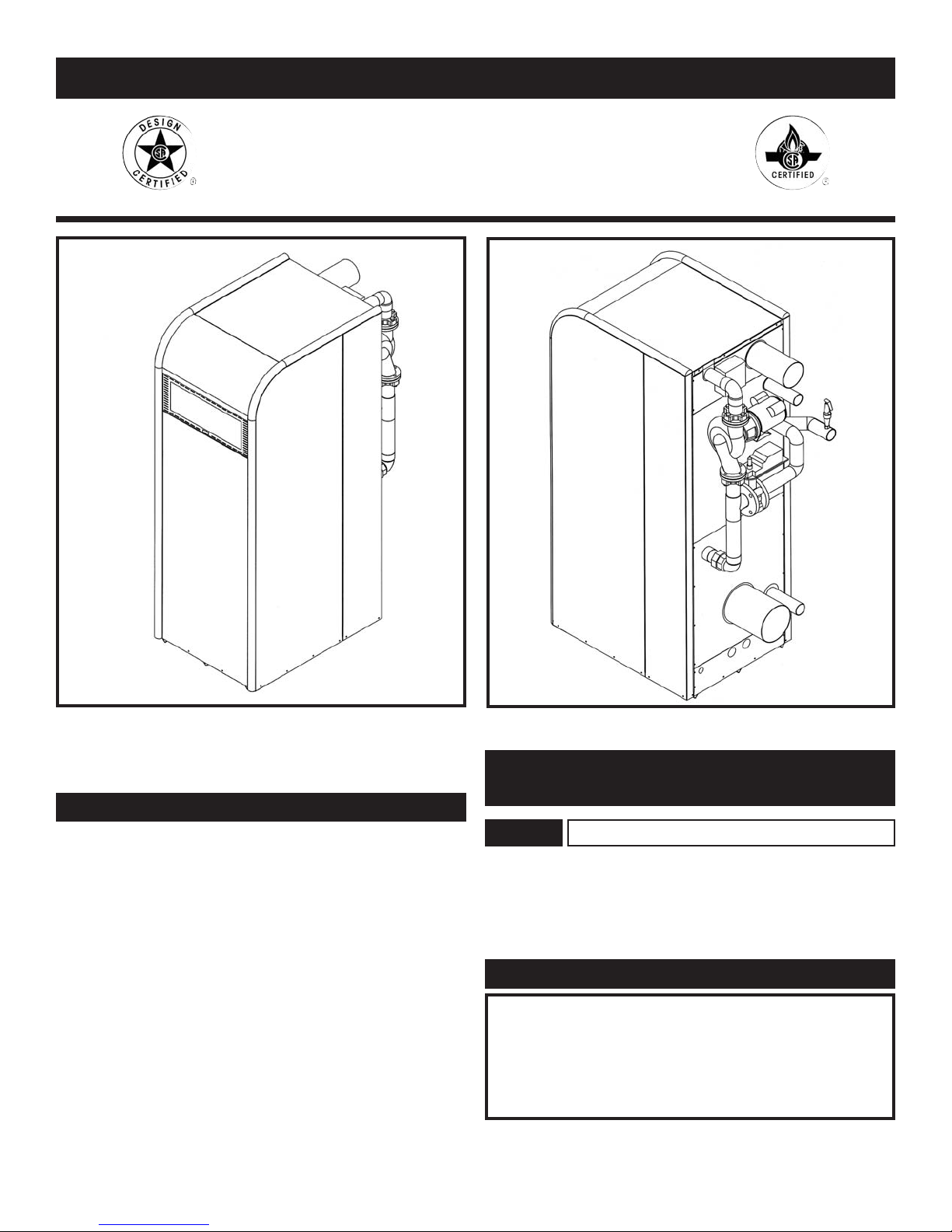
FIG. 1 Front View
FIG. 2 Rear View
Installation and service must be per formed by a qual i fied service
in stall er, service agency or the gas supplier.
Factory warranty (shipped with unit) does not apply to units
improperly installed or improperly operated.
Experience has shown that improper installation or system design,
rather than faulty equipment, is the cause of most operating
problems.
1. Excessive water hardness causing a lime/scale
build-up in the copper tube is not the fault of the
equipment and is not covered under the
manufacturer’s war ran ty. (See Water Treatment and
Water Chemistry)
2. Excessive pitting and erosion on the inside of the
copper tube may be caused by too much water
velocity through the tubes and is not covered by
the man u fac tur er’s warranty (See Boiler Flow Rates
and Temperature Rise for flow requirements).
This manual supplies information for the installation, operation
and ser vic ing of the appliance. It is strong ly recommended that
this manual be re viewed com plete ly before proceeding with an
installation.
WARRANTY
SPECIAL INSTRUCTIONS
TO OWNER
NOTE:
Retain this manual for future reference.
WARNING
IMPROPER INSTALLATION, ADJUSTMENT,
ALTERATION, SERVICE OR MAINTENANCE can
cause injury or property damage. Refer to this manual. For
assistance or additional information, consult a qualified
installer, service agency or the gas supplier.
1

TABLE OF CONTENTS
Warranty .......................................................................... 1
Safety Warnings .............................................................. 3
Codes .......................................................................... 3
Installation Requirements ............................................ 4
Location .................................................................... 4
Clearances ................................................................ 4
Combustion/Ventilation Air Requirements .............. 5
Construction Air Filter .............................................. 7
Venting Systems ............................................................ 8
Category IV Venting ........................................................ 9
Flue Pipe Materials............................................ 9
Installation Guidelines ...................................... 9
Vent Length Requirements ................................10
Drain Tee Installation ........................................10
Vertical Terminations ........................................11
Sidewall Terminations ......................................12
Direct Vent Systems ........................................................13
Air Inlet Pipe Materials ....................................14
Air Inlet Pipe Length Requirements..................14
Vertical Direct Vent ..................................................15
Location Requirements......................................15
Multiple Direct Vent Installations......................16
Horizontal Direct Vent ..............................................16
Location Requirements......................................16
Multiple Direct Vent Installations......................18
Intelli-Vent Systems..................................................18
Materials ............................................................18
Length Requirements ........................................18
Vertical Flue - Sidewall Air ..............................19
Sidewall Flue - Rooftop Air ..............................20
Sidewall Flue - Sidewall Air..............................21
Gas Supply ....................................................................23
Gas Pressures and Piping ..................................23
Manifold Pressure..............................................23
Supply Pressure Measurement ..........................25
Manifold Pressure Measurement ......................26
Water Connections ..........................................................27
Heat Exchangers ..............................................................28
Integral Bypass ................................................................29
Valve and Pump ................................................29
Synchronization ................................................29
Set-up Maximum Flow......................................30
Bypass Operation ..............................................31
Minimum Water Temperatures ..................................31
Flow Switch ....................................................................32
Low Water Cut-Off ..........................................................32
Gas Train..........................................................................32
Relief Valve......................................................................33
Ratio Gas Valve ........................................................33
Diaphragm Gas Valve ..............................................33
Electrical Requirements ..................................................34
Jacket ..........................................................................34
Components and Controls ............................................35
Variable Frequency Drive..................................36
Low Air Pressure Switch ..................................37
Gas Pressure Switches ......................................37
Excel 10 Boiler Interface Controller ................37
Manual Override Control ..................................39
2
Temperature Adjustment....................................39
Command Display ............................................39
Password ....................................................40
Changeable Points ......................................40
Data Points in Display................................41
Status Points — Operation ........................43
Status Points — Alarm ..............................44
Outdoor Reset Function ............................44
Multiple Appliance Installations........................45
Sequencing Options....................................45
E-Bus Connection ......................................46
Temperature Limit Control ................................48
Hot Surface Ignition Control ............................48
Hot Surface Igniter..............................49
Diagnostic Status LED........................49
Operation/Diagnostic Lights and Switches ......50
Burner Assembly ..............................................51
Combustion Air Blower ....................................52
Condensate Management System......................53
Installation and Operation ..................53
Condensate Trap Installation ..............54
Lighting Instructions ....................................................55
Sequence of Operation ..................................................57
Maintenance ............................................................57
Maintenance and Annual Startup..............................58
Vent System ............................................................58
Flame Patterns ..........................................................58
Condensate Testing ..................................................59
Burner Cleaning........................................................59
Heat Exchanger Inspection ......................................61
Lubrication ............................................................62
Combustion Air Measurements ................................62
Freeze Protection ......................................................63
Heating Boiler ............................................................64
Piping ............................................................64
Piping Length and Diameter ....................................65
Integral Pump Limitations ................................65
Boiler Pump Operation......................................65
Primary/Secondary Piping ................................66
Minimum Water Temperatures ..........................66
Three Way Valves..............................................67
Boiler Flow Rates ..............................................67
Placing the Boiler in Operation ........................68
Boiler Temperature Control ..............................69
Water Heater/Domestic Hot Water Supply Boiler ....70
Typical Piping ....................................................70
Set-up Maximum Flow......................................70
Temperature Rise ..............................................71
Water Chemistry ................................................72
Piping Requirements ........................................73
Pump Operation ................................................74
Temperature Adjustment....................................75
Minimum Inlet Temperatures ............................75
Risk of Scald Warnings ....................................76
Relief Valve ......................................................76
Ladder Diagram ............................................................77
Wiring Diagram ............................................................78
Revision Notes ..............................................Back Cover

Upon receiving equipment, check for signs of ship ping damage.
Pay par tic u lar attention to parts ac com pa ny ing the boiler, which
may show signs of being hit or otherwise being mishandled. Verify
total number of pieces shown on packing slip with those actually
re ceived. In case there is damage or a shortage, immedi ate ly notify
carrier.
CHECKING EQUIPMENT
DO NOT
WARNING
Do not use this appliance if any part has been under water.
The possible damage to a flooded appliance can be extensive
and present numerous safety hazards. Any appliance that
has been under water must be replaced.
If the information in this manual is not followed exactly, a
fire or explosion may result causing property damage,
personal injury or loss of life.
This appliance MUST NOT be installed in any location
where gasoline or flammable vapors are likely to be present,
unless the installation is such to eliminate the probable
ignition of gasoline or flammable vapors.
WHAT TO DO IF YOU SMELL GAS
• Do not try to light any appliance.
• Do not touch any electric switch: do not use any phone in
your building.
• Immediately call your gas supplier from a neighbor’s
phone. Follow the gas supplier’s instructions.
• If you cannot reach your gas supplier, call the fire
department.
Installation and service must be performed by a
qualified installer, service agency or the gas
supplier.
OWNER WARNING
The information contained in this manual is intended
for use by qualified professional installers, service
technicians or gas suppliers. Consult your local expert
for proper installation or service procedures.
IMPORTANT
Consult and follow local Building and Fire Regulations and
other Safety Codes that apply to this installation. Contact
the local gas utility company to authorize and inspect all gas
and flue connections.
A gas appliance that draws combustion air from the equipment
room where it is installed must have a supply of fresh air circulating
around it during burner operation for proper gas combustion and
proper venting.
1. Boilers and water heaters are heat producing appliances.
To avoid damage or injury, do not store materials against
the appliance or the vent-air intake system. Use proper care
to avoid unnecessary contact (especially children) with the
appliance and vent-air intake components.
2. Never cover your appliance, lean anything against it, store
trash or debris near it, stand on it or in any way block the
flow of fresh air to your appliance.
3. UNDER NO CIRCUMSTANCES must flammable
materials such as gasoline or paint thinner be used or stored
in the vicinity of this appliance, vent-air intake system or
any location from which fumes could reach the appliance
or vent-air intake system.
The equipment shall be installed in accordance with those
installation regulations in force in the local area where the
installation is to be made. These shall be carefully followed in all
cases. Authorities having ju ris dic tion shall be consulted before
instal la tions are made. In the absence of such requirements, the
installation shall conform to the latest edition of the National Fuel
Gas Code, ANSI Z223.1 and/or CAN/CGA-B149 Installation Code.
Where required by the author i ty having jurisdiction, the in stal la tion
must conform to American Society of Mechanical Engineers Safety
Code for Controls and Safety Devices for Au to mat i cal ly Fired
Boilers, ASME CSD-1. All boilers conform to the latest edi tion of
the ASME Boiler and Pressure Vessel Code, Section IV. Where
required by the authority having ju ris dic tion, the installation must
comply with the CSA International, CAN/CGA-B149 and/or local
codes. This appliance meets the safe lighting performance criteria
with the gas man i fold and control assembly provided, as specified
in the ANSI standards for gas-fired units, ANSI Z21.13.
CODES
WARNING
Should overheating occur or the gas supply fail to shut off,
DO NOT turn off or disconnect the electrical supply to
the pump. Instead, shut off the gas supply at a location
external to the appliance.
WARNING
To minimize the possibility of serious personal injury, fire or
damage to your appliance, never violate the following safety
rules.
3

4
1. Locate the appliance so that if water connections should
leak, water damage will not occur. When such lo ca tions
cannot be avoided, it is recommended that a suitable drain
pan, ad e quate ly drained, be installed under the unit. The pan
must not restrict combustion airflow. Under no
circumstances is the manufacturer to be held responsible for
water damage in connec tion with this unit, or any of its
components.
2. The appliance must be installed so that the ignition
system components are protected from water
(dripping, spraying, etc.) during appliance operation and
service (circulator re place ment, control replacement, etc.).
3. Appliances located in a residential garage and in adjacent
spaces that open to the garage and are not part of the living
space of a dwelling unit must be installed so that all burners
and burner ignition devices have a minimum clearance of
not less than 18" (46cm) above the floor. The appliance
must be located or protected so that it is not subject to
physical damage by a moving vehicle.
4. DO NOT install this appliance in any location where
gasoline or flammable vapors are likely to be present.
5. The appliance must be installed on a level floor.
Combustible floor locations may be used. Maintain re quired
clearances from combustible surfaces.
6. The appliance must not be in stalled on carpet.
7. The appliance must be installed indoors where it
is protected from exposure to wind, rain and
weather.
8. This appliance may condense the products of
combustion when operating at water temperatures
below 130°F (54.4°C). Ensure that the appliance is
located near an acceptable drain where the
condensate from the heat exchanger and venting
system may be properly col lect ed, neutralized and
disposed.
INSTALLATION PROCEDURE
LOCATION OF UNIT
TABLE - A
Clearances from
Combustible Construction:
Right Side - 0"
Rear - 9" (23 cm) (Minimum 24" (0.61 m) suggested for
service to pump and components)
Left Side - 0"
Front - ALCOVE* (Minimum 24" (0.61 m) suggested for
service)
Flue - 1" (25.4 mm)
Hot Water Pipes - 1" (25.4 mm)
*An ALCOVE is a closet without a door.
RECOMMENDED SERVICE CLEARANCES
FIG. 3 Recommended Service Clearances - Front
FIG. 4 Recommended Service Clearances - Rear
5
NOTE
Clearances from combustible construction are noted on the
appliance rating plate.
Maintain minimum specified clearances for adequate operation.
All in stal la tions must allow sufficient space for servicing the vent
connections, water pipe connections, integral circulating pump,
bypass piping and other auxiliary equipment, as well as the
appliance. The clearance labels on each appliance note the same
service and combustible clearance requirements as shown in the
clearances from combustion construction table.
Multiple appliances may be installed in a modular boiler or water
heater in stal la tion. Multiple appliances may be installed side by
side with no clear ance between adjacent appliances because this
appliance is approved for zero clearance from combustible sur fac es and no service access is required from the sides.
Consult the venting section of the manual for specific installation
in struc tions for the appropriate type of venting system that you will
be using. Direct Vent and Intelli-Vent venting systems require
installation with Category IV flue pipe, sealed air inlet pipe and air
inlet caps, which must meet the manufacturer’s specifications.
COMBUSTION AND VENTILATION
AIR REQUIREMENTS FOR
APPLIANCES DRAWING AIR FROM
THE EQUIPMENT ROOM
Provisions for combustion and ven ti la tion air must be in accordance
with Section 5.3, Air for Combustion and Ventilation, of the latest
edition of the National Fuel Gas Code, ANSI Z223.1, in Canada,
the latest edition of CAN/CGA Standard B149 Installation Code
for Gas Burning Appliances and Equip ment, or applicable
provisions of the local building codes.
The equipment room MUST be provided with properly sized
openings to assure adequate combustion air and proper ventilation
when the unit is installed with a basic Category IV venting system.
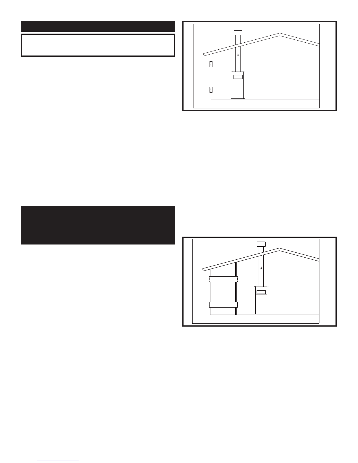
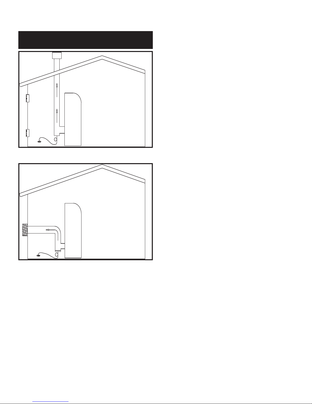
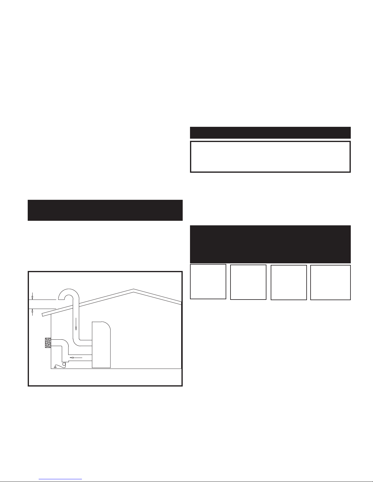
FIG. 5 Combustion Air Direct from Outside
1. If air is taken directly from outside the building
with no duct, provide two permanent openings:
a. Combustion air opening, with a min i mum free
area of one square inch per 4000 Btu input
(5.5 cm
2
per kW). This opening must be located
within 12" (30cm) of the bottom of the
enclosure.
b. Ventilation air opening, with a minimum free
area of one square inch per 4000 Btu input
(5.5 cm
2
per kW). This opening must be located
within 12" (30 cm) of the top of the enclosure.
FIG. 6 Combustion Air Through Ducts
2. If combustion and ventilation air is taken from the outdoors
using a duct to deliver the air to the mechanical room, each of
the two openings should be sized based on a minimum free
area of one square inch per 2000 Btu (11 cm2 per kW) of input.
6
TABLE - B
Minimum Recommended Combustion
AIR SUPPLY TO MECHANICAL ROOM
Btu/hr
Input
1,500,000
375 in2(2419 cm2)
425 in2(2742 cm2)
500 in2(3226 cm2)
500 in2(3226 cm2)
567 in2(3658 cm2)
667 in2(4303 cm2)
1,500 in2(9,677 cm2)
1,700 in2(10,968 cm2)
2,000 in2(12,903 cm2)
1,700,000
2,000,000
Outside Air*
2 - Openings
Outside Air*
1 - Opening
Inside Air
2 - Openings
*Outside air openings shall directly communicate with the outdoors. When combustion air is drawn from the out side through a duct,
the net free area of each of the two openings must have twice (2 times) the free area required for Outside Air/2 Openings. The above
requirements are for the boiler only, additional gas fired appliances in the equipment room will require an increase in the net free area
to supply adequate combustion air for all appliances. Combustion air requirements are based on the latest edition of the National Fuel
Gas Code, ANSI Z223.1, in Canada refer to the latest edition of CAN/CGA B149. Check all local code re quire ments for combustion
air.
Combustion Air Source
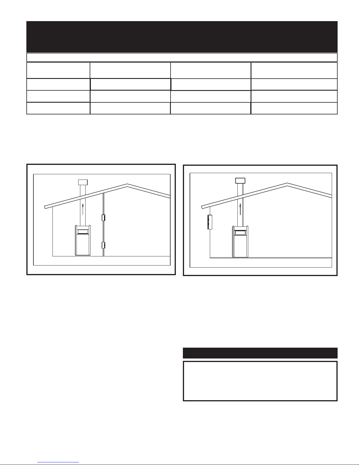
FIG. 7 Combustion Air from Interior Space
FIG 8 Combustion Air from Outside - Single Opening
3. If air is taken from another interior space, each of the two
openings specified above should have a net free area of one
square inch for each 1000 Btu (22 cm
2
per kW) of input,
but not less than 100 square inches (645 cm2).
4. If a single combustion air open ing is provided to
bring combustion air in directly from the outdoors,
the opening must be sized based on a minimum
free area of one square inch per 3000 Btu (7 cm
2
per kW). This opening must be located within 12"
(30 cm) of the top of the enclosure.
CAUTION
Under no circumstances should the mechanical room ever
be under a negative pressure. Particular care should be taken
where exhaust fans, attic fans, clothes dryers, compressors,
air handling units, etc., may take away air from the unit.
7
All dimensions based on net free area in square inches. Metal
louvers or screens reduce the free area of a com bus tion air opening
a minimum of ap prox i mate ly 25%. Check with louver
manufacturers for exact net free area of louvers. Where two
openings are provided, one must be within 12" (30 cm) of the
ceiling and one must be within 12" (30 cm) of the floor of the
mechanical room. Each opening must have net free area as
specified in Table - B. Single openings shall commence within 12"
(30 cm) of the ceiling.
The combustion air supply must be com plete ly free of any
flammable vapors that may ignite or chemical fumes which may
be corrosive to the appliance. Common corrosive chemical fumes
which must be avoided are fluorocarbons and other halogenated
compounds, most commonly present as refrigerants or solvents,
such as Freon, trichlorethylene, perchlorethylene, chlorine, etc.
These chemicals, when burned, form acids which quickly attack
the heat exchanger finned tubes, headers, flue collectors, and the
vent system. The result is improper combustion and a nonwarrantable, premature appliance failure.
These chemicals, when burned form acids which quickly attack the
boiler tubes, tube sheets, flue collectors, and the ap pli ance stack.
The result is improper combustion and a non-warrantable, pre ma ture failure of the appliance.
EXHAUST FANS: Any fan or equipment which exhausts air from
the equipment room may deplete the combustion air supply and/or
cause a downdraft in the venting system. Spillage of flue prod ucts
from the venting system into an occupied living space can cause a
very hazardous condition that must be im me di ate ly corrected. If a
fan is used to supply combustion air to the equipment room, the
installer must make sure that it does not cause drafts that could lead
to nuisance operational problems with the appliance.
A construction air filter is installed on the ap pli ance as shipped.
The filter assembly is installed on the combustion air inlet located
at the rear of the appliance. The filter assembly slips over the air
inlet collar and is secured in place with the clamp provided with
the filter. If limited space is available at the rear of the appliance,
field supplied elbows may be used to mount the filter in the
alternate positions shown in the illustration. This filter is For
Temporary Use Only on an appliance that must be operated for
temporary heat or hot water when a building is under construction.
The filter will provide a temporary means to remove airborne dust,
dirt and particulate matter generated by construction. The filter
prevents airborne particulate contaminants from being drawn into
the burner with the combustion air. The filter can be cleaned
routinely during construction if necessary. Remove the filter to
clean. Wash the filter with water. A flow of water from the inside
to the outside should remove most particle matter. Allow the filter
to dry before reinstalling. Unfiltered com bus tion air from a
construction site can contain con tam i nants that will collect in the
burner reducing the firing rate. A burner that becomes clogged with
airborne particulate contaminants must be removed and cleaned to
restore proper operation to the burner. Sustained operation of an
appliance with a clogged burner may result in nuisance operational
prob lems, bad combustion and non-warrantable component failures.
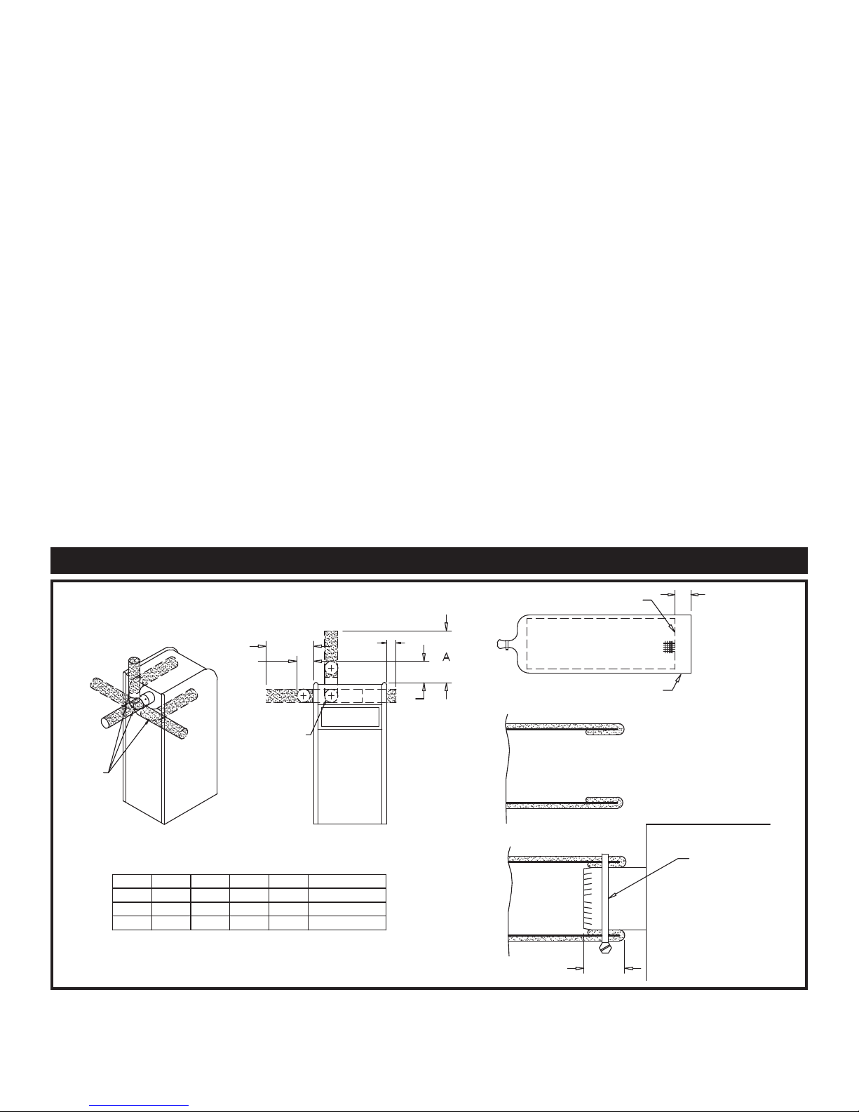
CONSTRUCTION AIR FILTER
FIG. 9 Construction Air Filter
ELBOW(S)
NOT
PROVIDED
REAR
MODEL
2.0 19.750
1.7
1.5
A
19.250
18.750
D
CABINET AIR
INLET OPENING
B
12.250 4.875
10.750
9.250
C
4.375
3.875
E
FRONT
D E REAR
15.000
9.000
7.500
14.500
6.000
14.000
C
B
24.000
24.000
24.000
EDGE OF SCREEN
MEDIA OVERLAP
2"
2"
FOLD OVERLAP AROUND
EDGE OF SCREEN AS
SHOWN.
BAND CLAMP
PUSH FILTER ONTO AIR
INLET AND FASTEN WITH
CLAMP AS SHOWN.

8
The construction air filter MUST be removed from the
appliance’s air inlet before the appliance is placed in normal
operation. Once the construction air filter is removed, ensure that
either the equipment room is supplied with combustion air from
properly sized combustion and ventilation air openings or a
combustion air duct from a Direct Vent or Intelli-Vent system is
connected to the appliance. The optional Direct Vent and
Intelli-Vent venting sys tems have specific requirements for a
special com bus tion air duct from the outside that is directly
connect ed to the appliance. See the requirements for this
combus tion air duct in the vent ing section for each spe cial ized
vent system.
CONSTRUCTION AIR FILTER KITS
TABLE - C
Input Construction
Btu/hr Air Filter Kit
1,500,000
________________________
1,700,000
________________________
2,000,000
KIT4000
________________________
KIT4001
________________________
KIT4002
VENTING
Vent System Options
This appliance has three venting system options. They are: (A)
Category IV Venting system with vertical roof top termination or
sidewall termination of the flue and combustion air supplied from
the mechanical room. (B) Direct Vent with a Category IV flue
and a separate combustion air pipe to the outdoors. The Direct
Vent system ter mi nates both the flue and air inlet in the same
pressure zone. The flue out let and combustion air intake may
ter mi nate on either the sidewall or with a rooftop termination.
(C) Intelli-Vent with a Category IV flue and a separate
combustion air pipe to the outdoors.The Intelli-Vent system
terminates the flue and the combustion air inlet pipe in different
pressure zones. The Intelli-Vent system may terminate the flue on
the roof top and combustion air intake on the sidewall, the flue
on the sidewall and combustion air from the rooftop or the flue
on the sidewall and combustion air from a different sidewall. All
appliances are shipped from the factory equipped for Category
IV venting. The optional Direct Vent and Intelli-Vent venting
systems will require the installation of specific vent kits and
venting materials. The following is a detailed explanation of the
installation requirements for each venting system, components
used and part numbers of vent kits for each model.
General
Vent installations for connection to gas vents or chimneys must be
in ac cor dance with Part 7, “Venting of Equip ment,” of the latest
edition of the National Fuel Gas Code, ANSI Z223.1, in Canada,
the latest edition of CAN/CGA Stan dard B149 Installation Codes
for Gas Burning Appliances and Equipment or applicable
provisions of the local building codes.
Adequate combustion and ventilation air must be supplied to the
equipment room in accordance with the latest edition of the
National Fuel Gas Code, ANSI Z223.1, in Canada, the latest edition
of CAN/CGA Standard B149 Installation Codes for Gas Burning
Appliances and Equip ment, or applicable provisions of the local
building codes.
The distance of the vent terminal from adjacent buildings, windows
that open and building openings MUST comply with the latest
edition of the National Fuel Gas Code, ANSI Z223.1, in Canada,
the latest edition of CAN/CGA Standard B149 Installation Code
for Gas Burning Ap pli anc es and Equipment.
Vent connection is made directly to the flue outlet opening on the
back of the unit. The connection from the ap pli ance vent to the
stack must be made as direct as possible.
IMPORTANT
Examine the venting system at least once a year. Check all
joints and vent pipe connections for tightness. Also, check
for corrosion or deterioration. Immediately correct any problems observed in the venting system.
TABLE - D
The Category IV Flue Pipe Sizes
Input Btu/hr Flue Size
1,500,000
________________________
1,700,000
________________________
2,000,000
6"
________________________
7"
_______________________
8"
9
Category IV Venting
A CATEGORY IV POSITIVE
PRESSURE VENTING SYSTEM
FIG. 10 Basic Category IV Venting - Vertical
FIG. 11 Basic Category IV Venting - Horizontal
A Category IV venting system for the flue products is required on
all models of this appliance. A Category IV vent ing system
operates with a positive pressure in the vent. This positive pressure
is generated by the internal combustion air blower which operates
the combustion process and also ex hausts the flue products from
the build ing. The Category IV flue from this appliance can NOT
be combined with the vent from any other appliance. The Category
IV flues from multiple ap pli anc es can NOT be combined into a
common vent. The Category IV flue from this appliance must be
a dedicated stack. The flue from this Category IV ap pli ance must
have all vent joints and seams sealed gas-tight. A Category IV
vent system has specific vent material and installation requirements.
The flue products in the vent system may be cooled below their
dew point and form condensate in the flue. The
ma te ri als used for a Category IV vent must be resistant to any
corrosive damage from flue gas condensate. The flue from a
Category IV vent system must have a condensate drain with
provisions to properly collect and dispose of any condensate that
may occur in the vent ing system.
Category IV Flue Pipe Materials
Select venting material from the fol low ing specified vent
distributors:
Heat-Fab Inc. Saf-T CI Vent with AL29-4C stainless steel
(Call 1-800-772-0739 for nearest distributor)
Protech Systems Inc. Fas N Seal Vent with AL29-4C stainless
steel (Call 1-800-766-3473 for nearest distributor)
Z-Flex Z-Vent with AL29-4C stainless steel
(Call 1-800-654-5600 for nearest distributor)
Or other listed Category IV vent sys tems suitable for a condensing,
pos i tive pressure gas fired appliance.
Venting Guidelines for a Category IV Vent
The connection from the appliance vent to the stack or vent
termination out side the building MUST be made with listed
Category IV vent system and must be direct as possible with no
reduction in diameter. The Category IV vent and accessories, such
as firestop spacers, thimbles, caps, etc., MUST be installed in
accordance with the vent manufacturers instructions. The vent
connector and firestop must provide correct spacing to combustible
surfaces and seal to the vent connector on the upper and lower sides
of each floor or ceiling through which the vent connector passes.
In a typical installation, each appliance must have a dedicated
Category IV flue with no other appliance interconnected to any
part of the dedicated flue. Each appliance MUST connect to the
dedicated flue stack using a properly sealed vent adapter provided
by the vent manufacturer. The flues from multiple Intelli-Fin
appliances may only be combined when using an engineered vent
system incorporating an induced draft fan to ensure that flue
products will be properly exhausted from the building at all times.
Failure to use a properly sized induced draft fan on a combined vent
installation may result in a hazardous condition where flue gases
spill into an occupied living space. Consult the induced draft fan
manufacturer to size the induced draft fan and to determine the
diameter of the common vent pipe required for a combined vent
installation.
10
Any vent materials specified must be listed by a nationally
recognized test agency for use as a Category IV vent material.
The venting system must be planned so as to avoid possible
contact with con cealed plumbing or electrical wiring inside walls,
floors or ceilings. Locate the appliance as close as pos si ble to a
chimney or gas vent.
There shall be no reductions in vent diameter.
Horizontal portions of the venting system shall be supported to
prevent sagging. Horizontal runs should slope upwards not less
than 1/4 inch per foot (21 mm/m) from the drain tee installed in
the flue to the vertical portion of the flue or to the vent terminal
on sidewall venting installations. This ensures proper removal of
any con den sate that may form in the flue. Follow the installation
instructions from the vent material manufacturer.
Do not use an existing chimney as a raceway if another appliance
or fire place is vented through the chimney. The weight of the
venting system must not rest on the unit. Adequate support of the
venting system must be provided in compliance with local codes
and other applicable codes. All con nec tions should be secured
and sealed per the vent manufacturers specifications.
Vent connectors serving appliances vented by natural draft shall
not be connected to any portion of the Cat e go ry IV positive
pressure vent system used by this appliance. Connection of a
negative draft flue into the positive pressure stack from this
appliance may cause flue products to be discharged into an
occupied living space causing serious health injury.
When a Category IV vent system is dis con nect ed for any reason,
the flue must be reassembled and resealed according to the vent
manufacturer’s in struc tions.
The installed length of the Category IV flue from the appliance
to the point of termination, outside of the building, must not
exceed a maximum of 100 equiv a lent feet (30.5 m) in length.
Subtract 5 feet (1.5 m) of equivalent length for each 90° elbow
installed in the vent. Subtract 2 1/2 feet (0.7 m) of equivalent
length for each 45° elbow installed in the vent.
The flue may terminate either ver ti cal ly at the roof top or
horizontally on a sidewall. See the information about the specific
vent termination location for recommended location and
clearances.
General Category IV Vent Termination Clearances
The vent cap should have a minimum clearance of 4 feet (1.2 m)
horizontally from and in no case above or below, unless a 4 foot
(1.2 m) horizontal dis tance is maintained from electric meters,
gas meters, regulators and relief equipment.
The venting system shall terminate at least 3 feet (0.9 m) above
any forced air inlet within 10 feet (3.05 m).
The venting system shall terminate at least 4 feet (1.2 m) below,
4 feet (1.2 m) horizontally from, or 1 foot (30 cm) above any
door, window or grav i ty air inlet into any building.
Do not terminate the vent in a window well, stairwell, alcove,
courtyard or other recessed area. The vent cannot terminate
below grade. The bottom of the vent terminal shall be located at
least 12 inches (30 cm) above grade and above normal snow levels.
To avoid a blocked flue condition, keep the vent cap clear of snow,
ice, leaves, debris, etc.
Flue gases from this appliance may contain large amounts of water
vapor that will form a white plume in winter. Plume could obstruct
a window view.
Flue gas condensate can freeze on ex te ri or surfaces or on the vent
cap. Fro zen condensate on the vent cap can result in a blocked flue
condition. Flue gas condensate can cause discoloration of exterior
building surfaces. Adjacent brick or masonry surfaces should be
protected with a rust re sis tant sheet metal plate.
The manufacturer shall NOT be held liable for any personal injury
or prop er ty damage due to ice formation or the dislodging of ice
from the vent system or the vent termination.
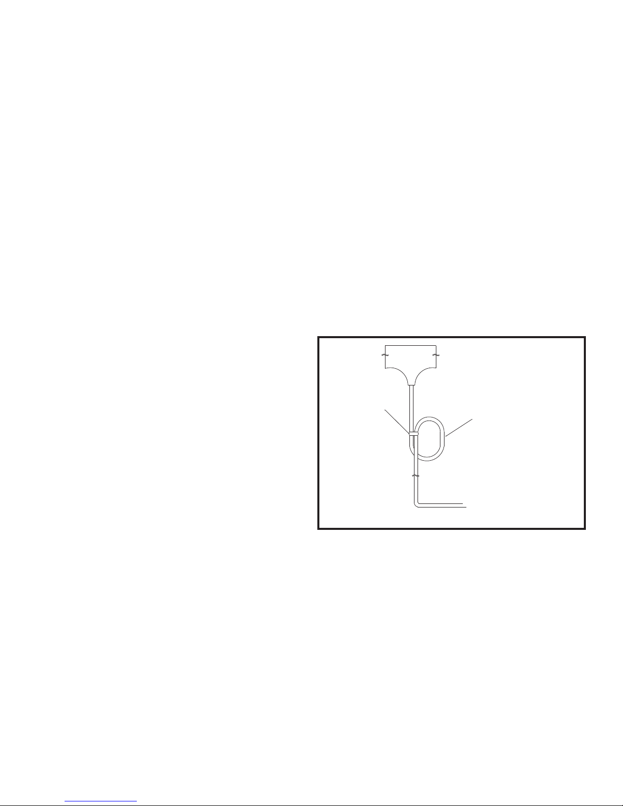
Drain Tee Installation
WIRE TIE
4" Ø
CIRCULAR TRAP
TO SUITABLE DRAIN
FIG. 12 Drain Tee
A drain tee MUST be installed in the Category IV vent pipe to
collect and dispose of any condensate that may occur in the vent
system. The drain tee should be installed at the point where the
flue turns vertical for a roof top termination or as one of the first
fittings in a horizontal flue that will terminate on a sidewall. Ensure
that horizontal portions of the vent are properly sloped to allow
condensate to be evacuated at the drain tee. See the typical vent
installation drawings. Plastic drain tubing, sized per the vent
manufacturer’s instructions, shall be provided as a drain line from

11
the tee. The drain tubing must have a trap provided by a 4"
(10.2 cm)-diameter circular trap loop in the drain tubing. Prime
the trap loop by pouring a small quantity of water into the drain
hose before assembly to the vent. Secure the trap loop in position
with nylon wire ties. Use caution not to collapse or restrict the
condensate drain line with the nylon wire ties. The con den sate
drain must be routed to the con den sate neutralization system or a
suitable drain for disposal of con den sate that may occur in the
Category IV vent system. Refer to the condensate drain
installation instructions as supplied by the manufacturer of the vent
material. Ensure that the drain from the condensate tee is not
exposed to freezing temperatures. See “Freeze Protection” for
more information.
MASONRY CHIMNEY
INSTALLATIONS
A standard masonry chimney must NOT be used to vent the
products of combustion from the flue of a Category IV,
pos i tive pressure appliance. If a masonry chimney is to be used,
the chimney MUST use a sealed, metallic, corrosion
re sis tant liner system to vent flue products from this high
efficiency appliance. Sealed, metallic, corrosion resistant liner
systems (single wall, double-wall, or flexible or rigid metallic
liners) must be rated for use with a high efficiency Category IV,
positive pressure vent system. Corrosion re sis tant chimney liner
systems are typ i cal ly made from a high grade of cor ro sion resistant
stainless steel such as AL 29-4C. The corrosion resistant liner must
be properly sized and fully sealed throughout the entire length if
the flue is contained within the masonry chimney. Both the top and
the bottom of the masonry chimney must be capped and sealed to
provide a dead air space around the sealed corrosion resistant
metallic liner. Consult with local code officials to determine code
re quire ments or the advisability of using a masonry chimney
with a sealed cor ro sion resistant liner system.
CAUTION
Venting of a high efficiency Category IV appliance into a
masonry chimney without a sealed stainless steel liner can
result in operational and safety problems. Any breaks, leaks
or damage to the masonry flue/tile will allow spillage of the
positive pressure flue products from the chimney. These
flue products can easily escape into an occupied living
space causing a health hazard. If there is any doubt about
the condition of a masonry chimney, or its acceptability for
use after inser tion of a corrosion resistant liner system,
consult with local code officials.
VERTICAL VENTING
TERMINATIONS
Follow all General Category IV Vent Termination Clearances.
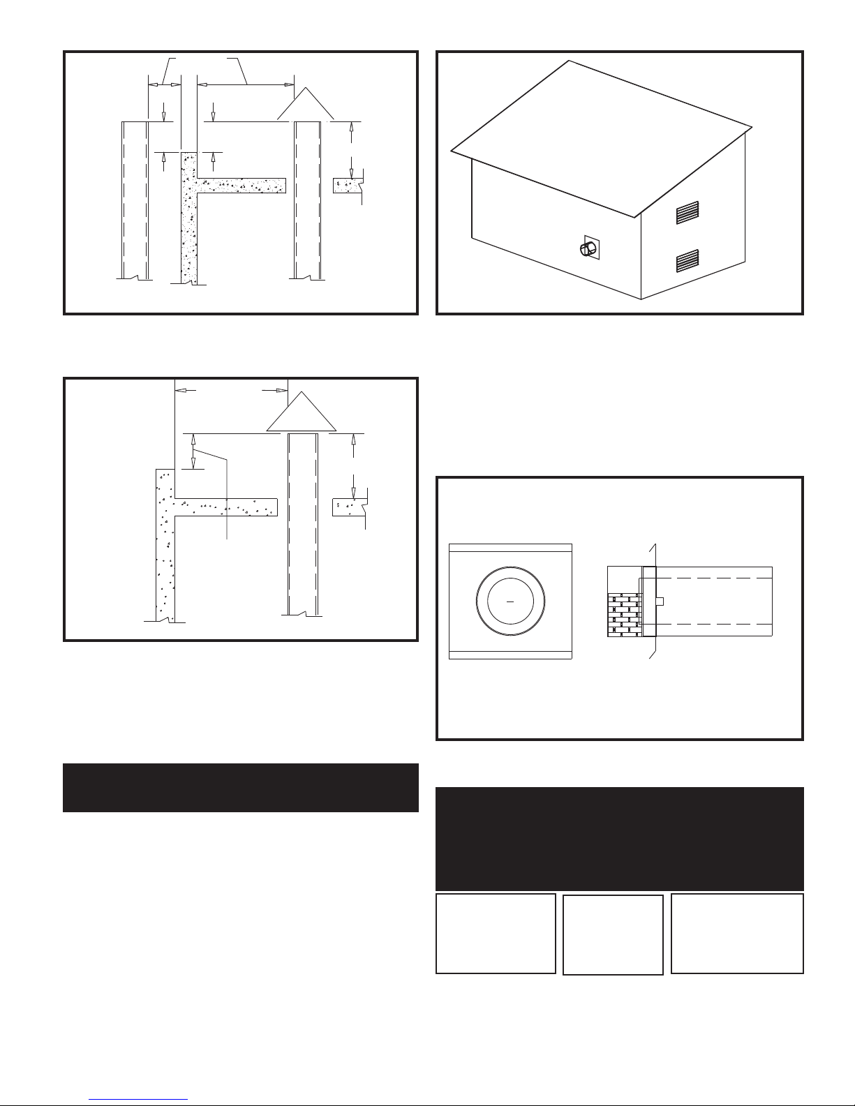
RIDGE
CHIMNEY
3' MIN
2' MIN
10' OR LESS
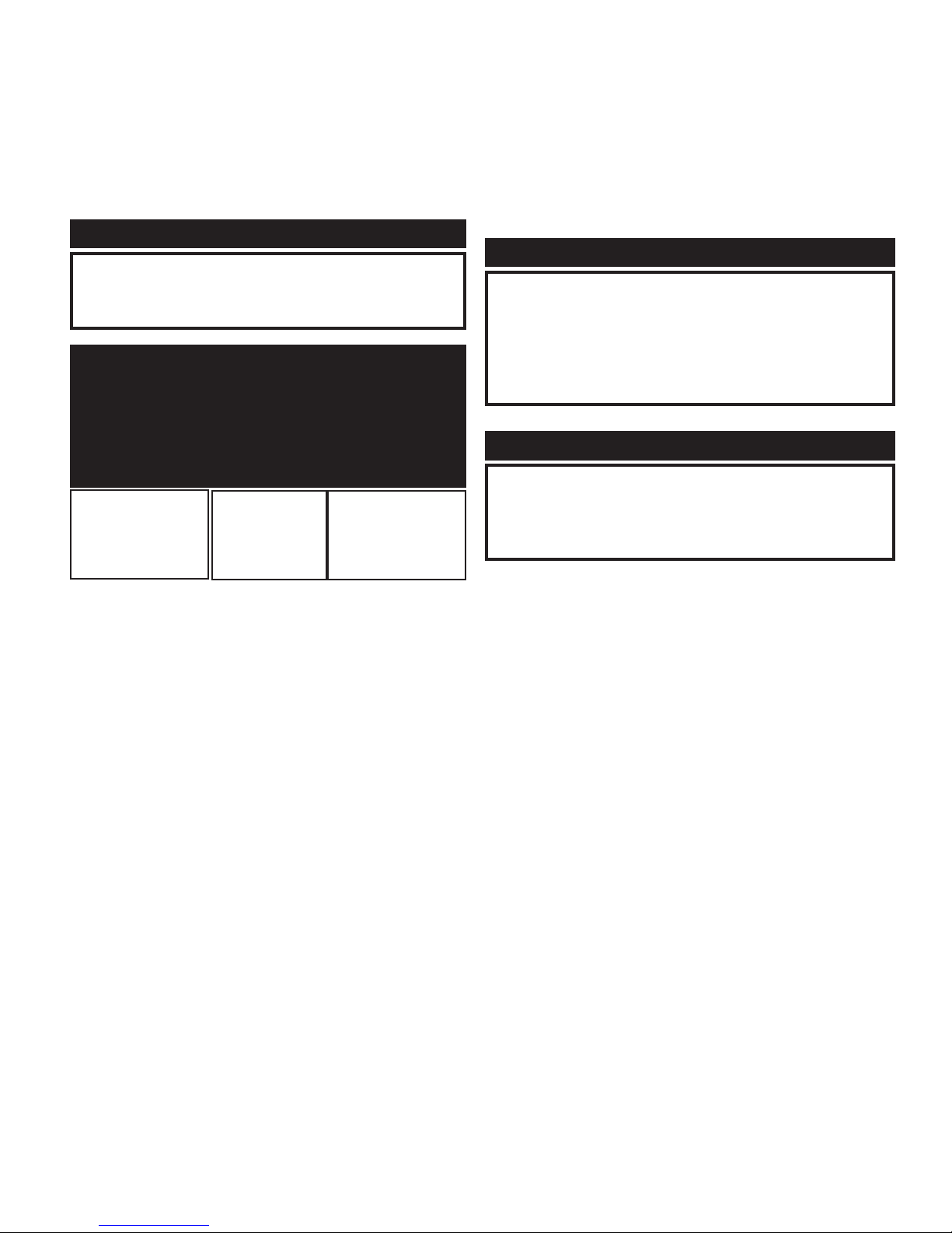
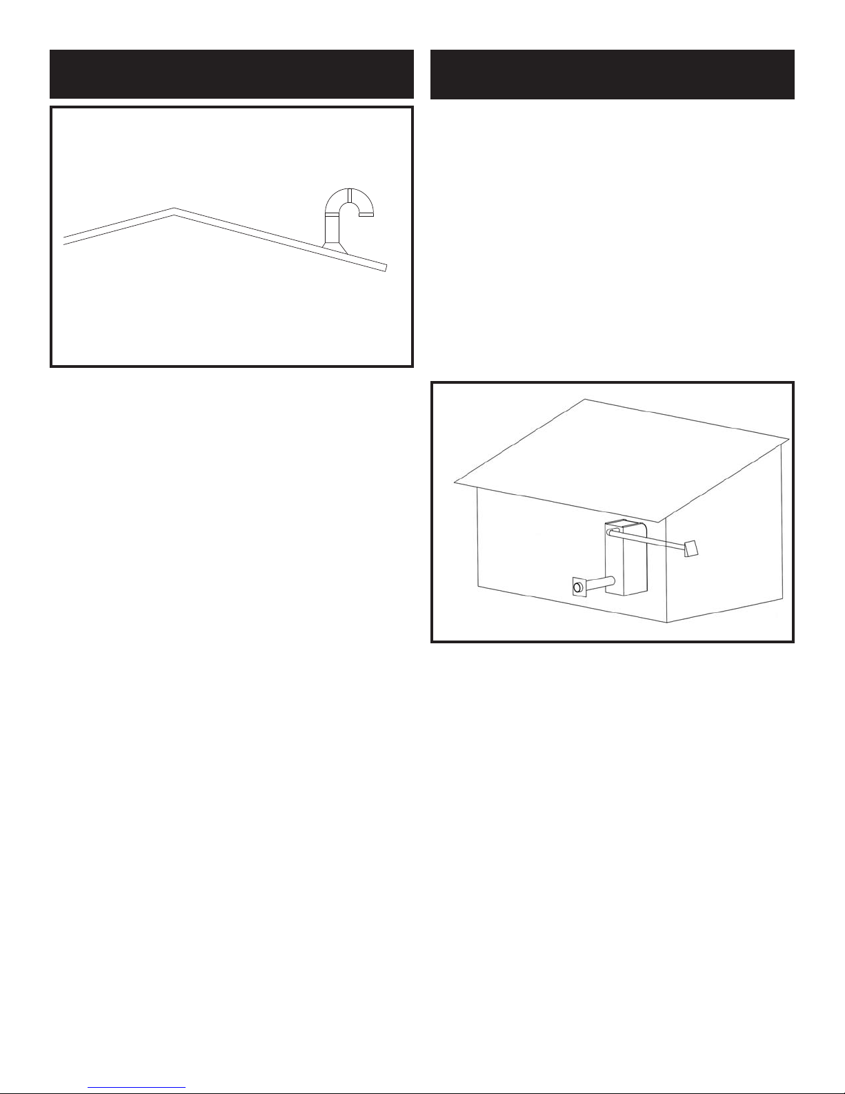
FIG. 13 Vent Termination from Peaked Roof - 10 Feet or Less
from Ridge
FIG. 14 Vent Termination from Peaked Roof - 10 Feet or
More from Ridge
The vent terminal should be vertical and exhaust outside the building at least 2 feet (0.61 m) above the highest point of the roof within
a 10 foot (3.05 m) radius of the termination.
The vertical termination must be a minimum of 3 feet (0.91 m)
above the point of exit.
MORE THAN 10'
10'
RIDGE
2' MIN
3' MIN
CHIMNEY
12
10' OR LESS
FIG. 15 Vent Termination from Flat Roof - 10 Feet or
Less from Parapet Wall
FIG. 16 Vent Termination from Flat Roof - 10 Feet or
More from Parapet Wall
A vertical termination less than 10 feet (3.05 m) from a parapet
wall must be a minimum of 2 feet (0.61 m) higher than the
parapet wall.
SIDEWALL VENTING
TERMINATIONS
This venting system uses the ap pli ance’s internal combustion air
blower to force the flue products out of a horizontally-terminated
flue. This blower generates a positive pres sure in the flue.
Combustion air is drawn from the equipment room (see
Combustion and Ventilation Air Re quire ments) unless the
appliance is equipped with an optional Direct Vent or Intelli-Vent
System.
FIG. 17 Sidewall Venting Installation
The connection from the appliance flue outlet to the sidewall vent
cap MUST be made with listed type Category IV vent materials
and accessories. The in stall er must supply suitable vent pipe
material. The sidewall vent cap is available from the appliance
manufacturer as a vent kit.
FIG. 18 Sidewall Vent Cap
TABLE - E
Sidewall Vent Cap Kits
Sidewall Vent
Input Btu/hr Flue Size Cap Kit
1,500,000
________________
1,700,000
________________
2,000,000
6"
_____________
7"
_____________
8"
SVK3026
_________________
SVK3027
_________________
SVK3028
The sidewall vent cap kit includes the wall penetration assembly
and the dis charge screen assembly. All required Category IV vent
pipe and fittings must be purchased locally.
WALL OR
PARAPET
2' MIN
3' MIN
CHIMNEY
2' MIN
CHIMNEY
10' OR MORE
3' MIN
NOTE: NO HEIGHT
ABOVE PARAPET
REQUIRED WHEN
WALL OR
PARAPET
DISTANCE FOR
WALLS OR PARAPETS
IS MORE THAN 10'>
CHIMNEY
13
The installed sidewall vent cap assembly may be paint ed to match
the exterior color. The opening through the wall for instal la tion of
the sidewall vent cap must provide an air space clearance of
2 inches (5.1 cm) around the flue pipe. The diameter of the opening
for installation of the sidewall cap will be 4 inches (10.2 cm) larger
(minimum) than the nominal diameter of the in stalled vent pipe to
the sidewall cap.
The sidewall cap is installed from the outside and mounted to the
wall with four screws or wall anchors. Seal under the screw heads
with caulking. Install the screen assembly using the stainless steel
screws provided in the kit. Install the Category IV vent pipe from
the appliance to the vent cap. The installed vent pipe must protrude
at least 2 inches (5.1 cm) into the screen area beyond the thimble
portion of the sidewall cap assembly. See detailed instructions
packed with the sidewall vent kit.
Follow all requirements in the General Category IV Venting
sections for vent ing flue products to the outdoors. See the
Combustion and Ventilation Air Requirements section to ensure
that adequate combustion and ventilation air is supplied to the
equipment room. All other general installation requirements must
be followed.
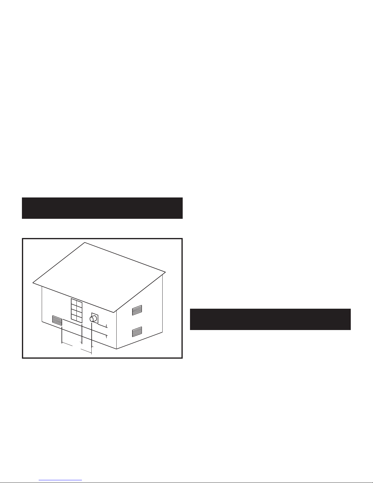
LOCATION OF A SIDEWALL
VENT TERMINATION
Follow all General Category IV Vent Termination Clearances.
3' MIN.
4' MIN.
10' MIN.
HORIZONTALLY
FIG. 19 Sidewall Venting Installation with Clearances from
Vent Cap
The vent cap shall terminate at least 3 feet (0.91 m) above any
forced air inlet within 10 feet (3.05 m) horizontally.
The vent cap MUST NOT terminate below a forced air intake at
any distance.
The vent shall terminate at least 4 feet (1.22 m) below, 4 feet
(1.22 m) horizontally from or 1 foot (0.30 m) above and 2 feet (0.60
m) horizontally from any door, window or gravity air inlet to the
building.
The sidewall vent termination must be at least 8 feet (2.4 m)
horizontally from any combustion air intake located above the
sidewall termination cap.
Do not terminate the vent in a window well, stairwell, alcove,
courtyard or other recessed area. The vent cannot terminate below
grade.
The vent shall not terminate directly above a public walkway due
to the nor mal formation of water vapor in the combustion process.
Horizontal ter mi na tions must not be located over areas of
pedestrian or vehicular traffic.
The vent system shall terminate at least 1 foot (0.30 m) above
grade, above normal snow levels and at least 7 feet (2.13 m) above
grade when located ad ja cent to public walkways.
The vent terminal shall not be in stalled closer than 3 feet
(0.91 m) from an inside corner of an L-shaped struc ture.
The vent cap should have a minimum clearance of 4 feet
(1.22 m) hor i zon tal ly from and in no case above or below, unless
a 4-foot (1.22 m) hor i zon tal distance is maintained from elec tric
meters, gas meters, regulators and relief equipment.
Flue gas condensate can freeze on ex te ri or walls or on the vent
cap. Frozen condensate on the vent cap can result in a blocked
flue condition. Some discoloration to exterior building surfaces
can be expected. Adjacent brick or masonry surfaces should be
protected with a rust resistant sheet metal plate.
The sidewall vent system must use the sidewall vent cap kit
provided by the appliance manufacturer for installation on a
sidewall termination.
The sidewall vent cap MUST be purchased as a kit from the
appliance man u fac tur er to ensure proper operation. Lo cal ly
purchased or fabricated sidewall vent caps should not be used.
DIRECT VENT AND
INTELLI-VENT SYSTEMS
Direct Vent and Intelli-Vent Systems are installed with a Category
IV flue and a separate combustion air pipe to the outdoors. The
Direct Vent System terminates both the flue and combustion air
inlet in the same pressure zone. The Intelli-Vent System terminates
the flue and combustion air inlet in dif fer ent pressure zones. The
flue outlet and combustion air intake may terminate with either a
sidewall or a rooftop termination.
Follow all requirements in the General Category IV Venting
sections for proper installation and venting of flue products
vertically or horizontally to the outdoors. All other general
in stal la tion requirements must be fol lowed.
The Direct Vent and Intelli-Vent Sys tems require the installation of
an additional pipe to supply combustion air from outdoors directly
to the ap pli ance.
14
In cold climates, the use of type “B” double wall vent pipe or an
insulated single wall pipe for combustion air is recommended to
help prevent moisture in the cool incoming air from condensing
and leaking from the inlet pipe.
Termination point for the flue products must follow the clearance
requirements in the Vertical or Horizontal Vent Termination
sections of the Category IV Venting.
CAUTION
Appliances that are shut down or will not operate may
experience freezing due to convective airflow in the air
inlet pipe connected to the appliance.
TABLE - F
Direct Vent and Intelli-Vent Flue
and Air Inlet Pipe Sizes
Air Inlet
Input Btu/hr Flue Size Pipe Size
1,500,000
________________
1,700,000
________________
2,000,000
6"
______________
7"
_____________
8"
6"
________________
7"*
________________
8"
*Piping from the appliance to the air inlet cap may be either 7"
or 8". An 8" diameter sidewall air inlet cap is provided in the
vent kit.
Length of Air Inlet Pipe
The maximum total length of the sidewall or vertical roof top
combus tion air inlet pipe as installed from the appliance to the air
inlet cap must not exceed 100 equivalent feet (30.5 m) in length.
Subtract 5 feet (1.52 m) of equivalent length for each 90° elbow
installed in the air inlet pipe system. Subtract 2 1/2 feet (0.7 m)
of equiv a lent length for each 45° elbow in stalled in the air inlet
pipe system.
Do not exceed limits for the combustion air inlet piping lengths.
Air Inlet Pipe Materials
The air inlet pipe(s) must be sealed. Choose acceptable
combustion air inlet pipe materials from those specified in this
section.
Select air inlet pipe material from the following specified
materials:
• PVC, CPVC or ABS (6", 7"or 8" I.D.)*.
• Dryer Vent or Sealed Flexible Duct (not recommended
for roof top air inlet).
• Galvanized steel vent pipe with joints and seams
sealed as specified below.
• Type “B” double wall vent with joints and seams
sealed as specified below.
* Plastic pipe may require an adapter (not provided) to transition
between the air inlet connection on the ap pli ance and the plastic air
inlet pipe.
WARNING
Using vent or air intake ma te ri als other than those specified,
fail ure to properly seal all seams and joints or failure to
follow vent pipe manufacturer’s instructions can result in
personal injury, death or property damage. Mixing of
venting materials will void the warranty and cer ti fi ca tion
of the appliance.
Sealing of Type “B” double wall vent material or galvanized vent
pipe ma te ri al used for air inlet pipe on a sidewall or vertical roof top
Com bus tion Air Supply System.
a. Seal all joints and seams of the air inlet pipe
using either Aluminum Foil Duct Tape meeting
UL Standard 723 or 181A-P or a high quality
UL Listed silicon sealant such as those
manufactured by Dow Corning or General
Electric.
b. Do not install seams of vent pipe on the
bottom of horizontal runs.
c. Secure all joints with a minimum of three sheet
metal screws or pop rivets. Apply aluminum
foil duct tape or sil i cone sealant to all screws
or rivets installed in the vent pipe.
d. Ensure that the air inlet pipes are properly
supported.
The PVC, CPVC or ABS air inlet pipe should be cleaned and sealed
with the pipe manufacturers recommended solvents and standard
commercial pipe cement for the material used. The PVC, CPVC,
ABS, Dryer Vent or Flex Duct air inlet pipe should use a silicone
NOTE:
The use of double wall vent or insulated material for the
combustion air inlet pipe is recommended in cold climates
to prevent the condensation of airborne moisture in the
incoming com bus tion air.

15
sealant to ensure a proper seal at the appliance con nec tion and the
air inlet cap connection. Dryer vent or flex duct should use a screw
type clamp to seal the vent to the appliance air inlet and the air inlet
cap. Proper sealing of the air inlet pipe ensures that combustion
air will be free of contaminants and sup plied in proper volume.
When a sidewall or vertical roof top combustion air supply
system is dis con nect ed for any reason, the air inlet pipe must be
resealed to ensure that combustion air will be free of
con tam i nants and supplied in proper volume.
DANGER
Failure to properly seal all joints and seams as required in
the air inlet piping may result in flue gas recirculation,
spillage of flue prod ucts and carbon monoxide emissions
causing severe personal injury or death.
Combined Combustion Air Inlet Points
The air inlet pipes from multiple ap pli anc es can be combined to a
single common connection if the common air inlet pipe has a cross
sectional area equal to or larger than the total area of all air inlet
pipes connected to the common air inlet pipe. {Example: two 8"
(20.3 cm) air inlet pipes [50.3 in
2
(324.5 cm2) area each] have a
total area of 100.6 in2(645.2 cm2) requires a 12" (30.5 cm) [113.1
in
2
(729.7 cm2] common air inlet pipe.} The air inlet point for mul ti ple boiler air inlets must be pro vid ed with an exterior opening
which has a free area equal to or greater than the total area of all air
inlet pipes connected to the common air in let. This exterior opening
for com bus tion air must connect directly to the outdoors. The total
length of the combined air inlet pipe must not exceed a maximum
of 100 (30.5 m) equivalent feet. You must deduct the restriction in
area provided by any screens, grills or louvers installed in the
common air inlet point. These are common on the sidewall air inlet
openings and some rooftop terminations. Screens, grills or louvers
installed in the common air inlet can reduce the free area of the
opening from 25% to 75% based on the materials used.
VERTICAL DIRECT VENT SYSTEMS
A Vertical Direct Vent System is in stalled with a Category IV flue
and a separate combustion air pipe to the outdoors. The Direct Vent
system ter mi nates both the flue and air inlet in the same pressure
zone. The flue out let and combustion air intake must both terminate
on the rooftop.
Follow all requirements in the General Category IV Venting
sections for proper installation and of venting flue prod ucts
vertically to the outdoors. All other general installation
requirements must be followed.
The Direct Vent system requires the installation of an additional
pipe to supply combustion air from outdoors directly to the
appliance. The air inlet pipe must use one of the spec i fied
materials.
The maximum installed length of the air inlet pipe from the
appliance to the air inlet cap is 100 equivalent feet (30.48 m) in
length. The maximum in stalled length of the flue pipe from the
appliance to the termination cap is 100 equivalent feet
(30.48 m) in length. Subtract 5 feet (1.52 m) of equivalent length
for each 90° elbow installed in either the flue pipe or the air inlet
pipe.
Termination point for the flue products must follow the clearance
requirements in the Vertical Vent Termination sections of the
Category IV Venting.
FIG. 20 Vertical Direct Vent Installation with Rooftop
Combustion Air Inlet
3'
12"
16
VERTICAL COMBUSTION AIR INLET
FIG. 21 Air Inlet Cap for Rooftop Termination
The air inlet cap for the vertical roof top air inlet is assembled
from com po nents purchased locally. The air inlet cap consist of
two 90° elbows installed at the point of termination for the air
inlet pipe. The first 90° elbow is in stalled on the rooftop at the
highest vertical point of the air inlet pipe and turned horizontal,
the second 90° elbow is installed on the horizontal outlet of the
first elbow and turned down. A 90° elbow and a 90° street elbow
may be used to make this assembly. If a straight piece of pipe is
used be tween the two elbows, it should not ex ceed 6" (150 mm)
in length. The termina tion elbow on the air inlet must be located
a minimum of 12" (0.30 m) above the roof or above normal levels
of snow accumulation.
The point of termination for the com bus tion air inlet cap MUST
be at least 3 feet (0.91 m) below the point of flue gas termination
(vent cap) if it is located within a 10 foot (3.05 m) radius of the
flue outlet. Use care to ensure that the 90° elbow assembly is
properly installed on the air inlet pipe.
The combustion air inlet cap must not be installed closer than
10 feet (3.05 m) from an inside corner of an L-shaped structure.
The termination point of the combustion air inlet cap must be
installed at least one foot (0.30 m) above the roof top and above
normal snow levels.
The combustion air cap assembly used MUST adequately protect
the combustion air inlet from wind and weather.
The combustion air cap and flue gas outlet MUST be located on
the same roof top surface and in the same pressure zone.
Combustion air supplied from outdoors must be free of
contaminants (see Com bus tion and Ventilation Air). To pre vent
recirculation of flue products in to the combustion air inlet, follow
all instructions in this section.
Incorrect installation and/or location of the air inlet cap can allow
the discharge of flue products to be drawn into the combustion
process on the heater. This can result in incomplete combustion
and potentially hazardous levels of carbon monoxide in the flue
products. This will cause operational problems with the heater and
possible spillage of flue products that can cause personal injury,
death or prop er ty damage.
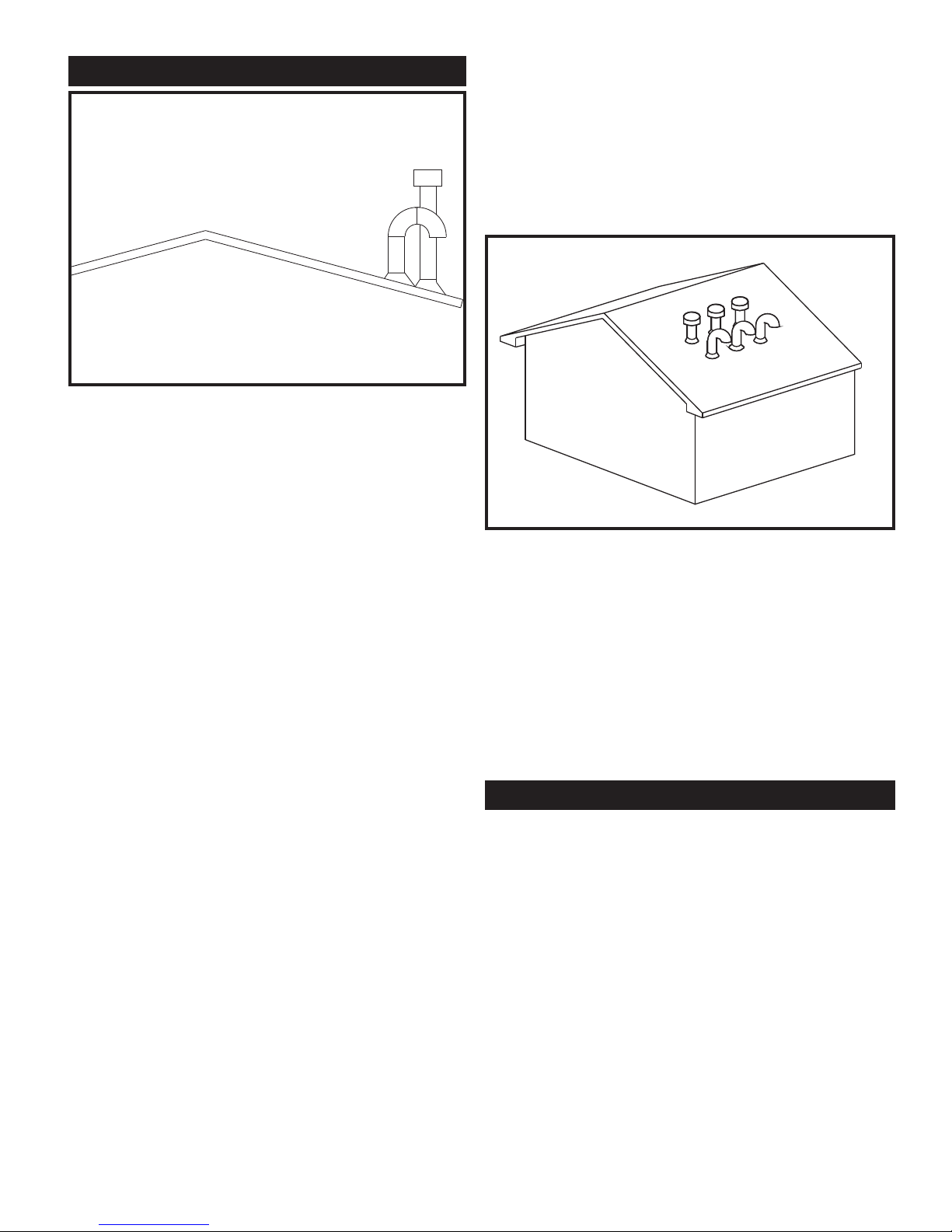
Multiple Vertical Direct Vent Installations
FIG. 22 Multiple Vertical Direct Vent Installations
The combustion air inlet caps for mul ti ple appliance installations
must maintain the minimum 3 foot (0.91 m) clearance below the
closest vertical flue outlet if within 10 feet (3.05 m). Multiple flue
outlet caps may be in stalled side by side and multiple air inlet caps
may be installed side by side but the air inlet must always be at
least 3 feet (0.91 m) below the closest flue outlet if the outlet is
within 10 feet (3.05 m). All clearance and installation requirements
in this sec tion and the applicable portions of the general Category
IV venting section must be maintained on multiple ap pli ance
installations.
For venting flue products horizontally to the outdoors, follow all
re quire ments in the installation instructions for sidewall venting.
Termination point for the flue products must follow the clearance
requirements in the Sidewall Vent Termination section of Category
IV Venting.
A Horizontal Direct Vent System is installed with a Category IV flue
and a separate combustion air pipe to the outdoors. The Direct Vent
system ter mi nates both the flue and air inlet in the same pressure
zone. The flue out let and combustion air intake must both terminate
on the same sidewall.
Follow all requirements in the General Category IV Venting
sections for proper installation and of venting flue prod ucts to the
outdoors with a sidewall termination. All other general
in stal la tion requirements must be followed.
HORIZONTAL DIRECT VENT
17
The Direct Vent system requires the installation of an additional
pipe to supply combustion air from outdoors directly to the
appliance. The air inlet pipe must use one of the spec i fied
materials.
The maximum installed length of the air inlet pipe from the
appliance to the air inlet cap is 100 equivalent feet (30.48 m) in
length. The maximum in stalled length of the flue pipe from the
appliance to the termination cap is 100 equivalent feet
(30.48 m) in length. Subtract 5 feet (1.52 m) of equivalent
length for each 90° elbow installed in either the flue pipe or the
air inlet pipe. Subtract 2 1/2 feet (0.7 m) of equivalent length for
each 45° elbow installed in either the flue or the air inlet pipe.
Termination point for the flue products must follow the clearance
requirements in the Sidewall Venting Termination sections of the
Category IV Venting.
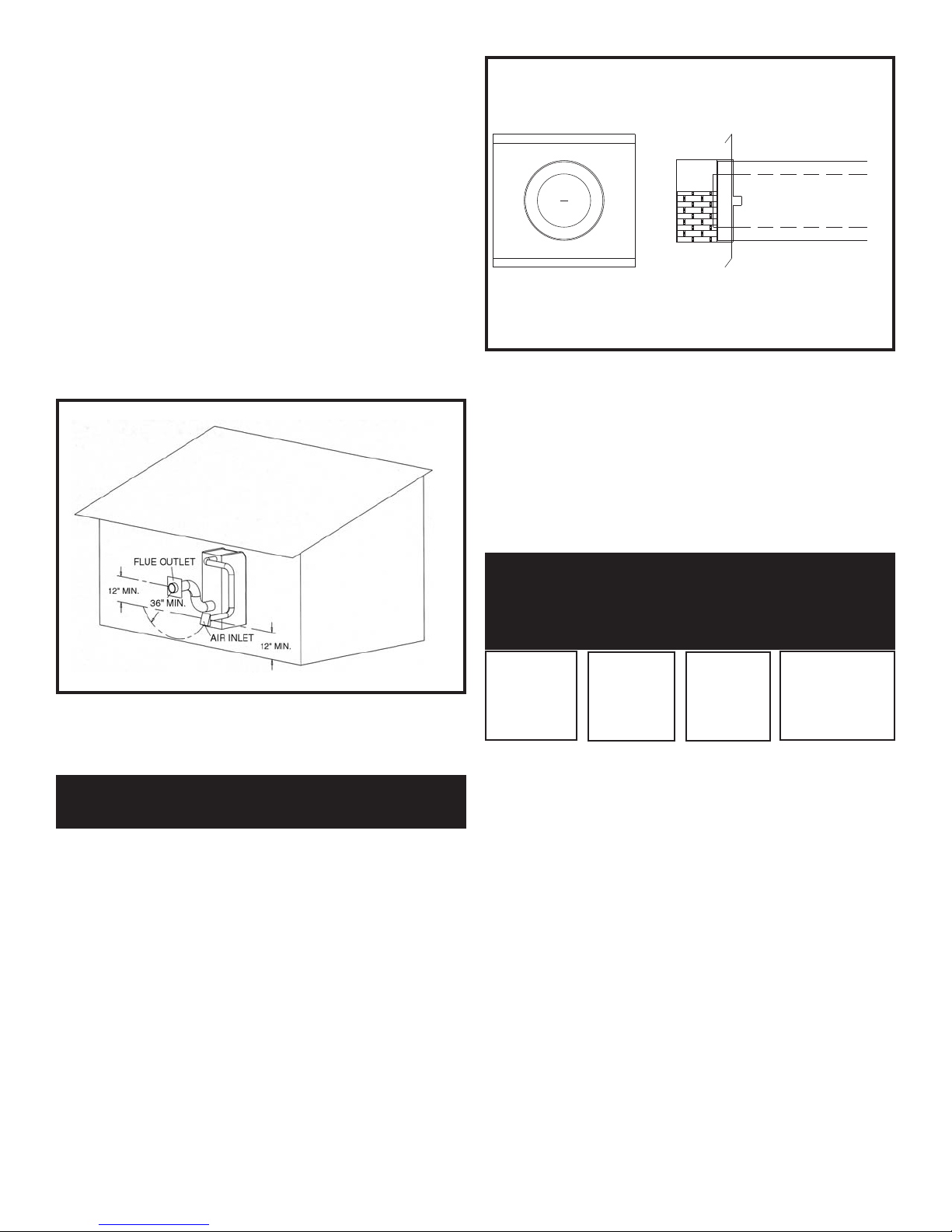
FIG. 23 Horizontal Direct Vent Installations with Sidewall
Combustion Air Inlet
SIDEWALL COMBUSTION
AIR INLET
Horizontal Direct Vent systems in stalled with sidewall terminations
for both combustion air and flue products must purchase the
termination caps from the appliance manufacturer. The sidewall
air inlet cap and sidewall vent cap for flue products are avail able as
a vent kit.
FIG. 24 Sidewall Vent Cap
The part numbers for the required sidewall air inlet cap kit are listed
by unit size. The manufacturer, in accordance with CSA
requirements, must furnish the sidewall air inlet cap. Each kit
includes the spe cial combustion air inlet cap for in stal la tion on an
exterior sidewall. The sidewall air inlet cap supplied in the kit is
sized to provide combustion air for a single appliance only.
TABLE - G
Flue Air Inlet Sidewall Air
Input Cap Cap Inlet & Flue
Btu/hr Size Size Cap Kit
1,500,000
___________
1,700,000
___________
2,000,000
6"
__________
7"
__________
8"
6"
__________
8"*
__________
8"
HDK3018
______________
HDK3019
______________
HDK3020
*Piping from the appliance to the air inlet cap may be either 7" or
8" connecting to an 8" sidewall cap provided in the kit.
Location of a Sidewall Air Inlet Cap
Incorrect installation and/or location of the air inlet cap can allow
the discharge of flue products to be drawn into the combustion
process on the heater. This can result in incomplete combustion and
potentially hazardous levels of carbon monoxide in the flue
products. This will cause operational problems with the heater and
possible spillage of flue products that can cause personal injury,
death or prop er ty damage.
The termination point of the sidewall air inlet must be installed a
minimum of 12 inches (0.30 m) above ground level and above
normal levels of snow ac cu mu la tion.
The point of termination for the sidewall combustion air inlet cap
MUST be located a minimum of 3 feet (0.92 m) horizontally and
12 inches (0.30 m) below the point of flue gas termination (vent
cap) if it is located within a 10 foot (3.05 m) radius of the flue
outlet.

18
The sidewall combustion air inlet cap MUST NOT be installed
above the sidewall flue outlet if it is located within a 10 foot
(3.05 m) radius of the flue outlet.
The sidewall combustion air inlet cap must not be installed closer
than 10 feet (3.05 m) from an inside corner of an
L-shaped structure.
The sidewall combustion air cap as sem bly used MUST
adequately protect the combustion air inlet from wind and
weather.
The sidewall combustion air inlet cap and flue gas outlet MUST
be located on the same sidewall surface and in the same pressure
zone.
Combustion air supplied from outdoors must be free of
contaminants (see Com bus tion and Ventilation Air). To pre vent
recirculation of flue products into the combustion air inlet, follow
all instructions in this section.
Multiple Horizontal Direct Vent Installations
FIG. 26 Multiple Horizontal Direct Vent Caps Installed on a
Sidewall
INTELLI-VENT SYSTEMS
The combustion air inlet caps for mul ti ple appliance installations
must maintain the same minimum clearance from the closest vent
cap installed within a 10 foot (3.05 m) radius of the point of flue gas
termination as specified in single appliance installations. Multiple
flue outlet caps may be installed side by side and multiple air inlet
caps may be installed side by side but the minimum clearance of
3 feet (0.91 m) horizontal radius and 12 inches (0.30 m) below the
closest flue outlet to the air inlet cap must be maintained. All
clearance and installation requirements in this sec tion and the
applicable portions of the general Category IV venting section
must be maintained on multiple ap pli ance installations.
An Intelli-Vent system is a Category IV flue installed with a
separate com bus tion air pipe to the outdoors. The
Intelli-Vent system terminates the flue and the combustion air inlet
pipe in different pressure zones. The Intelli-Vent system may
terminate the flue and combustion air in any one of three
configurations.
These are:
(1) The flue on the roof top and combustion air intake
on the sidewall;
(2) The flue on the sidewall and combustion air from
the rooftop;
(3) The flue on the sidewall and the combustion air on
a sidewall other than the sidewall where the flue
is located.
All appliances are shipped from the factory equipped for Category
IV venting system. The optional Intelli-Vent systems require the
installation of specific venting materials that are purchased locally.
Sidewall termination caps for flue products and combustion air
must be purchased from the manufacturer. The sidewall caps for
combustion air and flue products are available as vent kits. The
following is a detailed explanation of the installation re quire ments
for each venting system, components used and part numbers of
vent kits for each model.
Follow all requirements in the General Category IV Venting
sections for proper installation and of venting flue prod ucts to the
outdoors with either a rooftop or a sidewall termination. All other
general installation requirements must be followed.
The Intelli-Vent System requires the installation of an additional
pipe to supply combustion air from outdoors directly to the
appliance. The air inlet pipe must use one of the spec i fied
materials.
FIG. 25 Air Inlet Cap for Sidewall Termination
FLUE OUTLETS
3' HORIZONTALLY
AIR INLET CAP
1' BELOW FLUE
19
Combined Air Inlet Points
The air inlet pipes from multiple ap pli anc es installed with an
Intelli-Vent system can be combined to a single common connection
based on the cross sectional area of the common pipe as defined in the
Direct Vent basic in for ma tion section.
Maximum Length of an Intelli-Vent Sys tem
The maximum installed length of the air inlet pipe from the
appliance to the air inlet cap is 100 equivalent feet (30.5 m) in
length. The maximum in stalled length of the flue pipe from the
appliance to the termination cap is 100 equivalent feet (30.5 m)
in length. Subtract 5 feet (1.52 m) of equivalent length for each
90° elbow installed in either the flue pipe or the air inlet pipe.
Subtract 2 1/2 feet (0.7 m) of equivalent length for each 45° elbow
installed in either the flue pipe or the air inlet pipe.
VERTICAL INTELLI-VENT WITH
SIDEWALL COMBUSTION AIR
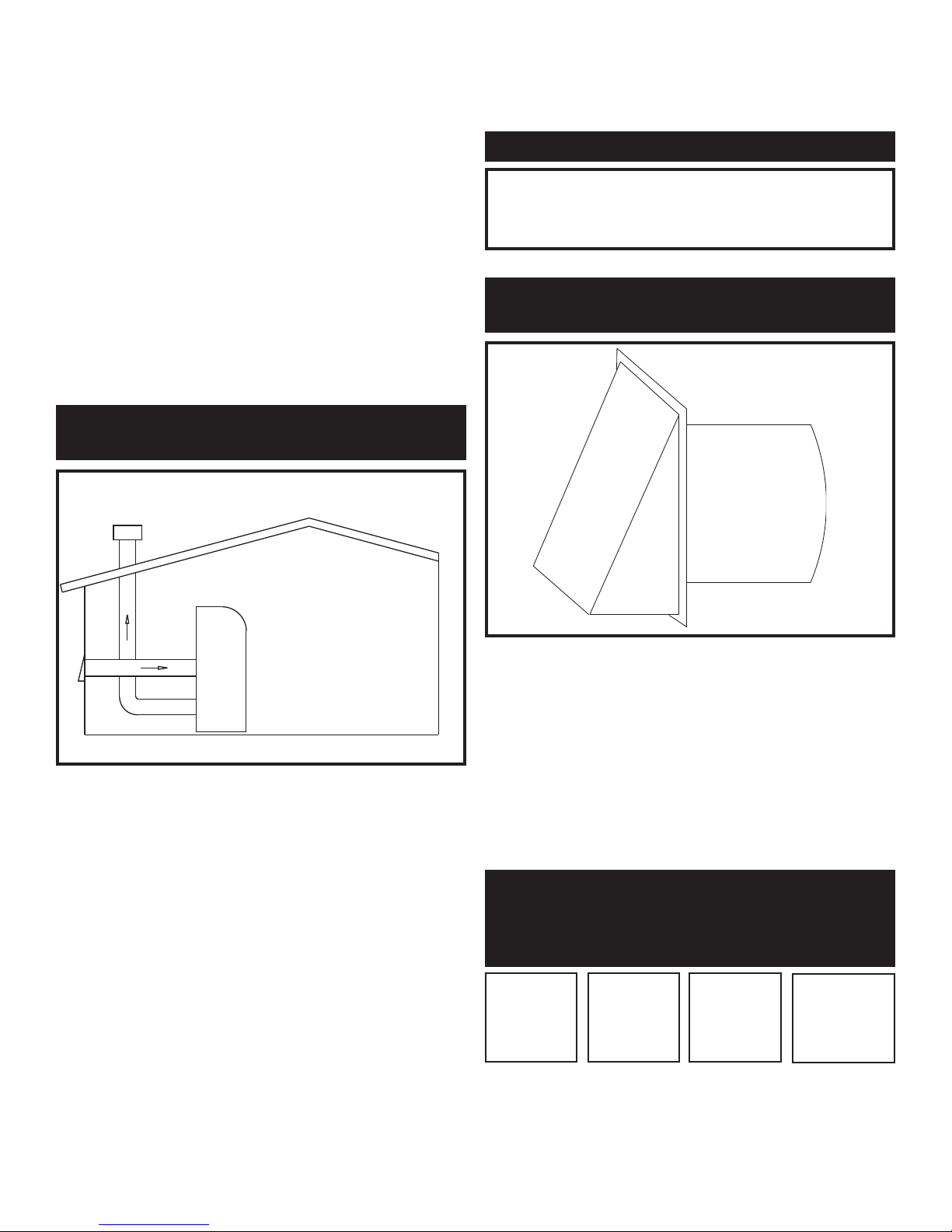
FIG. 27 Vertical Intelli-Vent Installation - Sidewall Combustion
Air Inlet
Intelli-Vent systems are installed with a Category IV flue and a
separate combustion air pipe to the outdoors. The Vertical
Intelli-Vent system ter mi nates the flue at the rooftop and air inlet
at the sidewall. The flue outlet and combustion air intake terminates
in different pressure zones.
Follow all requirements in the General Category IV Venting
sections for proper installation and venting of flue prod ucts
vertically to the outdoors. All other general installation
requirements must be followed.
The Intelli-Vent system requires the installation of an additional
pipe to supply combustion air from outdoors directly to the
appliance.
Termination point for the flue products must follow the clearance
requirements in the Vertical Vent Termination sec tion of the
Category IV Venting.
CAUTION
Appliances that are shut down or will not operate may
experience freezing due to convective airflow in the air inlet
pipe connected to the appliance.
SIDEWALL COMBUSTION
AIR INLET
FIG. 28 Air Inlet Cap for Sidewall Termination
The air inlet cap for the sidewall air inlet must be purchased from
the ap pli ance manufacturer.
The part numbers for the required sidewall air inlet cap kit are listed
by unit size. The appliance man u fac tur er, in accordance with CSA
requirements, must furnish the sidewall air inlet cap. Each kit
includes the special combustion air inlet cap for installation on an
exterior sidewall.
TABLE - H
Air Inlet Sidewall
Input Flue Pipe Air Inlet
Btu/hr Size Size Cap Kit
1,500,000
___________
1,700,000
___________
2,000,000
6"
___________
7"
___________
8"
6"
___________
7"*
___________
8"
SAK3000
___________
SAK3001
___________
SAK3002
*Piping from the appliance to the air inlet cap may be either 7" or
8" connecting to an 8" sidewall cap provided in the kit.
20
Location of a Sidewall Air Inlet Cap
Installation, location and clearance requirements for the sidewall
air inlet cap in an Intelli-Vent application are the same as the
installation, location and clearance requirements for the sidewall
air inlet cap in the Hor i zon tal Direct Vent section of the venting
instructions.
The sidewall combustion air inlet cap and the rooftop flue gas
outlet are located in different pressure zones in an Intelli-Vent
system.
Combustion air supplied from outdoors must be free of
contaminants (see Com bus tion and Ventilation Air). To pre vent
recirculation of flue products in to the combustion air inlet,
follow all instructions in this section.
Incorrect installation and/or location of the air inlet cap can allow
the discharge of flue products to be drawn into the combustion
process on the heater. This can result in incomplete combustion
and potentially hazardous levels of carbon monoxide in the flue
products. This will cause operational problems with the heater
and possible spillage of flue products that can cause personal
injury, death or prop er ty damage.
HORIZONTAL INTELLI-VENT WITH
VERTICAL COMBUSTION AIR
Intelli-Vent systems are installed with a Category IV flue and a
separate combustion air pipe to the outdoors. The Horizontal
Intelli-Vent system terminates the flue at the sidewall and air inlet
at the rooftop. The flue outlet and combustion air intake
terminate in different pressure zones.
FIG. 29 Horizontal Intelli-Vent Installation - Rooftop
Combustion Air Inlet
Follow all requirements in the General Category IV Venting
sections for proper installation and of venting flue prod ucts
horizontally to the outdoors. All other general installation
requirements must be followed.
The Intelli-Vent system requires the installation of an additional
pipe to supply combustion air from outdoors directly to the
appliance.
In cold climates, the use of type “B” double wall vent pipe or an
insulated single wall pipe is recommended to prevent moisture in
the cool incoming air from condensing and leaking from the inlet
pipe.
Termination point for the flue products must follow the clearance
requirements in the Horizontal Sidewall Vent Ter mi na tion section
of the Category IV Vent ing.
CAUTION
Appliances that are shut down or will not operate may
experience freezing due to convective airflow in the air inlet
pipe connected to the appliance.
The flue and air inlet duct sizes for a Horizontal
Intelli-Vent Installation with Rooftop Combustion Air Inlet are
listed by unit size. The sidewall vent cap must be purchased from
the ap pli ance manufacturer as a vent kit.
TABLE - I
Air Inlet Sidewall
Input Flue Pipe Vent
Btu/hr Size Size Cap Kit
1,500,000
___________
1,700,000
___________
2,000,000
6"
___________
7"
___________
8"
6"
___________
7"*
___________
8"
SVK3026
____________
SVK3027
____________
SVK3028
*Piping from the appliance to the air inlet cap may be either 7" or
8" connecting to an 8" sidewall cap provided in the kit.
12" MIN.
21
VERTICAL COMBUSTION
AIR INLET
FIG. 30 Air Inlet Cap for Rooftop Termination
The air inlet cap for the vertical roof top air inlet is assembled from
com po nents purchased locally. The air inlet cap consist of two 90°
elbows installed at the point of termination for the air inlet pipe.
The first 90° elbow is in stalled on the rooftop at the highest vertical
point of the air inlet pipe and turned horizontal, the second 90°
elbow is installed on the horizontal outlet of the first elbow and
turned down. A 90° elbow and a 90° street elbow may be used to
make this assembly. If a straight piece of pipe is used be tween the
two elbows, it should not ex ceed 6 inches (150 mm) in length. The
ter mi na tion elbow on the air inlet must be located a minimum of
12 inches (0.30 m) above the roof or above normal levels of snow
accumulation.
Location of a Rooftop Air Inlet Cap
Incorrect installation and/or location of the air inlet cap can allow
the discharge of flue products to be drawn into the combustion
process on the heater. This can result in incomplete combustion
and potentially hazardous levels of carbon monoxide in the flue
products. This will cause operational problems with the heater and
possible spillage of flue products that can cause personal injury,
death or prop er ty damage.
Installation, location and clearance requirements for the rooftop air
inlet cap in an Intelli-Vent application are the same as the
installation, location and clearance requirements for the rooftop air
inlet cap in the Vertical Direct Vent section of the venting
instructions.
The rooftop combustion air inlet cap and the sidewall flue gas outlet
are located in different pressure zones in an Intelli-Vent system.
Combustion air supplied from outdoors must be free of
contaminants (see Com bus tion and Ventilation Air). To pre vent
recirculation of flue products in to the combustion air inlet, follow
all instructions in this section and re lat ed Direct Vent sections.
In cold climates, the use of type “B” double wall vent pipe or an
insulated single wall pipe is recommended to help prevent moisture
in the cool incoming air from condensing and leaking from the inlet
pipe.
Termination point for the flue products must follow the clearance
requirements in the Horizontal Sidewall Vent
Ter mi na tion section of the Category IV Venting.
FIG. 31 Horizontal Intelli-Fin Installation with Sidewall
Combustion Air in a Different Pressure Zone
Intelli-Vent systems are installed with a Category IV flue and a
separate combustion air pipe to the outdoors. The Horizontal
Intelli-Vent system terminates the flue at the sidewall and the
combustion air on a sidewall other than the sidewall where the flue
is located. The sidewall flue outlet and sidewall combustion air
intake must terminate in different pressure zones.
Follow all requirements in the General Category IV Venting
sections for proper installation and of venting flue prod ucts
horizontally to the outdoors. All other general installation
requirements must be followed.
The Intelli-Vent System requires the installation of an additional
pipe to supply combustion air from outdoors directly to the
appliance.
HORIZONTAL INTELLI-VENT
WITH SIDEWALL COMBUSTION AIR
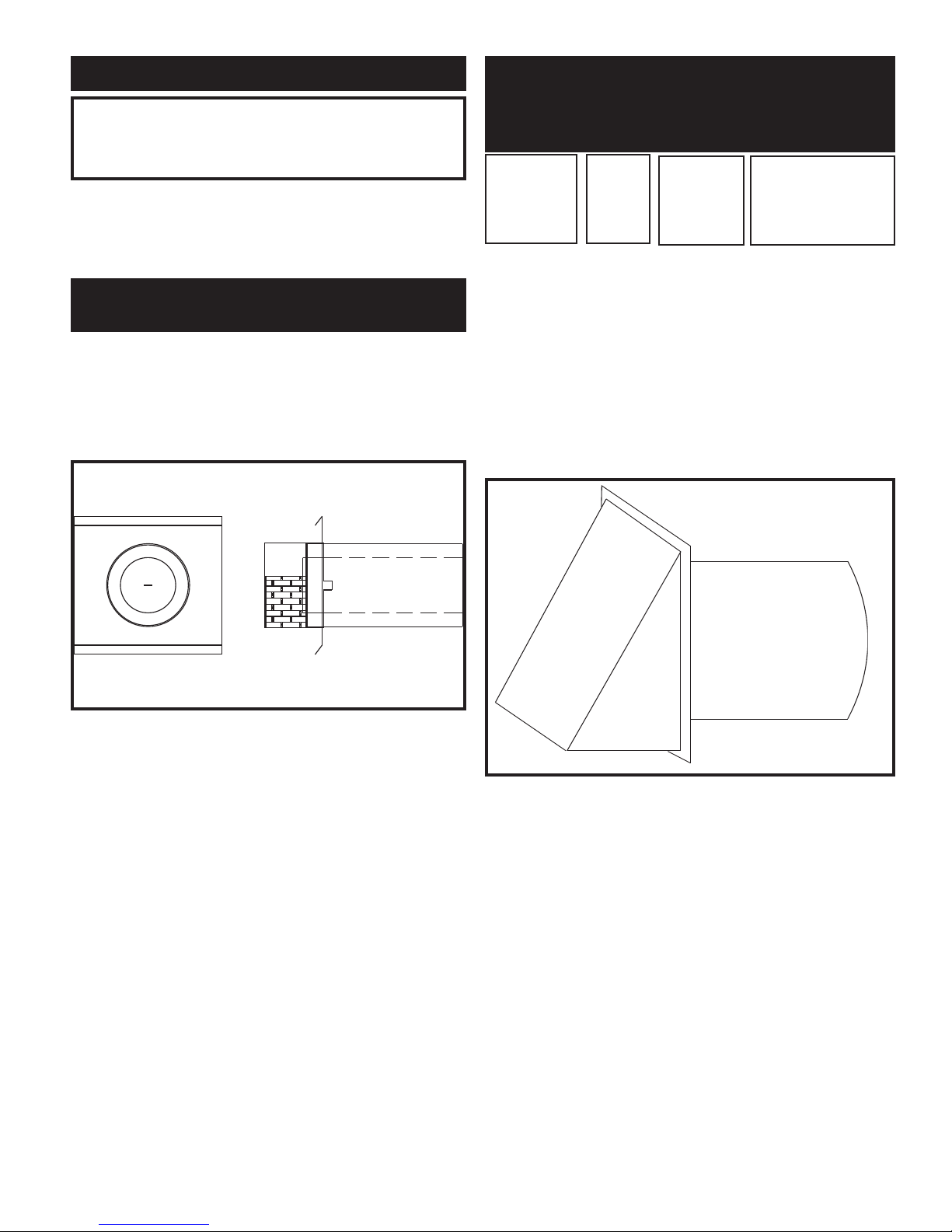
22
CAUTION
Appliances that are shut down or will not operate may
experience freezing due to convective airflow in the air
inlet pipe connected to the appliance.
The flue and air inlet duct sizes for a Horizontal
Intelli-Vent Installation with Sidewall Combustion Air Inlet are
listed by unit size.
SIDEWALL COMBUSTION
AIR INLET
Intelli-Vent systems installed with sidewall terminations for both
com bus tion air and flue products must pur chase the termination
caps from the appliance manufacturer. The sidewall air inlet cap
and sidewall vent cap for flue products are available as a vent
kit.
FIG. 32 Sidewall Vent Cap
The part numbers for the required sidewall air inlet and flue cap
kit are listed by unit size. The manufacturer, in accordance with
CSA re quire ments, must furnish both the sidewall air inlet and
flue cap. Each kit includes the both the special com bus tion air
inlet cap and the sidewall flue cap for installation on an ex te ri or
sidewall. The sidewall air inlet cap supplied in the kit is sized to
provide combustion air for a single appliance only.
TABLE - J
Flue Air Inlet Sidewall Air
Input Cap Cap Inlet & Flue
Btu/hr Size Size Cap Kit
1,500,000
___________
1,700,000
___________
2,000,000
6"
_______
7"
_______
8"
6"
_______
8"*
_______
8"
HDK3018
________________
HDK3019
________________
HDK3020
*Piping from the appliance to the air inlet cap may be either 7" or
8" connecting to an 8" sidewall cap provided in the kit.
Location of a Sidewall Air Inlet Cap
Installation, location and clearance requirements for the sidewall
air inlet cap in an Intelli-Vent application are the same as the
installation, location and clearance requirements for the sidewall
air inlet cap in the Hor i zon tal Direct Vent section of the venting
instructions.
FIG. 33 Air Inlet Cap for Sidewall Termination
The sidewall combustion air inlet cap and the rooftop flue gas outlet
are located in different pressure zones in an Intelli-Vent system.
Combustion air supplied from outdoors must be free of
contaminants (see Com bus tion and Ventilation Air). To pre vent
recirculation of flue products in to the combustion air inlet, follow
all instructions in this and related sec tions.
Incorrect installation and/or location of the air inlet cap can allow
the discharge of flue products to be drawn into the combustion
process on the heater. This can result in incomplete combustion
and potentially hazardous levels of carbon monoxide in the flue
products. This will cause operational problems with the heater and
possible spillage of flue products that can cause personal injury,
death or prop er ty damage.

23
GAS SUPPLY
Verify that the appliance is supplied with the type gas specified on
the rating plate. Consult factory for installations at altitude.
INLET PRESSURE: Measured at the inlet pressure tap on the
appliance gas man i fold. The pressure tap is located upstream
of the redundant gas valve and down stream of the field
installed gas cock.
TABLE - K
Inlet Gas Pressure
Natural L. P.
Gas Gas
Max. (Inches-Water Column)
______________________________
Min. (Inches-Water Column)
10.5" w.c.
________
4.0" w.c.
13.0" w.c.
_________
4.0" w.c.
Maximum inlet gas pressure must not exceed the value specified.
Minimum value listed is for the purposes of input adjustment.
MANIFOLD PRESSURE: Manifold pressure is a differential
pressure measurement made between the high and low pressure
taps at the gas orifice and the pres sure in the transition chamber
where the gas is supplied to the inlet of the combustion air blower.
All manifold gas pressures are noted at full firing rate. The controls
on this appliance may fire the burner from 25% up to 100% of rated
input, based on system demand. Manifold gas pressure will be
reduced as burner input is reduced. All ref er ence gas pressure
measurements must be made at 100% of rated burner input. The
gas manifold pressure is pre-set at the factory by the ratio gas valve.
Ad just ment of manifold pressure is not normally required for
proper operation. The adjustment point on the ratio gas valve is set
at the factory. DO NOT attempt to adjust the settings on the ratio
gas valve. Improper ad just ment of the ratio gas valve may cause
incomplete combustion or non-warrantable burner damage.
TABLE - L
Nominal Manifold Pressure
Settings at Full Fire
Natural L. P.
Input Btu/hr Gas Gas
1,500,000 - 2,000,000
3.5" w.c.
3.5" w.c.
GAS PRESSURE TEST
1. The appliance must be dis con nect ed from the gas
supply piping sys tem during any pressure testing
of that system at a test pressure in excess of 1/2
PSIG (3.5kPa).
2. The appliance must be isolated from the gas supply
piping system by closing a manual shutoff valve
during any pressure testing of the gas supply
piping system at test pressures equal to or less
than 1/2 PSIG (3.5kPa).
3. The appliance and its gas con nec tion must be
leak-tested before placing it in operation.
GAS CONNECTION
1. Safe operation of unit requires properly sized gas
supply piping. See gas line sizing data.
2. Gas pipe size may be larger than appliance
connection.
3. Installation of a union at the appliance gas line
connection is re quired for ease of service and
removal of the gas train.
4. Install a manual main gas shutoff valve, outside of
the appliance gas connection and before the gas
valve, when local codes require.
5. A trap (drip leg) MUST be pro vid ed in the inlet of
the gas con nec tion to the appliance.
6. The diaphragm gas valve has a bleed port that
requires venting to at mo sphere, outside the
building.
7. Optional gas controls may require routing of bleeds
and vents to the atmosphere, outside the building
when required by local codes.

24
TABLE - M
Recommended Gas Pipe Size
Single Appliance Installations
Distance from Meter
Btu/hr
1,500,000
2"
2 1/2"
2 1/2"
2 1/2"
2 1/2"
3"
3"
3"
3"
3"
3 1/2"
3 1/2"
3 1/2"
4"
1,700,000
2,000,000
0 - 50 ft.
51 - 100 ft. 101 - 200 ft.
201 - 300 ft. 301 - 500 ft.
For each elbow or tee, add equivalent straight pipe to total length from TABLE - O.
TABLE - N
Multiple Appliance Installations Gas Pipe Size Chart
lanimoN
,eziSepiPnorI
sehcnI
teeFthgiartSniepiPfohtgneL
010203040506070809001521051571002
4/3 96365250247155114182112131160159689747
1
796774483823292762642652012002971461941831
4/11 004,1479987776595345205274144014963333803782
2/11 051,2005,1012,1020,13290389677076666364653152
74144
2 001,4028,2062,2059,1027,1065,1044,1033,1052,1081,1001,1479178028
2/12 064,6064,4016,3001,3027,2064,2013,2001,2000,2009,10
07,1045,1004,1003,1
3 002,11009,7004,6004,5078,4014,4000,4008,3045,3003,3000,3027,2005,2043,2
4 005,32001,61001,31001,11000,0
1000,9003,8096,7083,7078,6051,6046,5031,5027,4
Maximum Capacity of Pipe in Thousands of Btu’s per hour for gas pressures of 14 Inches Water Column (0.5 PSIG) or less and a
pressure drop of 0.5 Inch Water Column (Based on NAT GAS, 1025 Btu’s per Cubic Foot of Gas and 0.60 Specific Gravity).
TABLE - O
Fittings to Equivalent Straight Pipe
Diameter Pipe Fitting (inches)
3/4" 1" 1 1/4" 1 1/2" 2" 3"
4"
5"
Equivalent Length of Straight Pipe (feet)
2' 2'
3' 4'
5' 10' 14' 20'

25
GAS PIPING
FIG. 34 Gas Line Connection to Unit with Sediment Trap
and Manual Main Gas Shut-off Valve
All gas connections must be made with pipe joint compound
resistant to the action of liquefied petroleum and nat u ral gas. All
piping must comply with local codes and ordinances. Tubing
installations must comply with approved standards and practices.
Install Piping to Control
1. The gas line should be a separate line direct from
the meter unless the existing gas line is of
sufficient capacity. Verify pipe size with your gas
supplier.
2. Use new, properly threaded black iron pipe free
from chips. If tubing is used, make sure the ends
are square, deburred and clean. All tubing bends
must be smooth and without deformation. Avoid
flexible gas connections. Internal diameter of
flexible gas lines may not provide appliance with
proper volume of gas.
3. Install a manual main gas shutoff valve at the units
gas inlet, outside of the appliance and before the
gas valve. Install a union at the ap pli ance gas
line connection for ease of service and removal of
the gas train.
4. Run pipe or tubing to the units gas inlet. If tubing
is used, obtain a tube to pipe coupling to connect
the tubing to the units gas inlet.
5. Install a sediment trap in the supply line to the
units gas inlet. (see Figure 34).
6. Remove seal over gas inlet to the appliance.
7. Apply a moderate amount of good quality pipe
compound (DO NOT use Teflon tape) to pipe only,
leaving two end threads bare.
8. Connect gas pipe to inlet of ap pli ance. Use wrench to
support gas man i fold on the appliance.
9. For LP gas, consult your LP gas supplier for expert
installation.
GAS MANIFOLD
PRESSURE ADJUSTMENT
The manifold gas pressure on the Intelli-Fin appliance is not field
adjustable. The ratio gas valve has been factory set with an internal
bias adjustment to ensure a 1:1 air/gas ratio on operation.
Tampering with this adjustment will void the warranty on the gas
valve assembly and the burn er. An Intelli-Fin supplied with a
properly sized gas line, properly sized meter and a minimum of 4
inch water column of gas supply pressure while firing at full rate
will ensure full burner in put. The manifold pressure supplied to the
burner is a differential pressure. This pressure is the result of the
difference in two gas pressure mea sure ments. A differential
manifold gas pressure measurement should not be made until you
have measured the gas supply pressure. Gas supply pressure must
be a minimum of 4 inch water column with all appliances on the
gas line firing at full rate before a manifold pressure measurement
is made. Use the following pro ce dure to check gas supply pressure
with a manometer connected to the inlet pressure tap on the gas line
connection at the rear of the appliance.
CHECKING GAS SUPPLY PRESSURE
FIG. 35 Gas Supply Pressure Measurement
GAS INLET
TRAP

26
1. Turn the main power switch to “OFF” position.
2. Shut off gas supply at the manual gas cock in the as
piping to the ap pli ance. If fuel supply is LP gas, shut
off gas supply at the tank.
3. Remove the 1/8" hex plug from the gas pressure
test port located on the inlet gas supply
connection at the rear of the appliance. Install a
fitting in the inlet pressure tapping suitable to
connect to a manometer or magnahelic gauge.
Range of scale should be 14 inch w.c. or greater to
check inlet pressure.
4. Turn on gas supply at the field installed manual
gas cock, turn on LP gas at tank if required.
5. Turn the power switch to “ON” po si tion and ensure
that the Run/Stop switch is in the “Run” position.
6. Adjust the temperature setpoint on the Command
Display to call for heat.
7. Observe the gas supply pressure as the burner
fires at 100% of rated in put. Percent of burner
input will be displayed on the Command Display.
8. Ensure inlet pressure is within specified range.
Minimum and Maximum gas supply pressures are
specified in Gas Supply section of this manual.
9. If gas pressure is out of range, contact the gas
utility, gas supplier, qualified installer or service
agency to determine necessary steps to provide
proper gas pressure to the control.
10. If gas supply pressure is within normal range,
proceed to remove gas manometer and replace
pressure tap fittings in the gas piping to the
appliance.
11. Turn the power switch to “OFF” po si tion.
12. Shut off gas supply at the manual gas cock in the
gas piping to the ap pli ance. If fuel supply is LP
gas, shut off gas supply at the tank.
13. Remove the manometer and related fittings from
gas pressure test port at the inlet gas supply
connection to the appliance. Replace 1/8" hex
plug in gas pressure test port and tighten.
14. Turn on gas supply at the manual valve, turn on
LP gas at tank if required.
15. Turn the power switch to “ON” position.
16. Adjust the temperature setpoint on the Command
Display to the desired water temperature so the
appliance will call for heat.
17. Check burner performance by cycling the system
while you observe burner response. The burner
should ignite promptly. Flame pattern should be
stable, see “Maintenance-Normal Flame Pattern.”
Turn system off and allow burner to cool, then
cycle burner again to ensure proper ignition and
flame characteristics.
IMPORTANT
Upon completion of any testing on the gas system, leak test
all gas connections with a soap solution while the main
burner is firing. Immediately repair any leak found in the
gas train or related components. DO NOT operate an
appliance with a leak in the gas train, valves or related gas
piping.
CHECKING MANIFOLD
GAS PRESSURE
There is a pressure test tree located in the top chamber of the
appliance. This pressure test point can be ac cess ed by swinging out
the front control panel. The pressure test tree is mounted on the
front edge of the com bus tion air blower. It consists of an angle
support and four test cocks. There is one cock for positive air and
one for negative air, one cock for positive gas and one for negative
gas. Manifold pressure measurement will utilize both the positive
and negative test points for gas.
1. Open the front controls panel and swing the
controls out. Locate the pressure test tree on the
front edge of the combustion air blower. The positive
and negative gas pressure terminals will be used to
check differential gas pressure from the gas manifold
and the air box. Each gas pressure connection
point will have a small manual cock to attach a hose.
2. Connect a hose from the positive gas and the negative
gas to each of the two sides of a manometer. This will
allow the two pressure points to be measured at
the same time. Open the two gas pressure test
point cocks.
3. Set the Command Display to a set point which will
fire the burner at 100% of rated input.
4. As the appliance comes on and fires, record the
inches of water column of displacement on both
sides of the manometer. The sum of these two
readings as they are effected by the two gas
pressures is the differential man i fold pressure.
5. The differential manifold gas pres sure should be
3.5 inches of water column (+ 0.1" w.c.) when the
burner is firing at 100% of rated input.
6. If the differential manifold pres sure is not 3.5
inches water column (+ 0.1" w.c.), recheck the gas

27
supply pressure and adjust to ensure a supply
pressure between 4.0 and 10.5 inches water
col umn natural gas (13.0" w.c. for propane) while
the appliance is firing at 100% of rated input.
7. This is a reference pressure only and is not field
adjustable. An ap pli ance supplied with a
minimum of 4 inch es water column of gas supply
pres sure will operate at the correct man i fold
pressure as the burner input var ies with
temperature demand.
8. Close the two gas pressure test cocks on the
pressure test tree and remove the hoses to the
manometer.
9. Close the front control panel.
IMPORTANT
Upon completion of any testing on the gas system, leak test
all gas connections with a soap solution while the main
burner is firing. Immediately repair any leak found in the
gas train or related components. DO NOT operate an
appliance with a leak in the gas train, valves or related gas
piping.
WATER CONNECTIONS
ET
FIG. 37 Water Connections
FIG. 36 Manifold Gas Pressure Measurement
AIR INLET
GAS
WATER OUTL
WATER INLET
FLUE OUTLET
– – – – = FIELD CONNECTED
3.5" W.C.= gas
MANIFOLD GAS PRESSURE
P

28
Inlet and Outlet Connections
For ease of service, install unions on inlet and outlet of the
appliance. The connection to the appliance marked “Inlet” on the
header should be used for return from the system. The
con nec tion on the header marked “Outlet” is to be connected to
the supply side of the system.
Minimum Pipe Size Requirements
Minimum water pipe connections to this appliance is 3 inch
(76.2 mm) pipe for single unit installations installed not more
than 70 equivalent feet (21.3 m) of pipe from the main system
loop or storage tank. The equivalent number of straight feet of
pipe for each valve and fitting in the connecting piping must be
considered to properly arrive at the total equivalent feet of
straight pipe in the field installed piping to the appliance. See
the pip ing requirements in the heating boiler or water heater
section of this manual. Consult factory if longer piping dis tances
are required for a specific application.
PRIMARY HEAT EXCHANGER
FIG. 38 Primary Heat Exchanger
This appliance uses two finned copper tube heat exchangers to
maximize the heat transfer process. The primary heat exchanger
is mounted in the inner jacket on the front side of the ap pli ance.
The primary heat exchanger is composed of two circular glass
lined cast iron headers with 24 vertical finned copper tubes. A
series of “V” shaped baffles are installed between the individual
tubes to control
the movement of the flue products over the finned copper surface
and increase heat transfer. Water enters the primary heat exchanger
and makes four passes over the area exposed to direct heat from
the burner. An internal cir cu lat ing pump ensures proper water flow
over the heat transfer surfaces during burn er operation. Water
temperatures in the primary heat exchanger are con trolled by the
operation of the au to mat ic bypass assembly. Operation of the
bypass maintains water temperatures above 130°F (54.4°C) in the
primary heat exchanger to prevent flue gas condensation on the
primary heat ex chang er surfaces.
SECONDARY HEAT EXCHANGER
FIG. 39 Secondary Heat Exchanger
A secondary heat exchanger is mounted in an inner jacket chamber
at the rear of the appliance. The secondary heat exchanger is
constructed from two glass lined cast iron headers and multiple hor i zon tal finned copper tubes. The secondary heat exchanger is
mounted in the dis charge of the flue products from the primary heat
exchanger. This allows additional heat to be absorbed from the flue
products exhausted from the com bus tion process. The return water
from the system passes through the secondary heat exchanger
before it enters the primary heat exchanger. This allows the coolest
return water temperatures to enter the secondary heat exchanger
before proceeding to the primary heat exchanger. When return
water tem per a tures are below approximately 130° F (54.4°C), the
flue products passing over the secondary heat exchanger may be
cooled below their dewpoint re sult ing in the formation of
condensate. The secondary heat exchanger has a special high

29
INTEGRAL BYPASS
HOT
WATER
OUTLET
SECONDARY
HEAT
EXCHANGER
COLD
WATER
INLET
PRIMARY
HEAT
EXCHANGER
PUMP
BYPASS VALVE
FIG. 40 Bypass Piping with Valve Actuator and Pump
temperature conformal coating to prevent any corrosive damage to
the copper tubes or cast iron head ers from the low pH condensate.
The protective coating is brown in color and covers both the
headers and finned tube surfaces. The secondary heat exchanger is
designed to maximize heat transfer efficiency by fully condensing
flue products. The inner jacket that houses the secondary heat
exchanger is designed to collect the flue gas con den sate and
discharge it from the jacket.
This appliance contains an integral bypass and circulating pump
that con nects the primary and secondary heat exchangers. A
floating-point automatic bypass valve regulates the flow of water
through the bypass between the two heat exchangers. The valve is
a butterfly type valve with an EPDM seat and a 24 VAC gear driven
motorized actuator. The appliance’s internal Excel-10 con trol ler
senses inlet water temperature to the primary heat exchanger and
pro vides a 24 VAC signal to open or close the valve as required.
Operation of the bypass is based on an assumed flue gas dewpoint
temperature of 130°F (54.4°C) as referenced in the ANSI standards.
The dewpoint of flue gasses becomes the minimum acceptable inlet
water temperature for the primary heat exchanger. Sustaining water
tem per a tures in the primary heat exchanger above the dewpoint
prevents formation of flue gas condensate on the primary heat
exchanger. The Excel 10 es tab lish es a dead band around the 130°F
(54.4°C) setting of +1.8°F (2°C). This means the actual
temperature can vary positive or negative approximately 2° around
the 130°F (54.4°C) minimum desired setting. The variable input
rate of the burner from 25% to 100% will also affect the po si tion of
the bypass valve as it adjusts to maintain primary heat exchanger
(Bypass) temperatures above the 130°F (54.4°C) setting. The inlet
temperature to the primary heat exchanger is displayed by the
command display and provides the Excel 10 the adjustment point
for the bypass valve. The inlet water tem per a ture to the primary
heat exchanger generally should not remain below the minimum
dewpoint temperature for more than approximately five minutes.
In this case, the inlet temperature to the primary heat exchanger is
rarely below 125°F (51.7°C). The actuator on the bypass valve will
take between a minimum time of 180 seconds up to a maximum
time of 300 seconds to move from a “full closed” position to a “full
open” position or vice versa. Operation of the bypass valve actuator
assures that water temperature in the primary heat exchanger is
maintained high enough to prevent condensate formation on the
primary heat exchanger.
BYPASS VALVE - Synchronization
As the main power is switched on and/or when the run/stop switch
is placed in the “RUN” position, the bypass valve will go through
a synchronization process to establish a reference point for op er a tion. After the initial synchronization on start-up, the bypass will
resynchronize in approximately 2 week intervals of normal
operation. This resynchronization will only occur in an off cycle
operation of an installed appliance. During the synchronization
process the Excel 10 controller will overdrive the valve actuator to
a full closed position. This establishes a reference point to assure
quicker re sponse to variation in inlet water temperature. The bypass
valve op er ates best when it can start operation from a full closed
position. A status point mode of Byp Synch will be in di cat ed in
the Command Display as the actuator on the bypass valve is
overdriven to the closed position for synchronization.

30
BYPASS PIPING ASSEMBLY
The primary and secondary heat ex chang ers are interconnected
with a bypass and pump mounted in 2 1/2 inch (63.5 mm)
diameter copper pipe. All access to the piping is from the rear of
the appliance. On initial start up, all air must be removed from
the bypass piping to ensure proper water flow through the
appliance. The bypass piping has an air bleed cock located on the
discharge side of the internal pump. This bleed cock should
allow any trapped air in the internal piping to be purged from the
piping before operation. The bypass piping also contains a flow
switch to sense operation of the circulating pump, bulb wells for
tem per a ture sensors and a relief valve(s).
INTEGRAL CIRCULATOR
The appliance has an integral cir cu lat ing pump mounted in the
bypass piping. The pump has a 3/4 H.P. motor wired for 120 volt,
single-phase operation as shipped. The on-off operation of the
circulating pump is controlled by the Excel 10 controller. The
pump will start and run continuously when the power switch is
in the “ON” position and the run/stop switch is in the “RUN”
posi tion. A flow switch installed in the bypass piping assembly
proves water flow.
Optional Intermittent Pump Operation
On-Off operation of the circulating pump is available as an
option. Cycling of the integral pump is controlled by the Excel
10 controller. The pump will start on a call for heat and a flow
switch installed in the bypass piping assembly proves operation.
After the burner cycles off and the call for heat is satisfied, the
pump will continue to operate for a timed period to remove any
residual heat from the combustion cham ber before the pump is
turned off. If the ambient temperature at the tem per a ture sensor
for the Excel 10 drops below 45° F (7.2° C) the circulator pump
will turn on to help prevent freezing of the heat exchanger.
BYPASS - Initial Set-up of Maximum Water Flow
On initial start-up of the Intelli-Fin the maximum water flow to
the two in ter nal heat exchangers must be manually set before the
automatic operation of the bypass begins.
FIG. 41 Bypass Valve and Actuator Assembly
Setting temperature rise on an Intelli-Fin with an automatic bypass
is ac com plished by disconnecting the power leads to the bypass
actuator at the multi-pin connector on the rear of the appliance,
declutching the actuator drive and manually closing the bypass
valve. Manual adjustment of the bypass must not be attempted
if the 24 VAC power leads are connected to the terminals on the
appliance, the ap pli ance is operating or if there is any torque on
the bypass valve by the ac tu a tor. Disconnect the 24 VAC power
leads to the valve actuator. The declutch button on the actuator must
be pushed down and held in the depressed position to disengage
the gear driven motor that operates the valve. The declutch button
must push in easily without forcing its movement. If the button
does not easily move when pushed, the valve is under torque.
Forcing the declutch button in will cause non-warrantable damage
to the actuator. Torque can be removed by disconnecting the power
leads to the valve actuator. With the declutch button fully
depressed, move the ac tu a tor handle till it is perpendicular to the
piping. This fully closes the by pass valve. The position of the
handle is the same as the position of the butterfly in the valve seat.
With the bypass fully closed, all inlet water flows through the
secondary heat ex chang er and then through the primary heat
exchanger. No water will flow through the bypass at this time. Turn
the appliance on and allow the burner to come on and fire at full rate
(100% of input as shown on the Command Dis play). Adjust the
field-installed ball valve in the outlet piping from the appliance to
achieve the proper tem per a ture rise for your specific model.
Adjustment to achieve this temperature rise ensures a maximum of
90 GPM to the bypass and pump when in operation.

31
TABLE - P
Temperature Rise At Full Rate Fire
Bypass Manually Fully Closed
Btu/hr Input Temperature Rise
1,500,000
_______________________
1,700,000
_______________________
2,000,000
31.5°F (17.5°C)
_______________________
35.7°F (19.8°C)
_______________________
42.0°F (23.3°C)
NOTE:
The Excel 10 controller makes all internal calculations in
°C and converts the displayed temperature to °F. This may
limit exact temperature adjustment. Setting of temperature
rise to the nearest °F is acceptable when setting maximum
flow.
Turn off power to the appliance. Reconnect the power leads to the
bypass actuator. Turn power on and place the run/stop switch in the
run position and allow the bypass valve to go through the
synchronization process before it begins normal operation.
WARNING
Moving the bypass handle while appliance is firing can
result in abnormally high water temperature that may cause
sudden relief valve discharge.
BYPASS OPERATION
1. Main burner ignition is achieved.
2. Integral bypass begins the ad just ment process to
control inlet water temperature to the primary heat
exchanger.
3. The Excel 10-controller senses inlet water
temperature to the primary heat exchanger.
4. Inlet water temperature into the primary heat
exchanger is displayed as “Bypass Temperature”
in one of the 21 points on the Command Display.
5. The floating-point bypass valve begins to adjust
position to maintain an inlet temperature to the
primary heat exchanger above the dew point of
flue products.
6. Minimum inlet water temperature to prevent
condensation of flue products is fixed at 130°F (54.4°C).
This con trol point is programmed into the soft ware in
the Excel 10 controller.
7. The Excel 10 provides 24 VAC to operate a high
torque motor in the actuator, which adjusts the
position of the floating-point bypass valve.
8. The actuator for the bypass valve adjusts in as
many as 500 micro-steps to achieve the desired
water tem per a ture at the inlet to the primary heat
exchanger.
9. With each micro-step of movement in the position
of the valve, the Excel 10 checks for a change in
water tem per a ture at the inlet to the primary heat
exchanger. As long as the inlet water temperature
is below 130°F (54.4°C) the bypass is moving
toward full open to increase the inlet water
temperature. When the inlet water temperature is
above 130°F (54.4°C) the bypass is mov ing toward
full closed to sustain the water temperature above
the dewpoint of the flue products.
10. Operation of the bypass valve main tains water
temperatures above the dew point of flue products
at the primary heat exchanger to ensure that
condensate formation occurs only on the
secondary heat exchanger.
The use of a Floating-Point Bypass Valve means that there is no
fixed open or closed position on the valve. If errant hands
manually move the bypass adjustment handle, it will take longer to
adjust to the proper setting but it will still function properly to main tain water temperatures.
CAUTION
Failure to disconnect power to the actuator before
declutching or manually moving the valve handle can cause
non-warrantable damage to the actuator.
MINIMUM WATER TEMPERATURES
A minimum return water temperature of 50°F (10°C) has been
established for each model based on the Btu/hr output at 100% of
rated burner input. The temperature set point for the Excel 10
controller sensing system temperature or stored water temperature
must not be set lower than the specified minimum for each model.
Maintaining inlet water temperatures to the appliance equal to or
higher than the specified minimum temperature setting ensures
proper op er a tion of the bypass and allows all con den sate formation
to occur on the sec ond ary heat exchanger. An appliance allowed
to sustain operation at water temperatures lower than the specified
minimum temperature may not provide enough heat from the
burner to maintain water temperatures in primary heat exchanger
above the 130°F (54.4°C) dew point of flue prod ucts. Operation of
the appliance at a temperature below the specified minimum set
point temperature will result in non-warrantable operational
problems from the con den sate formation on the primary heat
exchanger.

32
TABLE - Q
Minimum Inlet Water Temperatures
Input Minimum Return Minimum
Btu/hr Temperature Setpoint
1,500,000
___________
1,700,000
___________
2,000,000
105°F (40.6°C)
_______________
90°F (32.2°C)
_______________
70°F (23.9°C)
50°F (10°C)
____________________
50°F (10°C)
____________________
50°F (10°C)
CAUTION
An appliance allowed to operate at return temperatures
below the specified minimum settings may experience
problems with the operating controls, safety switches,
obstruction of the flue gas passages on the primary heat
exchanger, incomplete combustion and possible flue gas
spillage. Sustained operation at lower than specified
water temperatures may cause hazardous conditions that
may result in personal injury or non-warrantable damage
to the appliance.
A boiler installed above radiation level must be provided with a
low water cutoff device either as part of the unit or at the time of
installation.
WATER FLOW SWITCH
A water flow switch is factory in stalled in the internal bypass piping
on all heating boilers, hot water sup ply boilers and water heaters.
The flow switch is wired in series with the 24 VAC safety control
circuit. This wiring connection installs the flow switch in the 24
VAC safety circuit to prove water flow before main burner ignition.
A factory supplied flow switch installed in the discharge piping
from the top header requires a minimum flow of 26 GPM to make
the flow switch and start burner operation. A water flow switch
meets most code re quire ments for a low-water cut off device on
boilers requiring forced circulation for operation. A status point
alarm of LowH2OFlow will be indicated in the Command Display
on a low water con di tion as sensed by the flow switch.
LOW WATER CUTOFF
(If Equipped)
If this boiler is installed above ra di a tion level, a low water
cut-off device must be installed at the time of boiler installation.
Electronic or float type low water cut-offs are avail able as a factory
supplied option on all models. Low water cut-offs should be
inspected every six months, including flushing of float types. A
status point alarm of LowH2OFlow will be indicated in the
Command Display on a low water condition as sensed by a low
water cutoff.
GAS TRAIN AND CONTROLS
FIG. 42 Gas Train Assembly
DIAPHRAGM
VALVE
ORIFICE
RATIO VALVE

33
RELIEF VALVE
This unit is supplied with a relief valve(s) sized in accordance with
ASME Boiler and Pressure Vessel Code, Sec tion IV (“Heating
Boilers”). The re lief valve(s) is installed in the
ver ti cal position and mounted in the hot water outlet. No valve is
to be placed between the relief valve, and the unit. To prevent water
damage, the discharge from the relief valve shall be piped to a
suitable floor drain for disposal when relief occurs. No reducing
cou plings or other restrictions shall be installed in the discharge
line. The discharge line shall allow complete drainage of the valve
and line. Relief valves should be manually operated at least once
a year.
CAUTION
Avoid contact with hot discharge water.
NOTE:
The gas train and controls assembly provided on this unit
have been tested under the applicable American National
Standard to meet minimum safety and performance criteria
such as safe lighting, combustion and safety shutdown
operation.
RATIO GAS VALVE
FIG. 43 Ratio Gas Valve
The main gas valve supplying gas to the burner on this appliance
utilizes a pressure regulating electro hydraulic actuator providing a
slow opening, fast closing safety shut off and air/gas ratio control
for the gas combustion process. This gas valve controls the
pressure difference across the re stric tion in the gas supply line as a
func tion of the pressure difference across the combustion air supply
to the burn er. The actuator maintains a con stant air to gas ratio as
the volume of air changes based on the operation of the combustion
air blower. The valve is a 1:1 differential pressure air/gas ratio
controller. The valve adjusts the same pressure difference on the
gas side as it senses on the air side. The valve performs the
functions of safety shutoff, constant pressure regulation and air/gas
ratio control. Slow open ing and safety shutoff is accomplished by
operation of an electro hydraulic cylinder. Full closing of the valve
seat occurs in less than 0.8 seconds when the valve is de-energized.
A visual stroke position indicator is provided on the valve assembly
to in di cate the position of the valve seat. Operation of the gas valve
in com bi na tion with the combustion air blower allows the burner
input rate to vary from 25% to 100% based on temperature demand.
There is no need for an ad di tion al upstream constant gas pressure
regulator internally to the appliance as long as the gas supply is
maintained within the specified minimum and max i mum pressures.
The manifold pressure is preset at the factory and adjustment is not
usually required if gas supply pressure is maintained within the
specified range. If the manifold pressure is to be mea sured, follow
the “Gas Manifold Pres sure Measurement Procedure” for proper
measurement.
There are no serviceable parts on the ratio gas valve actuator.
DIAPHRAGM GAS VALVE
FIG. 44 Diaphragm Gas Valve
A diaphragm type gas valve is also provided in the gas train. As the
second valve seat in the gas train, it supplies a redundant safety
shutoff valve seat in the gas supply to the burner to ensure safe
operation in the remote event of a gas valve failure. The diaphragm
gas valve is energized with 24 VAC power at the same time the
ratio gas valve is powered in the op er a tion al sequence to ignite the
burn er.

34
Venting of Gas Valves and Pressure Switches
The diaphragm type gas valve and op tion al gas pressure switches
are pro vid ed with threaded termination points to be vented to the
atmosphere, outside the building. The gas pressure reg u la tion
function is provided by the ratio gas valve which does not require
in stal la tion of a vent line. The di a phragm gas valve and optional
gas pres sure switches are installed in the upper chamber of the
appliance. Threaded vent line connections from components
requiring an external vent line are provided on the component.
These vent line connection points may be accessed by removing
the top jacket panels. Local codes may require the routing of
these bleeds and vents to the atmosphere, outside the building.
Proper routing of vent lines to the atmosphere from the factory
supplied termination points is the re spon si bil i ty of the installing
contractor.
ELECTRICAL CONNECTIONS
FIG. 45 Electric Power Connections - Controls and Pumps
A 120 VAC, 15 Amp, 1 ph, 60 Hz circuit is required for operation
of the integral circulating pump and a 120 VAC, 15 Amp, 1 ph,
60 Hz circuit for the ap pli ance controls are recommended. If a
single electrical service is provided to operate both the controls
and pump, a 120 VAC, 30 Amp, 1 ph, 60 Hz circuit is
recommended. The combustion air blower motor operates on
230 VAC, 3 ph, 60 Hz. This three phase voltage is generated by
the variable frequency drive (VFD) and supplied directly to the
blower motor. NOTE: No 230 VAC electrical service is
required for operation of the combustion air blower.
The appliance, when installed, must be electrically grounded in
accordance with the requirements of the authority having
jurisdiction or in the absence of such requirements, with the latest
edition of the National Electrical Code ANSI/NFPA No. 70. When
the unit is installed in Canada, it must conform to the CAE C22.1,
Canadian Electrical Code, Part 1 and/or local Electrical Codes.
1. All wiring between the appliance and field installed
devices shall be made with type T wire
[63°F (35°C) rise].
2. Line voltage wire exterior to the appliance must be
enclosed in approved conduit or approved
metal clad cable.
3. The pump must run continuously when appliance
is being fired. The Excel 10 temperature controller
will energize the integral circulating pump for
continuous operation when the main power switch
is in the “ON” position and the run stop switch is
in the “RUN” position. If the internal water
temperature drops below 45°F (7.2°C) the pump
will automatically cycle on to help prevent freezing
(see Freeze Protection).
.
4. To avoid serious damage, DO NOT energize the
appliance until the system is full of water. Ensure
that all air is removed from the bypass piping
before beginning initial operation. Se ri ous damage
may result if the ap pli ance is operated without
proper flow.
5. Provide the appliance with proper overload
protection.
TABLE - R
AMP DRAW DATA
1,000,000 through 2,000,000 Btu/hr Models
APPROXIMATE TOTAL
Blower & Pump Amps
Btu/hr Controls FLA @ 120 AC
1,500,000
__________
1,700,000
__________
2,000,000
15.5
____________
16
____________
16
8.8
__________
8.8
__________
8.8
6.7
____________
7.2
____________
7.2
JACKET ASSEMBLY
Inner Jacket - The inner jacket as sem bly is constructed from a
special cor ro sion resistant stainless steel. This includes both the
front primary heat exchanger chamber and the rear sec ond ary heat
exchanger chamber. All screws and fasteners used for assembly of
ELECTRICAL
JUNCTION BOX
CONTROL
PUMP

35
the inner jacket and secondary heat exchanger chamber are also
stainless steel. The stainless steel screws are identified by a sealing
washer mounted on each screw. DO NOT mix stainless steel and
standard plated fasteners when disassembling and
reassembling the inner jacket sheet metal components.
Standard plated fasteners may be dam aged by the flue product
condensate when used on the inner jacket as sem blies.
Outer Jacket - The outer jacket as sem bly is constructed from steel,
gal va nized on both sides. The galvanized surface is specially
prepared and phos phate coated to allow application of a multiple
coat enamel paint process. This coating process ensures a long life
from the jacket assembly.
ACCESS TO COMPONENTS AND CONTROLS
FIG. 47 Front Control Panel Locations
FIG. 46 Component and Auxiliary Controls Connections with Junction Box

36
FIG. 48 Transformer and Relay Locations
VARIABLE FREQUENCY DRIVE
FIG. 49 Internal Control Panel Location
FIG. 50 Variable Frequency Drive
A transformer and relay mounting panel is located above the front
control panel, underneath the curved exterior front jacket panel.
This panel contains a 100 VA transformer to drop 120 VAC to
24 VAC for internal control operation, an optional electronic low
water cut-off, a high limit alarm re lay, an alarm relay, an ignition
relay, gas valve relay, pump relay, louver relay and VFD power
relay.
This appliance uses a variable frequency drive (VFD) to control
operation of the combustion air blower motor. The variable
frequency drive is supplied with 120 VAC power. The blower motor
operates on 230 VAC 3 phase power. This three phase voltage is
generated by the variable frequency drive and supplied directly to
the blower motor. The variable frequency drive receives a signal
from the Excel 10 controller based on water temperature to vary
the frequency of the voltage supplied to the blower motor from
15 Hz up to 60 Hz. This varies the output of the combustion air

37
blower from 25% up to 100% of capacity corresponding to the
same variation in burner input. The output from the Excel 10 to
the variable frequency drive ensures that combustion air and gas
are always supplied in the proper ratio for clean combustion. The
vari able frequency drive is driven to 100% during the pre-purge
portion of the start-up sequence. The variable fre quen cy drive is
then provided a signal to operate at 50% for initial burner ignition.
After main burner ignition is established, the Excel 10 will use the
variable frequency drive to vary the blower speed based on desired
water temperature set point, the variation in actual water
temperature from the de sired set point and the various op er at ing
characteristics programmed into the control’s software.
When removing the variable frequency drive from the appliance,
disconnect the power wires to the combustion air blower at the
terminals on the variable frequency drive. DO NOT disconnect the
power wires at the blower motor. Note the marking of the wires for
proper reinstallation of the three phase power wires to the VFD.
Both the wires and the VFD terminals are marked for proper
location of wire terminals. Incorrect installation of the wires may
reverse rotation of the blower motor resulting in major operational
problems.
CAUTION
The voltage output from the variable frequency drive to the
combustion air blower is 230 volt 3 phase. Avoid contact
with high voltage wiring.
LOW AIR PRESSURE SWITCH
FIG. 51 Low Air Pressure Switch
FIG. 52 Excel 10 Control Module
EXCEL 10
A differential air pressure switch is used to prove operation of the
com bus tion air blower. The pressure switch sensing points are
installed across the point of pressure drop as the air moves into the
inlet of the burner. This switch measures the same pressure drop
points similar to those used by the ratio gas valve to adjust manifold
gas pressure. Cor rect differential pressure across the sensing points
of the pressure switch proves operation of the combustion air
blower to the Excel 10 control. The Command Display will exhibit
a Status Alarm of LowAirPress and the appliance will shut down
operation when the differential pressure switch detects a sustained
low air condition.
HIGH GAS PRESSURE SWITCH
LOW GAS PRESSURE SWITCH
(Optional)
High and/or low gas pressure switches are available as an option on
this appliance. The high gas pressure switch is used to monitor the
maximum gas supply pressure supplied to the gas train. If gas
pressure exceeds the maximum setting of the pressure switch, the
appliance will shut down and a gas pressure fault will be indicated
in the Command Display. The low gas pressure switch is to
monitor the minimum gas supply pressure supplied to the gas train.
If gas pressure falls below the minimum setting of the pres sure
switch, the appliance will shut down and a gas pressure fault will
be indicated on the Command Display. GasPressFail will be shown
on the Display for either a high or low gas pressure problem.
PRESSURE SWITCH
BLOWER
~
TRANSITION
BURNER
~
~
~
~
~
~
~

38
Excel 10 Boiler Interface Controller - The boiler interface
control ler for this appliance is based on the Excel 10 controller
platform with unique software customized for op er a tion of the
Lochinvar Intelli-Fin. The Excel 10 is also compatible with
LonWorks
®
building management systems. All of the appliances’
internal safety, operating and ignition controls in ter face with the
Excel 10 controller. Local communication, programming and a
digital display of the appliance func tions and operating
conditions are accessible through a Command Display. The
Command Display is mounted on the front control panel of the
appliance as shipped from the manufacturer. If mul ti ple Intelli-Fin
appliances are to be installed in a single application, see
“Multiple Appliance Installations” for information on interfacing,
sequencing and display of multiple Intelli-Fin appliances.
NOTE:
A single Command Display is shipped for each job site
installation with up to 16 Intelli-Fin appliances. A
single Command Display is used to display and access
the operating conditions of up to 16 Intelli-Fin
appliances.
The Excel 10 Boiler Interface Control serves as the operating
temperature control to regulate the amount of heat added to the
water system for both heating boilers and potable water heat ers.
Custom software programmed into the Excel 10 will determine
the proper operating profile for your specific application. Ensure
that an Intelli-Fin is properly applied. A unit or dered as a heating
boiler must be ap plied as a heating boiler and a unit ordered as a
potable water heater must be applied as a water heater. The Excel
10 Boiler Interface Control provides on/off control of the gas
supply to the burner, operation of a VFD to control a variable
speed combustion air blower, interface with the ignition control
system, on/off control of the integral circulating pump, operation
of a float ing point bypass valve, control of water temperature set
points, and mon i tor ing of all safety functions. The operation and
status of these and all related functions are displayed on the
Command Display.
The Excel 10 has a single LED located in the middle of the control
module. In normal operation of a boiler equipped with an optional
outdoor reset function, this LED will blink at the rate of one blink
per second. Active alarms will blink this service LED at a faster
than normal rate of two blinks per second to indicate an alarm. The
alarms which are displayed in this manner are: Network
communications failure, sensor failure, hard lockout, water flow
failure, low air, blocked drain, low/high gas pressure, flame failure,
soft lockout, heat mode fail ure, high temperature alarm, and boiler
not operational. A boiler that is not equipped with the outdoor reset
func tion or a water heater will always blink the LED at the faster
rate of approximately two blinks per second. This LED is not to
be used as a di ag nos tic indicator.
The Excel 10 controller is mounted on the backside of the front
control panel that mounts the Command Display and the Ignition
Control Module. This panel is hinged on the right side so it can be
exposed for viewing and service. All connections from the
appliance safety and operating controls to the Excel 10 are
accomplished with multiple wiring harnesses. Each wiring harness
is connected to unique multiple pin terminations to ensure proper
con nec tion of all components. The multiple termination points are
located on two printed circuit boards mounted on ei ther side of the
Excel 10 controller. Use caution when connecting or dis con necting
wires at the plug in terminals to prevent damage to the printed
circuit boards.
There is a bar code label on the back of the Intelli-Fin near the
terminal connections. This is the Neuron I.D. label which identifies
the exact nu mer i cal sequence applied to the Excel 10 control
installed in the boiler/water heater. This information is required for
the local/remote communication network. The numerical sequence
FIG. 53 Excel 10 Control Module with Circuit Boards and Wire Terminal Connections

39
is unique to each Excel 10 and must be placed into the network of
an energy management system so that the Excel 10 can be
recognized by the system. NOTE: If the Excel 10 is ever
replaced, a tear-off label on the new Excel 10 must be placed
over this label on the back of the unit for easy ref er ence.
The Excel 10 may have values for the control points specified at the
time the control is configured at the fac to ry. If exact control
settings are not specified at the time an appliance is ordered, the
Excel 10 controller will be pre-programmed with the fol low ing
default values as shipped from the factory. Special arrangements
should be made with the factory during the ordering process to have
job site spe cif ic values programmed into the con trol. These values
are different for boiler and water heater applications.
TABLE - S
Default Values
Pre-programmed in the Excel 10
Point
_______________
Setpoint Temp
_______________
O.A. Lockout
_______________
O.A. Max
_______________
O.A. Min
_______________
Max Setpoint
_______________
Min. Setpoint
_______________
Operating Sensor
_______________
Heater I.D.
Water Heater
_______________
120.0°F
_______________
N/A
_______________
N/A
_______________
N/A
_______________
190.0°F
_______________
50.0°F
_______________
Return/Inlet
_______________
Water Heater
Boiler
_______________
130.0°F
_______________
70.0°F
_______________
60.0°F
_______________
10.0°F
_______________
220.0°F
_______________
100.0°F
_______________
Return/Inlet
_______________
Boiler
MANUAL OVERRIDE CONTROL
This unit is trimmed with an auxiliary thermostat to provide a
manual override in the event of a failure of the Sequencer Control
or the Excel 10. When the manual override is activated, it will
provide temporary control until a replacement Sequencer or Excel
10 can be installed.
The manual override fires the appliance at 100% Btu/hr input rate
during the entire cycle. Modulating burner control is not available
with the manual override. In addition, the pump will run
continuously. Intermittent pump operation is not available with the
manual override.
Modulation of the bypass valve may not be available with the
manual override. If the primary control failure is in a remote
Sequencer, the bypass valve should modulate. If the Excel 10
inside the appliance has failed, the bypass valve may not modulate.
The manual override is located on the back of the appliance below
the bypass piping loop. To the left of the thermostat is a toggle
switch to alternate the control of the appliance from the primary
control to the manual override thermostat.
Some models may have a reduced firing rate when manual override
is activated.
To Activate the Manual Override:
1. In the event of a failure of the primary control, move the
“Stop/Run” switch on the front of the control panel to “Stop”.
2.
Move the toggle switch, located on the back of the unit to
“Manual Override”.
3. If the bypass valve does not modulate under the control of the
manual override thermostat, it will be necessary to manually to
set the bypass valve to deliver a minimum 140°F water
temperature to the primary heat exchanger following the
procedure below:
a. Disconnect the bypass valve’s 3-pin wire harness from its
connection in the junction box on the upper left of the rear
of the appliance.
b. If the Excel 10 readout function is still active, check the
“Return/In Temp” for a return water temperature the unit
might see in regular operation.
c. Press the “Down” or “Up” arrow key to find the “Bypass
Temp” readout.
d. Fire the unit with the manual override control. As the unit
reaches a steady state operation, depress the clutch
mechanism and turn the handle slowly counterclockwise to
open the bypass valve to a point at which the “Bypass
Temp” is 140°F.
e. Release the clutch and leave the valve in this position until
the primary control can be replaced. Do not
reconnect the
3-pin bypass wire harness.
To Return to the Primary Control:
1. After the replacement primary control is installed, reconnect
the 3-pin bypass wire harness.
2. Move the toggle switch to “Primary Control”.
3. Turn the manual override thermostat to the lowest setting.
4. Move the “Stop/Run” switch to “Run”.
If you have any questions or comments, please call the Lochinvar
Technical Product Service Line at 1-800-722-2101.
TEMPERATURE ADJUSTMENT
COMMAND DISPLAY
FIG. 54 Command Display Panel

40
The Command Display provides a com mu ni ca tion interface with
the Excel 10 via a series of display screens. The front view of the
display screen shows the digital display with a cluster of arrow
keys on the lower left side. These directional arrow keys move
the cursor in the direction of the arrow.
On the lower right side is a back key which moves the display to
the previous screen and a select key which high lights a field in
the display.
There are also four softkeys along the right side of the display. A
notation on the specific screen defines the function of each of
these keys. The softkeys may be defined as configure, change,
save, cancel, + to increase a value or - to decrease a value on the
screen.
PASSWORD FUNCTION
On initial operation of the Intelli-Fin the owner may enter three
levels of password with the Command Display to limit access to
the changeable op er at ing parameters in the Excel 10. Each
password is composed of a four digit number. As shipped from
the factory all passwords are zeros. The first level of password
allows access to the six changeable points accessible from the
Command Display. The second level of password allows access
to the configura tion settings of the Command Display. The third
level of password allows the password to be changed.
FIG. 55 Command Display Password Screen
The configure button also allows the user to access the password
function to enter a password in the Excel 10 from the Command
Display. Use of a password will limit the access to the
changeable points. When located at the password screen, move
the cursor to the first blank space (by using the left or right
buttons on the left side of the Command Display). Use the “+”
or “-” buttons on the right side of the Command Dis play to either
increase (+) or decrease (-) the number to the desired number.
Then use the left or right buttons to move the cursor to the next
space and repeat this procedure. Once the pass word has been
entered, push the “SAVE” button. Once a password number
sequence has been entered into the Command Display, they must
be correctly reentered to change any of the six adjustable points.
If an incorrect password sequence is entered, the pass word screen
will stay in place.
NOTE:
Once a password is correctly entered, it will not have to be
reentered unless five minutes of inactivity on the Command
Display has elapsed.
CONFIGURING THE
COMMAND DISPLAY
When the “CONFIGURE” button on the right side of the Command
Display is pressed, a password screen will appear. The user must
enter the appropriate password and press “SAVE” to access the
changeable screen. Pressing this but ton provides access to a
“setup” screen that allows the user to adjust such items as:
TABLE - T
DISPLAY DEFAULT VALUES
____________________
Contrast
____________________
Backlight Mode
____________________
Beep on New Alarm
____________________
Beep Rate
____________________
Time Format
____________________
Date Format
____________________
Engineering Units
Option
_____________
0 - 100%
_____________
OFF/ON
_____________
ON
_____________
0 - 60s
_____________
24
_____________
DD/MM/YY
_____________
S.I.
Default
_____________
50%
_____________
AUTO
_____________
OFF
_____________
4.0s
_____________
12
_____________
MM/DD/YY
_____________
English
ACCESSING THE SIX
CHANGEABLE POINTS FROM
THE COMMAND DISPLAY
When the “CHANGE” button on the right side of the control is
pressed, a pass word screen will appear. The user must enter the
appropriate password and press “SAVE” to access the changeable
screen. The desired point to change must be highlighted by moving
the cur sor and then use the “+” or “-” buttons on the right side to
change the value to the desired value. Once the desired value is
reached, press the “SAVE” button and the new value will be saved
and the Command Display will return to the first screen of the 21
points for that boiler/water heater. The password must be entered
each time a user wants to change the settings of any of the six
changeable points. However, if you go to the screen again within
5 minutes of the last time, it will not require the password again. If
the screen is left in the changeable point screen for more than 5
minutes with no activity, it will automatically return to the first
screen of the 21 points for the boiler/water heater. Re-entry into this
changeable point screen will then require password access again.

41
NOTE:
Allow 10 seconds for data shown in the display screens to
update when viewing or making adjustments to any of the
six adjustable points.
POINTS FROM INFORMATION
VISIBLE FROM THE SCREEN OF
THE COMMAND DISPLAY
1. Calculated Set Point — The water temperature as
adjusted by an optional outdoor reset function
used on a heat ing boiler only. If no outdoor reset
function is used, this displays the same
temperature as the set point. Outdoor Air Reset
function not available on a water heater application.
2. Set Point Temp — The desired water temperature
as adjusted by the owner/operator. This becomes
the lowest boiler operating temperature when an
optional outdoor reset function is used (Changeable Point
from the Com mand Display).
3. Return/Inlet Temp — The tem per a ture of the water
entering the boiler or water heater, a basic thermometer
function to display inlet water temperature.
4. Supply/Outlet Temp — The tem per a ture of the
water leaving the boiler or water heater, a basic
thermometer func tion to display outlet water
temperature.
5. Temp. Rise — The difference be tween inlet and
outlet water tem per a ture at the boiler or water
heater to show the water temperature rise.
6. Status — Displays current status of the control as
the appliance is going through its firing sequence
and possible faults that could occur and the
condition of each. See Status Point Modes and
Alarms.
7. O.A. Lockout — The maximum out door air
temperature where the boiler will continue to
operate. When the outdoor temperature rises
above this setting, no heat should be needed for
the building and the boiler will lock out and not
fire.
8. O.A. Max — The warmest outdoor air temperature
where the boiler reset function will begin to
function and operate the boiler at the initial
set point temperature. The boiler set point will
increase based on a cor re spond ing drop in outdoor
temperature below this temperature.
9. O.A. Min — The coldest outdoor air temperature
where the boiler reset function will reach a
maximum boiler water temperature. No additional
reset (increase) in boiler temperature will occur
past this point as outdoor tem per a ture continues
to drop lower (Change able Point from the
Command Display).
10. O.A. Temp. — A display of the outdoor air
temperature as sensed by the optional outdoor air
reset sensor.
11. Max. SetPoint — The maximum water temperature
the boiler or water heater may be set to operate at
(Changeable from the Command Display).
12. Min. SetPoint — The minimum water temperature the
boiler or water heater may be set to operate at. This
temperature is established in the configuration process
at the factory.
13. Total Run Time — The accumulated number of
hours that the boiler or water heater burner has
been in operation. Time is accumulated in one hour
increments and can total up to 99,999 hours before
rolling over to restart the accumulation process.
14. Sequencing Type — The type of sequencing
selected for operation of multiple units, FOFO,
FOLO, etc., when ordered as an option. See
“Sequencing Options” (Changeable Point from
the Command Display).
15. Percent Modulation — The percent of maximum
input that the burner is actually firing at. This
may vary from 25% up to 100% of rate based on demand.
16. Auxiliary Relay — The “ON” or “OFF” status of an
additional relay to in di cate a specified function of
the unit.
17. Percent Bypass — The percent that the bypass valve is
open to allow heat ed discharge water to be
recirculated into the inlet of the primary heat exchanger
in order to control condensate formation on the primary
heat exchanger. 0% indicates that the valve is fully
closed and 100% in di cates that the valve is fully open.
The percentage will vary with valve operation.
18. Bypass Temp. — A display of the water
temperature in the inlet to the primary heat
exchanger after being mixed with hot discharge
water from the bypass piping when the bypass
valve is open.
19. Operating Sensor — A display which indicates
the location of the operating sensor in the unit.
The operating sensor may be in the
Return/Inlet or Supply/Outlet of the boiler or water
heater (Changeable Point from the Command Display).
20. Heater Pump — The “ON” or “OFF” sta tus of the
integral circulating pump for the boiler or water
heater.
21. Heater I.D. — An indication of whether the unit
is a boiler or water heater (Changeable Point
from the Command Display).

42
FIG. 56a Command Display Data Screen
FIG. 56b Command Display Data Screen
FIG. 56c Command Display Data Screen
FIG. 56d Command Display Data Screen
FIG. 56e Command Display Data Screen
FIG. 56f Command Display Data Screen

43
FIG. 56g Command Display Data Screen
STATUS POINTS
In the screen display for a specific boiler or water heater, there will
be a Status indication. The status point details the operational mode
of the appliance or in the event of a control sensed failure, a status
point alarm. The status point alarm mode indicates the reason for
the control sensed shut down of the appliance.
POWER-UP AND NAVIGATION
BETWEEN THE SCREENS OF
THE COMMAND DISPLAY
The first screen is viewable on the Command Display as it is
powered up. This Command Display screen gives the current
software version running on the Excel 10. This screen goes away
after 60 seconds. The amount of time until this screen changes is
displayed on the bottom left of the screen in a numeric count. After
the 60 seconds expires or when the user presses any key during this
interval, the next screen is dis played. This feature is used for
perform ing factory tests.
After power-up, the Command Display starts acquiring data from
the Excel 10. The following screens display the status of the bytes
of data received from the Excel 10. After receiving all the data
bytes, the Command Display shows the Heat Source(s) and the
pres ence of an Optional Sequencer, if equipped. Note that the Heat
Source names can vary but typically they may be Boiler #01 up to
Boiler #16 or WtrHtr #01 up to WtrHtr #16, based on the
application. At the time an order is placed, the owner may specify
a unique name for each appliance if desired. Pressing the Configure
softkey will take you to the System Configure screen with two
active softkeys. The Setup softkey will take you to a screen which
allows you to setup the display in the screen. The Password softkey
will take you to the password screen to set the three levels of
password required to access the various functions of the Excel 10.
TABLE - U
Status Point Operational Modes:
Self Test: Excel 10 self test period, approximately 5 seconds during power up of Excel 10.
_________________________________________________________________________________________________________
Standby: There is no call for heat and the boiler is waiting for a call for heat.
_________________________________________________________________________________________________________
H2OFlow OK: Checking operation of flow switch to verify water flow from the pump.
_________________________________________________________________________________________________________
Air Press OK: Low air switch verifies operation of combustion air blower.
_________________________________________________________________________________________________________
Drain OK: Verifies that the condensate drain flow to the optional Condensate Management System is not
blocked.
_________________________________________________________________________________________________________
GasPress OK: Verifies gas pressure at optional switch(es) - high and/or low.
________________________________________________________________________________________________________
PrePurge: Pre purge operation of combustion air blower.
_________________________________________________________________________________________________________
HSI OK: Hot Surface Igniter On.
_________________________________________________________________________________________________________
Burner ON: Burner On.
_________________________________________________________________________________________________________
Heating: Temperature is beginning to rise.
_________________________________________________________________________________________________________
PostPurge: Post purge combustion blower operation after a call for heat sequence.

44
Pressing the Back key will return you to the Heat Source display.
The up and down arrow keys can be used to scroll the cursor up
and down to the various heat sources (boilers or water heaters) at
this location. To the right of each heat source displays the
operational status of the in di vid u al appliance. Pressing the Select
key when the cursor is on a specific heat source displays the
parameters for this boiler or water heater. Pressing the Change
softkey takes you to a screen displaying the six adjustable points
for the boiler or water heater. Use the up and down arrow keys
to move the cursor to each point. Use the + and - softkeys to
adjust the setting pressing Select softkey to enter the revised
setting into memory. Pressing the Back button will return you to
the screen dis play ing the parameters for this Boiler or Water
Heater. Pressing the Back button will return you to screen
displaying the Heat Source(s) and the presence of an Optional
Sequencer, if equipped.
FIG. 57 Command Display Data Screen
OUTDOOR RESET FUNCTION
SELECTIONS
(Optional on Heating Boilers Only)
As an option, the Excel 10 control may be equipped with an outdoor
reset func tion. This function uses a sensor to measure the outdoor
temperature and automatically adjust the boiler set point temperature
to compensate for colder outdoor temperatures. O.A. Min, Max,
SetPoint and Setpoint Temp are changeable points from the Command
Display. The additional values required by the Excel 10 to properly
operate the reset function should be specified at the time a boiler is
ordered. If spe cif ic settings are not available the default values will be
programmed into the Excel 10 at the factory. The op er at ing parameters
for the reset function are:
O.A. Lockout — The maximum outdoor air temperature where the
boiler will con tin ue to operate. When the outdoor temperature rises
above this setting, no heat should be needed for the build ing and the
boiler will lockout and not fire. The default setting if not specified is
70.0°F (21.1°C). This setting should be spec i fied at the time the boiler
is ordered.
O.A. Max — The warmest outdoor air temperature where the boiler
reset function will begin to function and operate the boiler at the initial
set point temperature. The boiler set point will increase based on a
cor re spond ing drop in outdoor temperature below this temperature.
The default setting if not specified is 60.0°F (15.6°C).
O.A. Min — The coldest outdoor air temperature where the boiler
reset function will reach a maximum boiler water temperature (Max.
SetPoint). No additional reset (increase) in boiler temperature will
occur past this point as outdoor temperature continues to drop lower.
The default setting if not specified is 10.0°F (-12.2°C). This setting is
a Changeable Point from the Command Display.
O.A. Temp. — A display of the outdoor air temperature as sensed by
the out door air sensor.
Max. SetPoint — The maximum water tem per a ture that the boiler or
water heat er may be set to operate at. The de fault setting if not
specified is 220.0°F (104.4°C). This setting is a Changeable Point
from the Command Display.
TABLE - V
Status Point Alarm Modes:
Low H2O Flow: Low water or flow condition exists.
_________________________________________________________________________________________________________
Low Air Press: Low air condition exists.
_________________________________________________________________________________________________________
Block Drain: Blocked condensate drain exists.
_________________________________________________________________________________________________________
Block Flue: Blocked flue or louver proving switch failed to prove.
_________________________________________________________________________________________________________
Gas Press Fail: Low or high gas pressure condition exists.
_________________________________________________________________________________________________________
Flame Fail: Hard lockout on a flame failure signaled from the ignition control.
_________________________________________________________________________________________________________
Soft Lockout: Wait period for the ignition control to recover from soft lockout conditions.
_________________________________________________________________________________________________________
Over Temp: Indicates that a higher than programmed temperature has been reached.

45
Setpoint Temp — This is the lowest boiler operating temperature that
the boiler will maintain when the outside air temperature is at the O.A.
Max. This setting is a Changeable Point from the Command Display.
Calculated Set Point — The water tem per a ture as adjusted by the
optional outdoor air reset function used on a heat ing boiler only. If no
outdoor reset function is used, this displays the same temperature as the
set point. The Outdoor Air Reset function is not available on a water
heater application.
These functions are shown in the screens of the Command Display.
Where noted, these settings are changeable from the Command
Display to configure boiler operation to the building heat load and
weather conditions in a spe cif ic geographic area.
MULTIPLE APPLIANCE
INSTALLATIONS
SEQUENCING BOX
(MULTI-BOILER)
REMOTE DISPLAY MOUNTING
CLOSED VIEW
COMPONENT
LOCATIONS
FIG. 58 Sequencer Control Panel
SEQUENCING OPTIONS
The sequencer is supplied as a separate control enclosure that is
connected to the multiple appliances via an E-bus connector on the
rear of the appliance. The sequencer comes mounted in an enclosure
that requires a field installed 24 VAC power source. An optional
enclosure with a sub base and 24 VAC power supply is available to
allow remote mounting of a Command Display adjacent to the
sequencer. Multiple sequencing options are available. The specific
software programming required to sequence multiple boilers must be
specified at the time the appliances are ordered. The sequencing
options are used to control how multiple boilers or water heaters are
cycled to meet system demand. The sequencing options are
programmed into an Excel 10 controller at the factory based on the
number of selectable sequencing algorithms or dered. The desired
method of se quenc ing multiple boilers or water heaters may be selected
from the screen of the Command Display. There are up to five
sequencing options that are selectable from the Command Display,
based on the sequencing package purchased.
NOTE:
Separate sequencers are required to control multiple boilers
and water heaters.
1. First On - First Off — This is a lead/lag control
functionality. The se quenc ing of the boilers or
water heat ers is based on the total loop load with
added units being brought on when the units
that are running are at 100% and the loop load is
not being met. Boilers or water heaters are turned
off when the loop load falls and the first boiler or
water heater on is at minimum load.
2. First On - Last Off — This is a simple first on/last
off without rotation of the lead boiler or water heater.
3. Efficiency Optimized — The lead/lag will be based
on first on/first off lead/lag. The overall efficiency
will be optimized to run the boilers or water heaters
at their highest ef fi cien cy. Highest efficiency
occurs at the minimum loading for each boiler or
water heater. Therefore, this option will add
boilers or water heaters when the load reaches a
point where the next boiler or water heater can
run at minimum load.
4. Efficiency Optimized with Time Equal iza tion —
This is the same as “Ef fi cien cy Optimized” but
the lead/lag is based on boiler or water heater run
times. The boilers or water heaters will be
sequenced to equalize run times to within
approximately a 24 hour time period. If no
opportunity is given to cycle, the control will not
interrupt action to equalize runtime.
5. None — This is the default for any boiler or water heater
control which has not purchased one of the
Sequencing Option Packages.

46
INTERFACING MULTIPLE
APPLIANCES
PARALLEL CONNECTION
FIG. 59 E-Bus Connection to Controls
Connection between multiple Intelli-Fin appliances is
accomplished via an E-Bus connection. An E-Bus terminal is
provid ed on the rear of each appliance. The minimum
specification for the communication wire is for a Level IV,
22 AWG (0.034 mm
2
) plenum or non-plenum rated (as
applicable), unshielded, twisted pair, stranded wire. Use plenum
rated wire where required. See “Wire Requirements” for a listing
of manufacturers who supply communication wire meeting this
specification. The twisted pair wire is used to make daisy chain
connections between the E-Bus terminals on multiple appliances.
The E-Bus connection uses a Free Topology Transceiver (FTT)
to support a polarity-insensitive free topology wiring scheme for
NOTE:
When attaching two or more wires to the same terminal,
twist wires together (see Fig. 60). Deviation from this rule
can result in improper electrical contact.
star, loop and/or bus wiring. The maximum number of nodes per
segment is 60. The maximum number of nodes in a two-segment
FTT network is 120, when using a repeater between the two
segments. Consult factory for additional information on interface
wiring of multiple Intelli-Fin appliances connected to an EMS.
FTT networks are flexible and con ve nient to install and maintain.
However, it is imperative to plan the network layout and to create
and maintain ac cu rate documentation. Careful planning and up to
date documentation fa cil i tates compliance verification and fu ture
FTT network expansion. It also minimizes unknown or inaccurate
wire run lengths, node to node (device to device) distances, node
counts, total wire length, inaccurate repeater lo ca tions, and
misplaced or missing terminations.
Wire to the terminal blocks as follows:
TABLE - W
Daisy-Chain Doubly Terminated FTT Network Bus Topology Specifications
Wire/Cable Type
__________________________________
Level IV 22 AWG unshielded, twisted
pair, stranded communications wire (use
plenum rated wire where required)
Maximum FTT network Bus length
for segment(s) in feet (meters)
_________________________________
_
4593 (1400)
Maximum node-to-node length
for segment(s) in feet (meters)
___________________________________
3773 (1150)
TABLE - X
Singly Terminated FTT Network Bus Topology Specifications
Wire/Cable Type
__________________________________
Level IV 22 AWG unshielded, twisted
pair, stranded communications wire (use
plenum rated wire where required)
Maximum FTT network Bus length
for segment(s) in feet (meters)
_________________________________
_
1640 (500)
Maximum node-to-node length
for segment(s) in feet (meters)
___________________________________
1312 (400)

47
STRIP 1/2"
FROM WIRE
TO BE ATTACHED.
1/2" (13MM)
TWIST WIRES
TOGETHER WITH
PLIERS (MINIMUM
OF THREE TURNS)
INSERT TWISTED WIRES
UNDER TERMINAL AND
TIGHTEN. CHECK FOR
A GOOD MECHANICAL
CONNECTION.
FIG. 60 Wire Termination for E-Bus Connection
1. Strip 1/2 in. (13 mm) in su la tion from the conductor.
2. Insert the wire in the required terminal location
and tighten the screw to complete the termination.
3. If two or more wires are being inserted into one
terminal location, twist the wires together a
minimum of three turns before inserting them.
4. Cut the twisted end of the wires to 3/16 in. (5 mm)
before inserting them into the terminal and
tightening the screw.
5. Pull on each wire in all terminals to check for
good mechanical connection.
Wire Requirements
The minimum type and grade of wire required to “net work” the
Intelli-Fin to other units or LonMark
®
devices is a Level IV,
22 AWG (0.034 mm2) plenum or non-plenum rated (as applicable),
unshielded, twisted pair, stranded com mu ni ca tion wire. The
following man u fac tur ers supply com mu ni ca tion wire that meets or
exceeds this specification for E-Bus connections.
Anixter (847) 677-2600
www.anixter.com
__________________________________________________
Belden Wire and Cable Co. (800) 235-3361
www.belden.com
__________________________________________________
BICC General (800) 424-5666
www.biccgeneral.com
(BICC Cable, Brand-Rex, General Cable, Carol Cable)
__________________________________________________
ConnectAir International (800) 247-1978
www.connect-air.com
__________________________________________________
Eastman Wire & Cable (800) 257-7940
www.eastmanwire.com
__________________________________________________
Honeywell Inc. (800) 345-6770
www.honeywell.com
__________________________________________________
Lucent Technologies (305) 569-3600
www.lucent.com/netsys/
systimax
__________________________________________________
Windy City Wire (800) 379-1191
www.smartwire.com
__________________________________________________
NOTE:
The minimum specification for Level IV, 22 AWG
(0.034 mm2) unshielded, twisted pair, stranded
communication cable must be plenum-rated when the wire
is routed through air ducts or plenum areas. Non-plenum
rated communication cable is for general use when the wire
is not being routed through air ducts or plenum areas.
ADDITIONAL COMPONENTS
USED TO INTERFACE
MULTIPLE APPLIANCES
Serial LonTalk® Adapter (SLTA) — A serial LonTalk®adapter is
required to provide communication between the
E-Bus and either a PC serial port or an approved modem using the
SLTA-10 EIA-232 port. The SLTA interfaces with LonSpec
TM
software. There are specific null modem cable requirements for
proper connection to a modem. The SLTA has a DB-9 female
connection. Direct connection to a PC can be made with a DB-9 to
DB-9 cable or a DB-9 to DB-25 cable, based on the available PC
connection.
FTT Repeater — A repeater is available to increase the network
wiring length in an E-Bus network. The repeater is designed to be
installed in a standard field supplied 4 by 4 junction box.
Excel 15 — The Excel 15 Building Manager is a LonMark
®
compliant device that provides network management functions for
the E-Bus in a Light Commercial Building Solutions System. The
Excel 15 is compatible with the E-Bus and uses the free topology
transceiver (FTT). Individual Excel 15 Controllers and
Communicating Subbases distributed on the E-Bus perform
specific HVAC equipment control. The Excel 15 monitors and
controls both local and remote controller points. If E-Bus
communications are interrupted, the Excel 15 is capable of
stand-alone operation.

48
FIG. 61 Typical Building Management System Diagram
HIGH WATER TEMPERATURE
LIMIT CONTROL
FIG. 62 High Water Temperature Control
A Manual Reset High Limit control is located on the left front side
of the control panel, beside the Command Dis play. Additional
switches, alarm in di cat ing lights and optional low water cut-off
control switches are also located on this panel. The setting of this
con trol knob limits maximum discharge water temperature. A red
reset but ton, located beside the knob, must be pushed whenever
water temperature has exceeded the set point of manual reset limit.
The temperature of the water in the heat exchanger must drop a
minimum of 15°F (8.3°C) below the setting of the manual reset
high limit control before the reset function can be activated.
A red indicating light is illuminated when the water temperature
exceeds the set ting of the high limit control. A sta tus point alarm of
Over Temp will be displayed in the Command Display when water
temperature exceeds the Set Point Temperature programmed into
the Excel 10 control on operation of the high water temperature
limit control.
NOTE:
The high limit control will not reset until the water
temperature has dropped below the set point of the high
limit.

49
HOT SURFACE IGNITION SYSTEM
IGNITION CONTROL MODULE
DIAGNOSTIC STATUS CODES
FIG. 63 Hot Surface Ignition Control Module
FIG. 64 Hot Surface Igniter
This appliance uses a proven hot sur face ignition control system.
The operation of the electronic control module for the hot surface
igniter proves the presence of an ignition source much like a proven
standing pilot before the gas valves are energized. The ignition
control module starts and proves the operation of the combustion air
blower, proves the presence of the proper ignition temperatures
from the hot surface igniter, energizes the main gas valves, proves
the presence of main burner flame, provides for soft lock outs on
control sensed faults, provides a hard lockout on flame failure and
controls the pre and post purge timings of the combustion air
blower. A status point alarm of FlameFail will be dis played in the
Command Display on a hard lockout for flame failure.
Service Parts
This appliance uses a proven electronic ignition control module and
a hot sur face igniter. The electronic ignition module is not
repairable. Any mod i fi ca tion or repairs will invalidate the warranty
and may create hazardous con di tions that result in property damage,
personal injury, fire, explosion and/or toxic gases. A faulty hot
surface igniter or ignition module MUST be replaced with a new
OEM unit only. An OEM specification igniter and ignition control
module for this specific unit is available from your local dis tributor.
DO NOT use general purpose field replacement ignition modules
or ig nit ers. Each appliance has one ignition module and one hot
surface igniter.
Ignition Module Lockout Functions
The ignition module may lockout in either a hard lockout condition
re quir ing pushing of the reset button to recycle the control or a soft
lockout condition which may recycle in a fixed time period to check
for correction of the fault condition. A typical hard lockout fault is
a flame failure con di tion. Pushing the reset button for the ignition
control is the only way to reset an ignition module that is in a hard
lockout condition. The reset button is located on the inside front
control panel. The reset button is active after the post purge cycle
when there is a hard lockout condition as indicated by the Status
LED. Turning the main power “OFF” and then “ON” or cy cling the
thermostat will not reset a hard lockout condition. Wait five
seconds after turning on the main power before pushing the reset
button when the ignition module is in a hard lock out. The ignition
module will go into a soft lockout in conditions of low air, low
voltage or low hot surface igniter current. A soft lockout con di tion
will operate the combustion air blower for the post purge cycle and
then the ignition module will pause for a fixed time period. The
timed length of the pause is based on the type of fault sensed by
the control module. At the end of this timed pause, the ig ni tion
module will attempt a new trial for ignition sequence. If the soft
lockout fault condition has subsided or has been corrected at the
end of the timed pause, main burner ignition should be achieved
with the resumption of the normal trial for ignition
se quence. If the control sensed fault is not corrected, the ignition
module will continue in the soft lockout condition. If the electronic
thermostat opens during the soft lockout period, the ignition module
will exit soft lockout and wait for a new call for heat from the
thermostat. A soft lockout con di tion may also be reset by manually
cycling the electronic thermostat or turning the main power switch
“OFF” and then “ON” after the control sensed fault has been
corrected. SoftLockout will be shown in the screen of the
Command Display when the ignition con trol module has gone into
a soft lock out condition.

50
Diagnostic Status Indication
The ignition module has an LED that indicates the status of the
ignition safety circuits. The flashing op er a tion of this LED
indicates the di ag nos tic status of the ignition control module. The
following listing gives the flashing diagnostic status codes as
signaled by the ignition module.
FIG. 65 Flame Current Measurement on the HSI Module
Proven Pilot Hot Surface Ignition System
Pre-purge Time
15 Seconds
Hot Surface Igniter Heat-up Time
25 - 35 Seconds
Main Burner Flame Establishing Period
4 Seconds
Failure Response Time
0.8 Seconds at < 0.5 µA flame current
Post-purge Time
30 Seconds
TABLE - Y
Ignition and Control Timings
TABLE - Z
Ignition Module Status LED Diagnostic Codes
Code Sequence Condition
Constant ON System OK, no faults present.
_________________________________________________________________________________________________________
Constant OFF Possible control fault, check power; LED may be defective, do not replace control if all operational
sequences function properly - see Trouble Shooting Guide.
_________________________________________________________________________________________________________
One Flash Low air, check air pressure switch and hoses to pressure sensing points, blower start-up/proving
blower, venting and sealing of pressurized chamber. Note: Brief flashing normal on blower startup.
_________________________________________________________________________________________________________
Two Flashes Flame without call for heat, check for a gas valve stuck in the open position, air, venting, burners and
the combustion process. Blower will remain on.
_________________________________________________________________________________________________________
Three Flashes Lockout due to flame failure, push reset button on inner control panel after correcting ignition problem.
Initial heater start up without properly bleeding air from the gas line may require multiple reset
functions to achieve proper ignition.
_________________________________________________________________________________________________________
Four Flashes Igniter failure, igniter will not maintain minimum 2.7 amp current draw, caused by low voltage, bad
wiring/continuity, high resistance or igniter failure.
_________________________________________________________________________________________________________
Five Flashes Power supply problem, check for low supply voltage or transformer output less than 18 VAC.
_________________________________________________________________________________________________________
Six Flashes Replace ignition module, internal fault.
D. C. MICROAMP METER
IGNITION
MODULE

51
OPERATION/DIAGNOSTIC
LIGHTS, RESETS AND SWITCHES
ADJ
HI-LIMIT
CIRCUIT
BREAKER
ALARM
RESET
SOUND
ALARM
POWER
SILENCE
AUTO
RESET TEST
MANUAL
LOW WATER CUT-OFF
ALARM
BURNER
FIG. 67 Burner Assembly
FIG. 66 Exterior Control Panel
The control panel has a lighted ON/OFF power switch and 11
indicating lights and switches to show operation, control sensed
malfunctions and diagnostics.
TABLE - AA
Diagnostic Lights and Switches
Indicator Function
Power Lighted ON/OFF Main Power Switch.
_________________________________________________________________________________________________________
Alarm Silence Rocker Switch to Silence an Optional Audible Alarm.
_________________________________________________________________________________________________________
Alarm Light Amber Indicating Light for an Alarm Condition.
_________________________________________________________________________________________________________
High Limit Light Red Indicating Light for Water Temperature Exceeding Maximum Setting of High Limit Control.
_________________________________________________________________________________________________________
High Limit Knob Adjustable Rotary Knob to Set Maximum Water Temperature.
_________________________________________________________________________________________________________
High Limit Reset Red Push Button to Reset High Limit when High Limit Setting is Exceeded.
_________________________________________________________________________________________________________
Circuit Breaker Reset Button for a 5 Amp breaker on the 24 VAC Control Circuit.
_________________________________________________________________________________________________________
Low Water Cut-Off
_________________________________________________________________________________________________________
Test Switch Black Momentary Rocker Switch interrupts the sensing circuit of the Low Water Cut-Off to prove
operation.
_________________________________________________________________________________________________________
Reset Switch Red Momentary Rocker Switch to Reset the Low Water Cut-Off after a test or Low Water Condition
when operating in the Manual Reset Mode.
_________________________________________________________________________________________________________
Command Display
_________________________________________________________________________________________________________
Run/Stop Switch “RUN” allows normal operation - “STOP” shuts down operation, but allows communication with a
network.
_________________________________________________________________________________________________________
Ignition Control
_________________________________________________________________________________________________________
Flame Failure Reset Red Push Button to reset the Hot Surface Ignition Control when a hard lockout condition from a Flame
Failure has occurred.

52
This appliance uses a single cylindrical burner installed vertically
into the cavity located in the center of the primary heat
exchanger. There is a unique burner for each one of the three
models.
Burners may NOT be changed between different Btu/hr input
models. The burner consists of a round mounting flange welded
to a mixing tube. The top side of the mixing tube provides the
transition which mounts the discharge from the combustion air
blower into the burner. The bottom side of the mixing tube is
attached to a stainless steel perforated sleeve. This stainless steel
sleeve is covered with a loose fitting, woven alloy
ma te ri al that forms the burner port sur face. The woven burner
port material is called Alcromesh which is a unique alloy of iron,
chrome, aluminum and several rare earth metals. This alloy is
designed to operate stress free as a burner port surface. The
Alcromesh burner port surface can sustain op er a tion from a blue
flame down to infrared conditions as the burner input varies.
Internally, the burner has a cone and distribution baffles to
balance the air/gas mixture over the surface of the burner. The
burner mounting flange provides a flame view port and the
mounting point for the hot surface igniter. The hot surface igniter
is removable from the burner mounting flange without removing
the burner assembly from the heat exchanger.
NOTE:
An index mark is provided on the burner flange to ensure
proper ori en ta tion when removing and reinstalling the
burner. A properly indexed burner will ensure correct
location of the com bus tion air blower and adequate
clearances from other components in the top jacket
chamber.
FIG. 68 Combustion Air Blower
The burner is designed to operate from 100% of rated input down
to 25% of rated input in normal operation. Burn er operation at
input rates of less than 50% may include operation in the infrared
state. At input rates firing above 50%, there may be some slight
infrared visible on the tips of the woven burner port material.
This is normal burner operation.
COMBUSTION AIR BLOWER
FIG. 69 Combustion Air Blower and Transition Chamber
A sealed transition chamber is mounted on the inlet to the
combustion air blower. This chamber contains the gas orifice and
a sensing point for op er a tion of the ratio gas valve. Inside the
transition chamber, at the inlet to the combustion air blower there
is a filter to prevent particulate matter and small foreign objects
from entering the blower and burner. This filter should be checked
and cleaned on a six month interval or more often in a con tam inated
environment. An inspection port is provided on the side of the
transition chamber to allow access to the internal filter for
inspection and cleaning. If cleaning is required, remove the filter
through the inspection port and clean with soapy water or
compressed air.
This appliance uses a sealed air blower to provide combustion air
for the burn er and operate the Category IV venting system. The
blower assembly consists of a sealed housing and blower wheel
constructed from cast aluminum. The blower is operated by a fully
en closed 230 VAC, 3 Phase electric motor. This motor has a 3/4 HP
rating on the 1,500,000 Btu/hr model and a 1 HP rat ing on the
1,700,000 and 2,000,000 Btu/hr models. The blower housing and
motor assembly is fully sealed and CANNOT be field serviced.
ORIFICE
MOUNTING
TRANSITION
CHAMBER

53
FILTER ACCESS PLATE
FIG. 70 Cleaning the Internal Combustion Air Blower Inlet
Filter
CONDENSATE MANAGEMENT
SYSTEM (Optional)
FIG. 71 Location and Connection of Neutralization Reservoir
This high efficiency appliance may operate as a condensing appliance
for extended periods of time based on return water temperatures.
Condensate occurs when the products of combustion are cooled below
their dew point in the heat transfer process. The liquid con den sate
formed from this high efficiency heat transfer pro cess is mildly acidic.
The con den sate will typically have a pH ranging from 4.0 to 5.0 as it
is discharged from the con den sate drain on the rear of the appliance.
The internal jacket area where the condensate is col lect ed (secondary
heat exchanger) is con struct ed from a spe cial corrosion resistant
stainless steel. All ma te ri als external to the appliance in contact with
the con den sate must be corrosion resistant. This is typically
accomplished by gravity requiring a minimum downward slope of
1/4" per foot to ensure proper flow to the condensate management
system and /or a suitable drain. The neutralizer reservoir MUST
always be mount ed on the same lev el or lower than the bottom of the
appliance cabinet. All con den sate pip ing and con nec tions must be
eas i ly ac ces si ble for rou tine main te nance and inspection. Sufficient
lengths of tubing and barbed connectors are supplied in the kit to allow
the neu tral iz er res er voir to be po si tioned to the right, left or rear of the
appliance.
FIG. 72 Condensate Drain Location On Rear of the
Appliance
Operation of the appliance in a full condensing mode for extended
periods of time may produce flue gas condensate in amounts up to
the following volume:
TABLE - BB
Approximate Maximum
Condensate Volumes
Model/Input Btu/hr Gallons Per Hour
1,500,000
_______________________
1,700,000
_______________________
2,000,000
7.3
_______________________
8.3
_______________________
9.7

54
Many codes will require the acidic condensate to be
neu tral ized before it can be placed in a drain system. The optional
condensate management system consists of a neutralizer kit to
control the pH of the liquid discharged to a drain system. The
neutralizer in the condensate man age ment system con sists of an
industrial grade, non-corrosive plastic reservoir for collection of
the condensate. The reservoir is charged with a reagent grade
calcium carbonate. The initial calcium carbonate fill is shipped
installed in the reservoir. The top to the reservoir is sealed and
held in place with two straps. It is not necessary to open the
reservoir before placing the neu tral iz er in service. The reagent
grade calcium carbonate should fill approximately 3/4 of the
reservoir in an even layer over the bottom. The condensate outlet
from the appliance must be piped to the reservoir inlet. A barbed
fitting is provided for connection to the appliance condensate drain
hose (lower hose). The drain from the condensate drain tee in the
vent ing system may also be routed to the reservoir inlet for disposal
of any condensate formed in the flue. This would be accomplished
by adding a field installed tee to the hose assem bly. Ensure that a
trap is provided in the drain line from the flue to prevent flue gases
from escaping with the con den sate. The condensate collects in the
reservoir where it is in direct contact with the calcium carbonate.
As the reservoir fills, it provides an extended residence time to
neutralize the condensate. The neutralized condensate exits from
the reservoir outlet to the condensate trap.
When the condensate level in the reservoir raises to the drain, the
pH is controlled to a range of 6.5 to 7 before exiting the system. (A
pH of 7 is neutral. As the pH number increases in numerical value,
the relative acidity of the discharge decreases.) The neutralized
condensate may then be discharged into a suitable drain system
without fear of damage to the drain system. Ensure that the top
remains on the reservoir keeping it sealed to prevent any
contamination to the treatment process.
Condensate Testing
The initial fill of reagent grade calcium carbonate should sus tain
neutralization for 3 months of operation. An appliance operating
at higher temperatures will produce condensate at lower levels
allowing the calcium carbonate to remain ef fec tive as a
neutralizer for a maximum of 6 months. The pH of the
neutralized condensate discharged from the reservoir should be
checked at 30 day intervals. A pH meter or indicating test strips
may be used to monitor the relative acidity of the con den sate.
When the pH of the condensate discharged from the reservoir
can not be maintained above a pH of 6.0, the calcium carbonate
must be recharged. Recharge packages of reagent grade calcium
carbonate are available from your distributor.
Replenishing the Neutralizer
All of the depleted calcium carbonate must be removed from the
reservoir and properly disposed of. Rinse and clean the reservoir
thoroughly before adding the new charge to the system. Ensure
that the piping to and from the reservoir is clear with no
obstructions. Add the new reagent grade calcium carbonate in
an even layer over the bottom of the reservoir. Replace the top
on the reservoir, replace the two straps to secure the top and
return the appliance to service. Check the related piping for leaks
on the initial firing after the system is recharged.
Condensate Trap Installation
1. Locate the condensate trap kit shipped loose with the
appliance. The kit includes a sheet metal mounting base,
two (2) nuts and the condensate trap.
2. Install the condensate trap mounting base on the rear of the
appliance in the lower left-hand corner as depicted in
Figure 73. Use the pre-drilled holes on the appliance to
secure the mounting base to the appliance.
3. Secure the condensate trap to the base using the two (2)
nuts supplied with the kit. The trap should be oriented so
that the barb connections are pointing toward the appliance
(Figure 73).
4. Use a level to ensure that the condensate trap is level on
its base. Failure to keep the condensate trap level can
result in the spillage of flue products from the condensate
trap.
5. Locate the two hoses exiting the back of the appliance.
Attach the larger hose on the appliance to the lower barb
connection on the condensate trap. Secure the hose to the
barb with a field supplied hose clamp (Figure 73).
6. Attach the upper hose on the unit to the upper barb
connection on the condensate trap. Secure the hose to the
barb with a field supplied hose clamp (Figure 73).
7. Route the wire connector harness from the condensate trap
to the matching connector on the lower back of the
appliance as shown in Figure 73. This is the blocked drain
safety switch. This switch will shut the appliance off if the
condensate trap becomes too full of liquid.
8. Place the appliance in operation. While the appliance is
firing, check the 1/2" connection on the condensate trap for
flue gas spillage. If spillage is detected, check the routing
of the hoses from the appliance to the condensate trap and
verify that the trap is level.
9. If spillage is still occurring, shut the appliance off.
Remove the four (4) screws securing the top cover to the
condensate trap and remove the cover (Figure 73).
10. Locate the plastic ball inside the float tube. The ball
prevents flue gas spillage from the condensate trap when
there is not enough liquid in the trap to raise it and drain.
Verify there is nothing under the ball causing it to not seat
properly.
11. Replace the top cover on the condensate trap. Re-install
the four (4) screws removed in Step 9 to secure the top
cover.
12. A 1/2" pipe connection is supplied on the condensate trap.
Connect a suitable pipe or tube to this connection (see
Figure 73).

55
WARNING
Use a level to ensure that the condensate trap is level on its
base. Failure to keep the condensate trap level can result in the
spillage of flue products from the condensate trap.
Failure to follow this warning could result in product damage
or improper operation, personal injury, or death.
NOTE:
Use materials approved by the authority having jurisdiction.
In the absence of other authority, PVC and CPVC pipe must
comply with ASTM D1785 or D2845. Cement and primer
must comply with ASME D2564 or F493. For Canada use
CSA or ULC certified PVC or CPVC pipe, fittings, and
cement.
13. Slope the condensate line down and away from the
appliance into a drain or condensate neutralizing filter. Do not
expose the condensate line to freezing temperatures.
NOTE:
The condensate line must remain unobstructed, allowing
free flow of condensate. If condensate is allowed to freeze
in the line or if the line is obstructed in any other manner, the
blocked drain safety switch will prevent the appliance from
firing.
FIG. 73 Install Condensate Trap
LIGHTING INSTRUCTIONS
FOR YOUR SAFETY,
READ BEFORE
OPERATING
WARNING
If the information in this manual is not followed exactly, a
fire or explosion may result causing property damage,
personal injury or loss of life.
A. This appliance does not have a pilot. It is
equipped with an ignition device which automatically lights the burner. Do not try to light the
burner by hand.
B. BEFORE OPERATING, smell around the appliance
area for gas. Be sure to smell next to the
floor because some gas is heavier
than air and will settle to the floor.
• Do not try to light any appliance.
• Do not touch any electric switch; do not
use any phone in your building.
• Immediately call your gas sup pli er from a
neighbors phone.
• Follow the gas supplier’s instructions.
• If you cannot reach your gas supplier, call
the fire department.
C. Use only your hand to turn the gas control
handle. Never use tools. If the handle will not
turn by hand, don’t try to repair it, call a
qualified service technician. Force or
attempted repair may result in a fire or
explosion.
D. Do not use this appliance if any part has been
under water. Im me di ate ly call a qualified
service tech ni cian to inspect the boiler. The
possible damage to a flooded appliance can
be extensive and present numerous safe ty
hazards. Any appliance that has been under
water must be replaced.

56
LIGHTING INSTRUCTIONS
1. STOP! Read the safety information.
2. Set the Temperature Set Point func tion of the Command
Display to the lowest setting.
3. Turn Off all electrical power to the appliance.
4. This appliance is equipped with an ignition device, which
automatically lights the burner. DO NOT try to light the
burner by hand.
5. Turn the main manual gas cock handle clockwise to the
“OFF” position.
FIG. 74 Gas Cock with Handle in “OFF” position
6. Wait five (5) minutes to clear out any gas. If you
smell gas, STOP! Follow “B” in the safe ty
information. If you don’t smell gas go on to the
next step.
7. Turn the main manual gas cock handle
counterclockwise to the “ON” position.
FIG. 75 Gas Cock with Handle in “ON” position
TO TURN OFF GAS TO APPLIANCE
1. Set the Temperature Set Point function of the
Command Display to the lowest setting.
2. Turn off all electric power to the appliance if
service is to be performed.
3. Turn the main manual gas cock handle clockwise
to the “OFF” position.
WARNING
Should overheating occur or the gas fails to shut off, turn off
the manual gas control valve to the appliance.
IGNITION SYSTEM CHECKOUT
1. Set run/stop switch to “STOP” position.
2. Set the Temperature Set Point function on the
Command Display and high limit controls to the
highest setting.
3. Turn electric power on.
4. Set run/stop switch to “RUN” position.
5. Allow bypass to synchronize and safety switches to prove.
6. The igniter will cycle on trial for ignition.
7. The ignition module will lock out and indicate a
flame failure through the appropriate flash code.
8. Readjust Temperature Set Point of the Command
Display and high limit to normal settings.
9. Turn on gas supply.
10. Push the reset button to the right of the ignition
module on the front control panel to reset
ignition module.
11. If ignition system fails to op er ate properly, repair work
must be per formed by a qualified serviceman or
installer.
1. The power switch is placed in the “ON” position and
the run/stop switch is in the “RUN” position.
2. 120 VAC Power is supplied to the con trol junction
box and to the integral pump.
3. 120 VAC Power is supplied to the con trol
Transformer, Ignition Module and Excel 10.
4. The bypass valve will synchronize on initial
startup only.
5. 24 VAC is supplied to all low volt age controls.
6. Integral pump starts and is proven by a Flow
Switch.
7. Command Display Set Point (Operating
Temperature) is set to call for heat.
8. Excel 10 Controller initiates a start-up sequence
by checking the Tem per a ture Sensors and input
signals from the safety controls.
8. Turn on all electric power to the appliance.
9. Set the Temperature Set Point function of the
Command Display to the desired setting.
10. If the appliance will not operate, follow the
instructions “To Turn Off Gas To Appliance”
and call your service technician or gas supplier.
SEQUENCE OF OPERATION
TURN TO OFF POSITION
TURN TO ON POSITION

57
9. Excel 10 enables the Ignition Mod ule.
10. Ignition Module enables the Vari able Frequency
Drive.
11. Excel 10 Controller drives the Variable Frequency
Drive.
12. The Variable Frequency Drive sup plies the
Combustion Air Blower with 230 VAC 3 phase
power.
13. Combustion Air Blower starts op er a tion and drives to 100%
speed for prepurge.
14. Blower makes the low air switch contacts to enable the
Ignition Module.
15. Blower cycles down to 50% speed and the Ignition
Module initiates the heat-up sequence of the Hot
Surface Igniter.
16. Hot Surface Igniter proves 1800°F (982°C)
Ignition Temperature by current draw through the
Ignition Module.
17. The Ignition Module supplies voltage to the
Variable Ratio Gas Valve and the Redundant Gas
Valve.
18. Relay contacts prove operation of the Igniter, Gas
Valves and Safety Switches to the Excel 10.
19. Variable Ratio Gas Valve senses the pressure from
the Combustion Air Blower and supplies gas to
the orifice and into the Blower inlet to pre-mix.
20. The Gas/Air mixture is forced into the Burner and
out of the Burner Ports under pressure.
21. Hot Surface Igniter lights the Gas/Air mixture and
then serves as a flame sensor to prove Main Burner Flame
by rectification.
22. Burner is now in a soft start fir ing at 50% of rated input.
23. Excel 10 Controller signals the Variable Frequency
Drive to adjust blower speed based on desired
water temperature Set Point.
24. Burner input rate is variable down to 25% of rate
or up to 100% of rate as required to satisfy the
Set Point pro grammed into the Command Display.
25. Excel 10 Controller senses Inlet Water Temperature to the
Primary Heat Exchanger and provides a signal
to adjust the floating point Bypass Valve
(based on return/inlet control choice).
26. Bypass Valve adjusts position to maintain an inlet
temperature to the Primary Heat Exchanger above the
dew point of flue products.
27. Operation of the Bypass Valve main tains water
temperatures above the dew point of flue products
to ensure that condensate formation occurs only
in the Secondary Heat Exchanger.
Heat Transfer Process
28. Burner Input continues to increase until water
temperature reaches the Set Point temperature.
29. Burner Input may stabilize at a fixed rate where
demand equals input.
30. Burner Input will decrease rate when water
temperature exceeds tem per a ture Set Point and
demand.
31. Heated products of combustion pass over the
Primary Heat Exchanger trans fer ring heat to the
water.
32. Rate of flue product movement is controlled by
“V” Baffles on the heat exchanger to maximize
heat transfer.
33. Heated products of combustion then pass over the
Secondary Heat Exchanger to absorb additional heat.
34. Flue products pass into the flue collector and
are exhausted from the unit.
End of Sequence
35. Set Point temperature is satisfied.
36. Power to the gas valves is turned off.
37. Combustion Air Blower ramps up to 100% speed
and runs for a 30 second post purge timing and
turns off.
38. Excel 10 is now in a standby mode waiting for the next
“Call for Heat”.
MAINTENANCE
The following items must be checked to ensure safe reliable
oper a tion. Verify proper operation after servicing.
WARNING
Follow the Service and Maintenance procedures given
throughout this manual and in component literature shipped
with the boiler. Failure to perform the service and
maintenance could result in damage to the boiler or system.
Failure to follow the directions in this manual and
component literature could result in several personal injury,
death, or substantial property damage.
WARNING
The boiler should be inspected annually only by a qualified
service technician. In addition, the maintenance and care of
the boiler designated in Table CC and explained on the
following pages must be performed to assure maximum
boiler efficiency and reliability. Failure to service and
maintain the boiler and system could result in equipment
failure.
WARNING
Electrical shock hazard – Turn off power to the boiler before
any service operation on the boiler except as noted
otherwise in this instruction manual. Failure to turn off
electrical power could result in electrical shock, causing
severe personal injury or death.

58
CAUTION
Label all wires prior to disconnection when servicing
controls. Wiring errors can cause improper and
dangerous operation.
A. EXAMINE THE VENTING SYSTEM at least once a year.
Check more often in the first year to determine inspection
interval. Check all joints and pipe connections for tightness,
corrosion or deterioration. Flush the condensate drain hose
with water to clean. Clean screens in the venting air intake
system as re quired. Have the entire system, in clud ing the
venting system, pe ri od i cal ly inspected by a qualified service
agency.
B. VISUALLY CHECK MAIN BURNER FLAMES at each
start up after long shutdown pe ri ods or at least every six
months. A burner viewport is located on the burn er mounting
flange.
FIG. 76 Flame Pattern
Service technician
General:
• Address reported problems
• Inspect interior; clean and vacuum if necessary;
• Inspect and clean condensate trap
• Check for leaks (water, gas, flue, condensate)
• Verify flue and air lines in good condition and
sealed tight
• Check system water pressure/system
piping/expansion tank
• Check control settings
• Check ignition and flame sense
• Check wiring and connections
• Perform start-up checkout and performance
verification per Intelli-Fin Installation and
Operation Manual.
• Flame inspection (stable, uniform)
• Flame signal (at least 7 microamps at high fire)
If combustion or performance indicate need:
• Clean heat exchangers
• Remove and clean burner using compressed
air only
• Clean the blower wheel
Owner maintenance
Daily
• Check boiler area
• Check pressure/temperature gauge
Monthly
• Check vent piping
• Check air piping
• Check air and vent termination screens
• Check relief valve
• Check condensate drain system
• Check automatic air vents
• Test low water cutoff (if used)
• Reset button (low water cutoff)
Every
6 months
• Check boiler piping (gas and water) for
leaks
• Operate relief valve
End
of season
months
• Shut boiler down (unless boiler used for
domestic hot water)
MAINTENANCE & ANNUAL STARTUP
TABLE CC SERVICE & MAINTENANCE SCHEDULES
ANNUAL START-UP
WARNING
The area around the burner viewport is hot and direct
contact could result in burns.
1. Normal Flame
: A normal flame at 100% of burner input is blue,
with slight yellow tips a well defined flame and no flame lifting.
2. Yellow Tip
: Yellow tipping can be caused by blockage or
partial obstruction of air flow to the burner.
3. Yellow Flames: Yellow flames can be caused by blockage of
primary air flow to the burner or excessive gas input. This
condition MUST be corrected immediately.
4. Lifting Flames
: Lifting flames can be caused by over firing the
burner, excessive primary air or high draft.
If improper flame is observed, examine the venting system, ensure proper
gas supply and adequate supply of combustion and ventilation air.
NORMAL BURNER FLAME
ABNORMAL BURNER FLAME

59
C. FLUE GAS PASSAGEWAYS CLEANING
PROCEDURES: Any sign of soot around the inner jacket,
outer jacket, flue pipe connections, burner or in the areas
between the fins on the copper heat exchanger indicates a need
for clean ing. The following cleaning procedure must only be
performed by a qualified serviceman or installer. Proper ser vice
is required to maintain safe operation. Properly installed and
ad just ed units seldom need flue cleaning.
NOTE:
All gaskets/sealant on disassembled components or jacket
panels must be replaced with new gaskets/sealant on
reassembly. Gasket and sealant kits are available from your
distributor.
CAUTION
When a Category IV vent system is disconnected for any
reason, the flue must be reassembled and resealed according
to the vent manufacturer’s instructions.
D. BURNER MAINTENANCE: The burner should be removed
for in spec tion and cleaning on an annual basis. An appliance
installed in a dust or dirt contaminated atmosphere will require
inspection and cleaning on a more frequent schedule. An
appliance installed in a contaminated environment may require
cleaning of the burner on a 3 to 6 month schedule or more often,
based on severity of the con tam i na tion. The fan assisted
combustion process may force airborne dust and dirt
contaminants, contained in the combustion air, into the burner.
With sustained operation, non-combustible contaminants
may reduce burner port area, reduce burner input or cause
non-warrantable damage to the burner.
Use extreme care when operating an appliance for temporary heat
during new construction. Airborne contaminants such as dust,
dirt, concrete dust or dry wall dust can be drawn into the burner
with the combustion air and block the burner port area. An
external combustion air filter is provided with the appliance. The
combustion air filter is for Temporary Use Only and MUST be
removed when the appliance is placed in normal service. An
additional filter is located inside the transition chamber, at the
inlet to the combustion air blower, to also prevent particulate
matter and small foreign objects from entering the blower and
burner. This internal filter should be checked and cleaned on a
six month interval or more often in a contaminated environment.
See the Combustion Air Blower section of this manual for
cleaning instructions. The burner of an appliance used for
temporary heat with out a combustion air filter in stalled will
probably require a thor ough cleaning before the unit is placed
into normal service.
BURNER REMOVAL AND CLEANING
Access to the burner will require the following steps:
a. Turn off main electrical power to the appliance.
b. Turn off main manual gas shutoff to the appliance.
c. Remove the outer control panel cover. Open the control panel
and remove the screws from the lower front edge of the radiused
front outer jacket panel. Lift the edge of the radiused panel and
locate the internal screws attaching the back edge of the radiused
panel. Reach through the control panel opening with a 5/16” nut
driver and loosen the 2 internal screws holding the rear edge of
the radiused panel. Pull the panel slightly forward and remove it.
Remove the screws along the front and rear edge of the top outer
jacket panel to remove the jacket top. This allows access to the
components in the top of the appliance.
d. Disconnect the gas supply connection to the internal gas train at
the field installed union.
e. Remove the air inlet pipe con nec tion to the boiler/water heater.
f. Remove the insulation blanket* on top of the heat exchanger.
Note: Take care not to tear insulation blanket on removal.
g. Disconnect the blower motor power wires at the connection to
the VFD.
h. Disconnect the power wires to the gas valves, flow switch and
pressure switches (if equipped). Multiple pin connectors are used
at all of these components for ease of service.
i. Remove the sensing tubes from the air ratio gas valve to the
combustion air blower.
j. Remove the 6 nuts holding the blower assembly to the blower
and remove the blower assembly.
k. Disconnect the power wire to the hot surface igniter.
The initial fill of reagent grade calcium carbonate should sustain
neutralization for 3 months of operation. An appliance operating at
higher temperatures will produce condensate at lower levels
allowing the calcium carbonate to remain effective as a neutralizer
for a maximum of 6 months. The pH of the neutralized condensate
discharged from the reservoir should be checked at 30 day intervals.
CONDENSATE TESTING
A pH meter or indicating test strips may be used to monitor the
relative acidity of the condensate. When the pH of the condensate
discharged from the reservoir cannot be maintained above a pH of
6.0, the calcium carbonate must be recharged. Recharge packages
of reagent grade calcium carbonate are available from your
distributor.
WARNING
Use a level to ensure that the condensate trap is level on its
base. Failure to keep the condensate trap level can result in
the spillage of flue products from the condensate trap.
Failure to follow this warning could result in product
damage or improper operation, personal injury, or death.
NOTE:
Use materials approved by the authority having jurisdiction.
In the absence of other authority, PVC and CPVC pipe must
comply with ASTM D1785 OR D2845. Cement and prime
must comply with ASME D2564 or F493. For Canada, use
CSA or ULC certified PVC or CPVC pipe, fittings, and
cement.

60
NOTE:
When the combustion air blower is removed for any
reason, the inlet to the burner must be covered to prevent
foreign objects from falling into the burner. A foreign
object such as a nut, bolt, wire or other metallic items will
cause a rapid non-warrantable failure of the burner on
operation.
NOTE:
Use care when removing and handling the burner. Sharp
objects or impact may damage or tear the woven burner
flame surface.
Burner Cleaning Procedure
Remove any visible dust or dirt block age from the surface of the
burner with a vacuum. Compressed air may also be blown across
the burner surface to clean the “pores” of the woven burner port
material.
The burner may best be cleaned by im mers ing the burner port
area in a so lu tion of dishwashing detergent and hot water. Do
not use chlorine based sol vents or cleaning agents on the burner.
Allow the burner to remain in the so lu tion for a short period of
time to remove dust, dirt and oil or grease laden contaminants.
Rinse the burner thoroughly with clean water to remove any
residue from the detergent cleaner. The burner should be air
dried quickly after removal from the cleaning so lu tion and
rinsing to prevent any oxida tion or rusting of the ferrous
components in the burner port material.
8. Check the replacement igniter for cracks or damage before
installing.
9. Ensure that the fiber gasket used to seal the base of the igniter
to the burner flange is reinstalled to seal the base of the
replacement igniter.
10. Carefully insert the igniter into the mounting point on the
burner flange and position on the mounting studs.
11. Reinstall the two wing nuts and tighten by hand only. Over
tightening the wing nuts may break the ceramic mounting
flange.
12. Ensure that the igniter gasket is properly installed and seals the
point of contact between the igniter and burner mounting
flange.
13. Reconnect the power leads to the igniter.
14. Replace the insulation blanket flaps.
15. Turn on main gas supply.
16. Turn on main power.
17. Test fire the appliance to ensure proper operation.
FIG. 77 Location of Primary Heat Exchanger
l. Remove the hot surface igniter. The hot surface igniter is
fragile. Use care to prevent impact damage to the silicon
carbide igniter surface when removing the igniter.
m. Remove the 8 nuts holding the burn er to the heat exchanger.
n. The burner can now be lifted vertically out of the heat
exchanger cavity.
o. Use care to prevent damage to the woven burner port surface
on removal.
* Insulation jacket is tucked under the control panel assembly
and cannot be “removed” without removing the control panel.
E. CHANGING THE HOT SURFACE IGNITER
1. Turn off main electrical power to the appliance.
2. Turn off main manual gas shutoff to the appliance.
3. Carefully pull back the insulation flaps to expose the burner
mounting flange.
4. Locate the Hot Surface Igniter.
5. Disconnect the two power leads to the hot surface igniter.
6. Loosen and remove the two wing nuts that mount the igniter.
7. Lift the igniter vertically out of the burner mounting flange.
Use care, do not hit or break the silicon carbide igniter.

61
NOTE:
All gaskets/sealant on disassembled components or jacket
panels must be replaced with new gaskets/ sealant on
reassembly. Gasket and sealant kits are available from your
distributor.
F. PRIMARY HEAT EXCHANGER INSPECTION
1. Turn off all power to the appliance.
2. Turn off main gas to appliance.
3. Remove the front outer jacket door.
4. Remove the front inner jacket door.
5. Check the heat exchanger surface for soot. If soot
is present, heat ex chang er must be cleaned and
problem corrected.
6. Remove burner as described in Burner Maintenance
procedure.
7. Check “V” baffles on the exchanger. Remove and
clean if necessary.
8. Remove soot from heat exchanger with a stiff
bristle brush. Use a vacuum to remove loose soot
from surfaces and inner chamber.
9. The heat exchanger can be removed by
disconnecting all water piping to the bypass and
secondary heat exchanger, removing the screws
holding the heat exchanger to the top of the inner
jacket. and sliding the heat exchanger towards the
front of the appliance. Once the heat exchanger
is removed, a garden hose can be used to wash
the tubes to ensure that all soot is removed from
the heat exchanger surfaces. NOTE: Do not wet
the insulation blankets on the inside of the outer
jacket panels.
10. Ensure that any soot present on the burner is
removed. See Burner Cleaning Procedure.
11. Carefully reinstall the heat ex chang er and “V”
baffles if removed from the appliance.
12. Reinstall inner jacket panels, burner, manifolds,
wires and hoses. Use new gasket material to
ensure a proper air seal.
13. Reassemble all gas and water pip ing. Test for gas leaks.
14. Reassemble outer jacket panels.
15. Cycle unit and check for proper operation.
G. SECONDARY HEAT EXCHANGER INSPECTION
FIG. 78 Location of Secondary Heat Exchanger
1. Turn off all power to the appliance.
2. Turn off main gas to appliance.
3. Break the union, pump flange and bypass valve
flange to remove the pump and external portion
of the bypass assembly.
4. Remove the inner jacket door.
5. Check the heat exchanger surface for soot or
fouling. If soot is present, heat exchanger must
be cleaned and problem corrected.
6. Check “V” baffles on the exchanger. Remove and
clean if necessary.
7. Remove soot from heat exchanger with a soft
bristle brush. Use care not to damage coating on the exterior
of the secondary heat exchanger. Use a vacuum to remove
loose soot from surfaces and inner chamber.
8. The heat exchanger can be removed by
disconnecting all water piping to the bypass and
secondary heat exchanger and sliding the heat
exchanger towards the rear of the appliance. Once
the heat exchanger is removed, a garden hose can
be used to wash the tubes to ensure that all surface deposits
are removed from the exterior of the heat
exchanger surfaces.

62
9. Carefully reinstall the heat ex chang er if removed
from the appliance.
10. Reinstall inner rear jacket panels, bypass piping
and condensate hoses. Use new gasket material
to ensure a proper air seal.
11. Reassemble all water piping. Test for leaks.
12. Reassemble rear outer jacket pan els.
13. Cycle unit and check for proper operation.
H. LUBRICATION
Combustion Air Blower: Each combustion air blower should
be checked every 6 months. Clean internal filter to blower as
required when installed in a dust or dirt contaminated location.
See Combustion Air Blower in the com po nent section for
cleaning procedure. The motor and bearings on the com bus tion
air blower are sealed and per ma nent ly lubricated requiring no
addition of oil or lubricants.
Water Circulating Pump: Inspect pump every 6 months and oil
as necessary. Use SAE 30 non-detergent oil or lu bri cant
specified by pump manufacturer.
I. COMBUSTION AND VENTILATION AIR
Check frequently to be sure the flow of combustion and
ventilation air to the boiler is not obstructed. Combustion and
ventilation air must be provided to the mechanical room with
openings sized per the requirements of the National Fuel Gas
Code when the appliance is installed with a standard Category
IV vent system. The optional Direct-Vent and Intelli-Vent
systems use a separate combustion air pipe to bring in
combustion air from the outdoors directly to the appliance.
Ensure that the construction air filter is NOT used for continuous
service after the con struc tion phase.
J. CONTROL CIRCUIT VOLTAGE
This appliance uses a transformer to supply a low voltage control
circuit. The voltage on the secondary side should be 24 to
28 VAC when measured with a voltmeter. A secondary voltage
of 18 VAC or less supplied to 24 VAC components may cause
operational prob lems. A 5 AMP circuit breaker is provided on
the secondary side of the trans form er. The circuit breaker is
located on the left front control panel. A tripped circuit breaker
indicates a short in the 24 VAC controls that must be corrected.
r
FIG. 79 Measuring Combustion Air Pressure Differential to
Ratio Gas Valve
K. COMBUSTION AIR MEASUREMENT
This appliance uses a variable speed combustion air blower to
operate the combustion process and venting system. A single
combustion air blower is used to supply combustion air to the
burner. The discharge air from the blower is factory pre-set and is
not field ad just able. The blower and transition are mounted on the
top of the burner. The blower is enclosed inside of the top chamber.
There is a pressure test tree located in the top chamber of the
appliance. This pressure test point tree can be accessed by swinging
out the front control panel. The pressure test tree is mounted on
the front edge of the combustion air blower. It consists of an angle
support and four labeled test cocks. There is one cock for + air and
one for - air, one cock for + gas and one for - gas. Differential air
pres sure measurement at the combustion air blower will utilize both
the + air and - air test points.
1. Open the front control panel and swing the
controls out. Locate the pressure test tree on the
front edge of the combustion air blower. The +
and - air pressure terminals will be used to check
differential air pressure from the blower discharge to
the burner inlet. Each air pressure connection
point will have a small manual cock to attach a hose.
2. Connect a hose from the + air and the - air to each
of the two sides of a manometer. This will allow
the two pressure points to be measured at the same
time. Open the two air pressure test point cocks.
3. Set the Command Display to a set point which will
fire the burner at 100% of rated input.
ORIFICE
GAS
AIR BOX
(FRONT VIEW)
GAS
BLOWER
AIR
GAS
GAS
GAS VALVE
(TOP VIEW)
GAS
AIR
AIR
BURNER
MANIFOLD AIR PRESSURE
– – – – = FIELD CONNECTED
3.5" W.C. = ai
P

63
FREEZE PROTECTION
CAUTION
Keep appliance area clear and free from combustible
materials, gasoline and other flammable vapors and
liquids.
4. As the appliance comes on and fires, record the
inches of water column of displacement on both
sides of the manometer. The sum of these two
readings as they are effected by the two air
pressures is the differential air pressure.
5. The differential air pressure should be 3.5 inches
of water column (+ 0.1” w.c.) when the burner is
firing at 100% of rated input.
6. If the differential air pressure is not 3.5 inches
water column (+ 0.1” w.c.), review the installation.
Check for proper installation of the venting
system. Review the venting requirements in this
manual for the specific venting system installed
with this appliance. Correct as required. Ensure
that an adequate supply of combustion air is
supplied to the appliance. If a separate pipe is used
to supply combustion air, ensure that it is installed
per the combustion air pipe requirements
contained in the venting section of this manual.
Correct as required. Check the air inlet screen to
the combustion air blower. Clean as required.
Check the burner for dirt or contamination and
clean as required. Recheck for correct differential
air pressure after correcting an installation related
problem or after cleaning an obstructed
component. Ensure that a combustion air
differential of 3.5 inches water column (+ 0.1” w.c.)
is present while the appliance is firing at
100% of rated input.
7. This is a reference pressure only and is not field
adjustable. An appliance supplied with an
unrestricted supply of combustion air from a
correctly sized combustion air opening or separate
direct vent combustion air pipe will operate at the
correct air pressure differential as the burner input
varies with temperature demand.
8. Close the two air pressure test cocks on the
pressure test tree and remove the hoses to the
manometer.
9. Close the front control panel.
L. COMBUSTIBLE MATERIALS
Installations are not recommended in areas where the danger of
freezing exists. Proper freeze protection must be provided for
appliances installed in unheated mechanical rooms or where
temperatures may drop to the freezing point or lower. If freeze
protection is not provided for the system, a low ambient temperature
alarm is rec om mend ed for the mechanical room. Damage to the
appliance by freezing is non-warrantable.
1. Pump Operation - MOST IMPORTANT - This
appliance is designed for con tin u ous pump
operation when the burners are firing. The integral
circulating pump will run continuously when the power
switch is in the “ON” position and the run/stop switch is
in the “RUN” position. As an optional feature an
intermittent pump control system can be provided. The
intermittent pump option allows the integral circulating
system pump to be cycled on at each call for heat and
cycled off when the set point is satisfied. The
intermittent pump will operate for a timed period after
the burner cycles off to remove residual heat from the
combustion chamber area. If the operating temperature
sensor for an intermittent pump system sees a drop in
water temperature to 45°F (7.2°C), the integral
circulating pump will cycle on. This flow of warm boiler
water can help prevent freezing.
2. Location - Heating boilers, hot water supply boilers
or water heaters must be located in a room having
a temperature safely above freezing [32°F(0°C)].
3. Caution - A mechanical room op er at ing under a
negative pressure may experience a downdraft in
the flue of an appliance that is not firing. The cold
outside air may be pulled down the flue and freeze
a heat exchanger. This condition must be corrected to
provide adequate freeze protection.
4. A motor driven damper may be installed in the air inlet to
prevent cold air movement in cold climates. The damper
MUST be interlocked with boiler/water heater controls to
open and prove on a call for heat.
5. Freeze protection for a heating boiler or hot water
supply boiler using an indirect coil can be provided by
using hydronic system antifreeze. Fol low the
manufacturers instructions. DO NOT use undiluted
or automotive type antifreeze.
6. Shut-down and Draining - If for any reason, the
unit is to be shut off, the following precautionary
measures must be taken:
(a) Shut off gas supply.
(b) Shut off water supply.
(c) Shut off electrical supply.

64
(d) Drain the unit completely. Remove the caps from the
two drains located on the rear of the appliance. Open the
relief valve and manually open the bypass valve to allow
air into the system so the water will drain out. Open the
union fitting on the inlet so water can be drained from the
secondary heat exchanger.
(e) Ensure that the pump, bypass piping and connecting
piping are fully drained.
FREEZE PROTECTION FOR A
HEATING BOILER SYSTEM
(If Required)
1. Use only properly diluted in hib it ed glycol
antifreeze designed for hydronic systems.
Inhibited propylene glycol is recommended for
systems where incidental contact with drinking
water or any potable water is possible.
CAUTION
DO NOT use undiluted or automotive type
antifreeze.
2. A solution of 50% antifreeze will provide
maximum protection of ap prox i mate ly -30°F.
3. Follow the instructions from the antifreeze
manufacturer. Quantity of antifreeze required is
based on total system volume including expansion
tank volume.
4. Glycol is denser than water and changes the
viscosity of the system. The addition of glycol
will decrease heat transfer and increase frictional
loss in the boiler and related piping. An increased
flow rate through the boiler heat exchanger may
be required to achieve proper heat transfer rates
in a glycol system. Reduced flow in a boiler due
to a high percentage of glycol in the system may
result in boiler noise or flashing to steam.
5. Local codes may require a back flow preventer or
actual disconnect from city water supply when
antifreeze is added to the system.
WATER TREATMENT
In hard water areas, water treatment should be used to reduce the
in tro duc tion of minerals to the system. Min er als in the water can
collect in the heat exchanger tubes and cause noise on operation.
Excessive build up of min er als in the heat exchanger can cause
a non-warrantable failure.
WARNING
DO NOT attempt to fire this appliance without completely
filling the heat exchangers, bypass and all related system
piping. Ensure that all air is properly bled from the system
before firing. Failure to properly fill the boiler and related
piping before firing may result in personal injury or nonwarrantable property damage.
HEATING BOILER INSTALLATIONS
PIPING OF THE BOILER SYSTEM
The drawings in this section show typ i cal boiler piping
installations. This boiler MUST always be installed in a
primary/secondary piping system for proper operation. Before
beginning the installation, consult local codes for specific plumbing
requirements. The installation should provide unions and valves
at the inlet and outlet of the boiler so it can be isolated for ser vice.
An air separation device must be supplied in the installation piping
to eliminate trapped air in the system. Locate a system air vent at
the highest point in the system. The system must also have a
properly sized expansion tank installed. Typically, an air charged
diaphragm-type expansion tank is used. The expansion tank must
be installed close to the boiler and on the suction side of the system
pump (Boiler Inlet) to ensure proper operation. Caution: This
boiler system should not be operated at less than 12 PSIG. Hot
water piping must be supported by suitable hangers or floor stands,
NOT by the boiler. Copper pipe systems will be subject to
considerable expansion and contraction. Rigid pipe hangers could
allow the pipe to slide in the hanger resulting in noise transmitted
into the system. Padding is recommended on rigid hangers installed
with a copper system. The boiler pressure relief valve must be
piped to a suitable floor drain. See the relief valve section in the In stal la tion and Service Manual.
CAUTION
A leak in a boiler “system” will cause the “system” to intake
fresh water constantly, which will cause the tubes to
accumulate a line/scale build up. This will cause a NON-
WARRANTABLE FAILURE.
WATER CONNECTIONS
HEATING BOILERS ONLY
All boilers have 3 inch (76.2mm) copper pipe inlet and outlet
connections. In stalled piping to and from the boiler must be a
minimum of 3 inches (76.2mm) diameter and must not exceed the
maximum spec i fied piping length. Caution: Field installed
reducing bushings must not be used. Any reduction in pipesize
may decrease flow resulting in high water temperatures, boiler
noise, flashing to steam and non-warrantable heat ex chang er
damage.

65
PIPING LENGTHS
The boiler’s integral circulator pro vides the water flow from the
primary boiler piping, through the boiler and back to the primary
system. Pipe di am e ter and length are critical to ensure proper flow
through the boiler. A 3 inch (76.2 mm) diameter pipe installed from
the primary system to the boiler inlet must not exceed 70 equivalent
feet (21.2 m) in length. The return piping from the boiler back to
the primary boiler pip ing system must also not exceed 70
equivalent feet (21.2 m) in length. Subtract 8 feet (2.9 m) of
equivalent length for each 90° elbow installed in the piping to and
from the boiler.
The secondary loop piping to and from the boiler must have a fully
ported ball valve installed in both the supply and return side piping.
The ball valves must be the same diameter as the installed piping.
The ball valve in the piping supplying water to the boil er will only
be used as a service valve. The ball valve installed in the discharge
from the boiler back to the primary system will be used to adjust
boiler flow and temperature rise to ensure proper performance.
BOILER CIRCULATOR PUMP
LIMITATIONS
The integral circulator provided on this boiler WILL NOT function
as a main system circulator. This boiler was designed for installation
in a primary/secondary piping system. The boiler’s integral pump is
only sized to provide flow in the secondary loop, from the primary
sys tem, through the boiler and back to a primary boiler system piping.
Pipe di am e ter and length are critical to ensure proper flow through
the boiler and secondary piping. The boiler primary piping system
must have a primary cir cu la tor installed in the main system loop to
carry the heated boiler water to the point of use in the main system.
This is a low mass, high efficiency hot water boiler which must have
adequate flow for quiet, efficient operation. The internal circulating
pump will provide this flow for a properly in stalled secondary loop
to the boiler. Pipe diameter and length are critical to ensure proper
flow through the boil er and secondary piping. Tem per a ture rise is the
difference in boiler inlet temperature and boiler outlet temperature
while the boiler is firing. Example: The boiler inlet temperature is
160°F (71.1°C) and the boiler outlet tem per a ture is 180°F (82.2°C).
This means that there is a 20°F (11.1°C) temperature rise across the
boiler. The boiler temperature rise is visible on the Command Display
on the boiler’s front control panel. When the automatic bypass valve
is open, a portion of the heated water is re cir cu lat ed back into the
primary heat ex chang er. Operation of the bypass will yield higher
discharge temperatures from the boiler.
PRIMARY LOOP CIRCULATOR
PUMP SPECIFICATIONS
1. Maximum operating pressure for the pump must exceed
system operating pressure.
2. Maximum water temperature should not exceed
nameplate rating.
3. Cast iron circulators may be used for closed loop
systems.
4. A properly sized expansion tank must be installed
near the boiler and on the suction side of the pump.
CIRCULATOR PUMP OPERATION
(Heating Boilers Only)
The boiler pump should run continuously when the boiler is firing.
External wire leads are furnished in the elec tri cal junction box to
allow separate power supplies to the pump and boiler controls or the
two circuits (pump and controls) can be combined for con nec tion
to one 120 VAC, 20 AMP circuit for both. As shipped from the
factory, the control system will turn on the boiler pump when the
main power switch is placed in the “ON” position and the Run/Stop
switch is in the “RUN” position.
INTERMITTENT PUMP OPERATION
(Optional)
An intermittent pump operation feature is available as an option.
When equipped with this option, the boiler’s integral circulating
pump will cycle on at each call for heat, before the burn er fires.
The pump will continue to operate while the burner is firing. The
pump will run for a 30 second period after the temperature set point
is sat is fied. This will remove any residual heat from the
combustion chamber before turning the pump off. See wiring di a gram shipped with the unit.
PUMP MAINTENANCE: Inspect the pump every 6 months and
oil as nec es sary. Use SAE30 non-detergent oil or lubricant specified
by the pump manufacturer.
This high efficiency boiler MUST be installed with a
primary/secondary piping system. This type of system uses the
integral boiler circulating pump to supply flow to and from the
boiler only. This pump is sized based on a specified minimum pipe
diameter and maximum length. These limitations are critical to
ensure proper flow through the boiler and secondary piping. The
length of the secondary piping to and from the boiler to the main
system loop must not exceed 70 equivalent feet (21.2 m) in length
each di rec tion when installed in 3" (76.2 mm) di am e ter pipe.
Each elbow and fitting installed in the piping to and from the boiler
will reduce the available equivalent length of pipe that can be
installed. See Water Connection-Piping Lengths for calculation of
equivalent length of pipe and reductions in length for in stalled
fittings.

66
PRIMARY/SECONDARY BOILER PIPING
TO EXPANSION TANK
AND MAKEUP WATER SYSTEM
TO SYSTEM
12” MAX.
FROM SYSTEM
FIG. 80 Primary/Secondary Piping of a Single Boiler
CAUTION
At no time should the system pressure be less than
12 PSIG.
MAKE-UP WATER
FROM SYSTEM
CAP EACH MANIFOLD
TO SYSTEM
MINIMUM BOILER WATER
TEMPERATURES
Inlet water temperatures below the specified minimum
recommendations can excessively cool the products of combustion
resulting in condensation on the primary heat exchanger. The boiler
is designed to condense only on the secondary heat exchanger.
Conden sa tion on the primary heat exchanger can cause operational
problems, bad combustion, sooting, flue gas spillage and reduced
service life of the related components.
FIG. 81 Primary/Secondary Piping of Multiple Boilers
A properly sized primary system pump provides adequate flow to
carry the heated boiler water to radiation, air over coils, etc. The
fittings that connect the boiler to the primary sys tem should be a
maximum of 12" (0.30 m) (or 4 pipe diameters) apart to ensure
connec tion at a point of zero pressure drop in the primary system.
There should be 10 pipe diameters of straight pipe before and after
the boiler secondary loop connections to prevent turbulent flow at
the secondary loop connections. Multiple boilers may also be
installed with a primary/secondary manifold system. Multiple
boilers should be connected to the common manifold in reverse
return to assist in balancing flow to multiple boilers.
The installer must ensure that the boiler has adequate flow
without ex ces sive temperature rise. Low system flow can result
in overheating of the boiler water which can cause short burner
cycles, system noise relief valve discharge and in extreme cases,
a knocking flash to steam. These conditions indicate the need to
increase boiler flow to and from the boiler. This is generally
accomplished by increasing the diameter of the piping that
connects the boiler to the primary system. A larger di am e ter pipe
reduces head loss and in creas es flow.

67
The automatic bypass system allows part of the boiler discharge water
to be mixed with the inlet water to the pri ma ry heat exchanger to
increase the boiler inlet temperature above 130°F (55°C). This will
prevent the products of combustion from condensing on the primary
heat exchanger. A valve must also be provided on the boiler dis charge,
after the bypass. Closing this discharge valve sets the maximum flow
through the appliance. (See Bypass—Initial Set-up of Maximum
Water Flow for more details.)
A minimum water temperature of 50°F (10°C) has been established
for each boiler based on the Btu/hr input at 100% of rated burner
input. The temperature set point for the Excel 10 controller sensing
system must not be set lower than the specified minimum for each
model. Maintaining inlet water temperatures to the boiler equal to
or higher than the specified minimum set point ensures proper
operation of the bypass and allows all condensate formation to
occur on the secondary heat exchanger. A boiler allowed to sustain
operation at water temperatures lower than the specified minimum
set point may not provide enough heat from the burner to maintain
water temper a tures in the primary heat exchanger above the 130°F
(55°C) dew point of flue products. Operation of a boiler at a
temperature below the specified minimum set point will result in
non-warrantable operational problems from the condensate
formation on the primary heat exchanger.
TABLE - DD
Minimum Inlet Water Temperatures
Input Minimum Return Minimum
Btu/hr Temperature Setpoint
1,500,000
_________
1,700,000
_________
2,000,000
105°F (40.6°C)
______________
90°F (32.2°C)
______________
70°F (23.9°C)
50°F (10°C)
__________________
50°F (10°C)
__________________
50°F (10°C)
CAUTION
A boiler allowed to operate at set point temperatures below
the spec i fied minimum settings may experience operational
problems with the operating controls and safety switches,
ob struc tion of the flue gas passages on the primary heat
exchanger, incomplete combustion and possible flue gas
spill age. Operation at lower than specified water
temperatures may cause hazardous conditions that result in
non-war rant able damage to the appliance.
THREE WAY VALVES
The installation of a three way valve on this boiler is not
recommended be cause most piping methods allow the three way
valve to vary flow to the boiler. This boiler is a low mass, high
efficiency unit which requires a constant water flow rate for proper
operation. Low flow rates can result in overheating of the boiler
water which can cause short burner cycles, system noise, relief
valve discharge and in extreme cases, a knocking flash to steam.
These con di tions can cause operational problems and nonwarrantable failures of the boiler.
MAXIMUM FLOW FOR
HEATING BOILER
CAUTION
The maximum flow rate through the boiler with a copper
heat exchanger must not exceed the following:
Btu/hr Input Maximum Flow
1,500,000 - 2,000,000 90 GPM
If higher flow rates are required through the boiler, an optional
Cupro-Nickel heat exchanger is available. Consult the factory for
specific ap pli ca tion requirements.
The heat exchanger is capable of op er at ing within the design flow
rates for the boiler secondary loop requirements. Erosion of the
finned copper tubes may occur if the flow rate exceeds the
maximum allowable flow rate through the boiler. The maximum
flow through the boiler must be adjusted with the bypass valve in
the full closed position. Maximum flow is 90 GPM. Flow rate can
be determined by measuring the tem per a ture rise through the boiler
when it is firing at full rate input. See Bypass-Initial Setup for
adjustment procedure.
BOILER TEMPERATURE
RISE CHART
TABLE - EE
Temperature Rise at Full Rate Fire
Bypass Fully Closed and 90 GPM Flow
Btu/hr Input Temperature Rise
1,500,000
_______________________
1,700,000
_______________________
2,000,000
31.5°F (17.5°C)
________________________
35.7°F (19.8°C)
________________________
42.0°F (23.3°C)

68
TEMPERATURE/PRESSURE GAUGE
This boiler is equipped with a dial type temperature/pressure
gauge. This gauge is factory installed in the out let side of the
boiler bypass piping. The gauge has one scale to read system
pressure and a separate scale to read water temperature in °F. The
tem per a ture/pressure gauge is provided to meet code
requirements. Water temperatures can be more accurately
monitored from the data provided in the Command Display.
TYPICAL HEATING BOILER
INSTALLATIONS
General Plumbing Rules
1. Check all local codes.
2. For serviceability of boiler, always install unions.
3. Always pipe pressure relief valve to an open drain.
4. Locate system air vents at high est point of system.
5. Expansion tank must be installed near the boiler
and on the suction side of the system pump.
6. Support all water piping.
PLACING THE BOILER
IN OPERATION
Pre-Start Check List
1. Review the location of the boiler, clearances from
combustible surfaces and available service
clearances.
2. Review the installed Vent System. Ensure that all
vent components are Category IV material with
adequate clearance from combustibles.
3. Ensure that the boiler condensate drain and all vent
system condensate drains are properly routed to
an ac cept able floor drain or neutralization system.
4. Ensure that an optional condensate neutralization
system is properly in stalled if required by codes.
5. Review the vent termination point for proper
location and clearances.
6. Ensure that proper volumes of com bus tion and
ventilation air are pro vided to the mechanical room.
If a separate combustion air pipe is used, ensure
that it is properly sized, sealed and terminated.
7. Review the water piping from the boiler to the
system. The boiler must be installed in a primary/
secondary piping system. Review the diameter and
equivalent length of the installed piping to and
from the boiler to ensure proper flow.
8. Ensure that a properly sized primary system pump
is installed with an expansion tank.
9. Check system pressure. Ensure a minimum of 12
PSI and not more than the rated pressure of the
relief valve.
10. Review the installed gas piping from the meter to
the boiler. Ensure that the gas pipe, meter and any
regulators are adequately sized.
11. Review the field wiring and elec tri cal service for
both the boiler controls and pump. Ensure that the
electrical service(s) is adequately sized.
12. Review wiring to an energy man age ment system
and wiring to any remote temperature sensors.
Boiler Set-Up
13. Ensure that the boiler and piping system are full of
water. Bleed all air from the secondary loop and
bypass piping on the boiler.
14. Check system for any water leaks.
15. Check system for installation of glycol or water
treatment.
16. Turn on power to the primary system pump and
the integral boiler secondary pump and verify
operation.
Boiler Operational Checks
17. Turn the boiler main power switch to the “ON”
position and the run/stop switch to the “STOP”
position.
18. Verify operation of the Excel 10 and Command
Display.
19. Program the adjustable points from the Command
Display.
20. Turn the run/stop switch to the “RUN” position to
start boiler operation. Note: The bypass must go
through the synchronization process before
start-up begins.
21. Push the resets for low water lev el, high water
temperature and flame failure.
22. Carefully follow the bypass ad just ment procedure
to set maximum flow to the boiler at 90 GPM. Verify
by check ing temperature rise while burner is firing at
100% of rated input.
23. Install a manometer on the gas supply to the boiler
and verify minimum gas supply pressure as the
burner fires at 100% of rated input.
24. Verify operation of safeties as necessary (low water
cut-off, high limit, gas pressure, etc.).
25. Turn the run/stop switch to the “STOP” position.
26. Verify that all adjustable points in the Command
Display are set as required.
27. Reconnect any wiring disconnected during the
boiler set-up.

69
Boiler Operation
28. Turn the run/stop switch to the “RUN” position to
start boiler operation.
29. Push the resets for low water lev el, high water
temperature and flame failure.
30. Observe the boiler synchronization process before
start-up of the boiler begins.
31. Boiler should begin the start-up process for the
sequence of operation.
32. The boiler will fire at 50% of rated input on initial
start-up and adjust input as required to meet
system demand.
33. The integral bypass valve will automatically adjust
to maintain min i mum inlet temperatures to the
primary heat exchanger.
34. Ensure that inlet water temperature does not fall
below the specified min i mum for the boiler.
35. Based on system demand, the boiler may run for
an extended period of time at a reduced rate of
input to maximize efficiency.
36. As system demand is satisfied, the burner will
cycle off and the com bus tion air blower will run
for a post purge operation before the boiler shuts
down.
INSTALLATION WITH A
CHILLED WATER SYSTEM
EXPANSION
TAN K
HEATING AND
COOLING COIL
GAS SUPPLY
PUMP
WATER
SUPPLY
CHILLER
FIG. 82 Installation with a Chilled Water System
Pipe refrigeration systems in parallel. Install duct coil downstream
at the cooling coil. Where the hot water heating boiler is connected
to a heating coil located in the air handling units which may be
exposed to refrigeration air circulation, the boiler piping system
must be equipped with flow control valves or other automatic
means to prevent gravity circulation of the boiler water during the
cooling cycle. The coil must be vented at the high point and hot
water from the boiler must enter the coil at this point. Due to the
fast heating capacity of the boiler, it is not necessary to provide a
ductstat to delay circulator op er a tion. Also, omit thermostat flow
checks as the boiler is cold when heat ing thermostat is satisfied.
This provides greater economy over main tain ing standby heat.
BOILER OPERATING
TEMPERATURE CONTROL
The operating temperature control for the boiler is the Excel 10
controller. It is located on the back side of the front control panel,
behind the front access door. Access to adjust the temperature set
point and other owner/operator adjustable points is made through
the Command Display located on the front control panel. The
sensing element for the operator is placed in a bulb well installed
in the inlet connection to the boiler. The outlet sensor is located in
a bulb well on the outlet side of the primary heat exchanger top
header. Carefully observe the discharge water temperature on the
initial boiler on cycles. The location of the tem per a ture sensor may
generally require a lower temperature set point on the operating
control to achieve the de sired discharge water temperature from the
boiler. The return/inlet sensing element lo ca tion allows a boiler to
sustain longer burner on cycles.
The location of the operating sensor, inlet or outlet, is selectable
from the screen on the Command Display.
The exact temperature set point is based on your system’s
requirements. Set the control set point(s) to the desired operating
water temperature. Observe the boiler discharge tem per a ture after
each set point adjustment to ensure proper operation.
The maximum set point for operation of a heating boiler is
220°F (104.4°C) on a standard Excel 10 control. The minimum
tem per a ture setting programmed into this stan dard Excel 10
control is 100°F (37.7°C).

70
DOMESTIC
HOT WATER
SUPPLY BOILER
This section applies only to those appliance used to supply
domestic hot water, installed with a storage tank(s). The integral
circulating pump installed in the bypass piping assembly is used
to control water ve loc i ty through the appliance. Proper water
velocity is important for correct operation of your water heater or
hot water supply boiler.
WATER HEATERS
1,500,000 - 2,000,000 Btu/hr Models
DOMESTIC HOT WATER SUPPLY BOILERS
1,500,000 - 2,000,000 Btu/hr Models
FIG. 83 Typical Water Heater Piping with Storage Tank
This section contains specific in struc tions for those appliances
used to supply domestic hot water. All warn ings, cautions, notes
and instructions in the general installation and service sections
apply to these instructions. Hot water supply boilers and water
heaters are designed for installation with a storage tank. The
operation of the integral circulating pump, properly sizing of the
piping between the tank and heater and the control of water
velocity, as explained below, are im por tant for correct operation
of your water heater or hot water supply boiler.
WATER VELOCITY CONTROL
To ensure proper velocity through the heat exchangers, it
is nec es sary to regulate the temperature rise across the
heat exchanger from inlet to outlet. This must be done on
initial installation and periodically re checked. With the
correct temperature rise across the heat exchangers when
the water heater is firing at 100% of rated input, you may
be assured of the proper velocity in the tubes. This will
yield long life and economical operation from your water
heater or hot water supply boiler.
IMPORTANT
Excessive lime/scale build-up in the heat exchanger tubes is a
result of restricted flow and too little velocity in the tubes.
Excessive pitting or erosion in the tube is caused by high water
flow and too much velocity through the tubes. Care should be
taken to measure temperature rise and maintain a velocity as
follows:
BYPASS - Initial Set-up of Maximum Water Flow
On initial start-up of the Intelli-Fin the maximum water flow
through the two in ter nal heat exchangers must be manually set
before the automatic operation of the bypass begins.
CAUTION
The maximum flow rate through an Intelli-Fin water heater
with a copper heat exchanger must be set to provide and not
exceed 90 GPM.
BUILDING
HOT WATER SUPPLY
RELIEF VALVE
TO DRAIN
LOCK-TEMP
STORAGE TANK
DRAIN
MIXING
VALV E
COLD WATER SUPPLY
BUILDING RETURN

71
TABLE - FF
Maximum Flow Rate
Btu/hr Input Maximum Flow
1,500,000 - 2,000,000 90 GPM
If higher flow rates are required through the water heater, an
optional Cupro-Nickel heat exchanger is avail able. Consult the
factory for specific application requirements.
The heat exchanger is capable of op er at ing within the design flow
rates required for the water heater, storage tank(s) and connecting
piping. Erosion of the finned copper tubes may occur if the flow
rate exceeds the maximum al low able flow rate through the water
heater. The maximum flow through the water heater must be
adjusted with the bypass valve in the full closed po si tion. Maximum
flow is 90 GPM. Flow rate can be determined by measuring the
temperature rise through the water heater when it is firing at full
rate input. Also see Bypass Initial Setup of Maximum Water Flow
for adjustment procedure.
Setting temperature rise on an Intelli-Fin with an automatic bypass
is ac com plished by disconnecting the power leads to the actuator,
(multi-pin connector on rear of appliance), declutching the actuator
drive and manually closing the bypass valve. Manual adjustment
of the bypass must not be attempted if the 24 VAC power leads
are connected to the terminals on the appliance, the ap pli ance
is operating or if there is any torque on the bypass valve by the
ac tu a tor. Disconnect the 24 VAC power leads to the bypass
valve actuator. The declutch button on the actuator must be
pushed down and held in the depressed position to disengage the
gear driven motor that operates the valve. The declutch button must
push in easily without forcing its movement. If the button does not
easily move when pushed, the valve is under torque. Forcing the
declutch button in will cause non-warrantable damage to the
actuator. Torque can be removed by disconnecting the power leads
to the valve actuator. With the declutch button fully depressed,
move the ac tu a tor handle till it is perpendicular to the piping. This
fully closes the by pass valve. The position of the handle is the same
as the position of the butterfly in the valve seat. With the bypass
fully closed, all inlet water flows through the secondary heat ex chang er and then through the primary heat exchanger. No water
will flow through the bypass at this time. Turn the appliance on and
allow the burner to come on and fire at full rate (100% of input as
shown on the Command Dis play). Adjust the field-installed ball
valve in the outlet piping from the water heater to the storage tank
to achieve the proper temperature rise for your specific model.
Adjustment to achieve this temperature rise ensures a maximum of
90 GPM to the bypass and pump when in operation.
TABLE - GG
Temperature Rise At Full Rate Fire
Bypass Manually Fully Closed
Btu/hr Input Temperature Rise
1,500,000
_______________________
1,700,000
_______________________
2,000,000
31.5°F (17.5°C)
_______________________
35.7°F (19.8°C)
_______________________
42.0°F (23.3°C)
NOTE:
The Excel 10 controller makes all internal calculations in
°C and converts the displayed temperature to °F. This may
limit exact temperature adjustment. Setting of temperature
rise to the nearest °F is acceptable when setting maximum
flow.
1. The pump must run continuously when the burner is
firing.
2. With the pump running and the burner in the water
heater or hot water supply boiler in the off cycle,
the Return/Inlet Temp and Supply/Outlet Temp
readings on the Command Display should read
approximately the same tem per a tures. Temp Rise
in the Command Dis play should read zero.
3. Turn the water heater or hot water supply boiler
on and allow time for the temperature to stabilize.
Check the temperature rise in the Com mand
Display when the burner is firing at 100% of rated
input.
4. Compare the temperature rise on the Command
Display with the required tem per a ture rise. Should
adjustment be needed, proceed as follows:
If the temperature rise is too high, the water velocity is too
low. Adjust as follows:
1. Check for restrictions in the outlet of the water
heater or hot water supply boiler.
2. Check diameter and equivalent length of the piping
between the storage tank and water heater.
3. Be sure all valves are open between the water
heater or hot water supply boiler and the storage
tank. Ensure that all ball valves are fully ported.
4. Check the pump to be sure it is running properly
and that the pump motor is running in the proper
direction.

72
5. Be sure the pipes between the water heater or hot
water supply boiler and storage tank are not less
than 3 inch (76.2 mm) diameter for up to 70
equivalent feet (21.2 m) of pipe to and from the
heater. If maximum equivalent length for the
specified pipe diameter is exceeded, larger diameter
pipe may have to be installed to achieve correct flow
and temperature rise.
6. Common manifold piping for multiple unit
installations will require larger minimum pipe sizes
and tank circulating tappings to ensure proper flow.
If the temperature rise is too low, the water velocity is too high.
Adjust as follows:
1. Temperature rise can be increased by slowly
closing the field-installed ball valve in the outlet
piping from the water heater to the storage tank to
achieve the proper temperature rise.
2. Sustained high water velocity and low temperature
rise may result in pitting or erosion of the copper
tubes in the heat exchangers. This is a
non-warrantable failure. Temperature rise must be
properly adjusted to achieve the specified flow rate.
3. Once temperature rise has been prop er ly set,
reconnect the power leads to the bypass actuator.
4. Turn power on and place the run/stop switch in
the “RUN” position and allow the bypass valve to
go through the synchronization process before it
begins normal operation.
WARNING
Moving the bypass handle while appliance is firing can
result in abnormally high water temperature that may
cause sudden relief valve discharge.
CAUTION
Temperature rise cannot be adjusted when the burner is
firing at less than 100% of rate input.
WATER CHEMISTRY
NOTE:
Water temperature rise and maximum flow data are based
on heating potable water with a hardness of 5 to 25 grains
per gallon and total dissolved solids not exceeding 350 ppm.
The required temperature rise and the standard integral pump are
sized based on the heating of potable water with a hardness of 5 to
25 grains per gallon and a total dissolved solids not
ex ceed ing 350 ppm. Consult the man u fac tur er when heating
potable water ex ceed ing these specifications. Heating of high
hardness and/or high total dissolved solids water may require a
larger circulating pump, an optional cupro-nickel heat exchanger
and a re vised temperature rise specification based on the water
chemistry of the water to be heated. Water with a hardness of less
than 5 grains per gallon will usually have a low pH which can be
aggressive and corrosive causing non-warrantable damage to the
heater, pump and associated piping. Corrosion due to water
chemistry generally shows up first in the hot water system be cause
heated water increases the rate of corrosive chemical reactions.

73
PIPING - MULTIPLE UNIT INSTALLATIONS
Y
FIG. 84 Single Water Heater Piping with Two Storage Tanks
FIG. 85 Multiple Water Heater Piping with Single Storage Tank
FIG. 86 Multiple Water Heater Piping with Multiple Storage Tanks
MIXING VALVE
BUILDING
HOT WATER SUPPLY
RELIEF VALVE
TO DRAIN
LOCK-TEMP
STORAGE TANK
DRAIN
BUILDING RETURN
COLD WATER SUPPL
MIXING VALVE
BUILDING
HOT WATER SUPPLY
RELIEF VALVE
TO DRAIN
DRAIN
BUILDING RETURN
LOCK-TEMP
STORAGE TANK
BUILDING HOT
WATER SUPPLY
MIXING VALVE
COLD WATER SUPPLY
MIN. 3” (75mm) COMMON
COLD WATER SUPPLY
MANIFOLD SIZE
RELIEF VALVE
TO DRAIN
LOCK-TEMP
STORAGE TANK
DRAIN
MIN. 3” (75MM) COMMON
MANIFOLD SIZE
BUILDING RETURN

74
TABLE - HH
Common Water Manifold Size
For Multiple Water Heater
Hot Water Supply Boiler Installations
Btu/hr Input Temperature Rise
Pipe sizing chart provides minimum pipe size for
common manifold piping to ensure adequate flow.
Common Manifold
Number of Units Size (Min)
1
_______________________
2
_______________________
3
_______________________
4
_______________________
5
_______________________
6
3"
_______________________
4"
_______________________
4"
_______________________
5"
_______________________
6"
_______________________
6"
PUMP OPERATION
1. The water heater or hot water supply boiler has a
properly sized integral circulating pump. This
pump is sized to circulate water between the heater
and storage tank only.
2. The internal pump is sized to the heater input and
water chemistry spec i fi ca tions noted in “Water
Chemistry.”
3. The diameter and length of the piping installed
between the storage tank(s) and water heater must be
properly sized based on the equivalent length
specifications.
4. The pump must run continuously when the water
heater or hot water supply boiler is firing. This is the
stan dard operating system for a water heat er or hot
water supply boiler.
An intermittent pump control function with an all bronze pump
is installed as standard equipment on all water heater systems.
The pump will operate only while there is a “Call for Heat” and
for a timed period after the water temperature set point is satisfied
to remove any residual heat from the com bus tion chamber.
5. Lubricate pump to manufacturers recommendations.
Pump damage due to inadequate lubrication is
non-warrantable.
This is a highly sophisticated heat exchanger system, designed to
carry water in such a way that it generates a scouring action which
keeps all interior sur fac es free from build-up of impurities. The
straight-line, four pass design of the tubes sends water into the
headers at a properly rated velocity. The configuration of the
headers, in turn, creates a high degree of turbulence which is
sufficient to keep all con tam i nants in suspension. This “scour ing
action” provides greater cost sav ings for owners. Tubes are always
able to transfer heat at peak efficiency. Every surface within this
water con tain ing section is of a non-ferrous material, providing
clear, clean, rust-free hot water. Straight copper tubes finned on
the outside for maximum heat transfer and glass lined, cast iron,
one piece, cored headers make up an entirely rust-proof unit. On
all mod els, header inspection plugs in the primary heat exchanger
can be removed for field inspection and clean ing of copper tubes.
Each of the heat exchangers may be removed from the unit.
HEAT EXCHANGER
6. The operating temperature sensor for a water
heater or hot water supply boiler is installed in
inlet piping to the water heater or hot water supply
boiler.
The operating sensor must be installed in the tapping provided in
the lower 25% of the stor age tank to achieve proper operation. As
shipped from the factory, the op er at ing sensor is installed in a bulb
well mounted in the inlet piping to the water heater. When the
pump cycles off in normal operation, this sensor location may not
adequately sense a quick drop in tem per a ture from a draw of hot
water from the storage tank. Placing the sensor in the tapping
provided on the storage tank will improve temperature response
and prevent short cycles of operation when a water heater is
equipped with the optional intermittent pump feature.
The standard integral pump on this water heater is sized based on
in stal la tion of a single storage tank and heater in close proximity.
If the number of fittings and straight pipe exceeds the specified
maximum equiv a lent number of straight feet for a specified diameter
of pipe, non-war rant able operational problems may be experienced.
When installing multiple water heaters and/or multiple storage
tanks, the diameter of the inner connecting pipe and all fittings must
be increased. An increase in pipe diameter will decrease head loss
in the system piping and ensure proper flow. Proper pipe size
between the heater and storage tank MUST be maintained to ensure
that the standard pump supplied on the water heater will maintain
desired flow.
NOTE:
Minimum pipe diameters and maximum length
specifications must be per the requirements in this section.
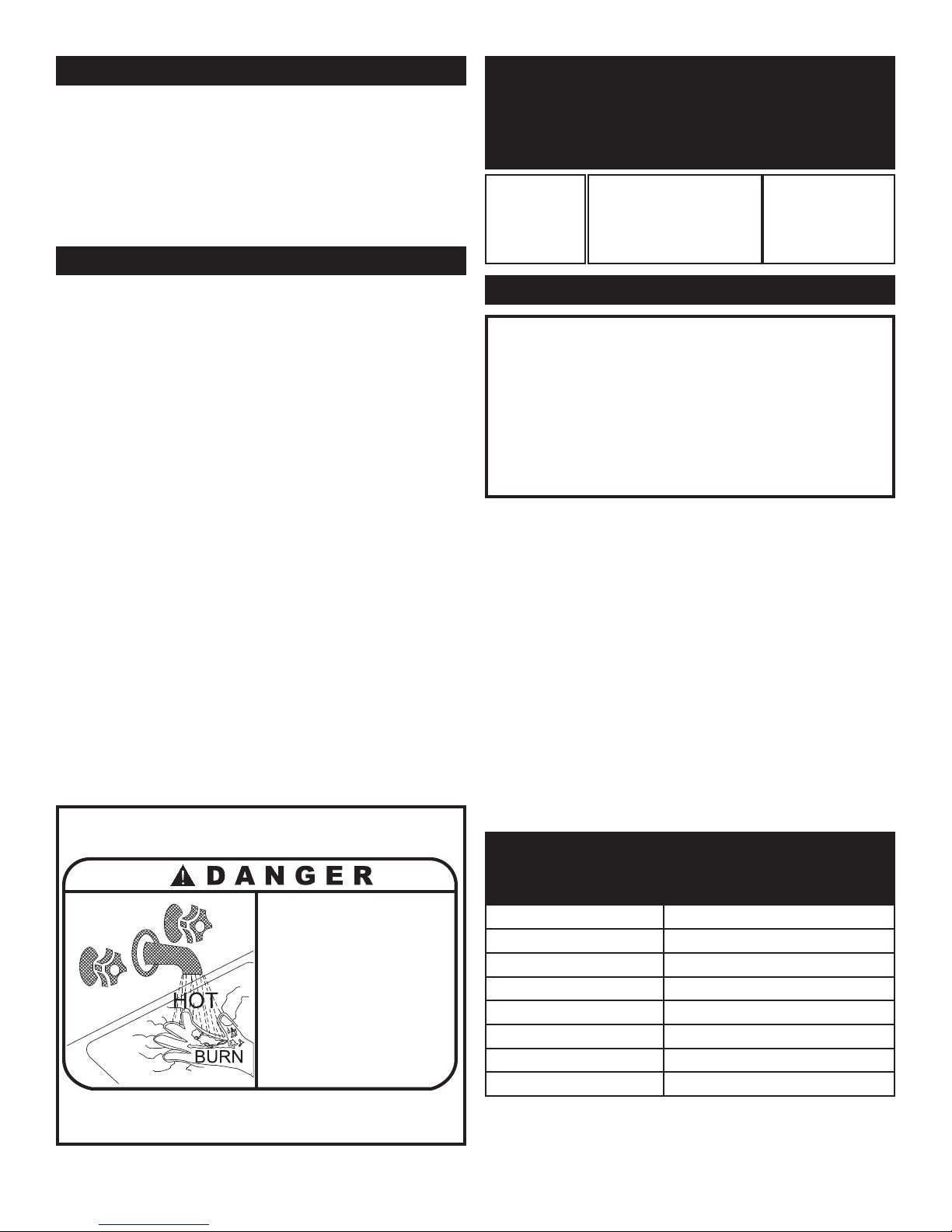
75
THERMOSTAT SETTINGS
1. The Excel 10 temperature con trol ler is adjusted
to a low test setting when shipped from the factory.
2. Using the Command Display, adjust the
temperature set point to the lowest settings which
will satisfy hot water demands and prevent a risk
of scald injury.
TEMPERATURE ADJUSTMENT
MINIMUM WATER TEMPERATURES
(Domestic Hot Water Use)
Inlet water temperatures below the specified minimum
recommendations can excessively cool the products of combustion
resulting in condensation on the primary heat exchanger. The water
heater is designed to condense only on the secondary heat
exchanger. Condensation on the primary heat ex chang er can cause
operational problems, bad combustion, sooting, flue gas spill age
and reduced service life of the related components.
A minimum water temperature has been established for each model
based on the Btu/hr input at 100% of rated burner input. The
temperature set point for the Excel 10 controller sensing stored
water temperature must not be set lower than the specified
minimum for each model. Maintaining inlet water temperatures to
the water heater equal to or higher than the specified minimum
ensures proper op er a tion of the bypass and allows all con den sate
formation to occur on the sec ond ary heat exchanger. A water
heater allowed to sustain operation at water temperatures lower than
the specified minimum may not provide enough heat from the
burner to maintain water temperatures in the primary heat
exchanger above the 130°F (55°C) dew point of flue products.
Operation of a water heater at a temperature below the spec i fied
minimum will result in non-warrantable operational problems from
the condensate formation on the primary heat exchanger.
FIG. 87 Warning Label
TABLE - II
Minimum Inlet Water Temperatures
Input Minimum Return Minimum
Btu/hr Temperature Setpoint
1,500,000
___________
1,700,000
___________
2,000,000
50°F (10°C)
____________________
50°F (10°C)
____________________
50°F (10°C)
105°F (40.6°C)
_______________
90°F (32.2°C)
_______________
70°F (23.9°C)
CAUTION
An appliance allowed to op er ate with return temperatures
set point below the specified minimum settings may ex peri ence operational problems with the operating controls and
safety switches, obstruction of the flue gas passages on the
primary heat exchanger, incomplete combustion and
possible flue gas spill age. Operation at lower than specified
water temperatures may cause hazardous conditions that
result in non-war rant able damage to the appliance.
The maximum temperature set point that can be programmed
into the Excel 10 controller from the Command Display for
water heater operation is 190°F (87.8°C). The Excel 10 control
is factory pre-set at approximately 120°F (48.9°C). Facilities
with small children or invalids may require 120°F (48.9°C) or
lower temperature setting to reduce risk of scald injury. Some
states may require a lower temperature setting. Check with
your gas supplier for local requirements governing the
temperature setting. Remember, no water heating system will
provide exact temperature at all times. Allow a few days of
operation at this setting to determine the correct temperature
setting consistent with your needs.
The following chart (Table JJ) details the relationship of water
temperature and time with regard to scald injury and may be used
as a guide in determining the safest water temperature for your
applications.
TABLE - JJ
APPROXIMATE TIME / TEMPERATURE RE-
LATIONSHIPS IN SCALDS
120°F More than 5 minutes
125°F 1 1/2 to 2 minutes
130°F About 30 seconds
135°F About 10 seconds
140°F Less than 5 seconds
145°F Less than 3 seconds
150°F About 1 1/2 seconds
155°F About 1 second
• Water temperature over 125°F (52°C)
can cause severe burns instantly or
death from scalds.
• Children, disabled and elderly are
at highest risk of being scalded.
• See instruction manual before
setting temperature at heating
appliance.
• Feel water before bathing or showering.
• If this appliance is used to produce
water that could scald if too hot,
such as domestic hot water use,
adjust the outlet control (limit) or use
temperature limiting valves to obtain
a maximum water temperature of
125°F (52°C).

76
NOTE:
(1) This water heater, when set at the lower temperature
setting, is not capable of producing hot water of sufficient
temperature for sanitizing purposes.
(2) Higher stored water tem per a ture increases the ability
of the water heater to supply desired quan ti ties of hot
water, however remember-
Incorrect piping of the cold water supply to the system may result
in excessive low temperature operation causing condensate
formation on the primary heat exchanger and operational problems.
The cold water supply piping must be installed in the discharge
piping from the heater to the storage tank. This allows the cold
water to be tempered in the storage tank before entering the heater.
See typical in stal la tion drawings provided with the unit for
correct piping. Higher water temperatures reduce the volume of
condensate formed.
CAUTION
Hotter water increases the risk of scald injury. Setting the
temperature selector to higher settings provides hotter water,
which increases the risk of scald injury.
The manufacturer recommends the use of a properly sized
thermostatic mixing valve to supply domestic hot water at
temperatures less than 110°F (43.3°C). Storing the water at a higher
temperature and thermostatically mixing the water will decrease
the size of the storage tank and increase the available quantity of
mixed hot water. Storing water at higher temperatures can help to
control the level of condensate formed and help prevent the growth
of water born bac te ria. Caution! Adequate care MUST be taken to
prevent potential scald injury when storing water at 140°F (60°C)
and hotter.
WARNING
Should overheating occur or the gas supply fail to shut
off, do not turn off or disconnect the electrical supply to
the pump. Instead, shut off the gas supply at a location
external to the appliance.
HIGH WATER TEMPERATURE
LIMIT CONTROL
A Manual Reset High Limit control is located on the left front of the
left front side of the control panel, beside the Command Display.
Additional switches, alarm in di cat ing lights and optional low water
cut-off control switches are also located on this panel. The setting of
this con trol knob limits maximum discharge water temperature. The
water heater or hot water supply boiler temperature limit control is
adjustable up to a fixed maximum set ting of 200°F (93°C). A red
reset but ton, located beside the knob, must be pushed whenever water
temperature has exceeded the set point of the manual reset limit. The
temperature of the water in the heat exchanger must drop a minimum
of 15°F (8.3°C) below the setting of the manual reset high limit control
before the reset function can be activated. A red indicating light is
illuminated when the water temperature exceeds the set ting of the high
limit control. A sta tus point alarm of Over Temp will be displayed in
the Command Display when water temperature exceeds the Setpoint
Temperature programmed into the Excel 10 control.
OPTIONAL RELIEF VALVE
This water heater or hot water supply boiler is normally supplied with
a temperature and pressure relief valve sized in accordance with
applica ble codes. Units may be supplied with an optional pressure
only relief valve. When a water heater or hot water supply boiler
equipped with this optional relief valve is piped to a separate storage
vessel, the storage vessel must have a properly installed temperature
and pressure relief valve which complies with local codes.
THERMAL EXPANSION
A relief valve that discharges pe ri od i cal ly may be due to thermal
expansion in a closed system. A water heater or hot water supply
boiler installed in a closed system, such as one with a backflow
preventer or check valve in stalled in the cold water supply, shall be
provided with means to control ex pan sion. Contact the water supplier
or local plumbing inspector on how to correct this situation. Do not
plug or cap the relief valve discharge!
CATHODIC PROTECTION
Hydrogen gas can be produced in a hot water system that has not been
used for a long period of time (generally two weeks or more).
Hydrogen gas is ex treme ly flammable. To prevent the possibility of
injury under these con di tions, we recommend the hot water faucet be
open for several minutes at the kitchen sink before you use any
electrical appliance which is connected to the hot water system. If
hydrogen is present, there will be an unusual sound such as air
escaping through the pipe as the hot water begins to flow. There
should be no smoking or open flames near the faucet at the time it is
open.

77
Ladder Diagram
1,500,000 - 1,300,000 - 2,000,000 Btu/hr Models
J
3
5
4
6
1
2
3
O
.
C
.
J1
J
2
3
2
1
J
4
P
RES
E
T
R
E
SE
T
C
HA
S
S
I
S
G
R
O
UN
D
G
N
D
P
U
G
PU
BL
Y
24
V
A
C
LW
C
O
PROB
E
T
~
~
~
~
~
~
~
~
~
~
~
~
O
A SENSOR
INLET SENSO
R
REAR
CO
M
M
UNICATION
CABLE CONN
E
C
T
ION
CO
N
T
RO
L
PANEL
COMMUNICATIO
N
CABLE
C
O
NNECTION
B
YP
AS
S
VA
LVE
NO
CO
M
L
OUVE
R
REL
AY
CO
NT
ACT
S
R
STD.
VFD POWER
RELAY
NO
COM
NO
C
POWER
SWITCH
N
R
3
2
7
VFD
M
BLOWER
ASSEMBLY
S1
L1
L2
S2
120VAC G A
S VALVE
NO
COM
NO
COM
EXT. GAS VALVE
VENT VALVE
OPTIONAL
24 VA
C
LOW VOLTA
GE
TR
A
N
SFOR
MER
120
VAC
B
a
c
k
S
e
l
e
c
t
C
O
MMAN
D D
ISP
LAY
EBUS
EBU
S
EARTH
2
4
V
A
C
24
V
A
C
NC
CO
M
NC
HI-LIM
I
T ALARM
RELAY
CO
M
OVER
T
EMP
INDI
CAT
OR
R
24VAC SOL ENOID V
ALVE
F
2
F
1
+
IG
N
ITIO
N
MO
DULE
11
10
9
6
4
3
2
1
N/A
T
H
P
I
L
V1
P
S
F
F
M/S
F
F
L
V2
RESET
8
7
5
M
V
IG
N
ITIO
N
R
ES
ET
OPTI
O
NA
L
Louver
P
r
o
v
in
g
Sw
Lo
w
Gas
Hig
h
Gas
Blocke d
Drain
NO
NC
C
NO
NC
C
NC
NO
C
N
O
NC
C
NO
NC
C
NO
NC
C
O
PTIONAL
IGNITION
MODULE
N
O
CO
M
R
HOT
SURFACE
IGNITER
V
F
D
ENABLE
J3
51
41
31
21
4
3
2
1
E
G
ND
GN
D
A1-
3
O
HM
G
ND
G
N
D
22
V
DC
O
UT
E
-
B
U
S
DI
-
4
GND
DI
-
3
DI
-
2G
ND
2
O
U
T
3
OUT
5
OUT
1
OUT
4
O
UT
6
OUT
7
OUT
E
-
B
U
S
J
AC
K
A1-
1
O
HM
A1
-
2
OHM
A1-
4
OHM
A1-
5
V
/
m
a
A1-
6
V
/
m
a
DI
-
1
2
4
VAC
2
4
VAC
COM
8
O
UT
L
E
D
Inl
e
t
W
a
t
e
r
S
e
n
s
o
r
By
p
a
ss
W
a
ter
S
e
n
s
o
r
S
/
S
OA
S
e
n
s
o
r
L
o
wAi
r/Bloc
k
D
rain
Hi
-L
o
Ga
s
/
L
ouve
r
Ou
tl
e
t
W
a
ter S
e
n
s
o
r
F
l
a
m
e F
a
il
u
re
L
o
w W
tr
F
l
o
w
Ga
s
V
a
l
v
e
HS
I
1
2
3
1
2
1
2
1
2
1
2
3
4
5
BYP
A
SS
SENS
O
R
O
U
T
L
E
T
SENS
O
R
I
N
L
E
T
S
E
N
S
O
R
E
N
AB
L
E
S
WI
T
C
H
O
A
SENS
O
R
2
1
CH
ASS
I
S
GROUND
RU
N/ST
O
P S
WITCH
24
VAC
HSI
1
2
2
3
4
5
6
7
8
9
1
1
2
3
6
5
78
9
10
11
31
30 29
28
26
2
7
25 24
23 22
21
20 19
1
8
17
16
BYPASS SENSOR
CO
MMUNICAT
IO
N
CABLE #
2
BK
BK
P
W
M
/
4
-
2
0
ma
Di
a
l
Al
a
rm
F
l
o
a
t
Cl
o
s
e
F
l
o
a
t
Op
e
n
I
gn
i
tion
E
n
a
b
l
e
n
/a
P
u
m
p
Relay
n
/a
CONTROLL
E
R
I
N
P
UT
S
I
NPUTS
1
1
1
1
1
1
23
G
O
UTLET
SENSO
R
OUT
P
UT
S
1
1
2
NO
COM
P
UM
P
REL
AY
PUMP MOTOR
PUMP POWER
120VAC 15AM P
NO
C
O
M
NO
AL
A
RM
RELAY
CO
M
AL
ARM
CONTAC
T
S
AL
ARM
24VAC OUT
AL
ARM
INDICAT
OR
SILE
N
CE
SWITCH
R
STD
.
STD
.
M
O
D
E
TI
M
E
BA
S
E
M
U
X
A
DD
R
MANUA
L
OVER-
RI
DE
SIG IN -
SIG IN +
24V Pwr
Com
mA Out
Volts Ou t
V
o
l
t
s
O
u
t
m
A
O
u
t
C
o
m
2
4
V
P
w
r
S
I
G
+
S
I
G
-
PWM
CONV
.
D
I
P SWITCH #5 ON
N
O
TIC
E:
F
AC
T
ORY
CALI
BRA
T
E
D
.
D
O NOT
AD
J
US
T.
T3
T2
T1
I
G
NITI
O
N REL
A
Y
HI-L
IM
IT
UNIT POW ER 120VAC 15AMP
CO
MMUN
I
CA
T
IO
N
CABLE #
1
2
G
A
S VALVE RELAY
A
IR
SWITCH
FL
OW
SW
I
TCH
CONTROL LER HSI
12
GROUN
D
CO
N
T
RO
LL
ER 2
4
VAC
12
1
2
3
CONTROLLE
R
INP
U
T
S
1
2
3
4
5
1
2
3
4
5
CO
N
T
RO
LL
ER
I
NPU
T
S
2
3
4
5
6
7
8
9
1
R
CONT
R
O
L
L
E
R
OUT
P
UT
S
L
OUVER RE
L
AY
CONTROLLER
VF
D
1
2
3
HOT
NEUTRAL
GROUND
GROUND
2
G
R
O
U
ND
1
13
3
G
L1
L2
GND
R
L
V
1
LV2
P
U
M
P
E
N
AB
L
E
GAS
ON
F
L
OW
F
L
AME
F
AI
L
URE
O
PTIONA
L
B
L
K
DRAI
N
L
O
A
I
R
L
O
U
VER
G
A
S
H
I
/
L
O
LBL20021
REV B
88
88
P
R
O
G
V
O
L
T
S
A
MP
S
H
E
R
T
Z
RU
N
F
WD
REV
L
1L2
T
1T
2T
3
S
N
K
S
R
C
0
1
0
2
1
4
1
1
D
I
P
S
W
I
TC
H
I
N
D
O
W
N
P
O
S
I
TI
O
N
1
5
WARNING:
To avoid possible shock hazard, disconnect power before servicing.
TES
T
S
W
I
TC
H
P
U
T
T
2
4
VAC
L
W
CO
O
O
/
B
K
M
O
P
TI
O
N
A
L:
50
Hz
Li
m
i
t
R
esi
st
or
1.
2K
O
hm
O
VERRIDE TOGGLE
SWITCH
TO PUM
P
RELAY
CO
IL
T
O
O
VERRIDE
TOGGLE
SWI
TCH

78
Wiring Diagram
1,500,000 - 1,300,000 - 2,000,000 Btu/hr Models
888
8
P
R
O
G
V
OL
T
S
A
MP
S
HE
RT
Z
RUN
F
W
D
RE
V
VFD
ENABLE
J3
E
G
ND
GND
A1-
3
O
H
M
G
ND G
N
D
2
2VD
C
O
U
T
E
-
BUS
D
I
-
4
G
N
DDI
-
3
D
I
-
2
GND
2
OU
T
3
O
U
T
5
O
U
T
1
O
U
T
4
O
U
T
6
O
UT
7
O
U
T
E
-
B
U
S
JA
C
K
A
1-
1
O
H
M
A
1-
2
O
H
M
A
1
-
4
O
H
M
A
1-
5
V/
m
a
A
1-
6
V/
m
a
D
I
-
1
24
VA
C
2
4
VA
C
C
O
M
8
O
U
T
LE
D
I
nlet Wa
te
r Sen
s
or
Bypass
Wa
te
r Se
nsor
S/S
OA Se
n
s
or
LowAi r
/Block Dra
in
Hi-LoG
a
s/
Louver
Outl
e
t W
a
te
r
Se
nsor
F
l
a
m
e
Fail
ure
L
o
w
W
tr Flow
Gas Va
l
v
e
H
SI
2
4VAC
H
SI
1
2
2
3
4
56
7
8
9
1
12
3
GY
GY
BL
31 30
29 2
826
2
7
25
24 2
3
2
2
21 20 19
18 17 1
6
Back Select
H
I-LIMIT
NO
COM
NC
BL/
BK
CO
M
NC
Y
BL
NO
COM
NO
PU
HI-LIMIT ALARM
R
ELAY
ALARM
R
ELAY
COM
COM
NO
C
OM
PUM
P R
ELAY
120
VAC
CIRCUIT
BREAKER
OVER TEMP
INDICATOR
ALARM
C
O
NTACTS
ALARM
24
VAC
O
UT
A
L
AR
M
I
ND
ICATO
R
R
PU
PU
BL
BL
/
BKB
L/BK
BL
PUMP MOTOR
M
M
O
D
E
T
I
M
E
BAS
E
M
U
X
A
DD
R
MANUA
L
OVER-
RIDE
SIG IN -
SIG IN +
24V Pwr
Com
mA Out
Volts Out
V
o
l
t
s
O
u
t
m
A
O
u
t
C
o
m
24V
P
w
r
S
I
G
+
S
I
G
-
PWM
CO
NV.
COMMAND DISPLAY
24 VAC
VFD POWER RELAY
NO
COM
G
W
BK
BK
G
W
P
NO
C
POWER SWITCH
N
Y
T
Y
EBUS
EBUS
EARTH
24VAC
24VAC
G
Y
BL
W
G
BK
BK
BK
W
BK/W
BK
BK/W
BK
B
K
B
K
B
L
T
P
U
O
G
Y
PU
Y
BL
PU
PU
B
L/W
Y
Y
BL/W
BL
/
W
O
O
B
L
BR
W
G
Y
PWM/4
-20m
a
Di
a
l
Al
a
rm
F
loa
t
Clos
e
Fl
oa
t
O
p
e
n
Ignition
Ena
b
le
n/
a
Pump R
e
la
y
n
/a
CONTROLLER
CHA
SSIS
G
ROUN
D
Y
W
SILENCE
W
BK
Y
BL
BL
LOW VOLTAGE
TRANSFORMER
BL/BK
120VAC
15AMP
120VAC
15AMP
TWO 15 AMP CIRCUITS
OR ONE 30 AMP CIRCUIT
UNIT POWER
P
UM
P
P
OWER
CHASSIS
GROUND
CHA
SSIS
G
ROUN
D
IGNI
TION RELAY
FLOAT
R
R
R
R
BYPASS COMMO
N
R
S
T
D
.
S
T
D
.
B
L
R
B
L/W
BL
BL
B
L
1
4
5
6
2
3
REAR WIR
I
N
G
CONN
E
CTION
S
3
2
1
3
2
1
4
5
LO
U
V
24VAC ALARM
OUT
BYPASS
VALVE
OP
TI
O
NAL
2
1
A
LARM
C
O
NTACTS
PU
B
K
BL
Y
O
PE
N
CO
MMO
N
CL
OSE
B
R
T
PU
PU
Y
BL/W
OA
SENSOR
G
INPUTS
1
D
IP SWITCH #5 ON
P
UMP
BL
BL
P
Y
1
2
3
NOTICE:
FACTO
R
Y
CALIBR
AT
ED .
DO NO
T
ADJ
U
ST.
SWITC
H
BR
BK
W
BL
GY
GY
3
2
7
A
L
AR
M
DR
IVE
1
1
1
1
O
UTPUTS
W
FLOAT CLOSE
W/BK
1
2
BK
BK
3
2
1
L
1L2T
1
T
2
T
3
S
N
K
S
R
C
LI
NE
N
E
UT
RAL
G
R
O
UN
D
0
1
0
2
1
4
1
1
B
K
W
G
G
N
D
D
I
P
S
WI
T
CH I
N
D
O
WN
P
O
SITI
O
N
T
3
T
2
T
1
1
5
Y
PK
P
G
Y
W
G
Y
T
O
FAN
G
W
B
K
J3
5
4
6
1
2
3
O.C.
J
1
J
2
3
2
1
J
4
P
R
ESE
T
R
ESET
CHA
S
S
I
S
G
R
O
U
N
D
O
G
N
D
PU
G
PU
TEST
SWITCH
LW
C
O
PR
O
B
E
T
~
~
~
~
~
~
~
~
~
~
~
~
O/
T
T
P
Y
TO
1.
2K
R
ES
I
S
TO
R
TO
M
ANUA
L
O
’
R
I
D
E
SW

79
Wiring Diagram (continued)
1,500,000 - 1,300,000 - 2,000,000 Btu/hr Models
50
Hz L
i
mit
Res
i
s
to
r
1.2
K
Oh
m
Y
TO
V
F
D
TE
R
M
I
NAL
NU
M
B
E
R
15
T
O
V
FD
TE
R
M
I
NAL
NUMB
E
R
14
O
P
TIO
NAL
50
H
z
LIM
I
T
R
ESI
S
TO
R
P
O
P
T
I
O
NAL
WARNING:
To avoid possible
shock hazard, disconnect power
before servicing.
O
PTI
O
NA
L
BK
BR
J
3
5
1
4
1
3
1
214321
G
ND
O
H
M
O
U
T
O
H
M
O
H
M
O
H
M
V/
m
a
V/
m
a
1
2
3
1
2
1
2
1
2
1
2
3
4
5
BYPASS
SE
N
S
OR
OUT
LET
SE
NSOR
I
NL
E
T
SE
NS
OR
E
NAB
L
E
SWI
T
CH
OA
SE
NS
OR
2
1
CHA
SSIS
GRO
UND
RUN/STOP SWITCH
2
1
2
1
2
1
2
1
65
789
1
0
11
O
A SEN
SOR
INLET SENSO
R
BYPASS
SE
NSOR
F2
F1
-
+
IGNITION
MODULE
24VAC GAS
VALVE
L
ouver
Pr
o
ving
S
w
AIR
S
WITCH
Lo
w
G
as
High
G
as
FLO
W
S
W
I
TC
H
Blocked
Dr
ain
FC-FC+
S1
L1
L2
S2/FS
L
I
N
E
N
E
U
T
R
A
L
11
10
9
6
4
3
2
1
N/A
TH
PI
LV1
PS
F
F
M
/
S
F
F
HOT
SURFACE
IGNITER
LBL90002 REV A
GY
BK
W
120VAC GA
S
V
AL
VE
Y
R
R
GAS VA
LVE RELAY
NO
CO
M
NO
COM
NO
NO
N
C
C
NC
NO
C
NO
NC
C
NO
N
C
C
N
O
N
C
C
EXT.
G
AS VALVE
Y
R
LV2
RESET
8
7
5
M
V
5
4
2
1
O
O/
BK
O
O
O
PU
PU
PU
R
R
R
O
BL
GY
M
T
BR
T
W
BK
W
BK
COMM
UNICATIO
N
CABLE #1
R
EAR
C
O
MMUNICATION
CABL
E
C
O
NNECTIO
N
CONTR
OL PANEL
C
O
MMUNICATION
CABLE
C
O
NNEC
TION
C
O
MM
UN
ICATION
C
ABLE #3
BYP
AS
S
VALVE
R
W
BK
GY
GY
GY
GY
NO
COM
LOUVER
RELAY
LOUVER
RELAY
CONTACTS
BLO
WER
ASSEM
BLY
R
O
T
A
T
I
O
N
R
O
T
A
T
I
O
N
STATUS
LED
BK
BK
Y
Y
Y
BK
Y
BR
BL
Y
BL/BK
BL
IGNITION
R
E
SET
BL
AT OPEN
BK
BK
R
OPT
I
ONA
L
VENT VALVE
OPTIO
N
A
L
OP
TIONAL
STD.
3
2
1
4
EXT. GAS
VALVE
VERS
LOUVE
R
CO
N
TACTS
CO
MMON
CLO
SE
D INPUT
OPEN INPUT
BK
W
120
VAC
O
UT
INLET
SENSOR
2
1
1
2
3
1
2
3
(2
)
Where poss
i
ble, swit
c
hes and circuitry ar e sh
ow
n in power
off s
tate
.
NOTES:
(3) When replacing wi
ring,
use
wire
of equal or h
ighe
r tem
pera
ture
and
ga
g
e.
(4
) Schematic shows
e
lec
trica
l connect
i
ons only.
Please
refer
to wiring diagram in
o
w
ner's manua
l fo
r r
o
uting an
d
pin-outs for all connector
blocks
.
(1
)
W
ARNING:
To
a
vo
id possible shock hazard
, di
sc
onnect po
w
er be
for
e se
r
v
icing.
BR
I
NPUT
S
1
1
1
1
1
BK
W
Y
BR
BL
R
NOTE:
DO NOT DI
S
CONN
EC
T
CABLE FROM
B
LO
W
ER.
G
OUTLE
T S
EN
SOR
COMMUNICATION
CABLE #1
1
PU
PU
PU
PU
Y
PU
PU
C
OMMUNICATION
CAB
LE
#2
PU
W
W/
B
K
(5) Pum
p
de
lay
is
standard on water
heaters
.
Y
OR
T
OGG
LE
S
WI
TCH
M
ANUAL
O
VERRI
D
E
C
1
2
Y
4
3
2
BK
W
R
R
B
K
W
BLOCKED
DRAIN
PU
COM
MO
N
T
B
R
BLOCKED
O
PEN
1
2
3
J3
P
U
24 VAC
O
NC
C
O/
BK
PU
BL
Y

80
8/09-Printed in U.S.A.
Revision Notes: Rev. 4 (IFB/IFW-i&s-04) reflects additional text on Page
39, changes made to Figures 47 & 48, Table AA (Page 51), and LBLs on
Pages 77-79.
Revision 5 (ECO #C02870) reflects changes made to the scald section,
pages 70, 73, and 75, the addition of a mixing valve to the piping diagrams
(FIG’s 83 - 86), edits made to FIG. 80 (pg. 66), and a title change on FIG.’s
3 and 4 on page 4.
Revision 6 (ECO #C04349) reflects the addition of a maintenance table
and a condensate testing section.
 Loading...