


Label Printer
User’s Guide
For All Series Printer s
Changing the way the world prints labels…

PROPRIETARY NOTICE AND LIABILITY DISCLAIMER
The information disclosed in this document, including all designs and related materials, is
the valuable property of IntelliTech International Incorporated (IntelliTech) and/or its licensors. IntelliTech and/or its licensors, as appropriate, reserve all patent, copyright and
other proprietary rights to this document, including all design, manufacturing, reproduction, use, and sales rights thereto, except to the extent said rights are expressly granted to
others.
The IntelliTech product(s) discussed in this document are warranted in accordance with the
terms of the Warranty Statement accompanying each product. However, actual
performance of each such product is dependent upon factors such as system configuration,
customer data, and operator control. Since implementation by customers of each product
may vary, the suitability of specific product configurations and applications must be
determined by the customer and is not warranted by IntelliTech.
To allow for design and specification improvements, the information in this document is
subject to change at any time, without notice. Reproduction of this document or portions
thereof without prior written approval of IntelliTech is prohibited.
IntelliBar is a trademark of IntelliTech International, Inc.
Copyright 1998 - 2012
IntelliTech International Inc.
43 Broad Street
Hudson, MA 01749
http://www.intellitech-intl.com
All Rights Reserved

Contents
Preface........................................................................................................................ xi
Abbreviations.............................................................................................................xiii
General Information
Models 48 and 412.....................................................................................................1-2
Model 88.....................................................................................................................1-3
Hardware Description...............................................................................................1-5
Power Supply......................................................................................................1-5
Control Panel......................................................................................................1-5
Main Board.........................................................................................................1-5
Ribbon and Label Feed Mechanisms.................................................................1-7
Print Mechanism.................................................................................................1-9
Memory Expansion..................................................................................................1-10
Options.....................................................................................................................1-10
User-Installable Options...................................................................................1-10
Factory-Installable Options.................................................................................1-11
Specifications.............................................................................................................1-12
Interface.....................................................................................................................1-14
Parallel Interface.................................................................................................1-14
IEEE 1284 Cable Requirements..................................................................1-14
Serial Interface....................................................................................................1-14
Data Transmission.......................................................................................1-15
Section 2 Setup
Unit Setup..................................................................................................................2-1
Connecting the Power Cord...............................................................................2-5
Connecting the Communicat i ons In t erface Cables............................................2-6
Label and Ribbon Requirements........................................................................2-10
IntelliBar Ribbons........................................................................................2-12
Ribbon/Label Combination................................................................................2-14
Loading Labels....................................................................................................2-15
Models 48 and 412.......................................................................................2-15

Contentsiv
Model 88.......................................................................................................2-23
Installing the T hermal Ribbon...........................................................................2-26
Model 48 or 412...........................................................................................2-26
Model 88.......................................................................................................2-30
Print Head Removal and Installation.......................................................................2-34
Print Head Removal...........................................................................................2-35
Model 48 and Model 412.............................................................................2-35
Model 88.......................................................................................................2-38
Print Head Installation.......................................................................................2-40
Model 48 and 412.........................................................................................2-40
Model 88.......................................................................................................2-41
Print Head Voltage Adjustment.........................................................................2-42
Section 3 Unit Operation
Controls and Indicators......................................................................................3-1
Self-Test...............................................................................................................3-4
Test Page......................................................................................................3-6
Bar Code......................................................................................................3-7
Menu Tree...........................................................................................................3-7
Default Factory Settings..............................................................................3-7
Changing Settings........................................................................................3-9
Controlling the Printer................................................................................3-20
LCD Display Messages.......................................................................................3-26
Printing Modes..........................................................................................................3-30
Standard Mode...................................................................................................3-30
Peel-Off Mode.....................................................................................................3-30
Tear-Off Mode....................................................................................................3-31
Cut-Off Mode......................................................................................................3-31
Section 4 Options
Memory Expansion....................................................................................................4-1
IntelliTech Internationa l Inc. O pti o ns......................................................................4-3
User-Installable Options.....................................................................................4-3
Factory-Installable Options.................................................................................4-3
Memory Expansion Module Installation (All Models).............................................4-4
Installing SIMMs................................................................................................4-7

Contents
v
Label Cutter Installation Procedure Overview (Model 48 and 412)
A. Remove the Standard Peel-Off Assembly (Model 48 and 412)
B. Install the Cutter Option (Model 48 and 412)
........................................4-14
C. Configure the Printer to Use the Cutter (Model 48 and 412)
Internal Rewinder (Model 48 and 412)
Loading Labels
....................................................................................................4-16
Loading Labels in Standard Mode
Loading Labels in Peel-Off Mode
.....................................................................4-16
..............................................................4-16
...............................................................4-19
......................4-11
............4-12
................4-15
Section 5 Cleaning and Adjustments
Cleaning.....................................................................................................................5-1
External Cleaning...............................................................................................5-1
Internal Cleaning................................................................................................5-1
Print Head...........................................................................................................5-3
Platen Roller........................................................................................................5-3
Sensors.................................................................................................................5-4
Print Position Adjustment.........................................................................................5-5
Print Head Voltage Adjustment................................................................................5-6
Correcting Poor Print Quality...................................................................................5-6
Print Head Adjustments.....................................................................................5-7
Media Mismatch.................................................................................................5-7
Density.................................................................................................................5-7
Resistance Value.................................................................................................5-7
Print Head Latch................................................................................................5-8
Print Speed..........................................................................................................5-8
Ribbon Guide Plate............................................................................................5-8
Bad Print Head...................................................................................................5-8
Mechanical Adjustments...........................................................................................5-9
Model 48 and 412..............................................................................................5-10
Label Width Guides (Model 48 and 412)..................................................5-10
Horizontal Print Head Alignment (Model 48 and 412)..............................5-11
Print Head Pressure Knob for Label Thickness (Model 48 and 412)........5-13
Print Head Balance Lever for Label Width Adjustment (Model 48
and 412)....................................................................................................5-14
Print Head Position Dial for Label Thickness Adjustment (Model 48
and 412)....................................................................................................5-15
Ribbon Guide Plate (Model 48 and 412).....................................................5-18

Contentsvi
Sample Adjustment......................................................................................5-19
Timing Belt Tension Adjustment (Model 48 and 412)...............................5-20
Model 88..............................................................................................................5-21
Label Width and Pressure Adjustment (Model 88)....................................5-21
Label Thickness Dial (Model 88).................................................................5-23
Ribbon Tension Plate (Model 88)................................................................5-24
Print Density Adjustment..........................................................................................5-26
Section 6 Troubleshooting
Troubleshooting the Problem....................................................................................6-1
Using LCD Display Error Messages..........................................................................6-2
Correcting Print Quality...........................................................................................6-6
Top-Level Problem Solving.......................................................................................6-8
Common Questions and Answers.....................................................................6-17
Fax Form.............................................................................................................6-24
Appendix A Packing
Glossary
Proprietary Notice and Liability Disclaimer

Preface
This IntelliBar User Guide contains the information necessary to set up and maintain the
IntelliBar Models 48, 412, and 88 bar code printers.
*
The manual is organized as follows:
A list of the abbreviations us ed in this manual follows the preface.
Section 1 General Information provides an overview of the IntelliBar printers. This
chapter explains the main features of the printers and their options. This section also lists
printer specifications.
Section 2 Setup describes how to set up the printer.
Section 3 Unit Operation describes control panel buttons, status messages, menus, and
memory settings for the printer.
Section 4 Options provides information on the various IntelliBar user and dealer
installable options, including installation procedures .
Section 5 Cleaning and Adjustments contains instructions for cleaning and adjusting the
printer.
Section 6 Troubleshooting provides troubleshooting aids that include error codes, test
samples, and troubleshooting procedures. This section also contains information on getting
service and support and printer warranty terms and limitations.
Appendix A Packing provides packing information.
The Glossary at the end of this manual provides a list of IntelliBar and bar code printing
terms and briefly defines each one.
NOTE:
For updates on IntelliBar printer
specifications and other information about
IntelliTech International, Inc. products, visit our
web site at http://www.intellibar.com.
*
"This information is subject to change wi thout notice. This information is provided "as is" wit hout either express or
implied warranty.
Intelli
Tech shall not be liable in any event for any special, indirect or consequential damages or any damages whatsoever
resulting from loss of data, profits or use, for any reason or in any action, arising out of or in connection with the use or
performance of this information. "
Intelli
Tech International, Inc. disclaims any and all warranties with regard to this information.

Abbreviations
xiii
Aampere
AC alternating current
ACK acknowledge
ASCII American Standard Code for
Information Interchange
BIOS basic input/output system
bit binary digit
bp i bits per inch
bps bits per second
C centigrade
CD carrier detect
CLK clock
cm cen timeter
CM OS complementary me tal oxide
semiconductor
COM communication
CPU central processing unit
cpi characters per inch
CTS clear to send
DACK DMA ackno wledge
FAX facsimile transmission
FCC Federal Communications
Commission
FG frame ground
FRU field-replaceable unit
GB gigabyte
GND ground
HEX hexadecimal
HM I h orizontal motion ind ex
HP Hewlett Packard
Hz hertz
IC integrat ed circuit
ID identification
in. inch
IPB illustrated par ts breakdown
I/O input/output
ips inches pe r second
IRQ interrupt request
ISO Internat ional Standards
Organization
DC direct current
DIP dual in- line pa ckage
DMA direct memory access
dpi dots per inch
DRAM dynamic RA M
DSR data set ready
DT direct thermal application
DTE data terminal equipment
DTR data terminal ready
EPROM erasable programmable
read-only memory
EEPROM electrically erasable
programmable read-only
memory
ETX end-of-text
F Fahrenheit
K kilo (1024)
k kilo (1000)
KB kilobyte
kg kilogram
kHz kilohertz
LAN local area network
lb pound
LCD liquid crystal display
LED light-emitting dio de
lpi lines pe r inch
LSB least-significant bit
Mmega
mA milliamps
max maximum
MB megabyte
MHz megahertz

xiv Abbreviations
mm millimeter
ms millisecond
MSB most-significant bit
NC not co nnected
NMI non-maskable interrupt
ns nanosecond
PC personal computer
PCB printed circuit bo ar d
PCL p rinter control language
PDL page descriptio n language
pixel picture element
p-p peak-to-peak
PROM programmable ROM
P.S. power supply
RAM random-access memory
ROM read-on ly memory
rpm revolutions per minute
Wwrite
*
R read
RD received data
RTS request to send
R/W read/write
Sslave
SD send data
SG signal ground
SIMM single inlin e memory mo dule
STB strobe
SW switch
TD transmit data
TG tag stock application
TSC Technical Support Center
TT thermal transfer applicatio n
TTL transisto r / transist or logic
tpi tracks per inch
Vvolt
Vdc volts, direct current
VRAM virtual RAM
Wwatt
*
"This information is subject to change without notice.
This information is provided "as is" without either express or implied warranty.
Inc. disclaims any and all warranties with regard to
this information.
event for any special, indirect or consequential damages or any damages whatsoever resulting from loss of
data, profits or use, for any reason or in any action,
arising out of or in connection with the use or performance of this information."
Intelli
Intelli
Tech International,
Tech shall not be liable in any

Section 1
General Information
Th e IntelliBar is a thermal label printer that us es ind ustry-sta ndard printer command
languages t o produce high-resolution fonts, graphics, and bar co des o n t hermal transfer or
direct thermal paper or s yn thetic rolls of labels o r tag stock.
Th e IntelliBar print er family consists of four series diffe rentiated by the printer comma n d
language, emulation, and connectivity as listed in Table 1-1.
Table 1-1 IntelliBar Printer Product Line
Series Name Pri nter Command
Language
IntelliBar Standard
Series
IntelliBar AS Series AFP/IPDS,
IntelliBar ax Series SCS,
IntelliBar LPR Series IGP/PGL, IGP/VGL
Hewlett Packar d
Printer Control
Language 5
(HP PCL5)
HP PCL5
HP PCL5
Magnum Code V,
HP PCL5
Emulation Connectivity
LaserJet III IEEE 1284 parallel,
RS-232/RS422C serial
IBM 4028 IEEE 1284 parallel,
RS-232/RS422C serial,
10BaseT Twinax or Coax
IBM 5020 10BaseT Twinax or Coax,
IEEE 1284 parallel,
RS-232/RS422C serial
Printronix,
Centronics,
QMS
10BaseT Twinax or Coax,
IEEE 1284 parallel,
RS-232/RS422C serial
Each series consists of three models: Model 48, Model 412 and Model 88. All models print
using either th e thermal transfer or dir ect thermal printing method d escribed later in this
section. As standard features, all printers have 300 x 300 dots per inch (dpi) print
resolution, par allel an d serial communicat ion ports, and label p eel- off ca pability. The
In telliB ar AS, ax , and LPR Ser ies have the ad ditional standard feature of twinax and coax
connectivity. Each model also features a control panel and LCD display for simple printer
installa tio n and use (see “Co ntr ol Panel” in this section).
The Model 48 and Mo del 412 print labels up to a maximum width of 4.37 inches (111 mm).
The Model 88 prints labels up to a maximum width of 8.65 inches (220 mm). Label length is
model and memory dependent. I n the Model 48 and Model 412, memory can be expanded
t o increase lab el leng th, overall printer per formance, and data throug hput. The I nte lliBar
automat ically senses label length at power-on and provides a backfeeding capability used
with tear-off, pee l-off, or cut -off printing modes.

1-2 General Information
Print output can include text and graphics in addition to high-density bar codes, ext ending
t he IntelliBar printer’s versatility for any label prin ting need .
Depending on t h e IntelliBar model and the ma in board revision, ot her feature s inclu de:
an operating speed of up to 8 inches per seco nd (ips) for the Model 48 and Model
88, and 12 ips for t he Model 412.
HP PCL 5 compatibility and LaserJe t III printer command set emulation with 14
bitmap and eight outline fonts ( in addition to specific printer command languages
fo r th e var ious Int elliBar printer series as describ ed in Table 1-1). Support
includes all PCL 5 commands and func tio n s wit h several additional co mmand
extensions to deal with special printer featur es that ar e no t available in the HP
LaserJet (see t he IntelliBar Programmer’s Reference Guide for more
information).
a minimum of 2 MB of random-access memory (RAM) expandable (in the Model
48 and Model 412) using SIMM option inst allation (see “Memory Expansion” in
t his section).
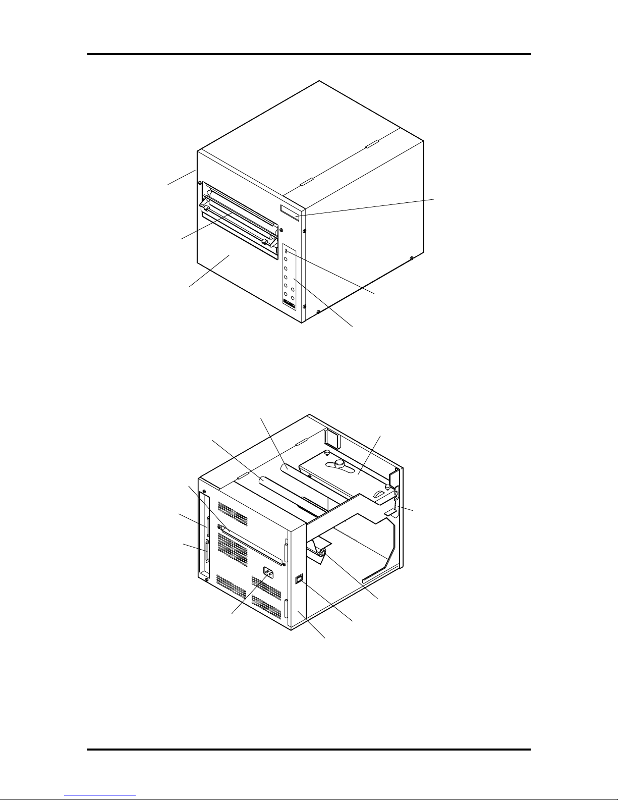
MODELS 48 AND 412
Features common to Models 48 and 412 are shown in Figure 1-1 and Figure 1-2 and
described in the following subsections. For printer specifications, see “Specifications” in this
section.
LCD Display
Lamps
Control
Pane l
Power Switch
Access
Handle
Label Release
Paper Slot
Label Exit
Slot
Front Panel
Figure 1-1 Model 48 and Model 412 Features (Front and Left Side View)

General Information 1-3
Left Side
Panel
External
Label
Entrance
Slot
Serial
Port
Parallel
Port
AC Power
Inlet
Power Supply
Label Supply
Spindle
Front Panel
Latch
Print Head
Print Head
Release Lever
Ribbon Takeup
Spindle
Ribbon Supply
Spindle
Figure 1-2 Model 48 and Model 412 Features (Rear and Left Side View)
MODEL 88
The features of the Model 88 are shown in Figure 1-3 and Figure 1-4 and described in the
following subsections. For printer specifications, see “Specifications” in this section.
1-4 General Information
Access
Handle
(hidden)
Label Exit
Slot
Front
Panel
Figure 1-3 Model 88 Feature s (Front and Right Side View)
Control
Panel
LCD Display
Lamps
Ribbon T ak eup
Spindle
Print Head
Label Supply
Spindle
Power Switch
Print Head
Release Latch
External
Label
Entrance
Slot
Serial
Port
Parallel
Port
Ribbon Supply
Spindle
AC Power
Inlet
Power Supply
Figure 1-4 Model 88 Features (Rear and Left Side View)
General Information 1-5
HARDWARE DESCRIPTION
Printer operat ions are coordinated by control panel settings and the main boar d components
under DC voltage from t he po wer supply. The fo llowing subsections describe how pr inting
is carried o u t.
power supply
co ntrol pa nel
main board
ribbo n and paper feed mechanisms
print mechanism (printer engine)
Power Supply
Alt er nat ing current (AC) is fed directly into the po wer supply and converted into the
various DC voltages that drive and cont r ol printer operat ion (+5 V, +12 V, - 12 V, +18 V,
+24 V). The power supply contains one replaceable fuse.
Control Panel
The contro l panel contains t he LCD display, power and alert indicators, and butto ns that
allow you t o cont rol and monitor printer operation. The 2-line display provides printer
status and err or messages and the printer settings menu tree. The power indicator shows
whether the printer is turned on or off, while the alert indicator shows whether the print er
has a fault or error condition that may affect o per ation. The co nt r ol panel buttons allow yo u
to view or change the printer settings (user parameters) via the menu tree.
For more infor mation, see Sect ion 3, “Unit Operation.”
Main Board
The main board (located behind the right side panel) controls communications between the
computer and printer engine and coor dinates the printer’s logic and mechanical functions.
The printing pro cess begins when t he co mputer sends dat a to the main board thro ugh either
the serial or parallel interface. T he main bo ar d r eceives and int er pr ets the data (HP LaserJet
emulation and HP PCL language), develops the data in RAM, transmits the data t o the print
head for thermal tr ansference, and coordinates the paper and ribbon feeding mechanisms.
Th e main boar d is fun ctionally divided into two a reas: t he main or control area fo r image
(video) processing and the sub area for engine contr ol and print processing.
Figure 1-5 and Figure 1-6 show t he locations of the connectors on each main board
revision.
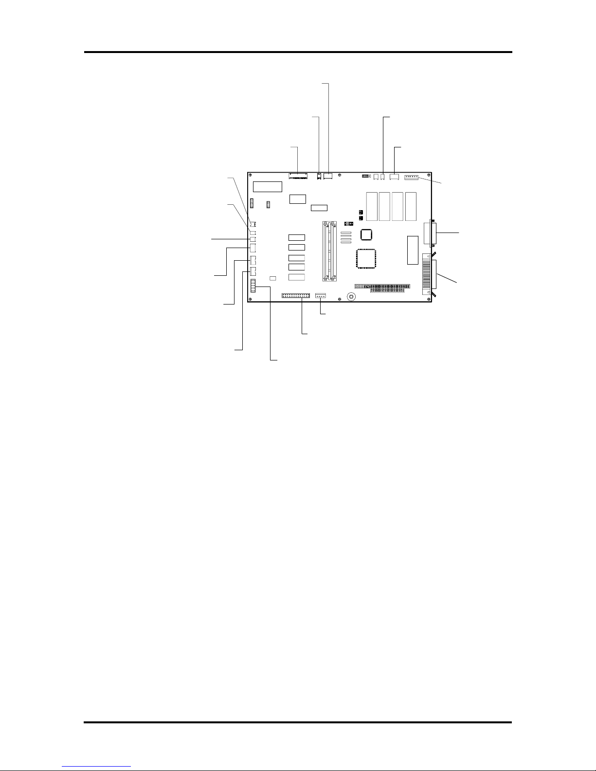
1-6 General Information
CN11 (Power)
6-pin
CN7 (Power)
2-pin
CN6 (Print Head)
14-pin
CN8 (Front Panel
Open) 4-pin
CN4 (Label Sensor Diode)
2-pin
CN3 (Label Sensor LED)
3-pin
CN2 (Label Cutter Option)
5-pin
CN1 (Ribbon Present)
4-pin
CN5 (Print Head Open
/Closed) 4-pin
CN13 (Control Panel Print Mode - Peel, Cut,
Rewind) 10-pin
CN12 (Power)
4-pin
P3 (Control Panel)
26-pin
CN14 (Model 412
Pre-Heater) 2-pin
CN17 (Stepper
Motor) 4-pin
CN16 (Stepper
Motor) 6-pin
P2 (Serial)
25-pin
P1 (Parallel)
36-pin
Figure 1-5 Main Board Revision 12, 13, or 14 Connector Locations
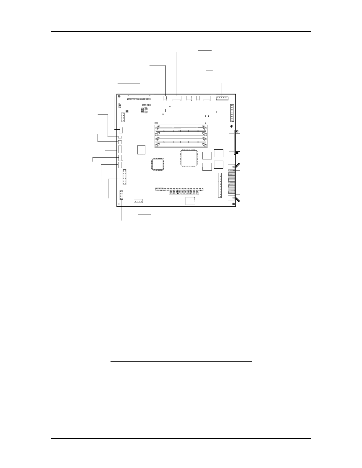
General Information 1-7
CN 6 (Print Head)
14-pin
CN 8 (Front P anel
O p en) 4-pin
CN 4 (Label S ensor
Diode) 2-pin
CN3 (Lab el
S ensor LE D )
3-pin
CN2 (Lab el
C utte r Optio n )
5-pin
CN1 (R ibbon
Present)
4-pin
CN 5 (Print Head
O p en/Closed
P3 (Control
Panel) 26-pin
CN13 (C ontrol P anel P rint M od e - P eel,
Cut, Rewind) 10-pin
CN 11 (P ow er)
6-pin
CN7 (Pow er)
2-pin
CN 12 (P ow er)
4-pin
CN14 ( Powe r fo r Mo del 412 Pre-Heater )
2-pin
CN17 (Stepper Motor
Power) 4-pin
CN 16 (S tepper
M otor) 6-pin
P2 (S erial)
25-pin
P1 (P arallel)
36-pin
Parallel Port Bus
Connector
Figure 1-6 Main Board Revision 15 and 16 Connector Locations
Ribbon and Label Feed Mechanisms
This section describes the thermal transfer printing process carried out by the ribbon and
label feed mech anisms.
NOTE:
ribbon is required a nd heat se nsitive labels or tag
stock are printed on directly, is not described in
t his section.
During the thermal tr ansfer process, the ribbon and label feed mechanisms move the ribbon
and labels between the platen and t hermal print head. T his confined space causes the ribbon
to pr ess against the label. Ink fro m the ribbon is applied to the label each time it crosses the
print head by the heating of individual print head elements (resistor s) . The combination of
heat from the resistors and pressure between t he ribbon and label lays down the printed
image.
Direct thermal printing, where no
1-8 General Information
The ribbo n is fed by the stepper mot or and is controlled by the main boar d and LED sensor
settings (ribbon end sensor).
During the printing process, t he label feed mechanism moves the label from the supply roller
to the thermal print head and platen. Labels are fed by the stepper motor and by friction
with the ribbon. Label feeding is coordinated by the main board, s ensor se ttings ( label
sensor), and the co nt r ol panel (see Section 3 for contro l panel settings that affect label
feeding).
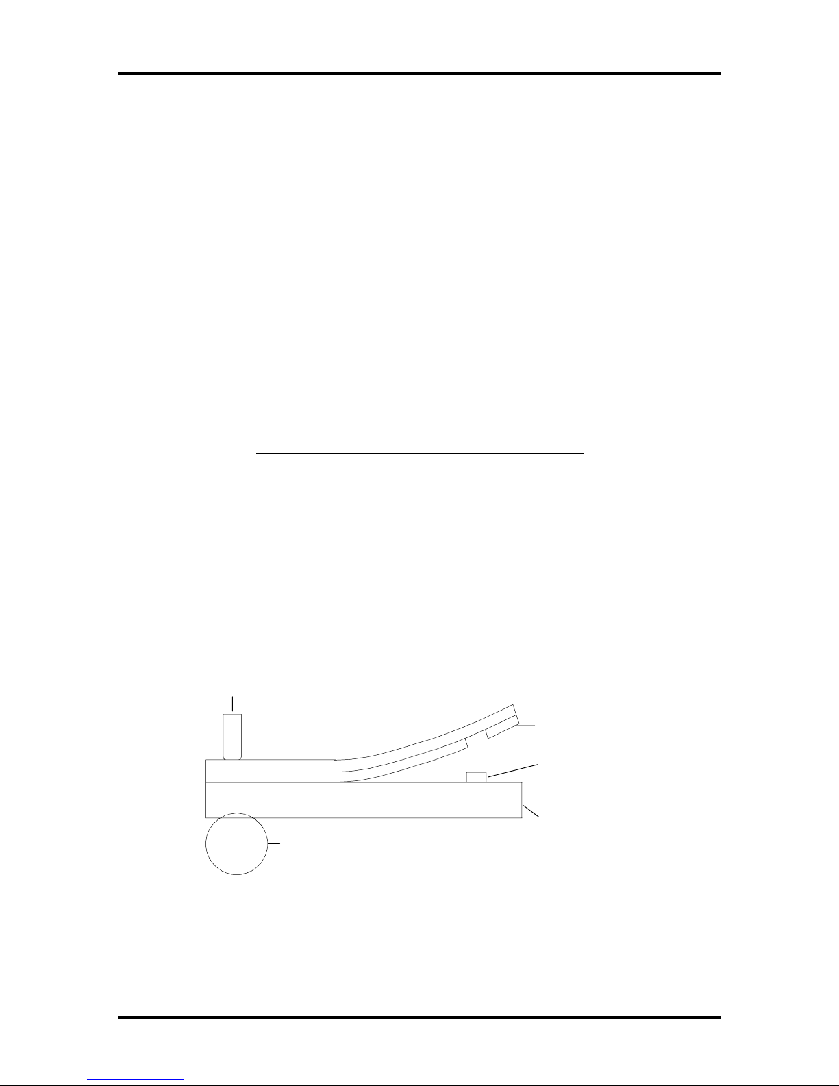
Figure 1-7 shows a simplified view o f how thermal transference works. A cut-away diagram
of the ribbon and label feed mechanism subassemblies for the Mo del 48 and 412 printers is
provided in Figure 1-8.
NOTE: The ribbon and label feed subassemblies
in the Model 88 printer differ in appearance from
the Model 48 and 412, but the theory of
operation is essentially identical as described
below.
When the label and ribbon are fed between the platen and thermal print head, the label
se nsor detects the loca tio n of the 0 .08 -inch (2 mm) minimum gap between the lab els o n the
paper roll and thus determines the pos ition of the first print line on t he label. A print
command is then sent to the thermal print head by the engine control processor on the main
board (see “Print Mechanism”).
Simultaneously, heat builds up in the thermal head heater, which contains a bank of resistor s
that selectively heat up, forming a printable image. The heat t r ansfers ink on the ribbon t o
areas on the label surface t hat correspond to the heat ed r esistors. This process fuses the
image to t he label.
Thermal Head
Thermal Transfer
Ink
Transferred Ink
Label
Platen
Figure 1-7 Thermal Transference
General Information 1-9
Ribbon Supply
Spindle
Stepper
Motor
Label Supply
Spindle
Figure 1-8 Ribbon and La bel Feed Mechanisms (Model 48 and 412)
Print Mechanism
Ribbon Take-Up
Spindle
Label Width
Guide
Print Head
(Open)
Label Exit
Slot
Sensor
Plate
Printer engine functions are controlled by t he engine control processor on the main board
sub-area. The engine control processo r sends cont rol signals in response t o commands and
data received from the computer via the PC/AT co r e. T he co ntr ol and data signals heat the
thermal print head element s ( r esisto r s) as previously described in “Ribbon and Paper Feed
Mechanisms.” Control and data signals from the engine control processor also drive the
stepper motor fo r feeding the ribbon and labels through the printer. When the label or
ribbon s ensors d etect that the printer has r un out of labels or ribbon (or w hen label jams
occur), the information is relayed from the engine control processor, and t he appropriat e
message appears on the contro l panel LCD (see Section 3 for display messages).
Depending on print speed, a specified “high” o r “low” voltage is sent from the power
supply to the heater inside the thermal print head. During normal speed printing (2.4 ips to
12 ips) typically used with wax ribbons, the power supply provides a “high” voltage of
approximately 24V. This vo ltage can be changed using the cont r ol panel menu buttons (see
“Print Head Volt age Adjustment” in Section 5).
During low speed printing (0.6 ips to 1.6 ips) typically used with resin ribbons, a “low”
voltage of approximat ely 12V is used. This voltage can also be changed using the control
panel menu buttons (see “Print Head Voltage Adjustment ” in Section 5).

1-10 General Information
Print speed is controlled by sending the appro pr iate st r obe (STB) pulse (STB1 or STB2
applied pulse) according to t he t emperatur e information sent from the print head thermist or.
For high speed printing (10 ips to 12 ips), the print head is pre-heat ed to an optimum head
temperature of 50o C per resistor. I f the head temperatur e exceeds 70o C, printing stops and
a head temperature message is reported on the control panel (see Section 2 for display
messages).
NOTE: During print ing, the actual temperature
of a resistor can exceed 200o C for a few
milliseconds.
MEMORY EXPANSION
Depending on t he main b oard revision installed in the printer, memory expansion ca n be
done in the Int elliBar Mo del 48 and 412 through the purchase of industry-standard, userinst allable, SIMM memor y modules made for Apple or PC products. SIMM modules are
available from retail or mail order compute r hardware suppliers. T h ese modu les install in
pairs in two expansion slots on the main boar d and increase the printer’s standard memory
capacity fro m the standard 2 MB to a maximum o f 10 MB.
NOTE: The Model 88 contains a total of 10 MB
o f sta ndard print er memory which is not
expandable.
See Table 4-1 and Table 4-2 in Sectio n 4 for memory installat ion guidelines and procedures.
OPTIONS
IntelliTech I nternational, Inc. option s for the Int elliBar printer ar e divid ed into two
categor ies: user-installable and factory-inst allable. Each cat egory is described below.
Section 4 provides additio nal information on IntelliTech International, Inc. printer options
(including installation procedures and dealer order numbers) .
User-Installable Options
Us er installable opt ions for the IntelliBar Models 4 8 and 412 include the following.
Label Cutter (Model 2401) — Let s you quickly print and process labels for
immediate application . This use r-installable opt ion fits in the front panel in pla ce
of the standard peel-off assembly. You must also remove the tear bar from above
the platen roller ( see Section 3 for label cutter installation procedures).

General Information 1-11
The cutter is designed for users who require on-demand label print ing (usually one
label at a t ime) and the convenience of a label precut and ready to apply. The
printer can be pro gr ammed to print a number of labels (up to 32, 767) and then
perform the cut function.
The cutter is designed to cut o nly paper or synthetic label backing (liner) and can
also c ut co ntinuous med ia that c ontains no rubber ba s ed adhesives.
NOTE: The maximum t h ickness of labels used
with the cutter option is 0.005 in. (0. 127 mm).
External Rewinder (Model 2402) — Mounts in front of the printer and rewinds
labels. Allows you t o output labels t hat can be conveniently spooled for storage or
shipment to anoth er location .
Factory-Installable Options
Fa ctory-inst allable option s for the IntelliBar Mode ls 48 and 412 include the following.
Internal Rewinder (Model 2405) — This option mo unt s inside the IntelliBar and
can be used to spoo l printed media (labels and backing paper) for convenient
stor age or transport ation o f labels in volume quantity. You can also use the
rewinder option to spoo l only the backing paper in peel-off print mode.
Reflective Label Sensor (Model 2404) — This field- or dealer-installable option
replaces the printer’s standard, t r ansmissive (see-through) label sensor. This
option reflects light off the black stripe when tag o r ticket stock is fed through t he
printer and thereby detects the label’s home position (used for determining the
first print line on the label). This option can also be used on butt-cut o r specialty
die-cut labels.
1-12 General Information
SPECIFICATIONS
Table 1-2 lists printer spec ificat ions for the IntelliBar St anda rd series. Specificat ions for the
In telliB ar AS Series, ax S eries, an d LPR Series are the s ame except as differ entiate d in
Table 1-1 for the printer command language, emulat ion, and connectivit y.
NOTE:
specifications and other informatio n about
IntelliTech International, Inc. product s, visit our
Web sit e at
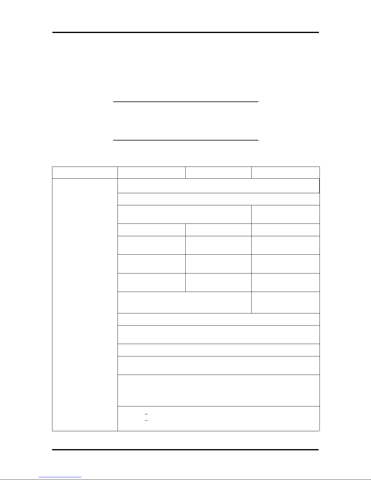
Table 1-2 IntelliBar Standard Series Specifications
Feature Model 48, 48E Model 412, 412E Model 88, 88E
Print method Thermal transfer or direct thermal
Resolution 300 x 300 dots per inch (11.81 dots per mm)
For updates on IntelliBar print er
http://www.intellibar.c o m
.
Print widths 4.37" (111 mm) maxim um) 8.65 in. (220 mm)
maximum
Print length (standar d)* 14 in. (356 m m) 28 in. (711. 2 mm) 14 in. ( 356 mm)
Print length
(maximum)*
Print speed .6 in. up to 8 in. per
Memory 2 MB standard, 10 MB
Dimensions 12.4 in. H x 9.4 in. W x 16 in. D
Control Panel LCD, 16 character, 2 line status and error displ ay
Interface IEEE 1284 (parall el) and RS-232C/RS-422C (serial)
Emulation Hewlett Packard LaserJet III (HP PCL 5, HP GL/2)
Fonts 14 bit map fonts, 8 AGFA IntelliFont scalable typefaces (CG Times, Univers
Bar codes UPC-A, UPC-E, EAN/JAN-13, EAN/JAN-8, UPC/EAN ext ension (2 of 5 digi t
99 in. (2,515 mm) 99 i n. (2,515 mm) 99 i n. ( 2,515 mm)
.6 in. up to 12 in. per
second
maximum
(315 H mm x 239 m m W x 406 mm D)
Bold)
supplemental), 3 of 9 ( Code 39), Extended 3 of 9, Interleaved 2 of 5, Code 128,
Codebar, Zip +4, Postnet, MSI Plessey, Code 93, Extended 93, UCC-128,
HIBC, PDF417
second
2 MB standard, 10 MB
maximum
Baud rate: 1200 - 38, 400 bps
.6 in. up to 8 in. per
second
10 MB standard (not
expandable)
13.2 in. H x 14.4 in. W
x 17 in. D (335 mm H x
366 mm W x 432 mm D)
Electrical 115 VAC + 10%, 50/60 Hz.
230 VAC + 10% 50/60 Hz
IEEE 1284 compl iant cable required
* See Section 2 for pri nt media specif ications.
General Information 1-13
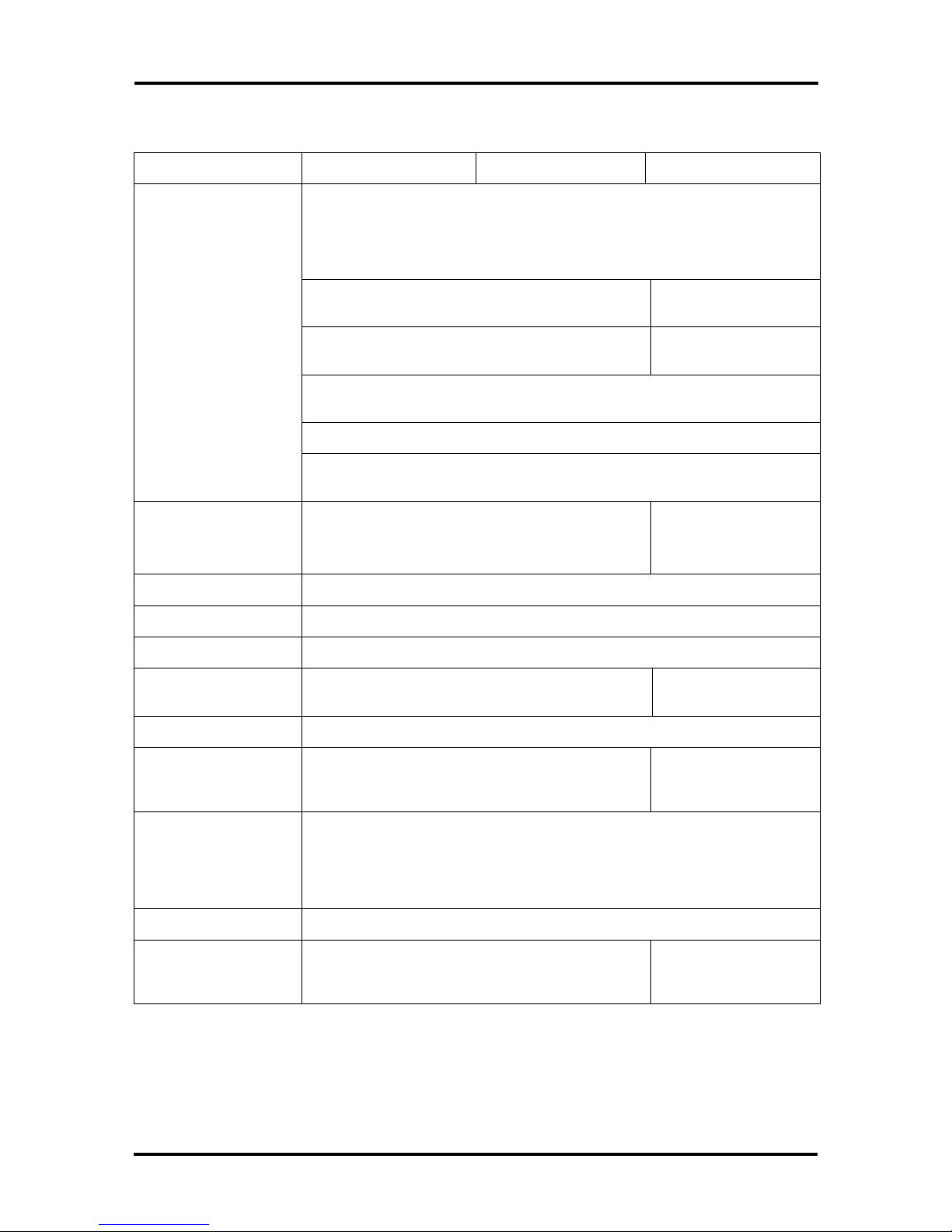
Table 1-2 IntelliBar Standard Series Specifications
Feature Model 48, 48E Model 412, 412E Model 88, 88E
Operating environment 41o F – 104o F (5o C – 40 C); below 85%
non-condensing humidi t y
Agency certifications UL-1950, C-UL, FCC Class A (115 VAC); TUV EN69050, CE mark (230 VAC)
User-installabl e options Label Backing Cutter: Model No. 2401**
External Label Rewinder: Model No. 2402
Factory-install ed
options
Warr ant y ( U. S) One-year l imited warranty; printhead warranted for 90 days or 500,000 linear
Media Die cut and continuous paper stocks, synthetic stocks, tag st ock, t icket stock
Label finishing Standard: Cont inuous, tear off and on-demand peel off (self strip). Cut off:
Label specifications Label print width: .75 in. min. to 4.37 in. max.
Reflective Sensor (Model 2404)
Internal Rewinder (Model 2405)
inches, whichever comes first
optional
(19 mm to 111 mm)
Label print length: .5 in. minimum . to 99 in. maximum *** (13 mm to 2,515 m m)
Minimum. label gap: .125 in. (3.2 mm)
Maximum label thickness: .01 i n. (.245 mm)
Maximum roll diameter: 8 in. (203 m m); 7 in.(178
mm) with Internal Rewinder installed
Inner core diameter: 3 in. (76. 2 mm)
Label Cutter: 240X
Reflective Sensor 240X
Internal Rewinder 240X
4.37 in. m inimum to
8.65 in. m aximum
(111 mm to 222 mm)
8 in. (203 m m)
Label web width: .75 in. m in. to 4.56 in. max.
(19 mm to 116 mm)
Ribbon types Express W ax for hi gh- speed printing up t o 12 inches per second
Dura Wax for econom ical printing
Rugged Resin for durability and smudge resistance
Dura Resin Plus for chemical, heat and scrat ch r esistance
Dura Wax/Resin for monochromatic color pri nt i ng
Ribbon length Wax Ribbons: 1, 475 f eet (450 m eters); Resin Ribbons: 984 f eet (300 m eters)
Ribbon widths 1.06 in., 2.12 in. , 3.27 in., 4.37 in.
(27 mm, 54 mm, 83 m m, 111 mm)
** Not int ended for use with rubber-based adhesives.
*** Wi t h addi t ional optional memory i nst alled and page protect turned off.
4.56 in. m in. to 9.5 in.
max. (116 m m to 241
mm)
4.37 in., 7 i n. , 8. 65 in.
(111 mm, 178 mm, 222
mm)

1-14 General Information
INTERFACE
This section descr ibes IntelliBar interfaces for communicating with the host computer or
network co mputer. T he printer is equipped with two interface communication ports:
36-pin IEEE 1284 parallel (connector P1)
25-pin RS-232C serial/RS-422 serial (connector P2)
To select the interface, use the control panel menu tree as described in Section 3.
Parallel Interface
This section descr ibes the IntelliBar parallel por t interf ace.
The IEEE 1284 parallel input allows no parameters. It always accepts 8-bit data with no
parity. For communication functions, it reserves the same set of characters reserved by the
serial po r t, wit h t he exception of X-ON and X-OFF characters.
Note that the IEEE 1284 parallel interface is essentially an input- only channel. The parallel
port communicat es in one direction, which is from the host computer to the printer.
IEEE 1284 Cable Requirements
The cable co nnected to the parallel int er face port must be fully shielded and fitted with t he
proper connector shell. Keep parallel cables as shor t as possible (8 ft. maximum) and do not
rout e or connect them near electrical conduits or high-voltage po wer lines.
To ensure the cable meets IEEE 1284 specifications, a cable labeled IEEE-1284 compliant
is required and is a simple wa y to guarantee good cable desig n . A cable with this label
contains the IEEE 1284-standard of 36 twisted-pair wires and is properly shielded.
Serial Interface
This section descr ibes the IntelliBar serial interface. I nt e lliBar serial co mmunica tio ns meets
the follo wing specifications:
asynchronous
8 data bits per character
no p arity
one start bit
one stop bit
Three parameters are used to control serial communicatio n: channel, baud rate, and
options.
General Information 1-15
The baud rate is given as an integer (such as 1200 or 9600), and t he maximum supported
baud rate is 38,400 bits per second (bps). Standard baud rates suppor ted by the IntelliBar
are as follo ws.
300
600
1200
2400
4800
9600
19,200
38,400
Data Transmission
The printer uses Robust X–ON/X–OFF prot ocol to contro l transmitted and received
character flow.
At power-on, the serial contr oller carries out communicat ion as soon as the hardware and
software are initia lized. Hence, the first cha racter sent in X-ON/X-OFF mode will be X-ON
(rather than X-OFF).
Available in Menu Mode using the control panel menu buttons, Robust X-ON/X-OFF flow
cont rol det ermines if ad ditional X-ONs should be transmitted.
If Robust X-O N/X-ON is set to ON (th e default), additional X-ONs will be transmitted at
one second intervals unt il data is received. I f it is set to OFF using the control panel (see
Section 3), no additional X-ONs are sent.
NOTE: Th e information in this section is subject
to change without notice. This information is
provided "as is " wit hou t either express or implied
warranty. IntelliTech International, I n c. d isclaims
any and all warranties with regard to this
information. IntelliTech shall not b e liable in any
event for any special, indirect or consequential
damages or any damages whatsoever resulting
from loss of data, profits or use, for any reason
or in any action, arising out of or in connection
with the use or performance of this information.

Section 2
Setup
Th is section provides p rint er setup information, wh ich includes inst ruc tio n s on connecting
power and interface cables, replacing the thermal ribbo n, and replacing the label roll. See
Sect ion 3 for in struction s on in sta lling memory a nd printer opt ions.
In additio n, t his section includes instructions on printin g test labels to chec k pr inter
operat ion before performing service or as a check after performing service.
Th is sec tio n also provides information on using the p rint er’s con trol pa nel buttons to affect
operat ion. Contr ol panel LED indicators, status messages, menu descriptions, and factory
settings of printer operating parameters are described. The 2-line by 16-charact er liquid
crystal display (LCD) on the control panel shows the printer’s operational stat us, error
codes, and parameter values. The LCD also displays the menus used t o change printer
parameters.
UNIT SETUP
Printer operat ion and print quality are affected by the environment in which the printer is
placed. When setting up the printer or do ing any service procedure, always be sure the
printer meets the environmental specifications listed below and the media specifications in
Section 1 of this manual. If the print er has not yet been unpacked (or t o repack it for
shipping), see Appendix A fo r unpacking/packing procedur es.
Th e IntelliBar is designed to function reliably even under ha rsh c onditio ns, s uch as th ose
that might be present in manufact ur ing or warehouse environment s.
Optimu m print quality is achieved under the follow ing condition s:
Temperature: 41° to 104° F (5° to 40° C)
Relative humidity: 15 to 85%
To maintain the best conditions for trouble-free operation, observe t he following
enviro nmental standards.
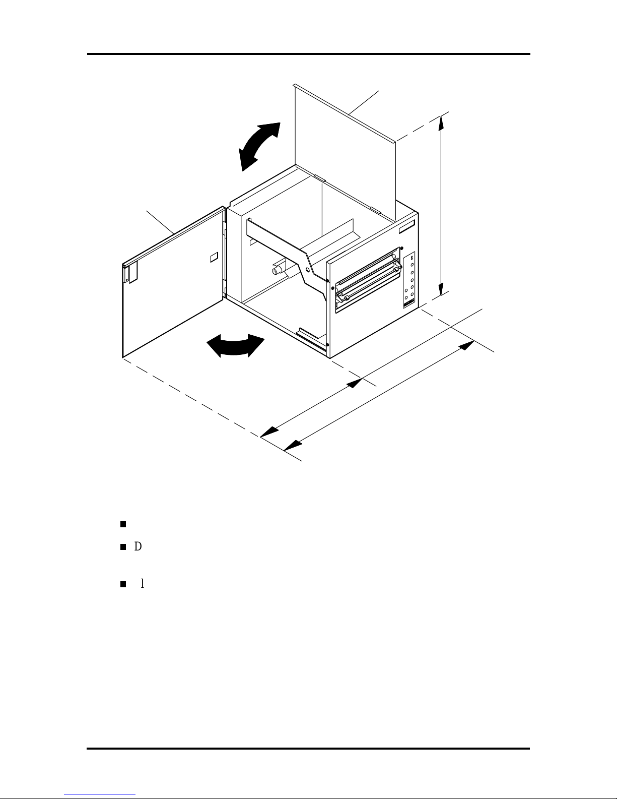
Place the printer in a well-ventilated area. Adequat e clearance should be provided
on all sides of the unit to allow heat to dissipate.
A minimum of 14 inches of clearance is needed above the Model 48 and 412
printers to open the hinged access door o n t he left side of the unit. Fo r the Model
88, a minimum of 11 inches is needed to open t he t op cover.
2-2 Setup
Note the printer dimensions and the clearance guidelines shown in the fo llowing
figures.
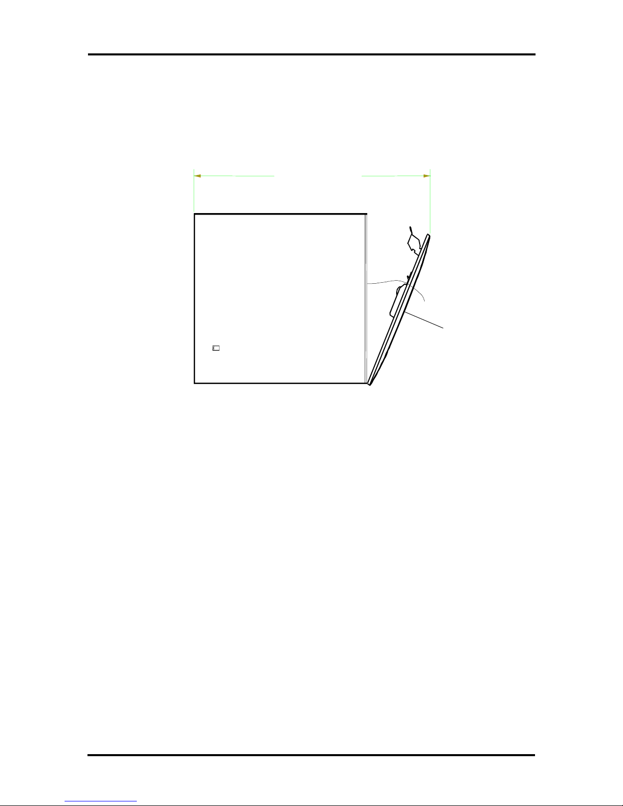
Wit h t he front panel open on the Model 48 and 412, the dist ance from the front of
the printer to t he back (printer depth) is 24.5 inches
24.50 Inches
Front Panel
Figure 2-1 Printer Depth (Model 48 and 412)
With the left side cover open, t he distance from the left side of the Model 48 and
Model 412 to the right side (printer width) is 17 inches.
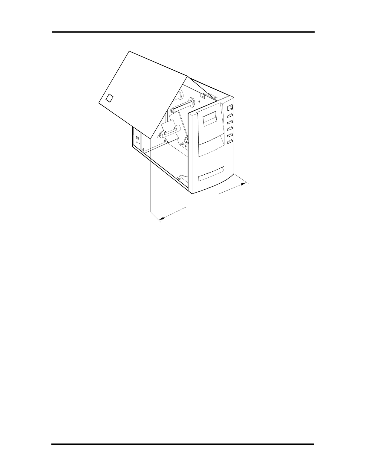
Setup 2-3
17.00 Inches
Figure 2-2 Printer Width (Model 48 and 412)
With the left side cover completely open, the distance from the bott om of the
Model 48 and Model 412 t o the top (printer height ) is 24.25 inches.
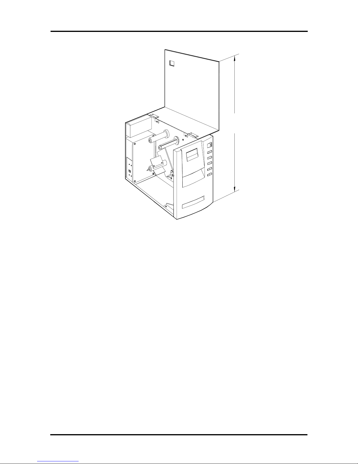
2-4 Setup
24.25 Inches
Figure 2-3 Printer Height (Model 48 and 412)
The following figure shows the width and height specifications fo r the Model 88
printer with the top and side covers open.
Top Cover
Setup 2-5
Side Cover
16.5"
30.5"
Figure 2-4 Printer Clearances (Model 88)
25"
Keep the printer away from direct sunlight.
Do not expo se the printer to extreme changes in temperature, as might occur near
a heating or air condit ioning unit.
Place the printer away from devices that generate str ong magnetic fields such as
electric mo tors or t ransformers.
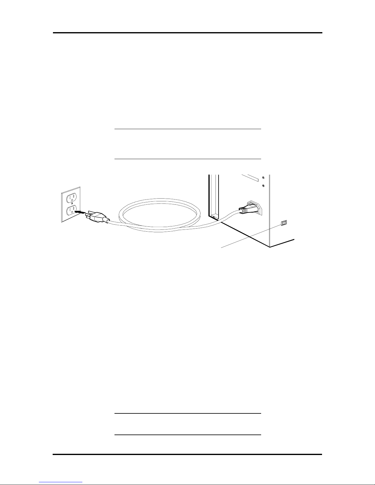
Connecting the Power Cord
The power cor d supplied with the printer plugs into the ac inlet connector on the back of
the printer. The ot her (male) end of the power cord plugs into a properly grounded, threeprong wall receptacle or other grounded po wer outlet. Always ensure the power switch is in
the OFF position before plugging in the cord. Figure 2-5 shows the location of the power
cord inlet connector and power switch and explains the power switch markings.
2-6 Setup
Th e power source for the IntelliBa r is either 110Vac ±10%, 50/60Hz or 220Vac ±10%,
50/60Hz (for “E” Versions). Voltage higher or lower than specified can cause printer
malfunctions.
The electric power line should be free fro m electric noise caused by other machines. A
dedica ted power line for th e IntelliBar, separate fr om noise p roducing equipmen t, is
reco mmende d and must be in close pr oximity to the pr in ter. I f a separate line (for e xample,
a different wall receptacle) is not available, use a noise filter (pur chasable from an electrical
supplies dealer).
CAUTION: Turn off the printer before plugging
in the power cord, and always use a properlygrounded power outlet.
Power Switch
0=Off
1=On
Figure 2-5 Connecting Power
Connecting the Communications Interface Cables
The following subsections describe how t o install the communications int er face cable in the
In telliBar s tandar d, AS Series, and ax S eries printers.
Standard IntelliBar Communications Interface
The back of the print er has one RS-232C/RS - 422 serial inter face port and one Cent r onics
parallel interface port.
Figure 2-6 identifies the interface port s.
When plugging in the interface cable, observe the alignment shape of the connectors to
ensure proper co nnection.
CAUTION: Turn off the computer and printer
before installing or removing any interface cable.

Rear Interfac e
Panel
Serial Port
Parallel Port
Setup 2-7
Figure 2-6 Interface Ports (Standard IntelliBar Series)
Use the correct type of interface cable when connecting the printer to the computer. A
description of each interface type is provided in Section 1 (see “Int er face”). Attach the
interface cable as follows.
1. Make sure the power to the printer is turned off.
2. Connect the interface cable t o the appropriate standard Int e lliBar Ser ies interface
port ( see Figure 2-6).
3. Secure the cable with the indicated screws o r clips.
For example, the RS-232C serial cable has two screws attached to the cable
connector.
4. If a grounding wire is att ached t o the interface cable, secure the wire to the one o f
the screws on the printer’s rear interface panel (see Figure 2-6).
5. Co nnect t he o ther end o f the interface cable to the computer according to the
manufactur er ’s instructions.

2-8 Setup
IntelliBar AS Series and ax Series Communication Interfaces
For IBM AS/400 and System 3X computers, set up t he IntelliBar printer to op erate in an
AFP/IPDS (AS Series) or SCS/EBCDIC (ax Series) configuration as follows:
1. Attach the twinax or coax cable adapter to the 15-pin port on t he interface board
(see Figure 2-7).
2. If connecting to a twinax host, set the I/O address o n t he four-segment switch
bank to the cor r ect value for your configuration (see Table 2-1). Obtain
information about your configuration’s address from your system administrato r.
If connecting to a coax host, set all the switches to OFF.
Table 2-1 IntelliBar AS Series I/O Address
Switch Settings (Twinax Connection)
Twinax
Address
0 Off Of f Of f Off
1 On Off Off Off
2 Off On Off Of f
3 On On Off Off
4 Off Of f On Off
5 On Off On Off
6 Off On On Of f
Figure 2-7 shows a clo se- up view of the rear of the printer with the int er face
Switch
Segment 1
Switch
Segment 2
Switch
Segment 3
Switch
Segment 4
board installed.

Interface
Board
LED
Setup 2-9
Interface Board
Switch Bank
Interface Board
IEEE 1284 Parallel Port
5 mm Hex Nut
Interface Board
RS232C Serial Port
(9-pin)
5 mm Hex Nut
Interface Board
Twinax/Coax Port (15-pin )
5 mm Hex Nut
Main
Board
LED
Main Board RS232C/422
Seria l Port
Main Board IEEE 1284
Parallel Port
Figure 2-7 Interface Board Connector, LED, and S w itch Locations
4. Turn on the printer and the host computer. After approximately 8 to 10 seco nds,
the LED on the interface board lights gr een, indicating that the host has
es tablished communication wit h the printer.
5. Check the status of the printer at the host. The host automatically co nfigures the
printer for AFP/IPDS (AS interface boar d installed) or SCS (ax interface boar d
installed).
After auto configuration, the print er is ready to receive print jobs.

2-10 Setup
Label and Ribbon Requirements
Print quality depends on fact ors such as the t ype of ribbo n and labels being used. Label
thickness and abrasion levels and the resistance of ribbo ns and labels to extreme
t emperatures all play an important role in maintaining the life of the print head and ensuring
print quality.
For best results , use high-qu ality la bels (die-cut, butt-cut, or contin uous forms) that mee t
the specifications listed in Table 2-2.
Table 2-2 Label Specifications
Measurement Minimum Specification Maximum Specification
*
Width
Model 48, 412: 0.75 in. (19
mm)
Model 48, 412: 4.56 in.
(116 mm ) maximum
Model 48, 412: 4.56 in. (116
mm)
Length 0.51 in. (13 mm) 99 in. (2.51 m); requires
Thickness 0.0025 in. (0.0635 mm) 0.01 in. ( 0.245 mm)
Gap 0.125 in. (3.2 mm) 1.5 x length of label
*Label specifications depend on the label stock. Maximum widt h of adhesive label stock (i ncluding backing
paper) or tag stock is 4.56 in. (116 mm) for the Model 48 and Model 412 and 9.5 in (241 m m) for the Model
88. Figure 2-8 provides label specifications for die-cut labels only. Maximum width of the print line (pri nt abl e
width) on the label is 4.37 i n. (111 mm) for t he Model 48 and Model 412 and 8.65 in. (220 mm) for the Model
88.
NOTE:
For updates on IntelliBar lab el
Model 88: 9.5 in.
(241 mm ) maximum
additional memory
specifications and other informatio n about labels
orderable through IntelliTech International, Inc.,
visit o ur Web site at
http://www.intellibar.c o m
.

.08 inches (2mm)
(
)
Unprintable Area
Top and Bottom
4.56 inches (116 mm) maximum web
width (Model 48 and 412)
9.5 inches (241 mm) maximum web
Model 88
width
AAAAAAA.......................................AAAA
Setup 2-11
Printable widths:
4.37 inches
(111 mm) maximum
(Model 48 and 412)
8.65 inches
(222 mm) maximum
(Model 88)
.5 inches (13mm)
Min. Label Length
for die-cut labels
99 inches (2.51m)
Max. Label Length
for die-cut labels
.125 inches
(3.2 mm) Min.
gap for die-cut
labels
Label Web W idth
Figure 2-8 Paper Specifications

2-12 Setup
IntelliBar Ribbons
In telliTech Int erna tio nal, Inc. offers t hree categories of thermal transfer ribbons:
wax (IntelliTech Express Wax ™ and IntelliTech D ura Wax™)
wax/r esin (IntelliTech D ura W ax/R esin™
resin ( Int elliTe ch Rugged Resin™ and Dura Resin Plus™).
Each category is manufactured with high quality materials to the following specifications to
fit par ticular operat ing conditions and purpo ses:
thickness – 5 microns
rib bon backing mater ial – polyester film
ink mate rial
— Express Wax, black
— Dura Wax, black
— Dura Wax/Resin, co lors (see Table 2-4)
— Rugged Resin, black
— Dura R esin Plus, black
ribbon length – 990 ft. (300 m) fo r r esin type; 1485 ft. (450 mm) fo r wax type
ribbon widths – Model 48 and 412 Model 88
1.06 in. (27 mm) 6.64 in. (165.0 mm)
2.13 in. (54 mm) 8.65 in. (220.0 mm)
3.27 in. (83 mm
4.37 in. (111 mm)
Th e following tables list IntelliTech order n umbers for IntelliBar black a nd color ribbons.

Setup 2-13
Table 2-3 IntelliBar Black Ribbons∗∗∗∗
Description Width Length Order Number
Ex pr ess Wax 1.08 inches (27 m m) 450 meters (1,475 feet) 50-101
2.20 inches (54 m m) 450 meters (1,475 feet) 50-102
3.32 inches (83 m m) 450 meters (1,475 feet) 50-103
4.44 inches (111 m m) 450 meters (1,475 feet) 50-104
6.64 inches (165 m m) 450 meters (1475 feet) 50-201
8.88 inches (222 m m) 450 meters (1,475 feet) 50- 202
Dura Wax 1.08 inches (27 m m) 450 meters (1,475 feet) 50-101
2.20 inches (54 m m) 450 meters (1,475 feet) 50-102
3.32 inches (83 m m) 450 meters (1,475 feet) 50-103
4.44 inches (111 m m) 450 meters (1,475 feet) 50-104
6.64 inches (165 m m) 450 meters (1475 feet) 50-203
8.88 inches (222 m m) 450 meters (1,475 feet) 50- 204
Rugged Resin 1.08 inc hes (27 mm) 300 met er s (990 feet) 50-109
2.20 inches (54 m m) 300 meters (990 feet) 50-110
3.32 inches (83 m m) 300 meters (990 feet) 50-111
4.44 inches (111 m m) 300 meters (990 feet) 50-112
6.64 inches (165 m m) 300 meters (990 feet) 50-205
8.88 inches (222 m m) 300 meters (990 feet) 50-206
Dura Resin Plus 1.08 inches (27 mm) 300 meter s (990 feet) 50-113
2.20 inches (54 m m) 300 meters (990 feet) 50-114
3.32 inches (83 m m) 300 meters (990 feet) 50-115
4.44 inches (111 m m) 300 meters (990 feet) 50-116
6.64 inches (165 m m) 300 meters (990 feet) 50-207
8.88 inches (222 m m) 300 meters (990 feet) 50-208
∗
This page was prepared September 1999. For an up-to-date listing of IntelliBar ribbons, please call
800-694-3034.
Intelli
Tech at

2-14 Setup
Table 2-4 IntelliBar Color Ribbons∗∗∗∗
Description Color Width Length Order Nu mber
Dura Wax/Resin White 1.08 inches (27 mm) 300 met er s (990 feet) 50- 501
White 2.20 inches (54 mm) 300 meter s (990 feet) 50- 502
White 3.32 inches (83 mm) 300 meter s (990 feet) 50- 503
White 4.44 inches (111 mm) 300 meter s (990 feet) 50- 504
White 6.64 inches (165 mm) 300 meter s (990 feet) 50- 505
White 8.88 inches (222 mm) 300 meter s (990 feet) 50-506
Process
cyan
Process
cyan
Process
cyan
Process
cyan
Process
cyan
Process
cyan
Process
magenta
Process
magenta
Process
magenta
Process
magenta
1.08 i nc hes (27 mm) 300 met er s (990 feet) 50- 508
2.20 i nc hes (54 mm) 300 met er s (990 feet) 50- 509
3.32 i nc hes (83 mm) 300 met er s (990 feet) 50- 510
4.44 i nc hes (111 mm) 300 meters (990 feet) 50-511
6.64 i nc hes (165 mm) 300 meters (990 feet) 50-512
8.88 i nc hes (222 mm) 300 meters (990 feet) 50-513
1.08 i nc hes (27 mm) 300 met er s (990 feet) 50- 515
2.20 i nc hes (54 mm) 300 met er s (990 feet) 50- 516
3.32 i nc hes (83 mm) 300 met er s (990 feet) 50- 517
4.44 i nc hes (111 mm) 300 meters (990 feet) 50-518
Process
magenta
Process
magenta
Process
yellow
Process
yellow
∗
This page was prepared July 1999. For an up-to-date listi ng of IntelliBar ribbons, please call
800-694-3034.
6.64 i nc hes (165 mm) 300 meters (990 feet) 50-519
8.88 i nc hes (222 mm) 300 meters (990 feet) 50-520
1.08 i nc hes (27 mm) 300 met er s (990 feet) 50- 522
2.20 i nc hes (54 mm) 300 met er s (990 feet) 50- 523
Intelli
Tech at

Setup 2-15
Table 2-4 IntelliBar Color Ribbons∗∗∗∗
Description Color Width Length Order Nu mber
Dura Wax/Resin Process
yellow
Process
yellow
Process
yellow
Process
yellow
Lemon
yellow
Lemon
yellow
Lemon
yellow
Lemon
yellow
Process
cyan
Lemon
yellow
3.32 i nc hes (83 mm) 300 met er s (990 feet) 50- 524
4.44 i nc hes (111 mm) 300 meters (990 feet) 50-525
6.64 i nc hes (165 mm) 300 meters (990 feet) 50-526
8.88 i nc hes (222 mm) 300 meters (990 feet) 50-527
1.08 i nc hes (27 mm) 300 met er s (990 feet) 50- 529
2.20 i nc hes (54 mm) 300 met er s (990 feet) 50- 530
3.32 i nc hes (83 mm) 300 met er s (990 feet) 50- 531
4.44 i nc hes (111 mm) 300 meters (990 feet) 50-532
6.64 i nc hes (165 mm) 300 meters (990 feet) 50-533
8.88 i nc hes (222 mm) 300 meters (990 feet) 50-534
Orange 1.08 inches (27 mm) 300 meters (990 feet) 50-536
Orange 2.20 inches (54 mm) 300 meters (990 feet) 50-537
Orange 3.32 inches (83 mm) 300 meters (990 feet) 50-538
Orange 4.44 inches (111 mm) 300 meters (990 feet) 50-539
Orange 6.64 inches (165 mm) 300 meters (990 feet) 50-540
Orange 8.88 inches (222 mm) 300 meters (990 feet) 50-541
Dark
1.08 i nc hes (27 mm) 300 met er s (990 feet) 50- 543
orange
Dark
2.20 i nc hes (54 mm) 300 met er s (990 feet) 50- 544
orange
Dark
3.32 i nc hes (83 mm) 300 met er s (990 feet) 50- 545
orange
Dark
4.44 i nc hes (111 mm) 300 meters (990 feet) 50-546
orange
∗ This page was prepared July 1999. For an up-to-date listing of IntelliBar ribbons, please call IntelliTech at
800-694-3034.

2-16 Setup
Table 2-4 IntelliBar Color Ribbons∗∗∗∗
Description Color Width Length Order Nu mber
Dura Wax/Resin Dark
6.64 i nc hes (165 mm) 300 meters (990 feet) 50-547
orange
Dark
8.88 i nc hes (222 mm) 300 meters (990 feet) 50-548
orange
Red 1.08 inches (27 mm ) 300 met er s (990 feet) 50-550
Red 2.20 inches (54 mm ) 300 met er s (990 feet) 50-551
Red 3.32 inches (83 mm ) 300 met er s (990 feet) 50-552
Red 4.44 inches (111 mm ) 300 met er s (990 feet) 50- 553
Red 6.64 inches (165 mm ) 300 met er s (990 feet) 50- 554
Red 8.88 inches (222 mm ) 300 met er s (990 feet) 50-555
Burgundy 1.08 inches (27 mm) 300 meters (990 feet) 50-557
Burgundy 2.20 inches (54 mm) 300 meters (990 feet) 50-558
Burgundy 3.32 inches (83 mm) 300 meters (990 feet) 50-559
Burgundy 4.44 inches (111 mm) 300 meters (990 feet) 50-560
Burgundy 6.64 inches (165 mm) 300 meters (990 feet) 50-561
Burgundy 8.88 inches (222 mm) 300 meters (990 feet) 50-562
Shamrock
1.08 i nc hes (27 mm) 300 met er s (990 feet) 50- 564
Green
Shamrock
2.20 i nc hes (54 mm) 300 met er s (990 feet) 50- 565
Green
Shamrock
3.32 i nc hes (83 mm) 300 met er s (990 feet) 50- 566
Green
Shamrock
4.44 i nc hes (111 mm) 300 meters (990 feet) 50-567
Green
Shamrock
6.64 i nc hes (165 mm) 300 meters (990 feet) 50-568
Green
Shamrock
8.88 i nc hes (222 mm) 300 meters (990 feet) 50-569
Green
Forrest
1.08 i nc hes (27 mm) 300 met er s (990 feet) 50- 571
Green
Forrest
2.20 i nc hes (54 mm) 300 met er s (990 feet) 50- 572
Green
∗ This page was prepared July 1999. For an up-to-date listing of IntelliBar ribbons, please call IntelliTech at 800-694-
3034.

Setup 2-17
Table 2-4 IntelliBar Color Ribbons∗∗∗∗
Description Color Width Length Order Nu mber
Dura Wax/Resin Forrest
3.32 i nc hes (83 mm) 300 met er s (990 feet) 50- 573
Green
Forrest
4.44 i nc hes (111 mm) 300 meters (990 feet) 50-574
Green
Forrest
6.64 i nc hes (165 mm) 300 meters (990 feet) 50-575
Green
Forrest
8.88 i nc hes (222 mm) 300 meters (990 feet) 50-576
Green
Royal Blue 1.08 inches (27 mm) 300 meters (990 feet) 50-578
Royal Blue 2.20 inches (54 mm) 300 meters (990 feet) 50-579
Royal Blue 3.32 inches (83 mm) 300 meters (990 feet) 50-580
Royal Blue 4.44 inches (111 mm) 300 meters (990 feet) 50-581
Royal Blue 6.64 inches (165 mm) 300 meters (990 feet) 50-582
Royal Blue 8.88 inches (222 mm) 300 meters (990 feet) 50-583
Midnight
1.08 i nc hes (27 mm) 300 met er s (990 feet) 50- 585
Blue
Midnight
2.20 i nc hes (54 mm) 300 met er s (990 feet) 50- 586
Blue
Midnight
3.32 i nc hes (83 mm) 300 met er s (990 feet) 50- 587
Blue
Midnight
4.44 i nc hes (111 mm) 300 meters (990 feet) 50-588
Blue
Midnight
6.64 i nc hes (165 mm) 300 meters (990 feet) 50-589
Blue
Midnight
8.88 i nc hes (222 mm) 300 meters (990 feet) 50-590
Blue
Brown 1.08 inches (27 mm) 300 met er s (990 feet) 50-592
Brown 2.20 inches (54 mm) 300 met er s (990 feet) 50-593
Brown 3.32 inches (83 mm) 300 met er s (990 feet) 50-594
Brown 4.44 inches (111 mm) 300 met er s (990 feet) 50-595
Brown 6.64 inches (165 mm) 300 met er s (990 feet) 50-596
Brown 8.88 inches (222 mm) 300 met er s (990 feet) 50-597
∗ This page was prepared July 1999. For an up-to-date listing of IntelliBar ribbons, please call IntelliTech at 800-694-
3034.

2-18 Setup
Ribbon/Label Combination
Re fer to Table 2-5 for general guidelin es in selecting the ribbo n /label comb ination be st
suited for the application and environmental variables that affect print quality.
Table 2-5 Ribbon/ Label Selection Matrix
Application Ribbon
Description
For economical high to medium speed
printi ng.
For economical yet more durable
medium speed printing. Used in
environments that require some
smudge and scratch resistant c apability.
Used in harsh environments needing
smudge and scratch resistant materials.
For medium speeds.
For low speed print ing. Permanent bar
codes. Suitable for harsh envi r onments.
Smudge and super scratch proof.
Solvent, heat, and wash proof.
For color printing.
Express Wax Coated or uncoated paper
Dura W ax Coated label and tag stock
Rugged Resin Excellent on synthetic label
Dura Resin Plus Exc ellent on synthetic label
Dura Wax Resin Good all around, versatile use on
Label Description
stock only.
only. Also for use with smooth
uncoated stocks. Economical
labels f or many applicati ons.
stock and coated paper. Not
recommended for uncoated
paper stock.
stock. Not recommended for
coated or uncoated paper
stock.
many paper and synthetic stocks.
To help you further identify the ribbon/label combination that meets your needs, Table 2-6
provides information about average ink-to-label t r ansfer and smudge characteristics. This
information sho uld only be used as a guideline, since ribbon/la bel pe rformance is also
dependent on print speeds, print head energy levels, print head position, and other factors.
CAUTION:
head and reduce repair costs, use ribbons that are
the same width or slightly wider than the
labels.
To avoid undue wear on the print

Express Wax
Dura Wax
Rugged
Resin
Dura Resin
Plus
Dura
Wax/Resin
Rating Print Quality Smudge & Scratch Resistance
NR Not recommende d Not recommended
Setup 2-19
Table 2-6 Ribbon a nd Label Type Performance Guidel i nes
Uncoated Paper Coated Paper Polypropylene Polyester
Print
Quality
NR NR
Excellent No change to printed image
Good Slight effect to printed image
Fair Some e ffect to printed image
Marginal Noticeable effect to printed image
Smudge &
Scratch
Resistance
Print
Quality
Smudge &
Scratch
Resistance
Print
Quality
Smudge &
Scratch
Resistance
Print
Quality
Smudge &
Scratch
Resistance
NR
Loading Labels
To load a label ro ll, proceed as follows depending on your IntelliBar mode l and w hether
you are operat ing the printer in st andard, tear-off, cut-off, or peel-off print modes. For
information on selecting the print mod e for your printer t hro ugh the c ontro l pane l menu
butto n, see Section 3, “Unit Operation.”
Models 48 and 412
Th e following subsection desc ribes how to load labels for the Int elliBar Mo dels 48 and 412.
See “Mode l 88” later in this sect ion to load labels in the IntelliBar Model 88 printer.
Standard Mode, Tear-Off Mode, Cut-Off Mode (Models 48 and 412)
If the printer is operating in standard, tear-off, or cut-o ff mode, follow these steps to load
labels.
Open the printer’s left side cover. Open and lower the front panel by pressing the
1.
front panel release latch (see Figure 2-9).
Place the label roll o n the label supply spindle, label side up, so the roll unwinds in
2.
the clockwise direction.
Pull up t he print head release lat ch and raise the print head.
3.

2-20 Setup
Raise print head.
Pull blue handle
to open front
panel .
Mount label
media roll.
Pull up blue
print head
release latch.
Figure 2-9 Mounting the Label Rol l (Model 48 and 412)
4. Raise the label sensor plate and gently rout e the label backing paper (liner)
between the white teflon label width guides, under the label sensor plate, and over
the platen roller (see Figure 2-10).

Adjust label width guide
to label edge.
Setup 2-21
Lift label sensor
plate and pull
labels through.
Platen Roller
Center labe l
sensor over
label.
Figure 2-10 Installing Labels (Model 48 and 412)
NOTE: Make sure the label sensor mounted o n
the sensor plate is positioned in the center of the
label and is not o v er a label g ap. If it is not
centered, slide the sensor assembly to the left or
right as required (see Figure 2-11).

2-22 Setup
Sensor Plate
Label Sensor
Label
Figure 2-11 Label Sensor Location (Model 48 and 412)
5. Rou te the la bel liner through the exit slot in the fron t panel.
6. Close and latch t he print head assembly, making sure the print head is securely
latched.
7. Make sure the inside edge o f the label backing paper is to uching the inside label
width guide (see Figure 2-12). (If it is not, open the print head, realign the label
media, and close the print head). Slide the outside label width guide up to the
edge of the label backing paper t o prevent liner mistracking (skew).

Inside Label Width
Guide
Label Sensor Pla te
Label Me dia
Outside Label Width
Guide
Figure 2-12 Label Width Guides (Model 48 and 412)
Setup 2-23
8. Close the front panel and left side cover.
9. Turn on the printer and wait for it to initialize (“OFFLINE, INITIALIZE”
appears in the 2-line control panel LCD display). During initialization, several
labels will feed cons ecutively and e xit the label exit slot as th e pr inter
automat ically measures the la bel gap and labe l length.
After the printer has measu red the label g ap an d label length, feedin g stop s.
“ONLINE, READY” appears in th e 2- lin e control panel LCD d isplay.
10. From the contr ol panel, select the desired “PRINT MENU, PRINT MODE , ”
parameter (see Sect ion 3 for in formation on using the control panel menu button
and menu tree to set the standard, tear-off, or cut-off print mode parameter).
NOTE:
If you want to op er ate in standard
mode, you do not need to set the print mode
parameter if you are loading labels for the first
time after taking the printer out of the box. The
“S TANDARD” print mode paramet er is the
default that is set at the factory.

2-24 Setup
Peel-Off Mode (Models 48 and 412)
If the printer operates in peel-off mode (with no cut ter option installed), follow these steps
t o load labels.
1. Load labels as described in steps 1 through 9 in the previous subsection.
2. Fro m the co nt r ol panel, select the “LABEL MENU, LABEL MEASURE,
FIXED” parameter as follows (see also “Menu Tree” later in this section).
Press the Menu button (“MAIN MENU”, “PRINT MENU” appear s in the
LCD display).
Press Next (“MAIN MENU”, “LABEL MENU” ap p ear s in the LCD display).
Press Select (“LABEL MENU”, “LABEL TYPE” appears in the LCD
display).
Press Next (“LABEL MENU”, “MEASU RE LABEL” appears in the LCD
display).
Press Select (“MEASURE LABEL”, “AUTOMATIC” appears in the LCD
display).
Press Next (“MEASURE LABEL”, “FIXED” appears in the LCD display).
Press Select (“MEASURE LABEL, “FIXED” appears with an asterisk).
Press the Online button (“ONLINE, RE ADY” appears in the control panel
LCD).
This setting ensures that no more than one label advances during subsequent
power-on initialization routines, avoiding po ssible label jams at the label exit slot.
3. From the contr ol panel, select the “PRINT MENU, PRINT MODE , PEEL-OFF”
parameter as follo ws ( see also “Menu Tree” later in this sectio n).
Press the Online butto n (OFF LINE, PAUSE appear s in the 2-line cont r ol
panel LCD display).
Press the Menu button (“MAIN MENU”, “PRINT MENU” appear s in the
LCD display).
Press Select (“PRINT MENU”, “PRINT METHOD” appears in the LCD
display.
Press Next (“PRINT MENU”, “PRINT MODE” appear s in the LCD display.
Press Select. One of the print modes other than peel off appears in the LCD
display (“STANDARD”, “TEAR OFF”, or “CUT OFF”) depending on the
print mode that you previously selected (“STANDARD” is the factory
default) .

Setup 2-25
Press Next until “PEEL OFF” appears.
Press Select (“PRINT MODE , “PEEL OFF” appears with an asterisk).
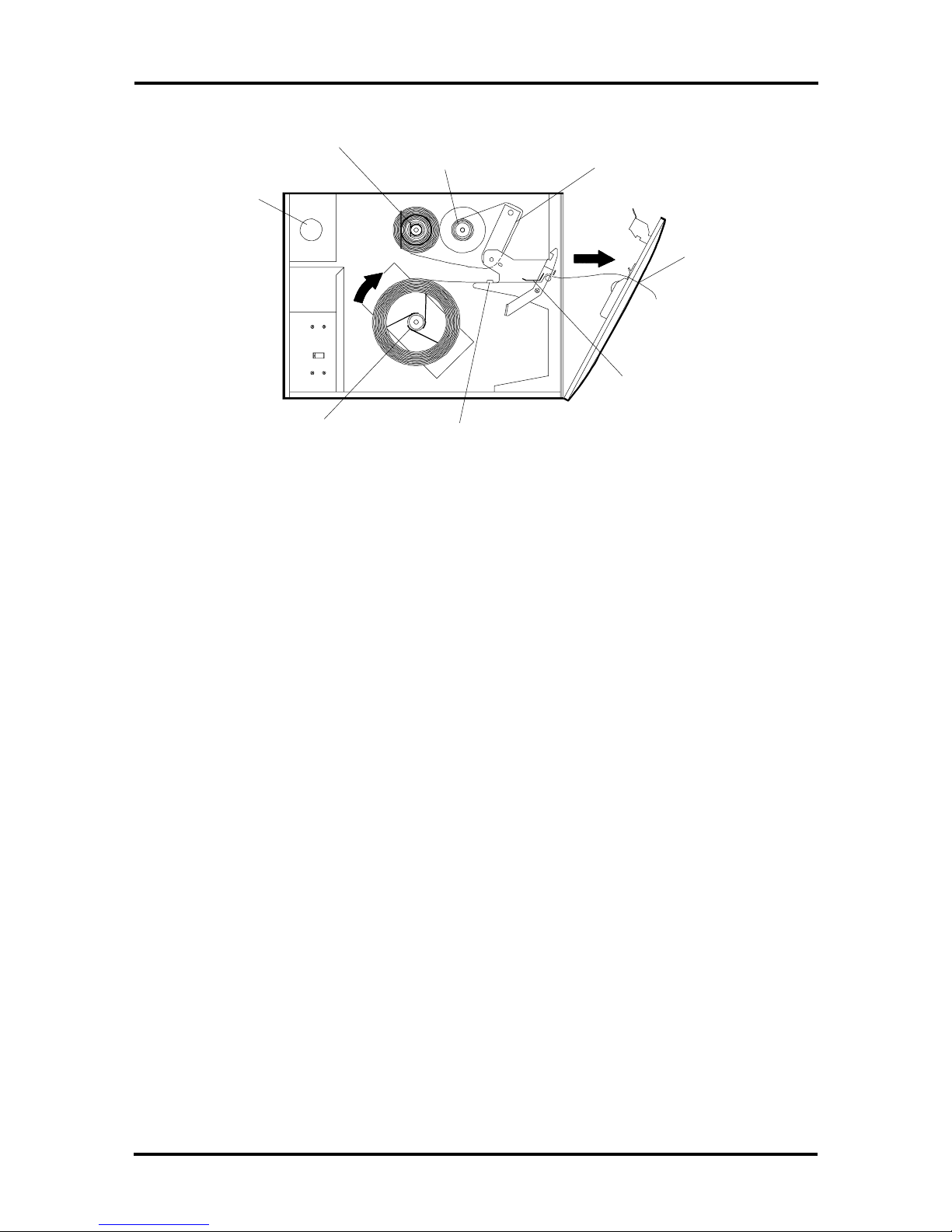
4. Open the front panel and print head.
5. Rero ute the label strip downward past the peel-off ro ller and through the label
release paper slot (see Figure 2-13).
Platen Roller
Peel-off/Tear Bar
Peel-off
Roller
Label Release
Paper Slot
Figure 2-13 Peel-Off Mode Label Routing (Model 48 and 412)
6. While gen tly pulling the liner downward, c lose and latch the prin t head assembly,
making sure the print head is securely latched. Then close and latch the front
panel.
Figure 2-14 sho ws a cut-away view of the label routing path for peel-off mode.

2-26 Setup
Peel-off/Tear Bar
Label Me dia
Label
Platen Roller
Backing
Paper
Peel-Off
Roller
Label Rel ease
Paper Slot
Figure 2-14 Model 48 and 412 Peel-Off Mode Label Routing – Cut-Away View
7. Press Online. Two labels w ill feed cons ecutively. The first label will fee d and
separate (peel) from the backing paper (liner) and exit t he label exit slot. (T he
liner exits through the label release paper slot.) After the first label feed s, manually
remove this label from the lab el exit slo t and then wait fo r th e sec ond label to
finish feeding.
When the second label has fed, the printer pauses. “PEE L OFF LABEL” appears
in the control panel LCD disp lay.
8. Remove the label from the exit s lot . When you have removed the label, the label
roll will a utomatically back up so that the next label is in posit ion for printing.
“ONLINE, READY” will appear in the control panel LCD.

Setup 2-27
Model 88
Th e following subsection desc ribes how to load labels for the Int elliBar Mo del 88. S ee
“Models 48 and 412” earlier in this section to load labels in t he Inte lliBar Mod el 48 and 412
printers.
Standard Mode, Tear-Off Mode, Cut-Off Mode (Models 88)
If the printer is operating in standard, tear-off, or cut-o ff mode, follow these steps to load
labels.
1. Open the printer’s left side cover and to p cover.
2. Place the label roll on the label supply spindle, label side up, so the roll unwinds in
the clockwise direction (see the following figure).
3. Pull up the print head release latch and raise the print head (see Figure 2-15) .
Figure 2-15 Mounting the Label Roll (Model 88)
4. Grasp t he locking rod firmly with two fingers and push the rod toward the inside
of the printer. Lift up the label senso r plate when the rod slips out of the ret aining
hole (see the following figure).

2-28 Setup
5. Carefully route the la b el bac king paper (liner) between th e metal label width
guides, under the label sensor plate, and o ver t he platen roller (see Figure 2-16).
Platen Roll
Locking Rod
Label Widt h Guides
Label Sensor Plate
Picture shown without
front bez el or covers
installed.
Figure 2-16 Installing Labels (Model 88)
6. Lower the label senso r plate and slide the locking rod toward the left side of the
printer so the rod fits into the hole and secures the sensor plate.
7. Close and securely lock the print head with the lat ch lever.

Figure 2-17 Locking the Print Head (Model 88)
Setup 2-29
8. Close t he t op cover and left side cover.
Peel-Off Mode (Model 88)
If the printer operates in peel-off mode, follow these steps t o load labels.
1. From the co nt r ol panel, select the “LABEL MENU, LABEL MEASURE,
FIXED” parameter as follows (see also “Menu Tree” later in this section).
Press the Menu button (“MAIN MENU”, “PRINT MENU” appear s in the
LCD display).
Press Next (“MAIN MENU”, “LABEL MENU” ap p ear s in the LCD display).
Press Select (“LABEL MENU”, “LABEL TYPE” appears in the LCD
display).
Press Next (“LABEL MENU”, “MEASU RE LABEL” appears in the LCD
display).
Press Select (“MEASURE LABEL”, “AUTOMATIC” appears in the LCD
display).
Press Next (“MEASURE LABEL”, “FIXED” appears in the LCD display).
Press Select (“MEASURE LABEL, “FIXED” appears with an asterisk).

2-30 Setup
This setting ensures that no more than one label advances during subsequent
power-on initialization routines, avoiding po ssible label jams at the label exit slot.
2. Fro m the cont r ol panel, select the “PRINT MENU, PRINT MODE , PEEL-OFF”
parameter as follo ws ( see also “Menu Tree” later in this sectio n).
Press the Online button (“ONLINE, RE ADY” appears in the control panel
LCD).
Press the Online butto n (OFF LINE, PAUSE appear s in the 2-line cont r ol
panel LCD display).
Press the Menu button (“MAIN MENU”, “PRINT MENU” appear s in the
LCD display).
Press Select (“PRINT MENU”, “PRINT METHOD” appears in the LCD
display.
Press Next (“PRINT MENU”, “PRINT MODE” appear s in the LCD display.
Press Select. One of the print modes other than peel off appears in the LCD
display (“STANDARD”, “TEAR OFF”, or “CUT OFF”) depending on the
print mode that you previously selected (“STANDARD” is the factory
default) .
Press Next until “PEEL OFF” appears.
Press Select (“PRINT MODE , “PEEL OFF” appears with an asterisk).
3. Load labels as described in steps 1 through 5 in the previous subsection.
4. Thread approximately two feet of media through the print head to the front of the
printer.
5. Lower the label sensor plate and slide t he locking rod towar d the left side of the
printer so the rod fits into the hole and secures the sensor plate.
6. Close and securely lock t he print head with the lat ch lever.
7. Lift up the peel-of roller latch rod and rout e the label media around the back of
the peel-off roller and out the front of t he printer (see Figure 2-18). Make sure
the media exits the printer under the peel off ro ller and above the media exit
guide plate.
8. Firmly push the peel off roller latch rod down to engage the peel-off roller.

Setup 2-31
Peel-off Roller
Latch Rod (Up
Position)
Latch Rod
(Down Position)
Figure 2-18 Model 88 Peel-Off Mode Label Routing – Cut-Away View
9. Press Online. Two labels will fee d consecutively. The first label will feed and
separate (peel) from the backing paper (liner) and exit t he label exit slot. (T he
liner exits through the label release paper slot . ) After the first label feeds,
manually remove this label from the label ex it slot a nd then wait for the second
label to finish feeding.
When the second label has fed, the printer pauses. “PEE L OFF LABEL” appears
in the control panel LCD disp lay.
10. Remove the label from the e x it slot. When you have removed the label, the label
roll will a utomatically back up so that the next label is in posit ion for printing.
“ONLINE, READY” will appear in the control panel LCD.

2-32 Setup
Installing the Thermal Ribbon
Th e pr inter comes with a start-up thermal ribbon roll th at is approx imate ly 50 meters lo ng.
An unopened ribbon roll package has a shelf life of about 2 1/2 years.
NOTE:
Open ribbon ro ll wrappers carefully to
prevent the ribbo n material from ripping.
For best results, s tore ribbons in an environment that meets the following conditio ns .
Temperature: 4° F to 86° F (-20° C to 30° C)
Humidity: 20 to 80% ( non-condensing)
Model 48 or 412
To install a ribbon in the Model 48 or 412 printer, proceed as follows. If you ar e installing a
rib bon in the Model 88, see “Model 88” later in this sect ion.
NOTE:
In telliTech Int ernational I nc.
recommends that you use a ribbon that is the
same width or slightly wider than the label liner
(backing paper) to protect the print head from
unnecessary wear.
1.
Open the printer’s left side cover. Open the front panel by pressing the front panel
release lat ch (see Figure 2-19).
2.
Remove the ribbon and take-up spool from the shipping bag.
NOTE:
The take-up spool is mount ed inside t he
ribbon s pool. Grasp both ends of the ribbon
spool and gently pull them apart to separate the
take-up spool from the ribbon ro ll.
3.
Holding t he black plastic flange away from yo u, align and slide the ribbon roll
onto the supply spindle so the ribbon unwinds in the counterclockwise direct ion
from the bottom of the spool.
4.
Holding t he black plastic flange away from yo u, align and slide the take-up spool
onto the take-up spindle, being careful to align the notches.

Setup 2-33
Line up notch
Mount ribbon
roll.
Take-up
spool
Ribbon
to mount
take-up spool.
Pull blue handle
to open front
panel .
Figure 2-19 M ounting the Ribbon Supply and Take-up Spools (Model 48 and 412)
5. Open the print head assembly b y pulling up the print hea d latch lev er. Raise the
print head and gently thread the ribbon over the white teflon guides and under t he
print head (see Figure 2-20).
NOTE:
Be careful to remove any wrinkles o r
creases while threading ribbon under the print
head.

2-34 Setup
Raise print head.
Pull through
about 12" to 18"
of ribbon.
Thread ribbon
under print head.
Pull up blue
print head
release latch.
Figure 2-20 Threading the Ribbon (Model 48 and 412)
6. Guide the ribbon over the ribbon guide plate and then back t oward the take-up
spool (see Figure 2-21).
7. Attach the ribbon to the take-up spool with the adhesive patch on the ribbon
leader and turn the spool several turns in the count er clockwise direction to take
up any slack in the ribbon (see Figure 2-21).

Setup 2-35
Attach adhesive patch on ribbon leader
to take-up spool and wind spool
several t urns counterclockwise.
Guide ribbon over ribbon guide
plate.
Figure 2-21 Atta ching the Ribbon (Model 48 and 412)
8. Close and securely latch the print head (see Figure 2- 22) . Close and securely latch
the front panel. Then lo wer the left side cover.

2-36 Setup
Close front
panel and latch
securely.
Gently lower print head and
latch securely.
Figure 2-22 Securing the Print Head and Front Panel (Model 48 and 412)
Model 88
To install a ribbon the Model 88 printer, proceed as follows. If you are inst a lling a ribbon in
the Model 48 or 412, see “Model 48 or 412” earlier in this sectio n.
1. Open the printer’s left side cover and top cover.
2. Re move the ribbon and the two take-up cor e s from the shipping ba g as show n in
Figure 2-23, step A.
3. Remove the ribbo n supply and take- up spindles from the printer by lift ing the
spindles out of the mounting slots on the outside of the printer and sliding the
spindles out of the holes on the side of the printer frame (see Figure 2-24).
4. Align the key inside take-up core 1 with the slot on t he take- up spindle. Leading
with the plastic flange, slide core 1 ont o the take-up spindle (see Figure 2-23,
step B).
5. Align the key inside take-up core 2 with the key on core 1. With the plast ic flange
t railing, slide t ake-up core 2 ont o the t ake-up spind le (see Figure 2-23, ste p C).
Both co r es sho uld lock firmly in place on the take-up spindle.

Slot
Setup 2-37
Take-up Core
Take-up Core
A
Flange
B
Take-up Spindle
Take-up Core 1
Key
C
Key
Supply Spindle
Take-up Core 2
D
Removal Tape
Figure 2-23 Assembling the Ribbon Supply and Take-up Cores (Model 88)
Ribbon Leader
6. With the take-up cores in place, fit the rectangular shaft of the take-up spindle
into the rectangular hole in the side of the center printer frame (see Figure 2-24).
7. Lower the rounded shaft of the take-up spindle into the plastic mo unt ing block on
the out er pr inter frame as shown in Figure 2-24.
8. Slide the ribbon roll onto the supply ribbon spindle (see Figure 2-23, step D) and
fit the rounded end o f the supply ribbon spindle into the round hole on the side of
the center printer frame (see Figure 2-24).

2-38 Setup
9. Lo wer the rectangular shaft of the ribbon supply spindle into the metal mounting
bracket on the printer frame as shown in Figure 2-24.
Round Supply
Shaft End
Take-Up
Spindle Drive
Hole
Supply Ribbon
Spindle Holder
Rectangular
Take-Up Spindle
Shaft End
Printer Center
Frame
Supply Spindle
Rectangular Shaft
End
Metal Mounting
Bracket
Printer Outer
Frame
Take-Up Spindle
Round Shaft End
Take-up Spindle
Plastic Mounting
Block
Figure 2-24 Mounting the Ribbon Supply and Take-up Cores (Model 88)
NOTE:
When properly installed, the r ibbon
should unwind in a counterclockwise direction.
10. Open the print head assembly by pulling up the pr int head la tch lever. Raise the
print head and gently thread the ribbon under the print head (see Figure 2- 25).
NOTE:
Be careful to remove any wrinkles o r
creases while threading ribbon under the print
head.
11. Guide the ribbon over the ribbon guide plate and then back toward the take-up
spool (see Figure 2-25). Pull through at least 18 inches of ribbon. The ribbon
leader (see Figure 2-23, step D) must clear the print head.

Take-Up Spool
Setup 2-39
Ribbon Guide
Plate
Figure 2-25 Threading the Ribbon (Model 88)
12. Attach the ribbon to the take-up spool with the adhesive tape on the ribbon
leader (see Figure 2-23, step D) and turn the spool several turns in the
counterclockwise direction to take up any slack in the ribbo n (see Figure 2-26).
13. Close and securely latch the print head (see Figure 2-26). Then close the top
cover and left side panel.

2-40 Setup
Take-up Spool
Figure 2-26 Securing the Print Head (Model 88)
PRINT HEAD REMOVAL AND INSTALLATION
Th is section pr ovides proc edures for removing a print hea d from inside the IntelliBar printer
and installing a new one .
If you have a problem removing or installing th e IntelliBar print head or need answ ers to
technical questions, call 800-694-3034 (o r 978-568- 0370 for international calls).
CAUTION:
before removing or in sta lling the print head or
any ot her IntelliBar hardwa re. Voltage is pres ent
inside the printer even when t he po wer is turned
o ff. All voltage is remo ved only when th e printer
is unplugged.
Turn off and unplug the printer

Setup 2-41
Print Head Removal
To remove the print head, proceed as follows depending on the IntelliBar printer model.
NOTE:
removal procedures (except where indicated
below).
Model 48 and Model 412
To remove the print head in the Model 48 or 412 printer, pro ceed as follows. If you ar e
removin g th e print head in the Model 88 , see “Model 88” late r in t his subsectio n.
1.
Turn off and unplug the printer .
2.
Raise the left side cover and lower the front panel by pressing the front panel
release lat ch (see Figure 2-27).
To install the print head, reverse the
3.
Open the print head ass embly by pulling the print head latch lever (see Figure
2-27).
Left Side Cover
Front P anel
Release Latch
Print Head Latch Lever
Figure 2-27 Left Side Cover, Front Panel, and Print He ad Release Latches
(Model 48 and 412)

2-42 Setup
4. Loosen (completely) the two fro nt thumb screws on the print head assembly top
cover (see Figure 2-28).
5. Loosen or remove the two rear thumb screws.
6. Raise the print head assembly.
Rear
Thumb
Screws
(Loosen or
Remove)
THIN
THICKNESS AD J .
THICK
Print Head Assembly
Top Cover
NARROW
02
01
1
2
3
4
5
6
WIDE
WIDTH ADJ.
Front
Thumb
Screws
(Loosen)
Print Head Assembly
Bottom Cover
Figure 2-28 Print Head Top Cover (Model 48 and 412)
7. Pull ba ck an d re move the print head as sembly botto m cover. As shown in
Figure 2-29, free the print head from under the top cover. Figure 2-29 shows the
print head for the Model 48. The Model 412 print head contains one additional
connector descr ibed in the next step.

Model 48 Print Head
Shown
Bottom
Cover
Figure 2-29 Print Head Removal (Model 48 and 412)
Setup 2-43
8. T ur n o ver the print head and disconnect the data and power connectors (see
Figure 2-30). In addition, for the Model 412 only, disconnect the pre-heat
connector from the print head.

2-44 Setup
Print Head Data Connector Power Connector
Pre-Heat Connector
(Model 412 Only)
Print Head
Resistance and
Serial Number (see
Rev erse Side of Print
Head)
9. Remove the print head.
Model 88
Print Head
XXXX
4-Digit Resistance
Value
Figure 2-30 Print Head Cable Connectors (Model 48 and 412)
To remove the print head in t he Model 88 printer, pro ceed as follows. If you are removing
the print head in the Model 48 or Model 412, see “Model 48 and 412” earlier in t his
subsection.
1. Turn o ff and unplug the printer.
2. Open the left side cover and top cover.
3. Pull the print head latch lever ( see Figure 2-31) and raise the print head (see
Figure 2-32).
4. Loosen the two thumb screws on the front of the print head adjustment assembly
(see Figure 2-33).
Th e pr int head will drop d own out of the print head adjustment assembly.
5. Disconnect the two wiring connectors from the print head (see Figure 2-34).

Print Head Adjustment Assembly
Latch
Figure 2-31 Print Head Release Latch (Model 88)
Setup 2-45
Wiring
Print Head Adjustment
Assembly
Print Head
Figure 2-32 Print Head Adjustment Assembly (Model 88)
Figure 2-33 Print Head Thumb Scre ws (Model 88)
Thumb Screws

2-46 Setup
Wire Connectors
KJT-220-12MPL4-AT R=2028
59-00227
MADE IN JAPAN
Print Head
Figure 2-34 Print Head Connectors (Model 88)
Print Head Installation
To install a new print head after removing the old one, pro ceed as follows, depending on
yo ur I nte lliBar printer model.
Model 48 and 412
To install the print head in the Model 48 or 412 pr inter, proceed as follows. If you ar e
installing the pr int head in the Mod el 88, see “Model 88” later in t his su b section.
1.
Locate t he 4-digit resistance tag on the new print head (see Figure 2-30). Record
the resistance value.
NOTE:
serial number are located on the print head heat
sink (located on the reverse side of the print
head). This information s h ould be written dow n
for reference when adjusting the print head
voltage as described in the next section.
Both the resistance value and print head
2.
Connect the power and dat a cables to the new print head (see Figure 2-30). In
addition, fo r the Model 412 only, connect the pre-heat cable to the pre-heat
connector o n t he print head (see Figure 2-30).
3.
Align the tw o dimples in the print head top cover with the holes in the print head.
4.
Finger t ighten the two front thumb screws (see Figure 2-28) .
5.
Align the bott om cover in the top cover slot s ( see Figure 2-35), and finger tighten
the two r ear thumb screws (see Figure 2-28) .

NOTE: The four thumb screws should be
moderately tightened. Do not overtighten.
Make sure to align the bottom cover as shown
below . Misalignment of the bot tom co ver (see
detail) results in imp aired pr inter output.
Print Head Top
Cov er (Side View)
Correctly aligned
Slot
Bottom Cover
(Side View)
Misaligned
Setup 2-47
Figure 2-35 Print Head Bottom Cover Replacement – Side View
Close and securely latch the print head assembly.
6.
NOTE: After replacing the print head, see
“Print Head Voltage Adjustment” for information
about adjusting the print head voltage.
Close and securely latch the front panel.
7.
Close the left side cover.
8.
Model 88
To install the print head in the Model 88 print er , pr oceed as fo llows. If you are installing the
print head in the Model 48 or Model 412, see “Model 48 and Mo del 412” earlier in this
subsection.
Locate t he 4-digit resistance tag on the new print head (see Figure 2-36). Record
1.
the resistance value.

2-48 Setup
NOTE: Both the resistance value and print head
serial number are located on the print head heat
sink (located on the reverse side of the print
head). This information s h ould be written dow n
for reference when adjusting the print head
voltage as described in the next section.
4 Digit Number
KJT-220-12MPL4-AT R=2028
59-00227
7 Digit Number
MADE IN JAPAN
Figure 2-36 Model 88 Print Head Serial Number and Resistance Values
Connect the two print head wire connectors (see Figure 2-34).
2.
In sta ll the print head in the print head adjust ment asse mbly.
3.
Tighten the two thumb screws.
4.
Close and securely latch the print head adjust ment assembly.
5.
NOTE: After replacing the print head, see
“Print Head Voltage Adjustment” for information
about adjusting the print head voltage.
Close the top cover and left side cover.
6.
Print Head Voltage Adjustment
After you have installed t he new print head, you must set the print head vo ltage and/or ent er
the print head serial number using the following procedure and the flowcharts in Figure 237 through Figure 2-39.
Turn on the printer. When the words “ONLINE” and “INITIALIZING” appear in
1.
the LCD display, press and ho ld down the
Menu
but ton.

Setup 2-49
The words “MAINTENANCE MENU” and “DISPLAY COUNTERS” appear.
2. Pr ess the Next button once.
3. Press the Next but ton ag ain.
The words “MAINTENANCE MENU” and “HEAD VOLTAGE
ADJUSTMENT” appear in the LCD display.
4. P r ess the Select button once.
“REPLACING HEAD?” and “NO” appear.
5. P r ess the Previous button to choose “YES.”
6. Press t he Select but ton o nce.
“ENTER HEAD S/N” appears.
7. E nt e r the first two characters of the head serial number by pressing the Next
button until you get to the first two digits of the serial number.
8. Press t he Select butto n o nce t o enter the characters in print er memory.
9. Repeat the procedure in steps 6 through 8 to ent er the second half of the serial
number.
10. Press Select to enter the digits in printer memory and move you to the next
selection.
The words “ENTER HEAD OHMS” appear in the LCD display.
11. Enter the number for the print head by pressing the Previous or Next buttons
until t he co r r ect ohms value appears.
12. Press the Select button to save the setting.
The printer automatically configures the correct voltage settings for the print
head.
13. Turn off the printer to exit the Maintenance Menu.
14. Turn the printer on to resume normal operation.
The following menus show the procedur e described in steps 1 through 14 above.

2-50 Setup
MAINTENANCE MENU
PRESS SELECT
MAI NTENANCE
DISPLAY COUNTERS
MENU
THERMAL
TRANSFER
=ER
TDI SPLAY COUN
T
RRANSFE
XXXX
COUN
XXXXX
=
T
*
PRESS
NEXT TO
ADVANCE
PRESS SELECT
MAI NTENANCE
DISPLAY VOLTAGE
PRESS
NEXT TO
ADVANCE
MENU
PRESS SELECT
THERMAL
PRI NT
LOW
HIG
PREHEA
TDISPLAY COUN
DI RECT
TDISPLAY COUN =ER
ER
ADISPLAY VOLT =GE
ADISPLAY VOLT =GE
H
ADISPLAY VOLT =GE
T
=ER
DI RECT
XXXXXX
PRI NT
LOW
HIG
PREHE T
ER COUN
XXXXX
VOLT =GE
XX.
VOLT =G
H
XX.
A
XX.
COUN
XXX
XXX
X
A
Y
E
A
Y
Y
T
AVOLT =G
=
=
T
E
MAI NTENANCE
HEAD ADJVOL TAGE
* DEFAULT SETTI NG
NOTE: TO EXIT THE MAINTENANCE MENU, TURN
OFF THE PRINTER, THEN TURN IT BACK ON.
MENU
RE PL ACI NG HE
RE PL ACI NG HEAD?
Figure 2-37 Maintenance Menu Tree
N
Y
O
*
ES
AD?
(A)
SEE SETTING LOW/HIGH
HEAD VOLTAGE
(B)
SEE ENTERING PRINT
HEAD SERIAL NUMBER

Setup 2-51
ENTERING PRINT HEAD SERIAL NUMBER
FROM MAINTENANCE MENU
(B) YES
1. SERVICE PERSON PRESSES “NEXT” OR “PREVIOUS” WHICH CHANGES THE VALUE OF THE FIRST TWO POSITIONS
(0 THROUGH 9 ARE VALID FOR THE FIRST POSITION)
(0 THROUGH 9 AND XYZ ARE VALID FOR THE SECOND POSITION)
2. PRESS “SELECT” TO ENTER THE FIRST TWO ALPHA- NUMERIC VALUES
1. SERVICE PERSON PRESSES “NEXT” OR “PREVIOUS” WHICH CHANGES THE VALUE OF THE RIGHT MOST FIVE POSITIONS
(0 THROUGH 999 ARE VALID)
(0 THROUGH 99999 ARE VALID)
2. PRESS “SELECT” TO ENTER THE FIVE DIGIT NUMERIC VALUE
RNHEEET S/N
00
RNHEEET S/NAD
3Y
RNHEEET S/NAD
3Y
AD
-
0
-
0
-
6
0000
0000
3792
THE PROCESS MOVES ON TO THE ENTER HEAD OHMS DISPLAY
WHEN CORRECT SERIAL NUMBER IS IN DISPLAY, PRESS '' SELECT.
THE PROCESS MOVES ON TO THE ENTER HEAD OHMS DISPLAY
TO ABORT OR RESTART AT THE BEGINNING, PRESS “MENU”
RNHEEET OHMAD
X
X
XX
S
SEE SETTING LOW/HIGH
HEAD VOLTAGE
(A)
Figure 2-38 Print Head Serial Number Menu Tree

2-52 Setup
SETTING LOW/HIGH HEAD VOLTAGE
FROM MAINTENANCE MENU
(A) NO
SERVICE PERSON ENTERS PRINTHEAD RESISTANCE
USE "NEXT" AND "PREVIOUS" BUTTONS WITH FAST SCROLL CAPABILITY
ALLOWABLE RANGE EQUALS 1100 TO 1400
WHEN CORRECT RESISTANCE VALUE IS IN DISPLAY, PRESS "SELECT"
MAIN BOARD CALCULATES PRINTHEAD VOLTAGE AND DISPLAYS SETTING VOLTAGE VALUE TO (1) DECIMAL PLACE
VOL AG
RNHEEE
TOHMS
RNHEEET OHMS
T
AD
X
X
XX
AD
0
0
12
I
TSNTGE
E=
L
O
T
OR
W
O
XY
X.
VOL AG
T
TSNTGE
I
E=
I
HH
O
XY
T
G
X.
MAIN AREA OF BOARD SENDS NEW VOLTAGE SETTING INFORMATION TO SUB AREA OF BOARD
MAIN AREA REQUESTS VOLTAGE INFORMATION FROM SUB AREA AFTER SETTING NEW VALUE
AFTER 5 SECONDS (APPROX) DISPLAY SHOWS ACTUAL HEAD VOLTAGE
N
DIS A
DISPLAY SHOWS THE ACTUAL HEAD VOLTAGE
DISPLAY SHOWS THE SET VOLTAGE AND THE ACTUAL HEAD VOLTAGE.
ACTUAL HEAD VOLTAGE UPDATED EVERY THREE SECONDS
ACTUAL HEAD VOLTAGE UPDATED EVERY THREE SECONDS
EAMANT NI
P
C
E
O
YLL
V
NU
ME
TE
AG
Figure 2-39 Print Head Voltage Menu
NOTE: Turn off the printer to exit the
maintenance menu. Turn t he printer on to re sume
normal operation.

NOTE: The informatio n in this section is
subject to change without not ice. This
information is provided "as is" without eit her
expre ss o r implie d warranty. IntelliTech
International, Inc. disclaims any and all
warranties with regard to this information.
IntelliTech shall not be liable in any event for any
special, indirect or consequential damages o r any
damages whatsoever re sulting from loss of data,
profits or use, for any reason or in any action,
arising out of o r in connection with the use or
perfo rmance of this in formation.
Setup 2-53

Section 3
Unit Operation
The following subsections provide o per ating procedures for the printer, including
information on using the p rint er’s control pa n el menu to configur e parameter s.
Controls and Indicators
Figure 3-1 shows the co ntr ol panel for the Mo del 48 and 412 print er . Figure 3-2 shows the
contro l panel for the Mo del 88 printer. The control panel contains the LCD display, power
and alert indicators, and buttons that allow you to control and mo nitor pr inter oper ation.
Explanat ions for each butto n and indicator are listed in Table 3-1. T he subsections that
follow provide printer default set tings configured using the control panel, menu butto n
explanat ions, and contr ol panel status messages that indicate the operating condition of the
printer.
LCD Display
Power In dicator
Alert Indicator
Online Button
Feed Button
Can c el Button
Menu / Select Button
Previous/Next Button
Figure 3-1 Control Panel (Model 48 and 412)

3-2 Unit Operation
LCD Display
Status LED's
Online Button
Feed Button
Cancel Button
Select Button
Next Button
Previous Button
Menu Button
Figure 3-2 Control Panel (Mode l 88)
NOTE: With the exception of the Feed butto n,
t he control panel but to n s will not wor k unless the
printer is offline. The Feed button work s in both
o fflin e and online modes. The print er must be
o nline be fore it w ill print any dat a.
Table 3-1 Control Panel Explanations
Buttons/Indicators Explanation
Power indicator Lit whenever printer power is ON.
Aler t indicator Lit when the printer has a problem needing
attenti on, such as repl ac ing ribbons or labels.
The lam p blinks if a service related error
occurs.
Onl ine button The Online button switches the printer between
online mode when it can receive dat a and
offline mode when operation pauses so you can
change menu items or cancel an operation.
Feed button Advances labels through the print head. One
label at a time is fed each time the button i s
pushed. Wor k s i n both offline and online
modes.

Unit Operation 3-3
Table 3-1 Control Panel Explanations
Buttons/Indicators Explanation
Cancel button Performs the following funct ions:
• Quits the c ur r ent job.
• Resets the printer par ameters to the default
settings (when Cancel is pressed and held for
at least five seconds while the printer is in
offline mode).
• Clears all data in the print buf fer.
• Resets printer engi ne er r or s.
• Cancels the alar m sound.
• Cancels the pre-heat ing sequence for the
Model 412 when “OPEN PRI NT HEAD”
appears in the control panel LCD.
• Cancels the “LABEL SENSOR ADJ”
parameter setting when the control panel
LCD displays “SET LABEL, NOT GAP,
UNDER HEAD”.
Menu/Select button Used when the printer is i n offline mode.
Pressing the button t o the right selects the
menu it em and category displayed on the LCD.
Pressing the button t o the left enters the menu
listings.
Previous/Next button Moves you forward and backwards through the
menu categories and selec tions.
Display Al lows you to monitor the current state of printer
by prov iding a two-line screen f or messages.
Messages include
• operator messages requiring you to per-
form a task such as replacing the label
supply or ribbon so the printer can resume
printi ng.
• status messages that let you know the
printer’s current condition. The standard
status message reads “READY”, meaning
the printer is online and ready for use.
• error messages that let you k now when the
printer has a probl em that needs service.
• menu selections for printer configuration.

3-4 Unit Operation
Self-Test
Follow the printer self-test procedure in this subsection to verify that the printer is set up
correctly. The three self-tests exercise all the print head elements so you can also verify that
the print head is adjusted cor r ectly.
Be fore run ning the self-t est , load t he label and ribbon rolls (see “Installing the Thermal
Ribbon” and “ Installing Labels” in Section 2). Do not run the self-test without pr operly
installing a lab el and ribbon. The ribbo n and label must b e a minimum of 4.25 in. (108 mm)
wide. Running the s e lf-test with narrower ribbons or labe ls c a n damage the print hea d or
platen roller.
NOTE:
over the label and is not over the label gap. When
you turn on the printer as described below, the
label sen sor automatically detec ts the label gap.
Check that the label sensor is centered
To run t he self-test, pr oceed as fo llows.
1.
Turn on the printer an d wait for it to in itializ e.
NOTE:
At power-on, the green power and red
alert LEDs light and an audible alarm sounds.
Then “OFF LINE, INITIALIZE” appears in the
2-line, con trol pa nel LCD, followed by
“ONLINE, READY.”
The printer feeds several labels under the print head and out the label exit slot as it
automat ically measures la bel length.
2.
Press the
Online
button to take the printer offline (“OFF LINE, PAUSE” appears
in the 2 -line L CD).
3.
Press the
Menu
button to access the printer menu listings (“MAIN MENU,
PRINT MENU” appear s) .
4.
Press
Next
four times to advance to t he Co nfiguration submenu (“MAIN MENU,
CONFIGURE MENU” appears).
5.
Press
Select
to access the available selections (“TEST PAGE, BAR CODE,
FONT LIST”).

Unit Operation 3-5
TEST PAGE — Prints a preformatted test label listing the standard default
settings (see Figure 3-3) .
NOTE: TEST PAGE output includes the label
count used for determining print head life. The
label count is mea sured in linear inches.
BAR CODE — Prints a preformatted bar code label used for adjusting print
quality (see Figure 3-4).
FONT LIST — Lists the resident fonts and their assigned number.
Press
6.
PAGE, you do not ha ve to p ress
Press
7.
Press
8.
Th e pr inter will run the self-test and outpu t a label. The examples in Figures 3-3
to advance to the desired self-test selection. (If running TEST
Next
.
)
Next
Select
Select
to select the self-test.
again to start the test.
and 3-4 show the TEST P AGE and BAR CODE self-tests. To stop the test,
press the
Examine the printout carefully for signs of uneven print quality between the left
9.
Online
but ton.
and right sides of the label (or the top and bottom). Examine the top and bottom
edges of t he label to make sure the horizontal print line is straight. I n addition,
look carefully for blank areas in the label.
If print quality is uneven, not st r aight, or if blank areas appear, these are signs
that t he print head pressure, position, and/or alignment need adjustment (see
“Mechanical Adjustments” in Section 5) or t hat the ribbon is wrinkled as it
passes under the print head.
Ex amine the print sample for ov erall print quality, mak ing su re the output is crisp
10.
and sharp wit h o ptimum black and whit e contrast between text and graphics and
the label surface.
If the printed image is too light, or if the image is too dar k, u se t he control pane l
menu to adjust the print density and head voltage so that the desired print
quality is obtained (see “Menu Tree” in the next subsectio n).

3-6 Unit Operation
Test Page
Figure 3-3 Self-Test Sample Printout (All Models)

Unit Operation 3-7
Bar Code
Figure 3-4 Bar Code Sample Printout (All Models)
Menu Tree
You can control the o p er ation o f the printer through soft war e commands from the host
co mputer or through the printer’s co ntrol panel menu butt on. Info rmation on softw a re
commands is provided in t he Pr ogrammer’s Reference Guide. To configure t he printer t o
meet unique job requirements, use t he co ntr ol panel menu tree described below to select
new default parameters.
The menu consists of parameter listings with a variety of setting selections. These listings
contro l printer features and configurations. For nearly all printing jobs, the default fact ory
settings do not ha ve to be changed.
Default Fac tory Settings
Table 3-2 lists the default printer settings.

3-8 Unit Operation
Table 3-2 IntelliBar Default Printer Settings
Main Menu Print er Def ault
PRINT MENU
Print method
Print mode
Ribbon type
Print speed
LABEL MENU
Label type
Measure label
Set label length*
Set gap length*
ADJUSTMENTS MENU
Print density
Print position
Cut position
Label sensor adj**
LJIII SETUP MENU
Font source
Font number
Point size
Symbol set
Number of copies
Page rotati on
Line spacing
Top/bottom margin
Thermal transfer
Standard
Express wax
4, 8, or 12 in. per second (ips) maximum
(depending on model)
Die cut
Automatic
—
—
0
0
0
—
Internal
6 (Courier 10)
xx
Roman-8
Copies=1
0
1/48
Ignore
CONFIGURATION MENU
Test print
Hex dump
Page protect
Panel language
Interface
MAINTENANCE MENU***
Display counter s
Display head voltage
Adj head voltage
*Does not appear when “Measure Label” i s set.
**Sensor adjusts automatically to liner opacity.
*** Not availabl e from main menu. Accessed by turning the printer off and then on again. When “Initialize”
appears in the LCD display, push and hold down the Menu button until “Mai nt enance Menu” appears in
the LCD display.
Test page
Off
Yes
English
Parallel
xxxx
xx.xxxx
xxxx

Unit Operation 3-9
Changing Settings
To configure the print er to meet unique job requirements, refer to the detailed menu t r ee in
Figure 3-5. Change t he printer’s default settings from the control panel as follows.
1. Turn the printer ON.
2. Press
Online
t o t ake the printer offline. The 2- line dis play will read “OFF LIN E,
PAUSE.”
Menu
Press
Press
Press
. The 2-line display will change to “MAIN MENU, PRINT MENU.”
Prev
to go to the previous item in the menu structure.
Next
to go to the next item in the menu structur e.
Select
to choose the displayed setting.
NOTE:
Once the selections have been made,
3. Press
press Online to exit the menu, save the
selections, and put the print er online (“READY”
appears in the display). The selectio ns are not
lost when you turn the printer off.
You can restore the factory default set ting with the following steps.
1. Press
Online
t o t ake the printer offline. The 2- line dis play will read “OFF LIN E,
PAUSE.”
2. Press and hold do wn
Th e pr in ter parameter s will reset to th eir factory default sett ings excep t fo r:
Page protect
Panel language
Interface
Unit o f measure
Select
for at least 5 seconds.

3-10 Unit Operation
MAIN MENU
MAI N MENU
MAI N MENU
LABEL
MAI N MENU
MAI N MENU
JUTSPL3
MAI N MENU
N
MAI N MENU
UCO F I G R
MENUPR I NT
SELECT TO PRINT MENU
NEXT
TO LABEL MENU
MENU
TO ADJUSTMENTS MENU
MENUAENDJUSTM TS
TO LASERJET 3 SETUP MENU
MENUE
TO CONFIGURATION MENU
EMENU
MENUPRINT
NOT AVAILABLE FROM MAIN MENU. ACCESSED AT POWER-ON. HOLD
DOWN MENU BUTTON WHEN “INITIALIZE” APPEARS ON L CD DISPLAY
ACCESSED AT POWER-ON WHILE HOLDING DOWN MENU SWITCH
NOT AVAILABLE FROM MAIN MENU
MENUMAINTENANCE
TNERSDISPLAY COU
TO MAINTENANCE MENU
Figure 3-5 Menu Tree

PRINT MENU
PRI NT
PRI NT
MENU
METHOD
PRESS SELECT
PRI NT
TRANSFER
METHOD
Unit Operation 3-11
=
*
PRESS
NEXT TO
ADVANCE
PRI NT
MENU
PRI NT
PRESS
NEXT TO
ADVANCE
PRI NT
RIBBON TYPE
MENU
PRESS
NEXT TO
ADVANCE
PRI NT
PRI NT
MENU
SPEED
PRESS SELECT
MODE
PRI NT
RIBBON TYPE
EXP
RIBBON TYPE
RIBBON TYPE
DURA RES I N
RIBBON TYPE
RU
RIBBON TYPE
DURA
METHOD
DIRECT
RESS
DURA
WAX
GGED
PRESS SELECT
=
=
*
WAX
=
WAX
=
=
RES IN
=
PLUSNRES I
PRI NT=M
PRI NT=M
PRI NT=M
PRI NT=M
PRI NT
PRI NT
STANDARD
PEE L
TEAR
CUT
X
XX
ODE
ODE
OFF
ODE
OFF
ODE
OFF
SPEED
.
0
SPEED
IPS
6
IPS
*
=
=
* DEFAULT SETTING
Figure 3-5 Menu Tree (cont’d)
PRI NT
SPEED
2
1
IPS
=

3-12 Unit Operation
LABEL MENU
LABEL
MENU
LABEL TYPE
PRESS SELECT
LABEL TYPE
DIE CUT
=
*
PRESS
NEXT TO
ADVANCE
LABEL TYPE
CONT I N OUUS
=
PRESS SELECT
URMAEELABELS=
O
AEDUT MA
URMAEELABELS=
FRI
T
X
MAE
PRESS
NEXT TO
UPR
MENULABEL
LABELS
E
ADVANCE
URMAEELABELS=
O
R
AE
TPLO
ONLY AVAILABLE WHEN CONTINUOUS OR OPERATOR PANEL IS SELECTED
ET
ETS
MENULABEL
LABEL G H
ETSNTLE G H
/
N
ES
TL
6016
=
INCHES
OR
ETSNTLE G H
MENULABEL
P
A
NET TLES
GHG
521mm
PANET TLESGHG
/
216
=
INCHES
OR
PANET TLESGHG
* DEFAULT SETTING.
3mm
*
C
AINE
*
=
=
Figure 3-5 Menu Tree (cont’d)

ADJUSTMENTS MENU
Unit Operation 3-13
PRESS SELECT
ADJUSTMENTS
PRINT DENSI TY
PRESS
NEXT TO
ADVANCE
PRESS SELECT
ADJUSTMENTS
PRINT
POS I T I ON
PRESS
NEXT TO
ADVANCE
PRESS SELECT
MENU
MENU
PRINT DENSI TY
PRINT DENSI TY
PRINT DENSI TY
PRINT
PRINT
PRINT
CUT
-
1
5
*
0
+
1
5
POS I T I ON
-
03
POS I T I ON
*
0
POS I T I ON
+
03
POS I T I ON
-
03
=
=
=
=
=
=
=
ADJUSTMENTS
CUT
POS I T I ON
PRESS
NEXT TO
ADVANCE
MENU
CUT
CUT
POS I T I ON
0
POS I T I ON
+
=
*
=
03
PRESS SELECT
ADJUSTMENTS
LABEL NSE SOR JAD DER HEA
MENU
SET P PEA,NOT
GAP , UN
R
D
ADJUST
PLEASE WAI T
ING
THIS MESSAGE LASTS FOR
APPROXIMATELY 5 SECONDS
AND THEN RETURNS TO THE
* DEFAULT SETTING.
ADJUSTMENTS MENU
Figure 3-5 Menu Tree (cont’d)

3-14 Unit Operation
LJ3 SETUP MENU
O
*
48
NT
=
=
*
=
*8/48
=
*
=
=
=
=
FONT
LINE I
FONT
COUR IER
FONT
COUR IER
FONT
COUR IER
FONT
COUR IER
FONT
COUR IER
FONT
COUR I ER 12 B LDO
FONT
U
NIVERS DBLO
MODELS 48 AND 412 HAVE 7 ADDITIONAL
OUTLINE FONTS.
PAGE
PAGE
PAGE
PAGE
FONT SOURCE
EJUTSPL3
FONT
P
OINT SIZE
POINT SIZE CAN ONLY BE SELECTED WHEN AN OUTLINE FONT HAS BEEN SELECTED.
SYMBOL SET
NUMBER
PAGE ROTAT I ON
LINE
MENUEJUTSPL3
MENU
NUMBER
MENUEJUTSPL3
MENUEJUTSPL3
MENUEJUTSPL3
OF COP I ES
MENUEJUTSPL3
MENUEJUTSPL3
SPACING
FONT SOURCE
FONT SOURCE
SOFT FONT CAN ONLY BE SELECTED WHEN
A SOFT FONT HAS BEEN DOWNLOADED.
POINT S I ZE
SYMBOL SET
SYMBOL SET
#OFCOPIES=
#OFCOPIES=
#OFCOPIES=
LINE
LINE
LINE
INTERNAL
SOFTF
XX
ROMAN - 8
XXXXXXX
X
1
XXXX
9999
SPACING
1/48
SPACING
SPACING
48
/
NB
MU
P
R
NB
MU
NB
MU
NB
MU
NB
MU
NB
MU
NB
MU
NB
MU
RA
O
T
0
RA
O
T
RA
O
T
RA
O
T
=
ER O
TER
N
=
ER
0
1
=
ER
10
ITAL
=
ER
1
0
BOLD
=
ER
12
=
ER
1
2
ITAL
=
ER
=
ER
ON
I
T
*
I
ON
T
09
I
ON
T
081
I
ON
T
072
16
6
*
12
18
24
30
36
42
=
=
=
=
LJ3 USET P MENU
TOP BOT M RGIN/A
* DEFAULT SETTING
TOP/BOT MARGIN=
IG ORE*N
TOP/BOT MARGIN=
AC EPTC
Figure 3-5 Menu Tree (cont’d)

CONFIGURATION MENU
PRESS SELECT
CONF I GURE
TEST PRINT
MENU
TEST PRINT
TEST
=
PAGE
Unit Operation 3-15
*
PRESS
NEXT TO
ADVANCE
CONF I GURE
CONF I GURE
CONF I GURE
PAN LANGUAGE
HEX DUMP
PAG PROTECT
E
LE
PRESS
NEXT TO
ADVANCE
MENU
MENU
MENU
TEST PRINT
TEST PRINT
HEX DUMP
HEX DUMP
BAR
NT
F
O
ENGLISH
GERMAN
FRENCH
SPAN I SH
CODE
LIST
=
OFF *
=
ON
=
=
PAGE PROTECT
PAGE PROTECT
=PANEL L ANGUAGE
*
=PANEL L ANGUAGE
=PANEL L ANGUAGE
=PANEL L ANGUAGE
UNI T OF MEASURE
UNI T OF MEASURE
NO
*YS
E
INCHES
MT C
*
IER
=
=
CONF I GURE
* DEFAULT SETTING
INTERFACE
MENU
ITALIAN
IETNRFACE EMNU
INTERFACE
INTERFACE
INTERFACE
TOTHSROP
PARAL LEL *
RS-232-C
-
RS
MENU
MENU
MENU
422A
=PANEL L ANGUAGE
*
=
=
=
Figure 3-5 Menu Tree (cont’d)
SERIAL
SUBMENU

3-16 Unit Operation
SERIAL SUBMENU
3S-2CR-
2
BAU RATED
2SC-3R-
2
ABIT
DAT
PRESS
NEXT TO
ADVANCE
PRESS SELECT
3S-22CR-
FLOW C NTR
3S-22CR-
RBUSTXON
O
OOL
PRESS SELECT
S
DATA BITS=
8*
DATA BITS
FLOW CONT
FOWCONTROL
L
RBUSTXON
RBUSTXON
7
X
ON X OF F
DRT
R
D
S
O
NO*
O
FOF
OL =
*
=
R
BAUD
BAUD
BAUD
BAUD
BAUD
BAUD
BAUD
BAUD
RE
TA
=
*9600
RE
TA
19200
RE
38
RE
RE
RE
RE
RE
=
TA
=
400
TA
=
3
00
TA
=
6
00
TA
=
00
21
TA
=
2400
TA
=
4800
3S-22CR-
DTR
* DEFAULT SETTING
POLARI
3S-22CR-
PARI TY
TY
DR
DR
PRITY=
PRITY=
PRITY=
POLARI TY
H
ITGH
POLARI TY
L
OTW
N
OANE
O
DAD
E
VAEN
=
*
=
*
Figure 3-5 Menu Tree (cont’d)

MAINTENANCE MENU
PRESS SELECT
MAI NTENANCE
DISPLAY COUNTERS
MENU
THERMAL
Unit Operation 3-17
TDISPLAY COUN
T
RRANSFE
XXXX
TRANSFER
=ER
COUN
XXXXX
=
T
*
PRESS
NEXT TO
ADVANCE
PRESS SELECT
MAI NTENANCE
DISPLAY VOLTAGE
MENU
PRESS
NEXT TO
ADVANCE
PRESS SELECT
MAI NTENANCE
HEAD ADJVOLTAGE
* DEFAULT SETTI NG
NOTE: TO EXIT THE MAINTENANCE MENU, TURN
OFF THE PRINTER, THEN TURN IT BACK ON.
MENU
THERMAL
PRINT
LOW
HIG
PREHEA
RE PL ACING H E
RE PL ACING H EAD?
N
Y
O
ES
*
TDISPLAY COUN
DIRECT
TDISPLAY COUN =ER
ER
ADISPLAY VOLT =GE
ADISPLAY VOLT =GE
H
ADISPLAY VOLT =GE
T
AD?
=ER
DIRECT
XXXXXX
PRINT
LOW
HIG
PREHE T
SEE SETTING LOW/HIGH
HEAD VOLTAGE
SEE ENTERING PRINT
HEAD SERIAL NUMBER
ER COUN
XXXXX
VOLT =GE
XX.
VOLT =G
H
XX.
A
XX.
COUN
XXX
XXX
X
A
Y
A
Y
Y
=
T
=
T
E
E
AVOLT =G
(A)
(B)
Figure 3-5 Menu Tree (cont’d)

3-18 Unit Operation
SETTING LOW/HIGH HEAD VOLTAGE
FROM MAINTENANCE MENU
(A) NO
SERVICE PERSON ENTERS PRINTHEAD RESISTANCE
USE "NEXT" AND "PREVIOUS" BUTTONS WITH FAST SCROLL CAPABILITY
ALLOWABLE RANGE EQUALS 1100 TO 1400
WHEN CORRECT RESISTANCE VALUE IS IN DISPLAY, PRESS "SELECT"
MAIN BOARD CALCULATES PRINTHEAD VOLTAGE AND DISPLAYS SETTING VOLTAGE VALUE TO (1) DECIMAL PLACE
VOL AG
RNHEEE
TOHMS
RNHEEET OHMS
T
AD
X
X
XX
AD
0
0
12
I
TSNTGE
E=
L
O
T
OR
W
O
XY
X.
VOL AG
T
TSNTGE
E=
I
I
HH
O
XY
T
G
X.
MAIN AREA OF BOARD SENDS NEW VOLTAGE SETTING INFORMATION TO SUB AREA OF BOARD
MAIN AREA REQUESTS VOLTAGE INFORMATION FROM SUB AREA AFTER SETTING NEW VALUE
AFTER 5 SECONDS (APPROX) DISPLAY SHOWS ACTUAL HEAD VOLTAGE
N
DIS A
DISPLAY SHOWS THE ACTUAL HEAD VOLTAGE
DISPLAY SHOWS THE SET VOLTAGE AND THE ACTUAL HEAD VOLTAGE.
ACTUAL HEAD VOLTAGE UPDATED EVERY THREE SECONDS
ACTUAL HEAD VOLTAGE UPDATED EVERY THREE SECONDS
EAMANT NI
P
C
E
O
YLL
V
NU
ME
TE
AG
Figure 3-5 Menu Tree (cont’d)

Unit Operation 3-19
ENTERING PRINT HEAD SERIAL NUMBER
FROM MAINTENANCE MENU
(B) YES
1. SERVICE PERSON PRESSES “NEXT” OR “PREVIOUS” WHICH CHANGES THE VALUE OF THE FIRST TWO POSITIONS
(0 THROUGH 9 ARE VALID FOR THE FIRST POSITION)
(0 THROUGH 9 AND XYZ ARE VALID FOR THE SECOND POSITION)
2. PRESS “SELECT” TO ENTER THE FIRST TWO ALPHA- NUMERIC VALUES
1. SERVICE PERSON PRESSES “NEXT” OR “PREVIOUS” WHICH CHANGES THE VALUE OF THE RIGHT MOST FIVE POSITIONS
(0 THROUGH 999 ARE VALID)
(0 THROUGH 99999 ARE VALID)
2. PRESS “SELECT” TO ENTER THE FIVE DIGIT NUMERIC VALUE
RNHEEET S/N
00
RNHEEET S/NAD
3Y
RNHEEET S/NAD
3Y
-
0
-
0
-
6
AD
0000
0000
3792
THE PROCESS MOVES ON TO THE ENTER HEAD OHMS DISPLAY
WHEN CORRECT SERIAL NUMBER IS IN DISPLAY, PRESS '' SELECT.
THE PROCESS MOVES ON TO THE ENTER HEAD OHMS DISPLAY
TO ABORT OR RESTART AT THE BEGINNING, PRESS “MENU”
RNHEEET OHMAD
X
X
XX
S
SEE SETTING LOW/HIGH
HEAD VOLTAGE
(A)
Figure 3-5 Menu Tree (cont’d)

3-20 Unit Operation
Controlling the Prin ter
Table 3-3 explains the settings and functions of menu choices.
Table 3-3 Controlling the Printer
Menu Selection Description
Print Menu
PRINT METHOD
Transfer
Direct
PRINT MODE
Standard
Peel of f
Tear off
Selects thermal transfer printing and enables
the ribbon sensor. Thermal transfer printing
requires less print head ener gy and therefore
increases print head life.
Selects dir ec t thermal printing (no ribbon
required). Disables the ribbon sensor and
automatically increases print head energy.
Higher energy requirements and direct cont ac t
between the print head and label surface
shortens print head life.
Printing is continuous. Normal ly selected when
using either t he internal or exter nal rewinder or
when printing l ong str ips of labels.
Use for printing one label at a time while
automatically separating t he label from t he liner
(backing paper).
Use for printing one label at a time and
positioni ng for easy tear-off.
Cut off
RIBBON TYPE Use to match ribbon type with label appl ication.
PRINT SPEED Use to match t he pr int speed wi th the
NOTE: Peel-off, Tear-off, and Cut-off modes feature automatic backup prior to print i ng the next label so
that printing begins at t he beginning of t he label.
When the optional Label Cutt er is installed,
allows automat ic cut-after- pr int of die cut labels.
Intended f or c utting backing paper.
Not all r ibbons perform equally at the same
print speed and print densi ty settings. By
selecting t he c or r ec t ribbon for the appl ication,
the printer automatically adjusts the print speed
and print densit y to predetermined average
values.
applicat ion. The type of ribbon and label media
(along with the level of print quality desi r ed) ar e
also critical factors when choosing the cor r ec t
print speed.

Table 3-3 Controlling the Pri n ter (cont’d)
Menu Selection Description
Unit Operation 3-21
Label Menu
LABEL TYPE
Die cut
Continuous
MEASURE LABEL
Automatic
Fixed
Operator panel
Use to select die-c ut labels and enable the
printer’s label sensor, whic h detects the
beginning of a label. Die-cut labels must have a
minimum label gap of 0.125 in. (3 mm).
Use to select continuous media (labels with no
gaps) and disable the label sensor. Requires
setting of label and gap length (see “Operator
Panel” below).
Automat ically measures die-c ut label length at
power on by advancing a predetermined
number of blank labels.
Disables automatic label measurement. The
last label length measured during automatic
measuring i s stored in memory, and this value
is used at power on. Use this feat ur e when the
label media remains constant (no change in
size).
Select t his feature to print on c ontinuous labels
or die-cut labels that are less than 0.95 in. ( 24
mm) long. You must set label length and gap
length. Minimum l abel length is 0.51 in. (13
mm) and minimum gap length is 0.125 in.
(3 mm).
Set label length
Set gap length
Used to enter label length information when
continuous media is selected or operator panel
is selected. Lengt h c an be set in increments of
1/16 in (1.6 mm).
Used to enter gap length information when
continuous media is selected or operator panel
is selected. Lengt h c an be set in increments of
1/16 in (1.6 mm).

3-22 Unit Operation
Table 3-3 Controlling the Pri n ter (cont’d)
Menu Selection Description
Adjustment Menu
PRINT DENSITY Used to increase or decrease pri nt head
PRINT POSITION Used to establish the first print line r elative to
temperat ur e r esul ting in darker or lighter print.
Allowable range is +15 to -15. Increasing the
number by pressing the NE XT button causes
the printed ar eas to get darker; decreasing the
number by pressing PREV IOUS causes the
printed areas to get lighter.
the leading edge of the label. Adjustable range
is 0.12 in. ( 3 mm) forward or backward i n 0.004
in. (0.1 mm) steps. Increasing the number by
pressing the NEXT button moves the first line of
print back on the label; decreasing the number
by pressing PREVIOUS moves the first print
line closer t o the front edge of t he label.
For details, see “Print Position Adjustment” in
Section 4.
CUT POSITION Adjusts the cut or tear position when advanci ng
labels using tear- off and cut-off print m odes.
For tear-off mode, use this adj ustment to
ensure that the label perforations or the c enter
of the label gap is directly above the edge of
the tear bar. For cut-off mode, use this
adjustment to ensure t hat cutting occurs in the
center of the label gap. All owable r ange is +30
to -30. Adj ustable range is 0.12 in. (3 m m)
forward or backward in 0.004 in. (0.1 mm)
steps. Increasing the number by pressing the
NEXT button causes the cut position to move
forward; decreasi ng the number by pressing
PREVIOUS moves the positi on bac k ward.
LABEL SENSOR ADJ Automatically calibrates sensitiv ity of label
sensor to the opaqueness level of the label and
liner.

Table 3-3 Controlling the Printer (cont’d)
Menu Selection Description
Unit Operation 3-23
LJIII Setup
FONT SO URCE
Internal
Soft font
FONT NUMBER Used to select the ty pe face. Ever y font
POINT SIZE
SYMBOL SET
NUMBER OF COPIES
PAGE ROTATION
Selects the printer’s internal resident fonts.
Selects the downloaded (soft) fonts as defaul t
fonts. Not sel ec table if soft font is not loaded.
(resident or sof t) is assi gned a font number that
is used to select a specific type fac e. See TEST
PRINT below for information on printing out a
font list, which lists the resident fonts and their
numbers.
Used to select a specific size for outline font s.
One point equals 1/72 in. Not selectable i f
selected f ont is not an outline font.
Used to select a specific character set for
international use.
Used to print from 1 to 9999 copies of the same
label.
Used to rotate the contents of the label in four
different orientations:
0 = portrait
90 = landscape
180 = reverse portrait
270 = reverse landscape
LINE SPACING
TOP/BOTTOM MARGIN
Ignore
Accept
Used to set the l ine spacing in 1/48 in.
increments.
Activates an additional 35 scan lines of print
area on each of t he top and bottom page
margins compared to standard PCL. The result
is an unprintable area of 15 scan lines top and
bottom ( 1/20-in). 1 scan line equal s 1/300 in.
Accepts standard PCL unpri ntable page
margins of 50 scan lines top and bottom.
 Loading...