


Installation and Operation User Guide
Marine Satellite Communication Antenna System
v60


Serial number of the product
This serial number will be required for the all troubleshooting or service inquiries.
© 2010 Intellian Technologies Inc. All rights reserved. Intellian and the Intellian
logo are trademarks of Intellian Technologies, Inc., registered in the U.S. and
other countries. The v-Series and the v60 is trademarks of Intellian Technologies,
Inc. Intellian may have patents, patent applications, trademarks, copyrights,
or other intellectual property rights covering subject matter in this document.
Except as expressly provided in any written license agreement from Intellian,
the furnishing of this document does not give you any license to these patents,
trademarks, copyrights, or other intellectual property.
All other logos, trademarks, and registered trademarks are the property of their
respective owners. Information in this document is subject to change without
notice.
Every effort has been made to ensure that the information in this manual is
accurate. Intellian is not responsible for printing or clerical errors.
Intellian Technologies Inc.
348-5 Chungho-Ri Jinwi-Myeon
Pyeongtaek-Si, Gyeonggi-Do
451-862 Korea
Tel +82 31 379 1000
Fax +82 31 377 6185
Email info@intelliantech.com
March, 2011
Intellian Technologies USA, Inc.
9004 Research Drive
Irvine, CA 92618, USA
Tel +1 949 727 4498
Fax +1 949 271 4183
Email info@intelliantech.com
Doc. No. MV60-110308

INDEX

5
INDEX
CERTIFICATIONS
6
INTRODUCTION
Introduction to Intellian v60 9
Features of Intellian v60 10
System Configurations 11
INSTALLING THE ANTENNA
System Package 13
Planning the Installation 18
Antenna Installation 21
INSTALLING THE ACU
Mounting the ACU 33
Ship Gyro Connection 35
OPERATING THE ACU
Introduction 39
Normal Mode 40
Setup Mode 43
Installation Settings 44
Antenna Settings 46
Satellite Settings 57
System Settings 64
PC CONTROLLER SOFTWARE
Introduction 73
PC to ACU Communication Setup 74
Main Menu 76
Controller Menus 78
REMOTE WEB ACCESS
Introduction 85
Main Page 86
Antenna Settings 88
Antenna / ACU Firmware Upgrade 100
Ethernet to Serial Settings 104
WARRANTY
112
TECHNICAL SPECIFICATION
113

Doc Number IT10-DC1020-01
Intellian Technologies, Inc.
EMEA & APAC Headquarters
2F Dongik Bldg., 98 Nonhyun-dong
Kangnam-gu, Seoul 135-080, Korea
Tel: +82 2 511 2244
Intellian Technologies USA, Inc.
US Headquarters
9261 Irvine Blvd.
Irvine, CA 92618 USA
Tel: +1 949 916 4411
R&TTE Declaration of Conformity (DoC)
We, Intellian Technologies, Inc. located at 2F Dongik Bldg., 98 Nonhyun-dong, Kangnam-gu, Seoul 135-080, Korea
declare under our sole responsibility that the product(s) described in the below to which this declaration relates is in
conformity with the essential requirements and other relevant requirements of the Radio and Telecommunication
s
Terminal Equipment(R&TTE) Directive (1999/5/EC).
Product Information:
Product Name(s):
Intellian v60, 60cm Ku-band Maritime VSAT Antenna System
Intellian v110, 105cm Ku-band Maritime VSAT Antenna System
Intellian v130, 125cm Ku-band Maritime VSAT Antenna System
Model Number(s):
V1-60-XXX, V1-110-XXX, V1-130-XXX
To provide the presumption of conformity in accordance to Annex III(encompassing Annex II) of Directive 1999/5/EC;
the following harmonized standards and normative documents are those to which the product’s conformance is
declared, and by specific reference to the essential requirements of Article 3 of the Directive 1999/5/EC.
wardhtiWfoetaDlluFnideilppA)s(dradnatSelcitrACE/5/5991
SAFETY (Art 3.1.a) IEC EN 60950-1: 2001 (1
st
decnerefeRtoN)noitidE
EMC (Art. 3.1.b)
IEC EN 60945: 2002
ETSI EN 301 489-1 V1.8.1: 2008
Not Referenced
SPECTRUM (Art. 3.2)
ETSI EN 301 428 V1.3.1: 2006-02
ETSI EN 302 340 V1.1.1: 2006-04
Not Referenced
Supplementary Information:
Notified Body Involved:
(Testing Organization)
Nemko USA, Inc.
11696 Sorrento Valley Rd. Suite F San Diego, CA 92121-1024, USA
ERI EMC Research Institute
66-6, Jeil-RI, Yangji-Myun, Cheoin-Gu, Yongin-Si, Gyeonggi-Do, Korea
Technical/Compliance
File Held by:
Intellian Technologies, Inc. (R&D Department)
32-1-4 Block, Jinwi Industrial Park Jinwi-Myeon, Pyeongtaek-Si, Gyeonggi-Do, Korea
Place and Date of issue:
Seoul, Korea on 20 Oct 2010
Authority: Steve Cha
/ Director, R&D
Signature:
Date:
20 Oct, 2010
CERTIFICATIONS

Doc Number IT10-DC0801-01
Intellian Technologies, Inc.
EMEA & APAC Headquarters
2F Dongik Bldg., 98 Nonhyun-dong
Kangnam-gu, Seoul 135-080, Korea
Tel: +82 2 511 2244
Intellian Technologies, Inc.
US Headquarters
9261 Irvine Blvd.
Irvine, CA 92618 USA
Tel: +1 949 916 4411
FCC Declaration of Conformity
Intellian Technologies, manufactures of stabilized maritime VSAT antenna systems for satellite communication at sea,
supplies stabilized maritime VSAT antenna systems to the satellite communication service provide
rs for their ESV
(Earth Station on Vessels) networks.
FCC §25.222 defines the provisions for blanket licensing of ESV antennas operation in the Ku-band. It defines the
antennas radiation, and each article regulates the followings;
§25.222 (a)(1)(i)(A): Regulation for Azimuth Direction & Co Polarization
§25.222 (a)(2)(i)(B): Regulation for Other Direction & Co Polarization
§25.222 (a)(1)(i)(C): Regulation for Cross Polarization
Intellian Technologies, Inc. declares that the below
identified products comply with the threshold level as defined in
§25.222(a)(1)(i)(A):, and declares that the products are in accordance with all defined regulations from
§25.222(a)(1)(i)(B) to §25.222(a)(1)(i)(C) at the below stated input power spectral density, with an N value of 1.
Product description
EIRP spectral density limit
Intellian v60, 60cm Ku-band maritime VSAT antenna system
-22.3 dBW/ 4KHz
Intellian v110, 105cm Ku-band maritime VSAT antenna system
-16.2 dBW/ 4KHz
Intellian v130, 125cm Ku-band maritime VSAT antenna system
-14.0 dBW/ 4KHz
Intellian Technologies, Inc. declares that the above antennas will maintain a pointing error of less than or equal to 0.2
degree under specified ship motion conditions in accordance with the requirements of §25.222 (a)(1)(ii).
Intellian Technologies, Inc. declares that the above antennas will automatically cease the transmission within 100 mute
command to the modem within 100 milliseconds if the target satellite and the axis of the main lobe of the ESV antenna
ex
ceeds 0.5 degree and will not resume until such angle is less than or equal to 0.2 degree in accordance with the
requirements of §25.222 (a)(1)(iii)
Radiation pattern data is available upon request to verify the conformance.
Authority: Steve Cha Signature:
/ Director, R&D
Date: Aug 01, 2010

v60 – Marine Satellite Communication System
8
Introduction to Intellian v60
Features of Intellian v60
System Configurations
INTRODUCTION

9
INTRODUCTION
Introduction to Intellian v60
The Intellian v60 is a 60-centimeter (23.6-inch) Ku-band, three-axis stabilized VSAT
antenna system capable of receiving SCPC, MCPC, TDMA or Spread Spectrum
transmissions. Designed for ocean vessels in the recreational, commercial or oil
and gas market segments, as well as military vessels, the v60 offers "always on"
high-quality broadband communications, in even the roughest weather and sea
conditions.
The v60 provides seamless, uninterrupted broadband connectivity for worldwide
on-demand communications, is compatible with a comprehensive list of service
providers and ensures professional mariners and yacht owners reliable, unlimited
connectivity at sea.
The v60 offers a wide minus 10-degrees to plus 100-degrees elevation range and
unlimited azimuth, eliminating cable wrap and the lengthy loss of signal connection
as the system unwinds. It is ideal for mission critical operations, such as surveillance
or vessel monitoring, that require uninterrupted connectivity, or in Voice over Internet
Protocol (VOIP) communication and information downloads where signal loss is
unacceptable.
An open platform, the v60 is compatible with any modem and supports 4-,
6- and 8-Watt BUCs, providing owners the flexibility to choose the service and
communications speeds that is right for their needs. The new antenna embraces
Intellian's design philosophy that simplicity equals reliability.
The unit is designed to making it easier for owners, operators and installers to add
new features when updating firmware, and even offers a "roll back" function that
resets the firmware to a previous version. The v60 offers seamless remote monitoring
and control and a power switch on the ACU's front panel for your convenience.

v60 – Marine Satellite Communication System
10
Features of Intellian v60
Enjoy always-on broadband connection at sea
Intellian v60 is the most modern communication system that offers a high-speed and
always-on broadband connection at sea, where the atmospheric and environmental
conditions are very harsh.
Best solution for all kinds of vessels
The v60 is the best solution for all kinds of vessels that require the satellite
broadband connection around the globe. The major RF components are designed
and manufactured by Intellian’s solid in-house engineering to achieve superior
antenna gain and xpol isolation recognized among the best performances in the
industry.
Gyro-free satellite search capability
Intellian’s new generation Gyro-fee satellite search function enables the v60 to
acquire and lock onto the satellite without requiring a separate input from the ship’s
gyrocompass
Wide elevation range
The v60 has a wide elevation range from -10° to 100°, respectively which offer
seamless signal reception while the vessel is traveling near the Equator or Polar
Regions.
Remote management solution
The v60 can be accessed, monitored, and controlled from any location in the world
through the embedded web server, which can save tremendous time and cost from
the hundreds of routine maintenance activities. These solutions include operating
firmware upgrade, tracking parameters resets and system diagnostic.
Save installation and maintenance time
Simple design allows users to install and setup the system without the need for a
skilled engineer. The v60 provides the utmost in reliability resulting in time and cost
savings in maintenance.
Various platform compatibility
The v60 is fully integrated with ABS(Automatic Beam Switching) function with
leading service providers who use the embedded OpenAMIP protocol of the
iDirect platform and v60 is also compatible with various platforms such as Hughes,
Comtech, SatLink and more.

11
INTRODUCTION
System Configurations
For your satellite communication system to work properly, the system will have to
be connected with all of the provided components properly, as shown in the figure
below. Separate purchase of a satellite modem, ship’s gyrocompass, Intellian Dual
VSAT Mediator are required.
Basic System
Configuration
MODEM Interface
Gyro-Compass Input
RS-232/RS-422
Antenna Rx
24 V == 5 A
BUC
Power
Modem Rx
MODEM Interface
Gyro-Compass Input
RS-232/RS-422
Antenna Rx
24 V == 5 A
BUC
Power
Modem Rx
MODEM Interface
Gyro-Compass Input
RS-232/RS-422
Antenna Rx
24 V == 5 A
BUC
Power
Modem Rx
ANT1
RS232 & RS422 ACU1 ACU2 PC InterfaceConsole
ANT2 MODEM NMEA
Heading
+ -
RX MODEM Interface ACU Interface
ANT1 ANT2 MODEM
TX
Satellite Modem
(Not supplied)
Antenna Control Unit
Modem InterfaceModem RX
Antenna TX
Antenna RX
BUC
Power
BUC
Power
BUC
Power
AC 100 ~ 240V
(50~60Hz)
Ship’s Gyrocompass
(Not supplied)
RX1 TX1 TX2
Antenna
Unit 1
Antenna
Unit 2
RX2
AC 100 ~ 240V (50~60Hz)
Antenna Control Unit 1
Satellite Modem
Antenna Control Unit 2
Mediator
Ship’s
Gyrocompass
TX RX Interface
PC
Dual System
Configuration

v60 – Marine Satellite Communication System
12
INSTALLING THE ANTENNA
System Package
Antenna Unit
ACU (Antenna Control Unit)
Installation Kit
Planning the Installation
Selection of Antenna Installation Site
Configure Radiation Hazard/Blockage Zones
System Cables
Power Requirement
Tools Required for Installation
Installation
Unpacking the Wooden Crate
Antenna Dimensions
Antenna Mounting Templates
Position the Radome
Open the Radome Hatch
Mount the Radome
RF Cable Connections
Secure the RF Cables

13
INSTALLING THE ANTENNA
System Package
The package of Intellian v60 consists of antenna unit, ACU and installation kit box.
Antenna unit
ACU
Installation kit box

v60 – Marine Satellite Communication System
14
Antenna Unit
The antenna unit includes an antenna pedestal inside a radome assembly unit. The
pedestal consists of a satellite antenna main dish with RF components mounted
on a stabilized pedestal. The radome protects the antenna pedestal assembly unit
from the severe marine environment.
Antenna Unit

15
INSTALLING THE ANTENNA
ACU (Antenna Control Unit)
ACU provides power to the antenna and BUC (Block Up Converter). The digital
VFD (Vacuum Fluorescent Display) allows for easy operation of the ACU, even in
the dark.
The functions of the ACU are as follows,
• System startup
• Setting the satellite
• Editing satellite information
• Setting the antenna parameter
• Setting the antenna manual search
• Setting the LNB local frequency
• Setting radiation hazard or blockage zone
• Setting modem connections
• Setting GPS and Gyrocompass
• Display versions
• Display power status
• Performing diagnostic tests
• Backup and restore the system settings
• Set up the interface with a PC
Antenna Control Unit
Front panel
Rear panel

v60 – Marine Satellite Communication System
16
Installation Kit
Contains the items required for securing the antenna unit and ACU to the vessel.
Antenna Q’ty Description Size Remark
x5
Hex. Bolt M8 x 50L
Antenna-Deck
x5
Flat Washer M8
x5
Spring Washer M8
x5
Hex Head Wrench
Bolt
M6 x 30L
Radome
(Spare Blots)
x5
Dome Washer M6
ACU Q’ty Description Size Remark
x5
Tapping Screw ø 4 x 16
Table Mount
Bracket
x10
Flat Head Screw M3 x 8L
Rack Mount
Bracket ACU
x5
Sem's Bolt M3 x 12L
Table Mount
Bracket ACU

17
INSTALLING THE ANTENNA
Other Components
Item Image Q’ty Description Size Remark
1
x2
ACU
Bracket
Rack - ACU - 19 inch Rack
x2
Table - ACU-Table
2
x1
RG6 Cable 3 m
ACU(Modem Rx)
to Modem
3
x2
RG6 Cable 15 m
Antenna(Modem Tx) to
Modem & Antenna(ACU
Rx) to ACU(Antenna Rx)
4
x1
BUC Power Cable 15 m
Antenna(BUC In) to
ACU(BUC Power)
5
x1
AC Power Cord
(CEE7/7)
1.5 m ACU Power
6
x1
AC Power Cord
(USA)
1.8 m ACU Power
7
x1
PC Serial Cable 1.8 m ACU to PC
8
x1
USB Cable
(A-A / M-M)
1.8 m ACU to PC
9
x1
iDirect Interface Cable 1.5 m ACU to Modem
10
x2
D-Sub 9 Pin Male
Connector
- ACU
11
x1
BUC Power Connector
(AK950-2)
- Antenna (BUC In)
12
x1
N to F Adapter -
N(Male) to F(Female)
Adapter
13
x1
Installation CD - -
14
x1
User Manual - -
15
x1
Mounting Template - -
16
x1
Unpack Wooden Crate
Instruction Guide
- -

v60 – Marine Satellite Communication System
18
Planning the Installation
Selection of Antenna Installation Site
Install the antenna in accordance with the following procedures to insure maximum
performance of the antenna. The ideal antenna site has a clear view of the horizon
or satellite all around. Please be sure there are no obstacles within 15º above the
center of the antenna. Any obstacles can prevent the antenna from transmitting and
receiving the satellite signal.
Do not install the antenna near by the radar especially on the same plane as their
energy levels may overload the antenna front-end circuits. It is recommended to
position the antenna at least 4 feet (1.2 m) above or below the level of the radar and
minimum of 15 feet (4.6 m) away from the high power short wave radars.
The mounting platform should be rigid enough and not subjected to excessive
vibration. The movement of the antenna can be minimized by installing at the
center of the vessel. If these conditions can be only partially satisfied, find the best
compromised installation site between the various considerations.
Elevation Limit
of Obstacles
15°
Configure Radiation Hazard/Blockage Zones
It is important to setup the radiation hazard or blockage zones for Intellian VSAT
communication systems. The ACU can be programmed with relative azimuth and
elevation sectors to create up to five zones where transmit power would endanger
personnel who are frequently in that area or blockage exists. Several things happen
when the antenna is within one of these zones.
1. “BLOCK” will be displayed on the ACU screen.
2. Tracking continues as long as the signal level is greater than the predefined
threshold value. When the signal level drops below the threshold value the
antenna will wait “Search Wait Time” parameter amount of time and re-target the
satellite you targeted last. The antenna will continue to re-target the satellite until
the satellite is re-acquired and tracking can be resumed.
3. A transmit inhibit output from the ACU will disable/mute the modem transmit.
Antenna Unit Obstacle

19
INSTALLING THE ANTENNA
System Cables
Before installing the system cables, you need to take the following points into
consideration.
1. All cables need to be well clamped and protected from physical damage and
exposure to heat and humility.
2. Cable with an acute bend is not allowed.
3. Where a cable passes through an exposed bulkhead or deck head, a watertight
gland or swan neck tube should be used.
• RF Cable (Customer Furnished)
Due to the voltage losses across the length of the RF coaxes at L-Band, Intellian
recommends the following 50 ohm coax cable types for standard system installations.
For cable runs longer than 120 meters, please consult Intellian Technologies.
Intellian provides a N to F type adapter to connect 75 ohm coaxial cables.
Run Length Coaxial Cable Type
Up to 30 meters LMR-300-50
Up to 70 meters LMR-400-50
Up to 120 meters LMR-600-50
Recommended
RF Cables
Power Requirement
Intellian v60 has been designed to work on a vessel’s power supply rated at 100240 V AC.
• BUC Power Cable
Cable Length mm2 per conductor
Up to 30 meters 1.25 mm
2
Up to 50 meters 2.30 mm
2
Up to 70 meters 3.00 mm
2
Up to 120 meters 5.00 mm
2
Recommended
BUC Power Cables
Type Multi-conductor, Shielded
Number of wires 5 conductors for Synchro
2 conductors for NMEA
• Gyro Compass / GPS Interface Cable (Customer Furnished)
Recommended
RF Cables

v60 – Marine Satellite Communication System
20
Tools Required for Installation
Power Drill
Cross-Head Screwdriver
Minus-Head Screwdriver
8 mm Spanner
11 mm Spanner
13 mm Spanner
4 mm Allen key 5 mm Allen key

21
INSTALLING THE ANTENNA
Antenna Installation
Unpacking the wooden crate of v60
Step 1.
Remove the top panel and 8 pins from the hinges of the wooden crate.

v60 – Marine Satellite Communication System
22
Step 2.
Remove ACU box and installation kit box.

23
INSTALLING THE ANTENNA
Step 3.
Remove 4 shipping blots that mount the antenna to the pallet.

v60 – Marine Satellite Communication System
24
Step 4.
Open the top radome and remove the shipping restraints
( bracket mounted to the antenna pedestal and tie wrap fixed the azimuth axis).
M6 Dome Washer
M6 Hex Wrench Bolt

25
INSTALLING THE ANTENNA

v60 – Marine Satellite Communication System
26
Antenna Dimensions
The method of installation and mounting of antenna may vary with vessel design
but the following procedures are applicable in most situations, and will result in a
secure and effective installation. Confirm the height and diameter of the antenna
before installing it.
Radome Dimensions
78.0 cm (30.7")
84.5 cm (33.3")

27
INSTALLING THE ANTENNA
Ø 45.8 cm (18”)
Radome Bottom
1 cm( 0.4") Holes
30.4 cm (12")
45.8 cm (18")
45.8 cm (18")
30.4 cm (12")
Antenna Mounting Templates
The mounting holes must be in the exact same place as shown in the diagram
below.
BOW direction

v60 – Marine Satellite Communication System
28
Installing the System Cables
The cables must be routed from the antenna through the deck and through various
ship spaces to the antenna control unit. When pulling the cables in place, avoid
sharp bends, kinking, and the use of excessive force.
Cable Entry
Cable Entry Base of Radome
Mounting the Radome
Bolt the radome base directly to the ship’s deck or mounting plate (flat mounting
area).
Mounting the Radome
Antenna Unit
Deck
M8 Flat Washer
M8 Spring Washer
M8 Hex Bolt
13mm Spanner

29
INSTALLING THE ANTENNA
RF Cable Connections
Ensure that the power switch is off during the installation period and all the cables
are connected properly between the antenna control unit and the power switch
box. Using tie wraps supplied with radome, secure the RF cables connected to the
power switch box. When all the hardware and cable have been installed, turn on
the power switch.
Modem Tx Cable
(From Modem)
ACU Rx Cable
(From ACU)
On/ Off Switch
BUC Power Cable
(From ACU)
Antenna Power Cable
(From Antenna)
Rotary #2 Rx Cable
(From Antenna)
BUC Power Cable
(From Antenna)
Rotary #1 Tx Cable
(From Antenna)
Power Switch Box

v60 – Marine Satellite Communication System
30
M6 Dome Washer
M6 Hex Wrench Bolt
WARNING: The elevation and cross-level motor breaks prevent dish damage while the
antenna is in power off mode. However, Intellian strongly recommends to restraint the
antenna pedestal properly during underway conditions when power is removed from
the antenna. The normal operating condition for the v60 is to remain powered up at all
times.
Reinstall the top radome.

31
INSTALLING THE ANTENNA
Position the Radome
The radome should be positioned with the BOW marker aligned as close as possible
to the ship’s centerline.
Recommended size of the
support pedestal
100~150 cm (40~60”)
Base Panel
0.8 cm (0.3”)
Suppor ting Pole
Appr Ø10 cm (3.9”)

INSTALLING THE ACU
Mounting the ACU
19” Rack Mount Type
Table Mount Type
ACU Dimensions
Selection of ACU Installation Site
Connecting the System
Connecting the System with a Ship’s Gyro
Connecting the System without a Ship’s Gyro
ACU Connector Guide

33
INSTALLING THE ACU
Mounting the ACU
Intellian supplies two type of mounting methods (a) 19” Rack Mount Type and (b)
Table Mount Type to mount your ACU.
19” Rack Mount Type
- The ACU should be installed using the two supplied Rack Mounting Brackets
which allow for a side 19” rack mounting configuration.
- Using the self tapping screws supplied, attach the mounting brackets to the sides
of the ACU.
- Place the ACU in the location where it is going to be installed.
- Connect the cables to the rear of the ACU.
Table Mount Type
- The ACU should be installed using the two supplied Table Mounting Brackets
which allow for a top or bottom mounting configuration.
- Using the self tapping screws supplied, attach the mounting brackets to the sides
of the ACU.
- Place the ACU in the location where it is going to be installed.
- Using a pencil to mark the 4 hole positions (2 each side), and use the appropriate
drill bit to drill them.
- Connect the cables to the rear of the ACU.
WARNING: Ensure that the cables connected to the ACU are long enough to prevent
damage themselves when the ACU is pulled out from the rack.
19" Rack Mount Type
Table Mount Type

v60 – Marine Satellite Communication System
34
Selection of ACU Installation Site
The ACU should be installed below deck, in a location that is:
Dry, cool, and ventilated.
The front panel should be easy accessible to user.
POWER
Antenna Control Unit
Power
M
R
1 2 3
4 5 6 0
7 8 9
F
TRACKING
ERROR
DNPC
OK
3.2 cm (1.3")
46.5 cm (18.3")
48.5 cm (19.1")
13 cm (5.1")
20 cm (7.9")
43.1 cm (17")
45.4 cm (17.8")
47.4 cm (18.6")
4.4 cm (1.7")
38.1 cm (15")
ACU Dimensions
Dimension of ACU

35
INSTALLING THE ACU
Ship Gyro Connection
Connecting the System with a Ship’s Gyro
The ship’s gyrocompass provides true heading input to the antenna which easily
allows the antenna to target and acquire the desired satellite. Therefore, Intellian
always recommend the user to connect a ship’s gyro to the antenna through the
gyro interface on the ACU. If the ship’s gyrocompass output is other than NMEA
0183 and Synchro separate purchase of a gyro converter is required.
• NMEA 0183 Gyro Compass Interface Cable (Customer Furnished)
• Type: 2 conductors for NMEA 0183
• NMEA heading sentence: xx HDT (4800 Baud, 8, N,1)
If there is no HDT sentence then use HDM sentence instead.
WARNING: Determine the type of gyrocompass OUTPUT on the ship, assure that the
GYRO TYPE parameter is set correctly (refer to the operation section of this menu).
Heading in most cases will be 000.0 and you will have to enter the initial value of ships
current value whenever you turn on the ACU. The ship’s heading is not required to
input when your system is connected to NMEA or 1:1 synchro gyrocompass output.
Ship’s Gyro Connection
Strip the cable for 5 mm (0.2")
Do not solder the cable

v60 – Marine Satellite Communication System
36
Connecting the System without a Ship’s Gyro
For a vessel where the ship’s gyro compass is not installed or is difficult to be
connected, the Intellian Gyro-Free satellite search function will be automatically
enabled to allow the antenna to lock onto the desired satellite without requiring an
external heading input.
The table below provides an example of the Gyro-Free satellite search algorithm.
The Search 1 or Search 3 satellite search pattern will be triggered according to the
existence of heading input and the setting of the heading device.
Search 1: The antenna will search for the target satellite by turning its azimuth
angle in CCW direction until the antenna receives the lock signal from the
modem or the DVB transponder of the target satellite is decoded by the
antenna.
Search 3: The antenna will search for the target satellite by turning its azimuth angle
directly to the position calculated using the ship’s heading input and lock
onto the satellite.
Quick Setup Procedure
• Set the satellite having DVB transponder as the target satellite.
• Set “No Device” to the heading device.
• The antenna will search for the target satellite by turning its azimuth angle in CCW
direction and lock onto the satellite signal until the antenna receives a lock signal
from the modem or the DVB transponder of the target satellite is decoded.
• Set the heading device as NMEA / Synchro
• Enter “Manual search” menu and press “Function” key to save the current settings.
Intellian ACU will automatically calculate and save the BOW offset.
• Upload the real TARGET satellite pre-configured from the library.
Setting of Heading Device
Existence of Heading Data No Device NMEA/Synchro Ground Test
w/ Heading Data
Search 1 Search 3 Search 3
w/out Heading Data
Search 1 Search 1 Search 3

37
INSTALLING THE ACU
ACU Connector Guide
• Console Port
NOTE: NMEA GPS IN/OUT Sentence: GPGLL (4800 Baud, 8, N, 1)
12345
6789
54321
9876
Pin Signal Pin Signal
1
GND
6
GPS OUT -
2
GPS OUT +
7
MODEM_SIGNAL_IN
3
MODEM_LOCK
8
MODEM_CTRL2
4
MODEM_CTRL1 (TX MUTE)
9
GPS IN -
5
GPS IN +
ACU Console Port
D-Sub 9 pin Female
D-Sub 9 pin Male connector
Supplied Component
12345
6789
54321
9876
12345
6789
12345
6789
Pin Signal Pin Signal
1
-
6
-
2
-
7
-
3
SYNCHRO_R2
8
SYNCHRO_R1
4
SYNCHRO_R3
9
SYNCHRO_S2
5
SYNCHRO_S1
Pin Signal Pin Signal
1
-
6
-
2
RXD
7
-
3
TXD
8
-
4
-
9
-
5
GND
Pin Signal Pin Signal
1
-
6
-
2
RXD +
7
RXD -
3
TXD +
8
TXD -
4
-
9
-
5
GND
ACU Synchro Port
D-Sub 9 pin Female
D-Sub 9 pin RS232
Connector
D-Sub 9 pin Male connector
Supplied Component
D-Sub 9 pin RS422
Connector
• Synchro Connector
• RS232 / 422 Connector (Modem & BUC Interface)

OPERATING THE ACUOPERATING THE ACU
Introduction
Normal Mode
Setup Mode
Installation Settings
Antenna Settings
Manual Search
Setup Antenna LNB pol Angle
Search Parameters
Setup Antenna Parameters
Setup Block Zone
Antenna Diagnostic Test
Satellite Settings
Load Satellite
Edit Satellite Information
Add Satellite Information
Check NID
System Settings
Set LNB Local Oscillator Frequency
Set Location
Set Modem Port
System Backup & Restore
Display Versions

39
OPERATING THE ACU
This section of the handbook describes how to setup your system after installing
the ACU. It includes the following functions:
Introduction
ACU Soft Keys
Soft key Function
MODE
Enter SETUP mode
RETURN
In SETUP mode: return to previous menu / option or save the
adjusted settings.
In normal mode: return to the first page of antenna current status.
FUNCTION
Save the adjusted settings.
ARROW KEYS
Select from the alternative options to increse or decrese the
selected character to the desired value.
OK
Enter next step / menu
NUMBER KEYS
Input the numbers
Soft Key Functions
PC Cable
(USB)
Status
LED
Return Function Number
Keys
Power
Switch
Mode Arrow Keys

v60 – Marine Satellite Communication System
40
INTE LLI A N TECH N OLO G IES IN C .
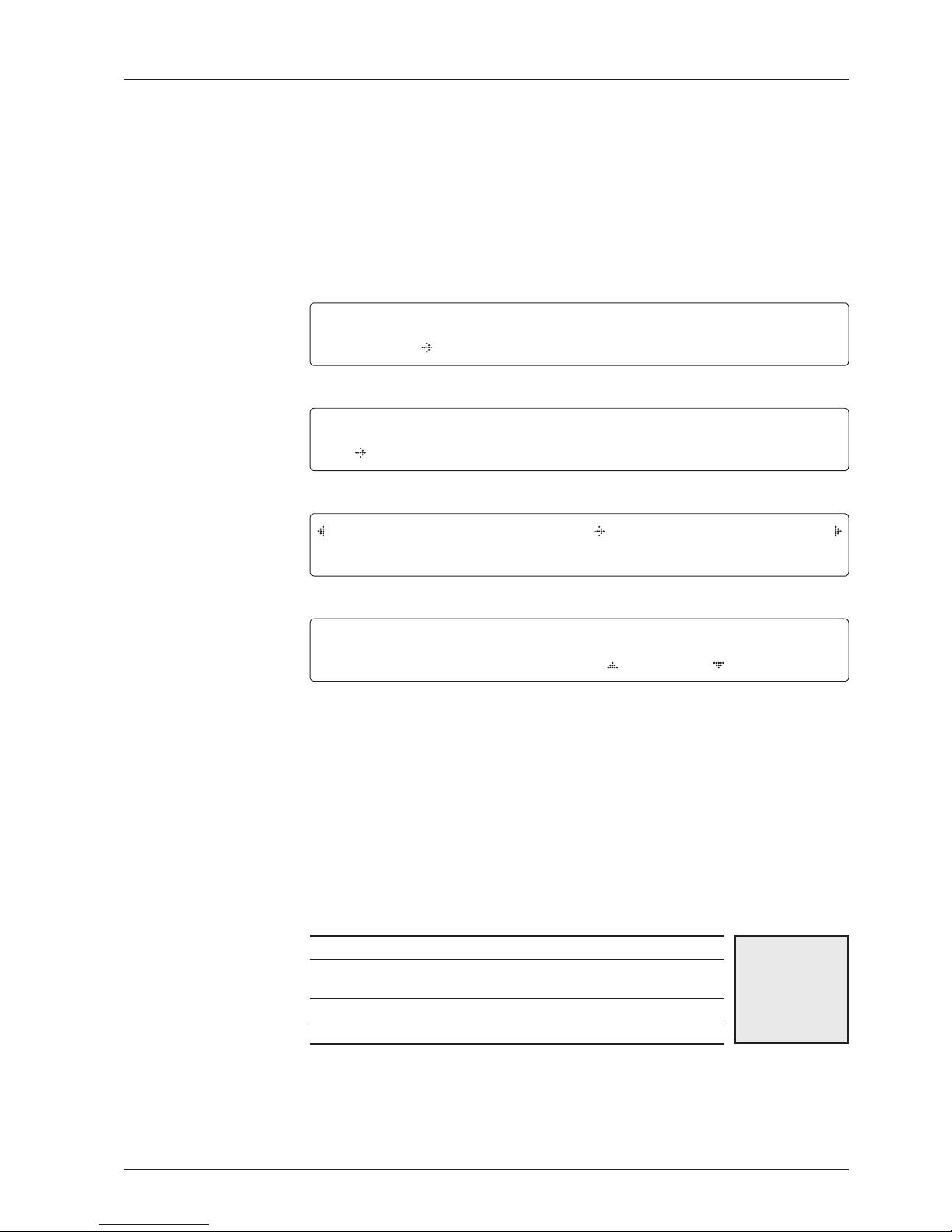
1. The data communication is being established between the antenna and the ACU.
IN I TIA L IZE - ANT E NNA I N FO
IN T ELL I AN V60
2. The ACU receives antenna information.
IN I TIA L IZE - EL POS I TIO N
IN T ELL I AN V60
3. The elevation angle and cross level angle are initialized.
IN I TIA L IZE - AZI M UTH PO S ITI O N
IN T ELL I AN V60
4. The azimuth angle is initialized.
IN I TIA L IZE - SAT POS ITI O N
IN T ELL I AN V60
5. The antenna returns to the target satellite position.
SE A RCH 1 138. 0 E TELS T_1 8 SI G:3 0 1 VL
AZ :29 2 .7( 20 2.7) EL: 48. 3 SK:- 7 2.0
6. The antenna is searching for the target satellite.
TR A CKI N G 138. 0 E TELS T_18 SI G:5 0 1 VL
AZ :29 2 .7( 20 2.7) EL: 48. 3 SK:- 7 2.0 Fn
7. The antenna has locked onto the satellite.
Startup
With the system installed and power applied, the ACU screen will show the following
sequence.
Normal Mode
Start up
Initialize antenna info
Initialize elevation &
cross level angle
Initialize azimuth angle
Initialize target satellite
position
Search status
Tracking status

41
OPERATING THE ACU
SE A RCH 1 138. 0 E TELS T_1 8 SI G:3 0 1 VL
AZ :29 2 .7( 20 2.7) EL: 48 .3 SK: -72 . 0
1. The antenna is searching for the target satellite.
TR A CKI N G 138. 0 E TELS T_18 SI G:3 0 1 VL
AZ :29 2 .7( 20 2.7) EL: 48 .3 SK: -72 . 0 Fn
2. The antenna has locked onto the target satellite.
Current IF signal level (SIG / AGC) is displayed. SIG will be displayed when NBD (Narrow band
detection) mode for TRACKING SIGNAL is chosen to be used and AGC will be displayed
when DVB mode of TRACKING SIGNAL is chosen to be used.
The symbol “•” will be only displayed when the satellite signal is strong enough to locked
onto. [VL] indicates the LNB's local frequency corresponding to 13V is in use for the signal
reception.
VL: 13V + 0 kHz
HL: 18V + 0 kHz
VH: 13V + 22 kHz
HH: 18V + 22 kHz
True azimuth [292.7] position of the antenna is the sum of ships heading 090.0 [HDG] and
antenna relative [202.7].
SAV E CU RRE N T SAT INF O ?
YE S NO
3. Press FUNCTION key to save current satellite information or abort and return to the main
display. "Fn" will be displayed only if the antenna is in tracking mode.
TR A CKI N G 138. 0 E TELS T_18 SI G:3 0 1 VL
AZ :29 2 .7( 20 2.7) EL: 48 .3 SK :-7 2.0 Fn
4. Press RIGHT arrow key to display NBD, GPS and ship’s heading information.
Monitoring Antenna Current Status
When the ACU power is on, it displays the status of the antenna. The current status
of the antenna is displayed as shown below.
Current search status
Current tracking status
Current tracking status
Save current satellite info

v60 – Marine Satellite Communication System
42
Tracking & Heading
information
Power status
Antenna & ACU
versions
NB D F :12 4 700 0 B W:1 0 00 S IG: 301
00 4.5 3 E 52 . 22N H D G:0 9 0.0 L: 1 000 0 Fn
5. NBD, GPS and ship’s heading information are shown.
- NBD (Narrow Band Detection) IF tracking frequency: 1247000 kHz
- Detected Band Width: 1000 kHz
- SIG (Signal Level ): 301 (When NBD mode for tracking signal is chosen)
- W (West ) / E (East) Longitude: 4.53º E
- N (North) / S (South) Latitude: 52.22º N
- HDG (Ship’s Heading): 90º
- LNB local oscillator (LO) frequency: 10000 MHz
[P W R] ANT : 26 .4V LN B: 13V + 0KH Z
ACU : 27 .1V [P OL] TX :V RX : H
6. Press RIGHT arrow key to display the current operation voltage for antenna, ACU and
LNB. POL indicates the TX polarity (VERTICAL) and RX polarity (HORIZONTAL).
V1 - 60- 0 3H AN T . SERI A L 1. 0 0
VP -T1 0 0 AC U SE RIA L 1.0 0 (1. 0 0)
7. Press RIGHT arrow key to display the below information.
- Antenna part number, antenna serial number and PCU firmware version.
- ACU part number, ACU serial number, ACU firmware version and Library version.
Press RETURN Key to return to the first page of the antenna current status.

43
OPERATING THE ACU
Setup Mode
Enter the SETUP mode simply follow the instructions below.
Searching / Tracking mode
Enter password
Setup mode
Exit setup mode
TR A CKI N G 138. 0 E TELS T_18 SI G:3 0 1 VL
AZ : 292 . 7( 202 . 7) EL : 48 .3 SK: - 7 2.0 Fn
1. While the antenna is in SEARCHING / TRACKING mode, press MODE key to enter SETUP
mode.
*
indicates the key pad lock function is on (Refer to KEY LOCK menu to setup the key
pad lock function). When key pad lock function is activated press MODE key or when “Fn”
menu is activated press FUNCTION key the ENTER PASSWORD menu will be displayed.
E N TER PA S SWO R D
- - - -
2. If the key pad lock function is on, enter the password before accessing to the SETUP
mode. If the key pad lock function is off, access to the SETUP mode directly as Step 3.
SETU P MO DE ?
YE S NO
3. Press LEFT arrow key to move cursor to YES and press OK key to enter SETUP mode or
press RIGHT arrow key to move cursor to NO and press OK key to abort and return to the
main display.
EX IT SET U P MODE ?
YE S NO
4. While the antenna is in SETUP mode, press FUNCTION key as shortcut key to exit SETUP
mode.

v60 – Marine Satellite Communication System
44
Installation Settings
During the first time installation, it is required to setup the installation settings.
Installation
menu
Latitude & Longitude
Gyro type
Select satellite
Setup mode
SETU P MO DE ?
YE S NO
1. Press LEFT arrow key to move cursor to YES and press OK key to enter SETUP mode
+ANT E NNA +S ATE L LIT E
+SYS T EM
+I N STA L LAT I ON
2. Press arrow keys to move cursor to INSTALLATION menu and press OK key to enter it.
SELE C T SATE L LIT E
[1 ] TE LST _ 18 13 8.0 0 E
3. Press UP and DOWN arrow keys to select the satellite that you wish to track and press OK
key to load the selected satellite.
LA TIT U DE LO N GIT U DE
37 . 00N 12 6 .53 E
4. Set the current LATITUDE and LONGITUDE
Press LEFT and RIGHT arrow keys until the desired character is underscored (selected).
Press UP and DOWN arrow keys to increase or decrease the value. Or press NUMBER keys
to set the desired value directly. Press OK key to set the parameter.
GYR O TY PE BO W AD JUS T
NME A 00 0
5. Set the ship’s GYRO TYPE* & BOW ADJUST
A search pattern 1 or 3 will be initiated according to which Gyro Type is selected and the
existence of the gyro input. Ensure that the supported Gyro Type is set correctly. For v60, if
the ship’s gyrocompass output is Step-by-Step (SBS), separate purchase of a gyro converter
is required.
A search pattern 1 will be initiated automatically if the gyro input does not exist and the gyro
type is selected other than GROUND TEST.
The BOW ADJUST is to offset the angle difference between the antenna’s bow and the ship’s
bow (Range: 0 – 360°).
NOTE: The bow offset will not be saved automatically if Search 1 pattern is initiated. In this case, the
antenna will need to retarget the desired satellite using Search 1 every time if the antenna restarts.

45
OPERATING THE ACU
MO DEM PO R T MO D EM PRO T OCO L
RS 2 32 SE RIA L G PS
6. Set MODEM PORT* and MODEM PROTOCOL*
MODEM PORT is to select a proper data communication port on the ACU to interface with
the satellite modem.
13V + 0 K HZ 18V + 0KH Z
10 000 M HZ 1 1 300 M HZ
13V + 2 2KH Z 18V + 22K H Z
10 000 M HZ 0 975 0 MHZ
7. Set the LNB local oscillator frequency for each voltage power. (13V +0 kHz, 18V +0 kHz,
13V +22 kHz, 18V +22 kHz)
Press LEFT and RIGHT arrow keys until the desired character is underscored (selected).
Press UP and DOWN arrow keys to increase or decrease the value. Or press NUMBER keys
to set the desired value directly.
LOA D ?
YE S NO
8. Press RETURN key to load the current setting or abort and return to the main display.
LO ADI N G ...
DO NO T TURN OF F !
9. Setting is being loaded to the system.
The ACU will restart the system automatically after uploading the setting.
DO NOT TURN OFF ACU POWER while the data is being uploaded.
TR A CKI N G 138. 0 E TELS T_18 SI G:3 0 1 VL
AZ :29 2 .7( 20 2.7) EL: 48. 3 SK : -72 .0 Fn
10. Antenna has locked onto the target satellite.
MODEM PORT*
RS232
RS422
ETHERNET
Modem port & Modem
protocol
LNB local frequency
GYRO TYPE*
NO DEVICE
NMEA
SYNCHRO
GROUND TEST
Gyro search mode
Loading settings
Load
Tracking status
MODEM PROTOCOL*
I/O CONSOLE
OPEN AMIP
SERIAL GPS
Setting of Heading Device
Existence of Heading
Data
No
Device
NMEA/
Synchro
Ground
Test
w/ Heading Data
Search 1 Search 3 Search 3
w/out Heading Data
Search 1 Search 1 Search 3

v60 – Marine Satellite Communication System
46
Antenna Settings
Manual Search
Search the desired satellite manually.
Antenna movement
Setup mode
Save
Manual search menu
Antenna menu
SETU P MO DE ?
YE S NO
1. Press LEFT arrow key to move cursor to YES and press OK key to enter SETUP mode.
+ ANT E NNA +SA T ELL I TE
+SYS T EM +IN S TAL LAT I ON
2. Press OK key to enter ANTENNA menu.
+ M ANU A L SEAR CH +SET PO L A NGL E
+SEA R CH PAR A M +S E T PARA METE RS
3. Press OK key to enter MANUAL SEARCH menu.
ST E P SIZE AZ IMU T H ELE V ATI O N AGC
# 00. 2 #
23 1 .7 48.3 3 0 1 Fn
4. Current IF tracking signal level (AGC) / (SIG) is displayed to assist you in manually peaking
AZIMUTH (0°-360°) and ELEVATION (0°-90°) angle for best signal level.
Press NUMBER key to change the STEP SIZE (Range: 0.1~99.9). Press LEFT and RIGHT
arrow keys to increase or decrease the azimuth angles. Press UP and DOWN arrow keys to
increase or decrease the elevation angles.
Press FUNCTION key to save current settings or abort and return to the main display.
SAV E CURR E NT SAT IN F O?
YE S NO
5. If the current settings are able to locate the satellite, press FUNCTION key to save “current
satellite information”. This will help to reduce the satellite acquisition time after restarting
the system. Press LEFT arrow key to move cursor to YES and press the OK key to save the
settings.
NOTE: If the gyro type is not NMEA or the gyro is not connected to the ACU, the information cannot be
saved.

47
OPERATING THE ACU
Setup Antenna LNB pol Angle
LNB pol angle type
Setup mode
Set pol angle menu
Antenna menu
LNB pol angle Signal
SETU P MO DE ?
YE S NO
1. Press LEFT arrow key to move cursor to YES and press OK key to enter SETUP mode.
+ ANT E NNA +SA T ELL I TE
+SYS T EM +IN S TAL LAT I ON
2. Press OK key to enter ANTENNA menu.
+ M ANU A L SEAR CH +S ET POL A NGL E
+SEA R CH PAR A M +S E T PARA METE RS
3. Press RIGHT arrow key to move cursor to SET POL ANGLE menu and press OK key to
enter it.
SE LEC T POL A NGL E M ENU
CA L IBR A TIO N
4. Press UP and DOWN arrow keys to select the LNB pol angle menu and press OK key to
run the selected operation 'CALIBRATION' or 'MANUAL ADJUST'. Select MANUAL ADJUST
to control LNB pol angle manually. If the control board, LNB pol potentiometer or belt is
replaced, select CALIBRATION to calibrate LNB pol angle.
LNB POL A N GLE SIG N AL: 18 0
20
5. Press UP and DOWN arrow keys to increase or decrease the LNB pol angle manually and
the correspondent SIGNAL level will be displayed next to it. Press RETURN key to return to
the main display.
NOTE: LNB POL ANGLE menu will be displayed only if MANUAL ADJUST is selected.

v60 – Marine Satellite Communication System
48
Search 3 range
Search 1 range
Search Parameters
Setup mode
Manual search menu
Antenna menu
Search param
S E TUP M ODE ?
YE S N O
1. Press LEFT arrow key to move cursor to YES and press OK key to enter SETUP mode.
+AN T ENN A +S A TEL L ITE
+ S YST E M +INS T ALL ATI O N
2. Press OK key to enter ANTENNA menu.
+ M ANU A L SEAR C H + S ET POL A NGL E
+SE A RCH P ARAM +S ET PARA M ETE RS
3. Press arrow keys to move cursor to SEARCH PARAM menu and press OK key to enter it.
S E ARC H W AIT TI M E INCR E MEN T ST EP
03 0 0 .50
SEAR C H1 AZ SEAR CH1 EL
400 06
SEAR C H3 AZ SEAR CH3 EL
003 04
4. Set SEARCH 1 and 3 AZ (Azimuth) range and EL (Elevation) range. SEARCH 2 is reserved
for future use.
A search pattern 1 or 3 will be initiated according to which GYRO TYPE is selected
and the existence of the gyro input.
Search 1: a search pattern 1 will automatically be initiated when the ship’s heading
input does not exist / is failed. The antenna will go to the relative azimuth position
0º at the calculated elevation and search in the azimuth CCW direction and search
up +0.5º & down -0.5º with a total 6º(±3º) in elevation. The search cycle will repeat
until the antenna receives the lock signal from the modem or the DVB transponder
of the target satellite is decoded by the antenna. If the desired signal is found and
above the predefined detect level, the ACU will enter to Search 3. However, the
antenna will not initiate Search 3 pattern but go into TRACKING mode immediately
if the desired signal is above the predefined tracking threshold level. If the detected
signal is below the predefined tracking threshold level, the search 1 will repeat and
start 3º away from the current position.

49
OPERATING THE ACU
-3°
-2°
-1°
0°
1°
2°
3°
1 5 10 15 20 3025
Search 1 (Gyro Free) Search Pattern
Search 3 pattern
Elevation
(EL) Range
0.5˚
Azimuth (AZ) Range
Search 3: a search pattern 3 will automatically be initiated when AGC / SIG falls
below the current tracking level threshold value. If the desired signal is found and
above the predefined tracking level, the ACU will terminate Search 3 and go into
TRACKING mode. A search pattern will automatically be initiated when AGC / SIG
falls below the current threshold setting (indicates that satellite signal has been
lost). Search is conducted in a two-axis pattern consisting of alternate movements
in azimuth (AZ) and elevation (EL) as forming expanding square indicated as below
diagram.
Target Satellite EL Position
Revolution (AZ direction)
Target EL Angle
Turn 1
Target EL Angle + 0.5°
Turn 2
Target EL Angle - 0.5°
Turn 3
Search 1 antenna motion

v60 – Marine Satellite Communication System
50
Password
Antenna menu
Set parameters menu
Setup mode
Set detect & tracking DVB
Setup Antenna Parameters
These parameters should only be changed by an authorized service technician.
Improper setting of these parameters will cause your system to perform improperly.
S E TUP M ODE ?
YE S N O
1. Press LEFT arrow key to move cursor to YES and press OK key to enter SETUP mode.
+AN T ENN A +S A TEL L ITE
+ S YST E M +INS T ALL ATI O N
2. Press OK key to enter ANTENNA menu.
+ M ANU A L SEAR C H + S ET POL A N GLE
+ S EAR C H PARA M
+S E T PA RAM E TER S
3. Press arrow keys to move cursor to SET PARAMETERS menu and press OK key to enter it.
E N TER PA S SWO R D
- - - -
4. Press 4 digit password to enter SET PARAMETERS menu (1590).
Setup parameters is only required after installation or repairs of your antenna system.
These parameters should only be changed by an authorized service technician.
Improper setting of these parameters will render your system inoperable.
D E TEC T D VB TRAC K ING DV B
040 020
5. Set DETECT DVB and TRACKING DVB when DVB mode of TRACKING SIGNAL is chosen
to be used (Range: 1-200).
DETECT DVB is to set the satellite signal detection level and TRACKING DVB is to set the
satellite signal tracking level.
Press LEFT and RIGHT arrow keys until the desired character is underscored (selected).
Press UP and DOWN arrow keys to increase and decrease the selected character.
Or press NUMBER keys to set the desired value directly. Press OK key to set the parameter.
Press RETURN key to select the parameter you wish to edit and press RETURN key again to
save or abort and return to the main display.

51
OPERATING THE ACU
Detect & tracking level
Set detect & tracking NBD
BOW & EL adjust
DETE C T NBD T R ACK I NG NBD
0 4 0 0 2 0
6. Set DETECT NBD and TRACKING NBD when NBD (Narrow band detection) mode of
TRACKING SIGNAL is chosen to be used (Range: 1-200).
DETECT NBD is to set the satellite signal detection level and TRACKING NBD is to set the
satellite signal tracking level.
Press LEFT and RIGHT arrow keys until the desired character is underscored (selected).
Press UP and DOWN arrow keys to increase and decrease the selected character.
Or press NUMBER keys to set the desired value directly. Press OK key to set the parameter.
Press RETURN key to select the parameter you wish to edit and press RETURN key again to
save or abort and return to the main display.
Noise Level
Detect Level
Tracking Level
TRACKING DVB/NDB
Peak Level
DETECT DVB/NDB
BOW ADJ U ST EL. A DJU S T
000 + 0 .0
7. Set BOW ADJUST and EL. ADJUST
BOW ADJUST is to offset the angle difference between the antenna’s bow and the ship’s bow
(Range: 0 – 360°) and EL. ADJUST is to offset the angle difference between the mechanical
elevation angle and actual elevation angle (Range: ± 5°).
Press LEFT and RIGHT arrow keys until the desired character is underscored (selected).
Press UP and DOWN arrow keys to increase and decrease the selected character.
Or press NUMBER keys to set the desired value directly. Press OK key to set the parameter.
Press RETURN key to select the parameter you wish to edit and press the RETURN key again
to save or abort and return to the main display.

v60 – Marine Satellite Communication System
52
Level vial
Rate sensor bias
Tilt bias
Idle mode &
Reboot antenna
IDLE MO D E REB O OT ANT E NNA
OFF NO
8. Set IDLE MODE and REBOOT ANTENNA
The antenna is balanced at factory. However, after disassembly for shipping, maintenance or
parts replacements, antenna balance adjustment may be required. The elevation and crosslevel motors have a brake mechanism integrated into them, therefore, antenna power and
IDLE MODE must be ON to release the motor brakes. Balancing is achieved by adding or
removing weight blocks at strategic locations to keep the antenna balanced.
IDLE MODE: Press UP and DOWN arrow keys to turn ON/ OFF IDLE MODE.
The motor brakes will be released while the IDLE MODE is ON. The antenna will restart
automatically if IDLE MODE is re-set from ON to OFF or RETURN key is pressed to exit
SETUP mode.
REBOOT ANTENNA: The antenna will restart automatically if REBOOT ANTENNA is ON.
+R ATE SEN SOR BIA S +T ILT BIA S
9. Set RATE SENSOR BIAS
RATE SENSOR BIAS is to calibrate DC voltage output from the three rate sensors used to
sense antenna motion in azimuth, elevation and cross-level axes. The DC voltage output
from each of the rate sensors may be vary by an amount which is directly proportional to the
direction and rate of motion induced on it.
NOTE: The motion of the ship must be stable when the sensor box is replaced.
ST E P SIZE ELEV A TIO N CRO S S LEVE L
# 0.2 #
00 . 0 01. 0
10. Set TILT BIAS
TILT BIAS is to adjust the two solid-state tilt sensors used to provide absolute cross-level tilt
of the antenna and elevation feedback to eliminate long-term pointing drift (error). The TILT
BIAS is required to set when the system is newly installed, antenna control board or sensor
box is replaced. Check and see if the bubble is located at the center of the level vial. If not,
press OK key to enter TILT BIAS menu to adjust.

53
OPERATING THE ACU
Setup Block Zone
Up to 5 block or radiation hazard zones can be programmed with relative azimuth
and elevation sectors.
Block zone menu
Block zone range
Block zone 1
Antenna menu
Setup mode
SETU P MO DE ?
YE S NO
1. Press LEFT arrow key to move cursor to YES and press OK key to enter SETUP mode.
+ ANT E NNA +SA T ELL I TE
+SYS T EM +IN S TAL LAT I ON
2. Press OK key to enter ANTENNA menu
+BL O CK ZON E +D I AGN O SIS
3. Press RIGHT arrow key to move cursor to BLOCK ZONE menu and press OK key to enter
it. Up to 5 block zones is allowed to be programmed.
ZO NE 1 BLOC K
ON
AZ. 1 ST ART AZ .1 END EL.1 LIM IT
000 000 90
4. Set ZONE 1 BLOCK
Press UP and DOWN arrow keys to select “ON” to setup the block zone for ZONE 1.
Press OK key to use ZONE 1 BLOCK and set zone 1 block range.
Press RETURN key to select the parameter you wish to edit and press the RETURN key again
to save or abort and return to the main display.
Set the AZ.1 START, AZ.1 END and EL.1 LIMIT while ZONE 1 BLOCK is ON.
This is the clockwise of the two points. AZ.1 START is where the relative azimuth starts
and AZ.1 END is where the relative azimuth ends (Range: 0- 360°). EL.1 Limit is where the
elevation starts (Range 0- 90°).
Press LEFT and RIGHT arrow keys until the desired character is underscored (selected).
Press UP and DOWN arrow keys to increase and decrease the selected character.
Or Press NUMBER keys to set the desired value directly. Press OK key to set the parameter.
Press RETURN key to select the parameter you wish to edit and press RETURN key again to
save or abort and return to the main display.

v60 – Marine Satellite Communication System
54
Block zone 2
Save
ZONE 2 BLOC K
O F F
5. ZONE 2 to ZONE 5 BLOCK setting is same as ZONE 1 BLOCK.
Press OK key to set ZONE 2 BLOCK and set next parameter.
SAV E ?
YE S N O
6. Press LEFT arrow key to move cursor to YES and press OK key to save and execute the
current settings. Or press RIGHT arrow key to move cursor to NO and press OK key to abort
and return to the main display.

55
OPERATING THE ACU
Antenna Diagnostic Test
Refer to the diagnosis codes for the test results.
Single diagnostic
test result
Full diagnostic test
Full diagnostic
test result
Diagnosis menu
Antenna menu
Setup mode
S E TUP M ODE ?
YE S N O
1. Press LEFT arrow key to move cursor to YES and press OK key to enter SETUP mode.
+AN T ENN A +S A TEL L ITE
+ S YST E M +INS T ALL ATI O N
2. Press OK key to enter ANTENNA menu.
+BLO C K ZONE + DIA G NOS I S
3. Press arrow keys to move cursor to DIAGNOSIS menu and press OK key to enter it.
DIA G NOS I S CO M MUN I CAT I ON
FU L L TE ST REA DY
4. Press UP and DOWN arrow keys to select a full diagnostic test or single diagnostic test
and press OK key to execute the selected diagnostic test.
Menus for DIAGNOSIS are FULL TEST and CODE 101 ~ CODE 115.
DIA G NOS I S FULL TE S TIN G
FUL L T EST
- -
5. A full diagnostic is successfully completed.
DIA G NOS I S C OMM U NIC ATIO N
COD E 1 01 R E SUL T : P ASS E D
6. A single diagnostic test is successfully completed.

v60 – Marine Satellite Communication System
56
Diagnosis Code:
CODE 101: The data communication between the antenna and the ACU is tested.
CODE 102: The azimuth motor is tested.
CODE 103: The elevation motor is tested.
CODE 104: The cross-level motor is tested.
CODE 105: The azimuth encoder is tested.
CODE 106: The cross-level encoder is tested.
CODE 107: The rate sensor is tested.
CODE 108: The tilt sensor is tested.
CODE 109: The sensor box motor is tested.
CODE 110: The LNB is tested.
CODE 111: The LNB pol motor is tested.
CODE 112: The sub-reflector is tested. (Skip for v-Series communication products)
CODE 113: The antenna power is tested.
CODE 114: The ACU power is tested.
CODE 115: The receiver power is tested.
(Skip for v-Series communication products)
An example of test result: ••2
•••••••••-••
-
•
: test is passed
2: test is failed (CODE102)
–: test is skipped (TVRO products only)
?: test is in process

57
OPERATING THE ACU
Satellite Settings
Load Satellite
Load
Load sat menu
Load satellite
Satellite menu
Setup mode
SETU P MO DE ?
YE S NO
1. Press LEFT arrow key to move cursor to YES and press OK key to enter SETUP mode.
+ANT E NNA + S ATE L LIT E
+SYS T EM +IN S TAL LAT I ON
2. Press RIGHT arrow key to move cursor to SATELLITE and press OK key to enter it.
+ LOA D SA T. +ED I T SAT.
+ADD SA T . +CHE C K NID
3. Press OK key to enter LOAD SAT. menu.
LOAD SA T ELL I TE
[1 ] TE LST _18 1 3 8.0 0 E
4. Press UP and DOWN arrow keys to select satellite that you wish to track.
Press OK key to load the selected satellite.
LOA D ?
YE S NO
5. Press LEFT arrow key to move cursor to YES and press OK key to load the selected
satellite and execute the current settings. Or press RIGHT arrow key to move cursor to NO
and press OK key to abort and return to the main display.

v60 – Marine Satellite Communication System
58
Edit Satellite Information
Edit satellite
Edit longitude & name
Edit sat menu
Satellite menu
Setup mode
SETU P MO DE ?
YE S NO
1. Press LEFT arrow key to move cursor to YES and press OK key to enter SETUP mode.
+ANT E NNA + S ATE L LIT E
+SYS T EM +IN S TAL LAT I ON
2. Press RIGHT arrow key to move cursor to SATELLITE and press OK key to enter it.
+LOA D SA T. +ED IT SAT .
+ADD SA T . +CHE C K NID
3. Press RIGHT arrow key and OK key to enter EDIT SAT. menu.
EDIT SA T ELL I TE
[1 ] TE LST _ 18 13 8.0 0 E
4. Press UP and DOWN arrow keys to select the satellite that you wish to edit and press OK
key to edit the selected satellite.
LONG I TUD E EDIT NA M E
13 8.0 E TELS T _18
5. Edit satellite orbit position, LONGITUDE and satellite NAME.

59
OPERATING THE ACU
DV B VERI FY SK EW OFF S ET
DV B DECO D E +0 .0
6. Edit satellite DVB VERIFY* method and SKEW OFFSET.
DVB VERIFY will be only activated and applied when DVB mode of TRACKING SIGNAL is
chosen to be used. Press UP and DOWN arrow keys to select DVB VERIFY and press OK
key to set the parameter.
DVB VERIFY*
AGC – use signal level for satellite tracking.
DVB Lock – use DVB Lock for satellite tracking.
DVB Decode – use DVB Decode for satellite tracking.
DSS Decode – use DSS Decode for satellite tracking.
SELE C T LOCA L TR ACK I NG SIG N AL
11 3 00M H Z NBD
7. Set SELECT LOCAL* frequency and TRACKING SIGNAL*.
Press LEFT and RIGHT arrow keys until the desired character is underscored (selected).
Press UP and DOWN arrow keys to select the LNB local frequency from the installed LNB.
Or press NUMBER keys to set the desired value directly. Press OK key to set the parameter.
RX PO L TX PO L
VERT . HORI .
8. Set RX POL and TX POL
To select the polarity for both RX (receive ) and TX (transmit ).
Press UP and DOWN arrow keys to select VERTICAL or HORIZONTAL.
Press OK key to set the parameter.
DVB verifiy method
Set polarity
Set LNB local frequency
TRACKING SIGNAL*
NBD
DVB
SELECT LOCAL*
The selectable LNB frequencies
are depended on the installed LNB
type.

v60 – Marine Satellite Communication System
60
Set NBD tracking
frequency
Save
Set DVB tracking
frequency
DVB FRE Q . SY MBO L NID
117 4 7MH Z 213 0 0KH Z 0 X 00A D
9. Set DVB FREQUENCY, SYMBOL RATE and NID when DVB mode of TRACKING SIGNAL
is chosen to be used.
45,000 is the maximum allowed symbol rate value. NID (network ID) range is from 0 x 0000
to 0 x FFFF (hexadecimal digit).
Press LEFT and RIGHT arrow keys until the desired character is underscored (selected).
Press UP and DOWN arrow keys to increase or decrease the value.
Or press NUMBER keys to set the desired value directly.
Press OK key to set the parameter.
NBD FRE Q . BAN D WID T H
10 7 0.0 0 0MH Z 01 000 K HZ
10. Set NBD IF FREQUENCY and BANDWIDTH when NBD (Narrow Band Detection) mode of
TRACKING SIGNAL is chosen to be used.
Press LEFT and RIGHT arrow keys until the desired character is underscored (selected).
Press UP and DOWN arrow keys to increase or decrease the value.
Or press NUMBER keys to set the desired value directly. Press OK key to set the parameter.
SAV E ?
YE S NO
11. Press LEFT arrow key to move cursor to YES and press OK key to save and execute the
current settings. Or press RIGHT arrow key to move cursor to NO and press OK key to abort
and return to the main display.

61
OPERATING THE ACU
Add Satellite Information
DVB verify method
Add sat menu
Set longitude & name
Setup mode
Satellite menu
SETU P MO DE ?
YE S NO
1. Press LEFT arrow key to move cursor to YES and press OK key to enter SETUP mode.
+ANT E NNA + S ATE L LIT E
+SYS T EM +IN S TAL LAT I ON
2. Press RIGHT arrow key to move cursor to SATELLITE and press OK key to enter it.
+LOA D SA T. +EDI T SA T.
+A D D SAT. +CH ECK NID
3. Press DOWN arrow key and OK key to enter ADD SAT. menu.
LON G ITU DE EDI T NAME
00 0 .00 E SAT . 00
4. Set satellite LONGITUDE and satellite NAME.
DV B VERI FY S KEW OF F SET
DV B DECO D E +00 .0
5. Edit the satellite DVB VERIFY* and SKEW OFFSET.
DVB VERIFY will be only activated and applied when DVB mode of TRACKING SIGNAL is
chosen to be used. Press UP and DOWN arrow keys to select DVB VERIFY and press OK
key to set the parameter.
DVB VERIFY*
AGC – use signal level for satellite tracking.
DVB Lock – use DVB Lock for satellite tracking.
DVB Decode – use DVB Decode for satellite tracking.
DSS Decode – use DSS Decode for satellite tracking.

v60 – Marine Satellite Communication System
62
Set LNB local frequency
Set polarity
Sat NBD tracking
frequency
Set DVB tracking
frequency
SELE C T LOCA L TR ACK I NG SIG N AL
100 0 0MH Z NBD
6. SELECT LOCAL* to set LNB local oscillator frequency and TRACKING SIGNAL*.
The selectable LNB frequencies are depended on the installed LNB type.
Press LEFT and RIGHT arrow keys until the desired character is underscored (selected).
Press UP and DOWN arrow keys to increase or decrease the value.
Or press NUMBER keys to set the desired value directly.
Press OK key to set the parameter.
TRACKING SIGNAL*
NBD
DVB
SELECT LOCAL*
The selectable LNB frequencies
are depended on the installed LNB
type.
RX PO L TX POL
VERT . HO R I.
7. Set RX POL and TX POL
To select the polarity for both RX (receive ) and TX (transmit ) pol.
Press UP and DOWN arrow keys to select VERTICAL or HORIZONTAL.
Press OK key to set the parameter.
DVB FRE Q . SY MBO L NI D
000 0 0MH Z 000 0 0KH Z 0X 0 000
8. Set DVB FREQUENCY, SYMBOL RATE and NID when DVB mode of TRACKING
SIGNAL is chosen to be used.
45,000 is the maximum allowed symbol rate value. NID (network ID) range is from 0 x 0000
to 0 x FFFF (hexadecimal digit).
Press LEFT and RIGHT arrow keys until the desired character is underscored (selected).
Press UP and DOWN arrow keys to increase or decrease the value.
Or press NUMBER keys to set the desired value directly.
Press OK key to set the parameter.
NBD FRE Q . BAN D WID T H
00 0 0.0 0 0MH Z 00 000 K HZ
9. Set NBD IF FREQUENCY and detection BANDWIDTH when NBD (Narrow band detection)
mode of TRACKING SIGNAL is chosen to be used.
Press LEFT and RIGHT arrow keys until the desired character is underscored (selected).
Press UP and DOWN arrow keys to increase or decrease the value.
Or press NUMBER keys to set the desired value directly. Press OK key to set the parameter.

63
OPERATING THE ACU
Save
Check NID
NID verification
Check NID menu
Setup mode
Satellite menu
SETU P MO DE ?
YE S NO
1. Press LEFT arrow key to move cursor to YES and press OK key to enter SETUP mode.
+ANT E NNA + S ATE L LIT E
+SYS T EM +IN S TAL LAT I ON
2. Press RIGHT arrow key to move cursor to SATELLITE menu and press OK key to enter it.
+LOA D SA T. +EDI T SA T.
+ ADD SAT .
+C H ECK NID
3. Press DOWN arrow key and OK key to enter CHECK NID menu.
[C HEC K NI D] F:1 2 490 S : 274 90 0X0 0 AD
PRES S OK REC E IVE D NI D [0X 0 000 ]
4. CHECK NID is to verify the NID (Network ID) of the current tracking transponder.
Press OK key to verify the NID [0 x 0000] only when “ PRESS OK” function is activated.
“PRESS OK” function will only be activated when DVB Lock signal is confirmed by the
antenna. However, “NO LOCK” message will be displayed if DVB Lock signal can’t be
confirmed.
SAV E ?
YE S NO
10. Press LEFT arrow key to move cursor to YES and press OK key to save and execute the
current settings. Or press RIGHT arrow key to move cursor to NO and press OK key to abort
and return to the main display.

v60 – Marine Satellite Communication System
64
Set LNB Local Oscillator Frequency
System Settings
System menu
Set local frequency menu
LNB info
Setup mode
Save
SETU P MO DE ?
YE S NO
1. Press LEFT arrow key to move cursor to YES and press OK key to enter SETUP mode.
+ANT E NNA +S ATE L LIT E
+S Y STE M +INS T ALL A TIO N
2. Press DOWN arrow key to move cursor to SYSTEM and press OK key to enter it.
+SE T LO CAL +SE T LO CAT I ON
+MOD E M PORT +BAC K UP& RES T ORE
3. Press OK key to enter SET LOCAL menu to set the LNB local frequency.
1 3V + 0KHZ 18 V + 0K HZ
1000 0MH Z 11 300 MHZ
13 V + 22 KHZ 18V + 22KH Z
1075 0MH Z
09 7 50M H Z
4. Set LNB local oscillator frequency for each correspondent voltage power.
(13V +0 kHz, 18V +0 kHz, 13V +22 kHz, 18V +22 kHz)
Press RETURN key and press LEFT and RIGHT arrow keys to select the parameter you wish
to edit. Press OK key to edit parameter. Or press RETURN key again to return to the main
display.
LNB LOCAL: The selectable LNB frequencies are depended on the installed LNB type.
SAV E ?
YE S NO
5. Press LEFT arrow key to move cursor to YES and press OK key to save current settings.
Or move cursor to NO and press OK key to abort and return to the main display.
65
OPERATING THE ACU
Set Location
System menu
Set location menu
Gyro type and
Baud rate
Setup mode
SETU P MO DE ?
YE S NO
1. Press LEFT arrow key to move cursor to YES and press OK key to enter SETUP mode.
+ANT E NNA +S ATE L LIT E
+S Y STE M +INS T ALL A TIO N
2. Press DOWN arrow key to move cursor to SYSTEM and press OK key to enter it.
+SE T LO CAL +SE T LO CAT ION
+MOD E M PORT +BAC KUP& RE S TOR E
3. Press RIGHT arrow key to move cursor to SET LOCATION and press OK key to enter it.
GYRO TY PE BA U D RAT E
NM E A
4800
4. Set the ship’s GYRO TYPE* and BAUD RATE
A search pattern 1 or 3 will be initiated according to which GYRO TYPE is selected and the
existence of the gyro input. Set the BAUD RATE as 4800,9600,19200 or 38400 according to
your device.
A search pattern 1 will be initiated automatically if the gyro input does not exist and the gyro
type is selected other than GROUND TEST.
NOTE: The bow offset will not be saved automatically if Search 1 pattern is initiated. In this case, the
antenna will need to re target the desired satellite using Search 1 every time if the antenna restarts.
Gyro search type
Setting of Heading Device
Existence of Heading
Data
No Device
NMEA/
Synchro
Ground
Test
w/ Heading Data
Search 1 Search 3 Search 3
w/out Heading Data
Search 1 Search 1 Search 3
GYRO TYPE*
NO DEVICE
NMEA
SYNCHRO
GROUND TEST

v60 – Marine Satellite Communication System
66
Heading
Latitude & longitude
Save
LA TIT UDE LO NGI T UDE
37.0 0N 126. 50E
5. Set the current LATITUDE and LONGITUDE
Press LEFT and RIGHT arrow keys until the desired character is underscored (selected).
Press UP and DOWN arrow keys to increase or decrease the value.
Or press NUMBER keys to set the desired value directly.
Press the OK key to set the parameter.
HE ADI NG
090 . 0
6. Entry of ships heading is not required when your system is connected to a NMEA0813 or
1:1 Synchro Heading output. Ensure that the supported Gyro Type is set correctly. For v60 if
the ship’s gyrocompass output is Step-by-Step (SBS), separate purchase of a gyro converter
is required.
SAV E ?
YE S NO
7. Press LEFT arrow key to move cursor to YES and press OK key to save current settings.
Or move cursor to NO and press OK key to abort and return to the main display.

67
OPERATING THE ACU
Set Modem Port
System menu
Modem port menu
Set Mediator &
modem port
Setup mode
SETU P MO DE ?
YE S NO
1. Press LEFT arrow key to move cursor to YES and press OK key to enter SETUP mode.
+ANT E NNA +S ATE L LIT E
+S Y STE M +INS T ALL A TIO N
2. Press DOWN arrow key to move cursor to SYSTEM menu and press OK key to enter it.
+S ET LOC A L +SET LO CAT I ON
+ MOD E M PORT +BA C KUP & RE STOR E
3. Press DOWN arrow keys to move cursor to COM. PORT menu and press OK key to enter
it.
USE MED I ATO R MODE M PO RT
YES ETHE R NET
4. USE MEDIATOR is to enable the usage of MEDIATOR if the antenna is connected to the
Intellian dual VSAT Mediator.
NOTE: USE MEDIATOR must be disabled if there is no MEDIATOR connected to the ACU. Improper
setting of this parameter will cause your ACU’s modem interface working incorrectly.
MODEM PORT* is to select a proper data communication port on the ACU to interface with
the satellite modem.
MODEM PORT*
ETHERNET
RS422
RS232

v60 – Marine Satellite Communication System
68
Set modem protocol
Use TX mute &
EXT. lock
PROT OCO L GP S OUT SEN T ENC E
I/ O CO NSO L E GP G LL
5. MODEM PROTOCOL* is to select a proper communication protocol on the ACU to
interface with the modem. GPS OUT SENTENCE* is to select the GPS OUT SENTENCE
type.
MODEM PROTOCOL*
I/O CONSOLE: is a protocol for interchanging of information (GPS Out, TX mute, and
modem lock) between the ACU (through Console port) and a modem.
OpenAMIP: is an ASCII based protocol developed by iDirect for interchanging of
information between the ACU and a modem. OpenAMIP is not intended for any purpose
except to allow the ACU and a modem to perform synchronized automatic beam
switching (ABS).
SERIAL GPS: is a protocol for sending GPS Out information from the ACU (through
RS232/422 port) to a modem.
GPS OUT SENTENCE*
GPGLL
GPGGA
SIMPLE GPGGA
USE TX MUT E US E EXT. LO CK
YES YES
6. USE TX MUTE is to select whether or not to USE TX MUTE function from the satellite
modem. A transmit inhibit output from the ACU will disable/mute the modem transmit via
a voltage whenever the antenna is blocked, searching, or is mis-pointed 0.5º from the peak
satellite position.
USE EXT. LOCK is to select whether or not to use external lock signal from the satellite
modem. USE EXT. LOCK item will only be activated when PROTOCOL is set as I/O CONSOLE.

69
OPERATING THE ACU
EXT lock & TX mute
activation
Save
EX T. LOC K AC TIV E TX MU TE ACT I VE
LOW LOW
7. EXT. LOCK ACTIVE is referred that modem lock output from the modem provides a logic
input through a 5 V (HIGH) or 0 V (LOW). current to the ACU to identify when it is on the correct
satellite.
EXT. LOCK ACTIVE item will only be activated when PROTOCOL is set as I/O CONSOLE.
TX MUTE ACTIVE is a transmit inhibit out put from the ACU to disable/mute the modem
transmit through a 5 V (HIGH) or 0 V (LOW) current whenever the antenna is blocked,
searching, or is mis-pointed 0.5º from peak satellite position.
TX MUTE ACTIVE item will only be
activated when PROTOCOL is set as I/O CONSOLE.
SAV E ?
YE S NO
8. Press LEFT arrow key to move cursor to YES and press OK key to save current settings.
Or move cursor to NO and press OK key to abort and return to the main display.
System Backup & Restore
System menu
Backup and restore
menu
Setup mode
SETU P MO DE ?
YE S NO
1. Press LEFT arrow key to move cursor to YES and press OK key to enter SETUP mode.
+ANT E NNA +S ATE L LIT E
+S Y STE M +INS T ALL A TIO N
2. Press DOWN arrow key to move cursor to SYSTEM menu and press OK key to enter it.
+SET LO C AL + S ET LOC A TIO N
+MOD E M PORT + BAC K UP& R EST O RE
3. Press arrow keys to move cursor to BACKUP & RESTORE menu and press OK key to
enter it.

v60 – Marine Satellite Communication System
70
Default process type
Processing
DE FAU L T PROC E SS TYP E
LO A D DEFA U LT
4. Press UP and DOWN arrow keys to select DEFAULT PROCESS TYPE*
Press OK key to set the parameter and the processing message will be displayed.
DEFAULT PROCESS TYPE*
LOAD DEFAULT: To reset the antenna back to factory default settings.
BACKUP USER DATA: To backup the antenna settings set by user.
RESTORE USER DATA: To restore the antenna by using the backup user data.
NOTE: When you perform a load default setting, you will lose all the data that is stored on the antenna.
Back up the antenna settings to an external hard drive before performing a reset.
B A CK U P A NT INF O
D O NOT T URN O F F!
Key Lock
System menu
Set key lock and
password
Key lock menu
Setup mode
SETU P MO DE ?
YE S NO
1. Press LEFT arrow key to move cursor to YES and press OK key to enter SETUP mode.
+ANT E NNA +S ATE L LIT E
+S Y STE M +INS T ALL A TIO N
2. Press DOWN arrow key to move cursor to SYSTEM menu and press OK key to enter it.
+ K EY LOC K + VIE W VER S ION
3. Press arrow keys to move cursor to KEY LOCK menu and press OK key to enter it.
KEY L OCK U NLO C K P/W
ON 15 9 0
4. Press UP and DOWN arrow keys to choose whether or not to use key pad lock when
entering the SETUP mode or saving the satellite information. Setup the password for entering
the key pad lock. The factory default is 1590.

71
OPERATING THE ACU
Display Versions
System menu
View version menu
System versions
Setup mode
SETU P MO DE ?
YE S NO
1. Press LEFT arrow key to move cursor to YES and press OK key to enter SETUP mode.
+ANT E NNA +S ATE L LIT E
+S Y STE M +INS T ALL A TIO N
2. Press DOWN arrow key to move cursor to SYSTEM menu and press OK key to enter it.
+ K EY LOC K +V IEW V E RSI O N
3. Press arrow key to move cursor to VIEW VERSION menu and press OK key to enter it.
[V ER. ] AN T: 1.0 2 - 1. 03 LIB : 1.00
ACU : 1. 01 - 2.0 2 - 2.01
4. System firmware versions are displayed.
ANT: PCU Firmware version, STABILIZER Firmware version, Library version
ACU: MAIN Firmware version, MODEM Firmware version, Gyro Firmware version

v60 – Marine Satellite Communication System
72
PC CONTROLLER SOFTWARE
Introduction
PC to ACU Communication Setup
Main Menu
Controller Menus
Position & Manual Search
Tracking Information of Current Satellite
Tracking Information of Library
Version, Tracking Parameter & Block Zone
Diagnosis, Search Parameter & Sensor Adjust

73
PC CONTROLLER SOFTWARE
The PC Controller Software of Intellian v60 has been created for the user to easily
set up the antenna by using the user’s personal computer.
Introduction
Antenna PC controller

v60 – Marine Satellite Communication System
74
PC to ACU Communication Setup
Enter “Communication Information” menu to setup the data communication
between the PC and the ACU.
• Access ACU through Serial Communication
- Connect a 9 pin serial cable from the PC INTERFACE connector on the ACU to
the 9-pin serial port on the PC. Use USB-Serial Adapter if there is no 9-pin serial
port on the PC.
- Execute PC Controller Software by inserting the supplied CD-ROM into the CD-
ROM drive of the PC.
- The baud rate of the ACU is 19200.
- Select a COM port which is not occupied by other devices.
- Click Connect button
• Access ACU through Network Communication
- Turn off wireless connection while using this method.
- Execute PC Controller Software by inserting the supplied CD-ROM into the CD-
ROM drive of the PC.
- Enter the ACU’s IP address (Factory default IP: 192.168.0.223)
- Enter the ACU’s port number (Factory default port: 4002)
- Click Connect button
NOTE: If the remote access PC is located in the same network group with the ACU, the ACU can be
accessed through the internal IP address. But, if the remote access PC is located at the outside of
network group, the ACU’s IP address should be changed by the IP address assigned by the network
service provider. Refer to page 104 for changing the ACU’s IP address.
Establish a data
communication
WARNING: The data volume will grow very quickly if Network Communication is in use.
Intellian recommends to use Remote Web Access to access the ACU (refer to page 86).

75
PC CONTROLLER SOFTWARE
• Enable the Usage of External Lock & TX Mute
- Connect a RJ45 cable from the Ethernet connector on the ACU to the modem or
connect a 9 pin serial cable from the RS232/422 connector on the ACU to the
modem.
- Select a proper data communication port (RS232/422 / Ethernet) to interface with
a modem.
- Select a proper communication protocol (I/O Console / OpenAMIP / Serial GPS)
to interface with a modem.
- Enable / disable the usage of TX MUTE function.
- TX Mute is a transmit inhibit output from the ACU to disable/mute the modem
transmit through a 5 V (HIGH) or 0 V (LOW) current whenever the antenna is
blocked, searching, or is mis-pointed 0.5 degrees from peak satellite position.
This item will only be activated when the modem protocol is set as I/O Console.
- Enable/disable the usage of External Lock function. This function will only be
activated when the modem protocol is set as I/O Console.
- Modem Lock is referred that modem lock output from the modem provides a logic
input through a 5 V (HIGH) or 0 V (LOW). current to the ACU to identify when it is
on the correct satellite. This item will only be activated when the modem protocol
is set as I/O Console.
• Select GPS Out Sentence Type
- Select GPS OUT SENTENCE type (GPGLL / GPGGA / Simple GPGGA)

v60 – Marine Satellite Communication System
76
Main Menu
Main menu
Restore Position Backup Position
• Controller Menus
- Position (GPS, Heading, Bow) & Manual search
- Tracking Information of Current Satellite
- Tracking Information of Library
- Version, Tracking Parameter & Block Zone
- Diagnosis, Search Parameter & Sensor Adjust
- Communication Information
• Command Buttons
- Restart: Exit SETUP mode and restart antenna.
- Setup: Enter SETUP mode.
- Get Antenna Information: Obtain the information stored in the antenna.
- Factory Setting: Reset the antenna back to factory default settings.
- Save Satellite: Save the current settings if they are able to locate the satellite (in
Tracking mode). It can reduce the satellite acquisition time after restarting the
system.
- Backup: Backup antenna information to ACU / PC.
- Restore: Restore the antenna by using saved information in ACU / PC.
- Reboot: Reboot the antenna.

77
PC CONTROLLER SOFTWARE
In “SETUP” mode, “Back Up Position” or “Restore Position” message will pop up
if “Backup” or “Restore” button is pressed. Backup File (*.ibf) and Report File (*.rpt)
will be generated on the PC if “Back Up to PC” button is pressed. You can open a
report file using notepad software.
NOTE: These two functions are only available for ACU Version 1.07 or later.
• Status
- Search 1: A search pattern 1 will automatically be initiated when the ship’s heading
input does not exist or is failed. The search cycle will repeat until the antenna
receives the lock signal from the modem or the DVB transponder of the target
satellite is decoded by the antenna.
- Search 2: Search 2 is reserved for future use.
- Search 3: Search 3 is a search pattern 3 will automatically be initiated when AGC
/ SIG falls below the current tracking level threshold value. Once the desired
signal is found and above the predefined tracking threshold, the ACU will enter to
tracking mode.
- Tracking: Antenna is tracking the target satellite.
- Initialize: Antenna or ACU is initializing.
- Setup: Antenna is in SETUP mode.
- Comm: Antenna is able to be communicated.
• Local frequency
- Local freq: Display LNB local oscillator frequency.
- Signal level: Display signal level. It shows “DVB” when DVB mode of tracking
signal is chosen to be used and “NBD” when NBD mode of tracking signal is
chosen to be used.
• System versions
- Product ant: Display antenna model and “PCU” firmware version.
- Product ACU: Display ACU model and “ACU main” firmware version.
• TX enable:
- TX enable: TX function is enabled and ready to transmit.
- Enable mode: Not in SETUP mode.
- Blockage: Antenna is not facing the predefined block zone(s).
- Pointing: Antenna is pointing to the target satellite.
- Modem lock: Satellite modem is sending a logic input to the ACU to identify when
the antenna tracks on the correct satellite.
- LNB rotate: LNB is not rotating.
NOTE: The TX function will be enabled (shows blue dot ) only if all of the factors listed above shows
“blue” dot. If any of the factors listed above shows “gray” dot or "red" dot, the TX function will be
disabled (shows red dot).
Exception: If “Use TX Mute” is set as “NO”, the TX function will be enabled regardless of which factor
listed above shows “gray” dot or “red” dot.

v60 – Marine Satellite Communication System
78
Position & Manual Search
Set the GPS and ship’s heading information to acquire the satellite signal and use
move step function to find the satellite signal manually.
Antenna angle, GPS and
ship’s heading information
Antenna Current GPS
- Antenna Current GPS: Display current antenna GPS and Ship’s heading information.
Enter SETUP mode and click check box in front of Edit GPS / Edit Heading to
set GPS / ship’s heading. After the desired value is entered press Set GPS / Set
Heading button to save the settings.
- Set GPS: Set antenna GPS information manually.
- Set Heading: Set ship’s heading information manually.
Heading Device
- Heading Device: Set ship’s heading device and its baud rate (4800/ 9600/ 19200/
38400).
Antenna Angle 1
- Antenna Angle 1: Display current antenna absolute and relative AZ (azimuth)
position, EL (elevation) position and LNB pol angle.
Bow
- Bow: Display and set bow offset if needed.
Skew Information
- LNB pol Information: Display LNB pol angle and satellite skew angle.
- Pol sensor calibration: Calibrate the sensor (potentiometer).
Antenna Angle 2
- Antenna Angle 2: Move antenna azimuth and elevation position and LNB pol angle
to find the desired satellite manually.
Controller Menus

79
PC CONTROLLER SOFTWARE
Tracking Information of Current Satellite
Set the tracking mode and tracking frequency of the current satellite.
Set the LNB local frequency to its corresponding voltage power supply.
Satellite Information
- Satellite information: Display the current satellite name, longitude position and
satellite skew.
Tracking Common Info
- Local Frequency & LNB Power: Display the current LNB frequency which is in use
and its corresponding voltage power supply.
- Tracking: Display/ set the current tracking mode (DVB/ NBD).
- RX POL and TX POL: Set RX and TX polarity (Vertical/Horizontal).
DVB
- DVB: Set satellite tracking information (Frequency, Symbol rate, NID and Verify
type) for DVB tracking mode.
NBD
- NBD: Set satellite tracking information (Frequency and bandwidth) for NBD
tracking mode.
Local Frequency
- Local frequency: Display or set LNB local frequency and its corresponding LNB
power supply.
NOTE: Select the Swedish Microwave (SMW) PLL LNB type from the Drop-Down List. If the LNB type is
other than SMW, manually input the LNB local frequency is required.
Set the current satellite
tracking information

v60 – Marine Satellite Communication System
80
Tracking Information of Library
Open the pre-programmed satellite library file and upload it to the ACU.
Build your own custom library and save it to an external hard drive/PC.
Get data from ACU
- Get data from ACU: Obtain the pre-programmed satellite library file from the ACU
while the antenna is in SETUP mode.
Load Satellite
- Load satellite: Upload the pre-programmed satellite information in the library.
Library
- Open library from PC: Open the satellite library file from the supplied Intellian CD
or from the external hard drive/PC. (File format: *.ilf)
- Upload library to ACU: Upload the satellite library file to ACU.
- Save library to PC: Save the current library setting to the PC.
- Edit Library: Edit the satellite information of the selected satellite.
- Add Library: Add the satellite information as defined in the current settings.
- Delete Library: Delete the selected satellite from the library settings.
NOTE: It is required to click the “Save Library to PC” button after “Edit Library”, “Add Library “, or “Delete
Library” button is clicked. These functions are only available for ACU Version 1.07 or later.
Library information

81
PC CONTROLLER SOFTWARE
Version, Tracking Parameter & Block Zone
Display the antenna, ACU firmware versions and serial number.
Setup the antenna blockage zone(s).
Setup the antenna parameters.
Display antenna versions
and tracking parameters
Software Information
- Software information: Display antenna and ACU firmware versions and library
version.
Product Information
- Product information: Display antenna and ACU serial numbers.
Parameter Setting
- DVB: Display /setup current detect level threshold and tracking level threshold
when DVB tracking mode is chosen to be used.
- NBD: Display /setup current detect level threshold and tracking level threshold
when NBD tracking mode is chosen to be used.
- TX Enable Threshold: display/ setup TX enable threshold.
Block Zone
- Display current block zones by azimuth and elevation sectors. Up to 5 blockage
zones can be programmed.
NOTE: DVB and NBD parameter settings should only be changed by an authorized service technician.
Improper setting of these parameters will render your system inoperable. Consult Intellian for changing
antenna parameters.

v60 – Marine Satellite Communication System
82
Display antenna versions
and parameters
Tilt Sensor Bias
- Tilt sensor bias: Adjust the two solid-state tilt sensors used to provide absolute
cross-level tilt of the antenna and elevation feedback to eliminate long-term
pointing drift (error). Tilt bias is required to be adjusted when the antenna control
board or sensor box is replaced. Check and see if the bubble is located at the
center of the level vial.
- Ready: Make elevation angle go to 0º for tilt sensor bias adjustment.
Conical Range
- Conical rage: set conical range while the antenna is on tracking mode.
EL Adjust
- EL adjust: The elevation adjustment is to offset the angle difference between the
mechanical elevation angle and actual elevation angle.
Diagnosis, Search Parameter & Sensor Adjust
Set the tilt sensors and calibrate rate sensors.
Set the antenna search parameters.
Run an antenna diagnostic test.

83
PC CONTROLLER SOFTWARE
Rate Sensor
- Rate sensor: Rate sensor is to calibrate DC voltage output from the three rate
sensors used to sense antenna motion in azimuth, elevation and cross-level axes.
The DC voltage output from each of the rate sensors may be vary by an amount
which is directly proportional to the direction and rate of motion induced on it..
Before calibrating the rate sensors located at the Sensor box, make sure that the
antenna is placed on a rigid and flat platform. During the calibration process, the
antenna should avoid any motion as it can affect the antenna’s performance. After
clicking the “Rate Sensor Bias Check” button, the green dot will be displayed as
a ready signal to calibrate the gyro sensor. The red dot (fail) or blue dot (pass) will
be displayed once the calibration is completed.
Idle Mode
- Idle mode: Release the elevation and cross level motor brakes while the antenna
is in SETUP mode. The antenna can be moved manually during the idle mode.
Diagnosis
- Diagnosis: The system can carry out the selected full diagnostic test “Test All” or
single diagnostic test. The software will display the diagnostic results (Blue dot
represents “normal”, red represents “abnormal”, yellow represents “skip test” and
green represents “the diagnostic test is under process”).

v60 – Marine Satellite Communication System
84
REmOTE WEb ACCESS
Introduction
Main Page
Antenna Settings
General Information
Current Status
Ship Information
Antenna Position
Tracking Information
Parameter Setting
Modem Setting
Block Zone Setting
Diagnosis
Satellite Information
Antenna / ACU Firmware Upgrade
Firmware Upgrade
Roll Back
Upgrade Log
Ethernet-to-Serial Settings
Network Setting
Serial Setting
SNMP Setting
Change Password
Upgrade E2S (Ethernet-to-Serial)
Save & Reboot
Access Log

85
REMOTE WEB ACCESS
Introduction
With embedded remote access function, the v-Series can be monitored, controlled,
and diagnosed remotely from anywhere, anytime through the TCP/IP protocol.
This not only can save tremendous time but also save the cost generated from the
hundreds of routine maintenance activities such as operating firmware upgrades,
tracking parameters resets, and system diagnostic.

v60 – Marine Satellite Communication System
86
• Page Login
1. Enter the ACU's IP address into your web browser's address bar to login into
the ACU’s internal HTML page. If this system has not been changed from the
ACU’s factory default:
IP address: Primary: 192.168.0.223 / Secondary: 10.10.1.1
2. Choose either to Control & Monitor the ACU or Only Monitor the ACU.
3. Log into the ACU by typing in User Name and Password information. If this
system has not been changed from the factory default:
User Name: intellian / Password: 12345678
Main Page

87
REMOTE WEB ACCESS
No. Item Description
1
Control IP Display current IP that controls the ACU.
2
Current IP Display current IP address.
3
Refresh Rate
Display screen refresh rate and time out.
The screen will not refresh once the time-out shows 0:00.
Exception: If the Refresh Disable Time is set to “OFF” in the
Network Setting page, then the clock will show “--:--“ and
system will keep monitoring all activities regardless of timeout.
4
Antenna Status Display antenna status.
5
TX Enable
Display whether or not the antenna is able to transmit the data.
6
Signal Level Display current signal level.
7
Edit Enable
Enable to edit the ACU settings. Ensure the check box is
enabled before modifying the settings.
8
Get Antenna Info Obtain current antenna information.
9
Restart Restart antenna system.
10
Setup Enter SETUP mode.
11
Save Satellite
Save current satellite settings.
Bow offset will be adjusted and saved automatically.
12
Backup Backup antenna information to ACU.
13
Restore Restore antenna information from ACU.
14
Logout Logout ACU’s internal HTML page.
15
Antenna Antenna setup menu.
16
Firmware Firmware upgrade menu.
17
Ethernet-to-Serial ACU’s IP address and serial communication setup menus.
1 2 3
4
5 6
7 8 9
10
11 12 13 14
15
16
17

v60 – Marine Satellite Communication System
88
No. Item Description
1
General
Information
Display current antenna information.
2
Antenna
Information
Display current antenna information.
- Antenna Size: antenna dish size.
- Voltage: operation voltage of antenna and ACU.
- Antenna Product: antenna model number.
- ACU Product: ACU model number.
- Antenna Serial Number: antenna serial number.
- ACU Serial Number: ACU serial number
-
System Polarization: antenna polarized feed (Crosspol / Copol).
- Tracking Signal: satellite tracking mode (DVB/ NBD)
3
Software
Information
Display current Antenna and ACU firmware versions and
Satellite Library version installed in the system.
- Antenna Stabilizer Version
- Antenna PCU Version
- ACU Main Version
- ACU Modem Version
- ACU Gyro Version
- Library Version
4
LNB Local
Frequencies(MHz)
Display LNB local frequency and corresponding voltage.
Antenna Settings
General Information
1
2
3
4

89
REMOTE WEB ACCESS
Current Status
No. Item Description
1
Current Status Display current antenna status.
2
Status
Display current antenna status.
- Search 1: a search pattern 1 will automatically be initiated
when the ship’s heading input does not exist / is failed. The
search cycle will repeat until the antenna receives the lock
signal from the modem or the DVB transponder of the target
satellite is decoded by the antenna.
- Search 2: is reserved for future use.
- Search 3: a search pattern 3 will automatically be initiated
when AGC / SIG falls below the current tracking level
threshold value. Once the desired signal is found and above
the predefined tracking threshold, the ACU will enter to
tracking mode.
- Tracking: antenna is tracking the target satellite.
- Initialize: antenna or ACU is initializing.
- Block: satellite signal is being blocked.
- Setup: antenna is in SETUP mode.
- Communication: antenna is able to be communicated with ACU.
3
Common Display current LNB local frequency and signal level.
4
TX Enable
Display whether or not the antenna is able to transmit the
data. The TX function will only be enabled (shows BLUE dot )
only if all of the factors listed below shows “BLUE” dot.
Exception: If “Use TX Mute” is set as “NO”, the TX function
will be enabled regardless of which factor listed below shows
“gray” dot or “red” dot.
- Enable Mode: antenna is not in SETUP mode.
- Blockage: antenna is not facing the predefined block zone(s).
- Pointing: antenna is pointing to the target satellite.
- Modem Lock: satellite modem is sending a logic input to
the ACU to identify when the antenna tracks on the correct
satellite.
- LNB Rotate: LNB is not rotating.
2
1
2
3
4

v60 – Marine Satellite Communication System
90
Ship Information
No. Item Description
1
Ship Information Display GPS and ship’s gyro information.
2
GPS
Display current GPS information.
- Longitude (East / West)
- Latitude (North / South)
3
BOW Offset Display and set bow offset if needed.
4
Heading Device
Current device: set ship’s heading device.
If the ship’s gyro input is Step-by-step (SBS) separate
purchase of GYRO Converter is required.
- Heading: set ship’s heading information.
1
2
3
4
WARNING: Ensure the Edit Enable check box is enabled before modifying the settings.

91
REMOTE WEB ACCESS
Antenna Position
No. Item Description
1
Antenna Position
Display current antenna position.
2
Current Antenna Position
Display current antenna position.
-
Relative Azimuth: display antenna relative AZ angle.
-
Absolute Azimuth: display antenna absolute AZ angle.
- Elevation: display antenna elevation angle.
- LNB Pol Angle: display LNB pol angle.
- Heading: display ship’s heading information.
3
Manual Movement
Move antenna azimuth and elevation angles and
LNB pol angle to find the desired satellite manually.
4
LNB Pol Sensor Calibration
Calibrate the LNB pol angle when the control board,
potentiometer or belt is replaced.
1
2
3
4

v60 – Marine Satellite Communication System
92
Tracking Information
No. Item Description
1
Tracking Information
Display or set current tracking mode and tracking frequency of
the target satellite.
2
Local Frequency
Setting (MHz)
Display LNB’s local frequencies. Display current LNB local
frequency which is in use and voltage.
3
Tracking Satellite
Display current tracking mode.
- Satellite: display satellite name.
- Longitude: display satellite orbit position.
- Skew Offset: display Skew offset.
-
Tracking Method: display current tracking mode (DVB/ NBD).
- RX Polarization: display current RX polarization.
- TX Polarization display current TX polarization.
4
DVB Information
Display DVB tracking mode’s tracking information.
- Frequency: display tracking frequency.
- Symbol rate: display symbol rate.
- NID: display network ID.
-
Verify type: display verification type (AGC, DVB, DVB Decode)
5
NBD Information
Display NBD tracking mode’s tracking information.
- Frequency: display tracking IF frequency.
- Bandwidth: display detection bandwidth.
1
2
3
4
5
WARNING: Ensure the Edit Enable check box is enabled before modifying the settings.

93
REMOTE WEB ACCESS
Parameter Setting
1
2
3
4
5
6
7
8
WARNING: Ensure the Edit Enable check box is enabled before modifying the settings.

v60 – Marine Satellite Communication System
94
No. Item Description
1
Parameter Setting
Set antenna search & tracking parameters.
These parameters should only be changed by an authorized
service technician. Improper setting of these parameters will
render your system inoperable.
2
Search & Tracking
Parameter Setting
DVB Detect and Tracking Level Threshold: display / set current
detect level threshold and tracking level threshold when DVB
tracking mode is chosen to be used.
- NBD Detect and Tracking Level Threshold: display / set
current detect level threshold and tracking level threshold
when NBD tracking mode is chosen to be used.
- Enable Threshold: display / set TX enable threshold.
- Wait time: set the time-out for automatic initiation of a search
after the signal level drops below the pre-defined threshold
value.
- Search Step: set increment step size.
- Search 1 & 3 Range: set Search 1 & 3 search range. Search
is conducted in a two-axis pattern consisting of alternate
movements in azimuth and elevation as forming expanding
square.
- Search 2 Range: is reserved for future use.
3
Tilt Sensor Bias
Adjust the two solid-state tilt sensors used to provide absolute
cross-level tilt of the antenna and elevation feedback to
eliminate long-term pointing drift (error). Tilt bias is required to
be adjusted when the antenna control board or sensor box is
replaced. Check to see whether or not the bubble is located at
the center of the level vial.
4
Elevation Adjust
Adjust the angle difference between the mechanical elevation
angle and actual elevation angle.
5
Conical Range Set conical range while the antenna is on tracking mode.
6
Rate Sensor
Adjust
Calibrate DC voltage output from the three rate sensors used
to sense antenna motion in azimuth, elevation and cross-level
axes. During the calibration process, the antenna should avoid
any motion as it can affect the antenna’s performance.
7
Idle Mode
Release the elevation and cross level motor brakes while
the antenna is in SETUP mode. The antenna can be moved
manually during the idle mode.
8
Reboot Reboot the system.

95
REMOTE WEB ACCESS
Modem Setting
No. Item Description
1
Modem
Setting
Set the modem interface.
2
Modem
- Modem Port: select a proper data communication port (RS232/ 422/
Ethernet) to interface with a modem.
- GPS Out Sentence: select GPS out sentence type (GPGLL/ GPGGA/
Simple GPGGA).
3
Protocol
-
Use Mediator: enable the usage of Mediator if the antenna is connected to
the Intellian dual VSAT Mediator. Use Mediator must be set to “NO” if there
is no MEDIATOR connected to the ACU. Improper setting of this parameter
will cause your ACU’s modem interface working incorrectly.
- Modem Protocol: select a proper communication protocol on the ACU
to interface with the modem. (I/O Console, OpenAMIP, Serial GPS)
- Use Modem Lock: select whether or not to use external lock signal
from the satellite modem. Use Modem Lock will only be activated when
modem protocol is set as I/O Console.
4
Active
-
Use TX Mute: select whether or not to USE TX MUTE function from the
satellite modem. A transmit inhibit output from the ACU will disable/
mute the modem transmit via a voltage whenever the antenna is blocked,
searching, or is mis-pointed 0.5 degrees from the peak satellite position.
- TX Mute: TX Mute is a transmit inhibit output from the ACU to disable
/mute the modem transmit through a 5 V (HIGH) or 0 V (LOW) current
whenever the antenna is blocked, searching, or is mis-pointed 0.5
degrees from peak satellite position. TX Mute will only be activated
when modem protocol is set as I/O console.
- EXT Lock: is the modem lock output from the modem provides a logic
input through a 5 V (HIGH) or 0 V (LOW) current to the ACU to identify
when it is on the correct satellite. EXT. Lock will only be activated when
modem protocol is set as I/O Console.
1
2
3
4
WARNING: Ensure the Edit Enable check box is enabled before modifying the settings.

v60 – Marine Satellite Communication System
96
Block Zone Setting
No. Item Description
1
Block Zone Setting Up to 5 block zones are allowed to be programmed.
2
Block Zone
This is the clockwise of the two points. AZ. START is where the
relative azimuth starts and AZ. END is where the relative azimuth
ends (Range: 0 - 360°). EL. Limit is where the elevation starts
(Range 0 - 90°).
1
2

97
REMOTE WEB ACCESS
Diagnosis
No. Item Description
1
Diagnosis Execute antenna diagnostic test.
2
Diagnosis
Select to run a full diagnostic test or single diagnostic test.
- Serial Comm.: test the data communication between the antenna
and the ACU.
- Motor AZ: test the azimuth motor.
- Motor EL: test the elevation motor.
- Motor CL: test the cross-level motor.
- Encoder AZ: test the azimuth encoder.
- Encoder CL: test the cross-level encoder.
- Gyro Senor: test the gyro sensor.
- Tilt Sensor: test the tilt sensor.
- Sensor Box Limit: test the sensor box motor.
- LNB: test the LNB.
- LNB pol: test the LNB pol motor.
- Sub-Reflector: test the sub-reflector.
(Skip for v-Series communication products)
- Antenna Power: test the antenna power.
- ACU Power: test the ACU power.
- Receiver Connection: test the receiver power.
(Skip for v-Series communication products)
1
2
WARNING: Ensure the Edit Enable check box is enabled before modifying the settings.

v60 – Marine Satellite Communication System
98
Satellite Information
1
2
3
4
5
6
7

99
REMOTE WEB ACCESS
No. Item Description
1
Satellite Information Display the satellite library information.
2
Get Satellite Info from ACU Obtain satellite information installed in the ACU.
3
Load Satellite
Select satellite that you wish to track and press Load
button to load the selected satellite.
4
Tracking Satellite
- Satellite: display satellite name.
- Longitude: display satellite orbit position.
- Skew offset: display Skewoffset.
- Tracking method: display current tracking mode
(DVB/ NBD).
- RX polarization: display current RX polarization.
- TX polarization display current TX polarization.
5
DVB Information
- Display DVB tracking mode’s tracking information.
- Frequency: display tracking frequency.
- Symbol rate: display symbol rate.
- NID: display network ID.
- Verify type: display verification type (AGC only, DVB
lock, DVB decode, DSS decode)
6
NBD Information
Display NBD tracking mode’s tracking information.
- Frequency: display tracking frequency.
- Bandwidth: display detection bandwidth.
7
Local Frequency Setting Display LNB local frequency (MHz) and voltage.

v60 – Marine Satellite Communication System
100
Antenna/ ACU Firmware Upgrade
Firmware Upgrade
No. Item Description
1
Firmware Upgrade
Upgrade antenna and ACU firmware version.
Browse and select the firmware package file to upload.
Upgrade Steps
1. Select the upgrade package file.
2. Click on “Start Upload” button to transfer the Firmware package file (“*.fwp”) to
E2S (Ethernet to serial) module.
3. After the package file is transferred, it’ll show “upgrade from vx.xx Version to
vx.xx Version”. Enable the check box to select the firmware file that you wish to
upgrade.
4. Click on “Start Upgrade” button.
1
 Loading...