


Marine Satellite Communication Antenna System
v100
Ku-to-Ka Convertible
Installation and Operation Manual


Serial number of the product
This serial number will be required for the all troubleshooting or service inquiries.
© 2017 Intellian Technologies Inc. All rights reserved. Intellian and the Intellian
logo are trademarks of Intellian Technologies, Inc., registered in the U.S. and other
countries. The v-Series and the v100 are trademarks of Intellian Technologies,
Inc. Intellian may have patents, patent applications, trademarks, copyrights,
or other intellectual property rights covering subject matter in this document.
Except as expressly provided in any written license agreement from
Intellian, the furnishing of this document does not give you any license to these
patents, trademarks, copyrights, or other intellectual property. All other logos,
trademarks, and registered trademarks are the property of their respective
owners. Information in this document is subject to change without notice. Every
effort has been made to ensure that the information in this manual is accurate.
Intellian is not responsible for printing or clerical errors.
Doc. No. UM-P2-170319-V1.9

INDEX

5
INDEX
INTRODUCTION 9
Intellian v100 Introduction 10
Intellian v100 Features 11
System Conguration 12
INSTALLING THE ANTENNA 13
System Package 14
Planning the Installation 19
Antenna Installation 23
INSTALLING THE ACU 33
Mounting the ACU 34
Gyrocompass Connection 36
PC to ACU Communication Setup 38
Wi-Fi Connection 40
ACU Connector Guide 43
OPERATING THE ACU 45
Introduction 46
Normal Mode 48
Setup Mode 52
Installation Settings 53
Antenna Settings 56
Satellite Settings 67
System Settings 74
Aptus
®
83
Introduction to Aptus
®
84
Software Installation 85
PC to ACU Communication Setup 86
Toolbar Menus 89
System Property Status Dashboard 92
Work View Tabs 96
Aptus
®
WEB 113
Introduction 114
Main Page 115
Antenna Settings 119
Firmware & Conguration 127
APPENDIX A: Java Download and Install Guide 143
APPENDIX B: Modem Connection 147
TECHNICAL SPECIFICATION 158
WARRANTY 159

CERTIFICATIONS
Doc Number IT13-DC0513-V1_0
Intellian Technologies, Inc.
EMEA & APAC Headquarters
2F Dongik Bldg., 98 Nonhyun-dong
Kangnam-gu, Seoul 135-080, Korea
Tel : +82 2 511 2244
Intellian Technologies, Inc.
US Headquarters
9004 Research Dr.
Irvine, CA 92618 USA
Tel : +1 949 727 4498
FCC Declaration of Conformity
Intellian Technologies, manufactures of stabilized maritime VSAT antenna systems for satellite communication at sea,
supplies stabilized maritime VSAT antenna systems to the satellite communication service providers for their ESV
(Earth Station on Vessels) networks.
FCC §25.222 defines the provisions for blanket licensing of ESV antennas operation in the Ku-band. It defines the
antennas radiation, and each article regulates the followings;
§25.222 (a)(1)(i)(A): Regulation for Azimuth Direction & Co Polarization
§25.222 (a)(2)(i)(B): Regulation for Other Direction & Co Polarization
§25.222 (a)(1)(i)(C): Regulation for Cross Polarization
Intellian Technologies, Inc. declares that v100GX complies with the threshold level as defined in §25.222(a)(1)(i)(A):,
and declares that v100GX is in accordance with all defined regulations from §25.222(a)(1)(i)(B) to §25.222(a)(1)(i)(C)
at the below stated input power spectral density, with an N value of 1.
Product description Intellian v100/v100GX, 103cm Ku-band maritime VSAT antenna system
EIRP spectral density limit -16.18 dBW/ 4 KHz
Intellian Technologies, Inc. declares that the above antenna will maintain a pointing error of less than or equal to 0.2
degree under specified ship motion conditions in accordance with the requirements of §25.222 (a)(1)(ii).
Intellian Technologies, Inc. declares that the above antennas will automatically cease the transmission with a mute
command to the modem within 100 milliseconds if the target satellite and the axis of the main lobe of the ESV antenna
exceeds 0.5 degree and will not resume until such angle is less than or equal to 0.2 degree in accordance with the
requirements of §25.222 (a)(1)(iii)
Radiation pattern data is available upon request to verify the conformance.
Authority: Steve Cha
Director, Research & Development
Signature:
Date: May 13, 2013

Doc Number IT12-DC1020-01
Intellian Technologies, Inc.
EMEA & APAC Headquarters
2F Dongik Bldg., 98 Nonhyun-dong
Kangnam-gu, Seoul 135-080, Korea
Tel : +82 2 511 2244
Intellian Technologies USA, Inc.
US Headquarters
9261 Irvine Blvd.
Irvine, CA 92618 USA
Tel : +1 949 916 4411
R&TTE Declaration of Conformity (DoC)
We, Intellian Technologies, Inc. located at 2F Dongik Bldg., 98 Nonhyun-dong, Kangnam-gu, Seoul 135-080, Korea
declare under our sole responsibility that the product(s) described in the below to which this dec laration relates is in
conformity with the essential requirements and other relevant requirements of the Radio and Telecommunications
Terminal Equipment(R&TTE) Directive (1999/5/EC).
Product Information:
Product Name(s):
Intellian v100/v100GX, 103cm Maritime VSAT Antenna System
To provide the presumption of conformity in accordance to Annex III(encompassing Annex II) of Directive 1999/5/EC;
the following harmonized standards and normative documents are those to which the product’s conformance is
declared, and by specific reference to the essential requirements of Article 3 of the Directive 1999/5/EC.
1995/5/EC Article Standard(s) Applied in Full Date of Withdraw
SAFETY (Art 3.1.a) IEC EN 60950-1: 2001 (1st Edition) Not Referenced
EMC (Art. 3.1.b)
IEC EN 60945: 2002
ETSI EN 301 489-1 V1.8.1: 2008
Not Referenced
SPECTRUM (Art. 3.2)
ETSI EN 301 428 V1.3.1: 2006-02
ETSI EN 302 340 V1.1.1: 2006-04
Not Referenced
Supplementary Information:
Notified Body Involved:
(Testing Organization)
SK Tech Co., Ltd.
820-2, Wolmoon-Ri, Wabu-Up, Namyangju-Si, Kyunggi-Do, 472-905, Korea
Technical/Compliance
File Held by:
Intellian Technologies, Inc. (R&D Department)
32-1-4 Block, Jinwi Industrial Park Jinwi-Myeon, Pyeongtaek-Si, Gyeonggi-Do, Korea
Place and Date of issue:
Seoul, Korea on 20 Oct 2012
Authority: Steve Cha Signature: ____________________________
/ Director, R&D
Date: 20 Oct, 2012


9
INTRODUCTION
Intellian v100 Introduction
Intellian v100 Features
System Conguration
INTRODUCTION

v100 – Marine Satellite Communication System
10
Intellian v100 Introduction
Intellian v100 (1.03m) is a Ku-band 3-axis stabilized VSAT maritime antenna system.
The v100 provides advanced VSAT solutions for Ku-band satellite services that are
also designed to be convertible to Ka-band network. v100 is equipped with a new
mounting architecture of RF module consisting of BUC and LNB.
The v100 is built to meet or exceed the industry’s most stringent standards such
as FCC, ETSI, R&TT and MIL-STD-167. The antenna’s 3-axis stabilized platform
and advanced shock-resistant and vibration damping design of the Pedestal is fully
optimized to withstand the demanding maritime conditions and to ensure reliable
broadband communications. The unlimited azimuth range ensures continuous
tracking without unwrapping the cables in the antenna and the low elevation angle
(-20°) supports seamless signal reception at extremely high latitudes.
Equipped with Intellian’s next generation Antenna Control Software, ‘Aptus®’, the
v100 antenna can be remotely accessed, monitored and controlled through Serial
connection or secured TCP/IP network. Its graphic-based user interface provides
easy-to-use operating environment. The v100 has also embedded webserver
and secured web user interface called Aptus Web for remote management of the
antenna on a web browser. Network connection can be easily setup through the front
Management Ethernet Port on the ACU that supports automatic IP conguration.
The v100 is fully integrated with ABS (Automatic Beam Switching) function with
various platform compatibility such as the OpenAMIP protocol of iDirect and the
ROSS Open Antenna Management (ROAM) protocol of Comtech. The v100 is
supplied with both cross-pol and co-pol feeds and comes equipped with Intellian’s
patent pending Global PLL LNB by standard.

11
INTRODUCTION
Intellian v100 Features
Balance-free installation
The v100 is equipped with an integrated RF module consisting of BUC and LNB. This BUC
and LNB mounting assembly is attached to the rear side of the reector in order to support
easy conversion and balance-free installation.
Optimized reector for Ku or Ka-band
The v100 is designed and engineered to operate on both Ku and Ka-band. The reector of
the v100 is capable of handling either Ku or Ka-band without the need to replace the reector
when the system is converted to Ka-band. The system is supplied with a Ku-band feed chain
as standard. The 1m reector for the v100 satises EIRP and G/T performance of both Ku
and Ka-band.
Gyro-free satellite search capability
Intellian’s new generation gyro-free satellite search function enables the v100 to acquire and
lock onto the satellite without requiring a separate input from the ship’s gyrocompass.
DVB/DVB-S2 and NBD detection capability
Intellian v100 is capable of detecting DVB-S/DVB-S2 signal, SCPC, and Narrow- Band signal
using integrated digital tuner and the narrow band detector (NBD).
Graphical and user-friendly antenna control software
Intellian’s next generation Antenna Control Software, ‘Aptus
®
’ is developed based on the
Intellian developed ‘Antenna Remote Management System (ARMS) Software Development
Kit (SDK)’. This graphic-based software is designed to remotely monitor and control Intellian
antennas through an IP network.
Dedicated Management Ethernet Port
The v100 has a Management Ethernet Port on the ACU front that enables direct and simple
network connection between a PC and the ACU. The Management Port supports DHCP
network connection by default, allowing automatic IP congurations, Internet access and
quick access to Intellian's remote management solution, the Aptus Web.
Wireless access via Wi-Fi
The built-in Wi-Fi wireless network card enables the ACU to be wirelessly connected that can
be either turned on and off by a switch. Any kind of wireless devices such as PCs, laptops
and smartphones can be used to connect to the ACU and monitor, control and change the
settings of Intellian antenna system wirelessly.
Intelligent rmware upgrade
Intellian v100 provides easy and intelligent rmware upgrade methods. Firmware upgrade
can be automatically initiated by plugging a rmware stored USB Memory Stick to the USB
Port on the ACU front or by launching ‘Firmware Upgrade’ on the Aptus® or Aptus Web.
User can also manually select a rmware le on a local disk and complete the upgrade. The
rmware can be rolled back to a previous version as the ACU’s built-in memory stores the
current and previous rmware les.
v100 – Marine Satellite Communication System
12
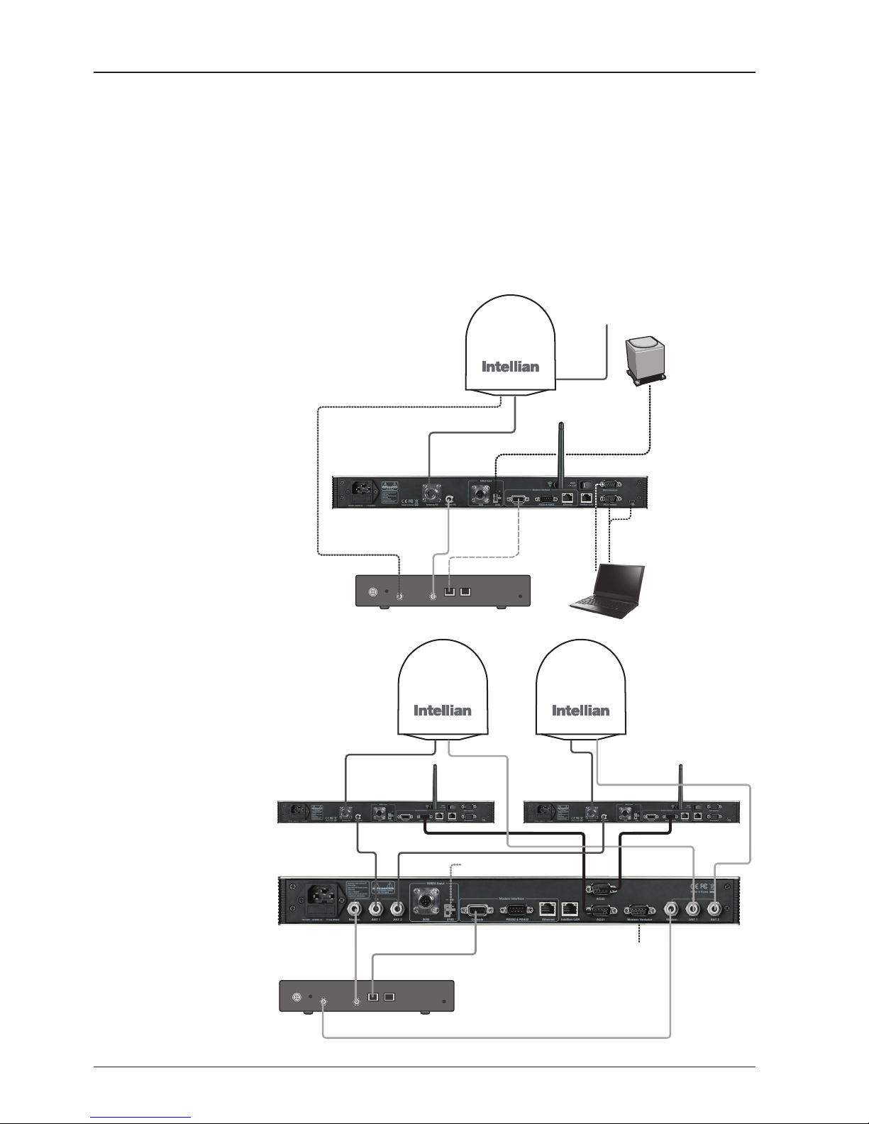
System Conguration
For your satellite communication system to work properly, the system will have to
be connected with all of the provided components as shown in the gure below.
Separate purchase of a satellite modem, ship’s gyrocompass, and Intellian Dual
VSAT Mediator may be required.
Basic System
Configuration
Dual System
Configuration
AC 100 ~ 240V
(50~60Hz, 1A)
AC 100 ~ 240V
(50~60Hz, 4A)
Ship’s Gyrocompass
(Not supplied)
Ship’s Gyrocompass
(Not supplied)
Modem Tx
Modem Rx
Modem Rx 2Modem Rx 1
Modem Rx
Modem Tx
Modem
Interface
Modem
Interface
Modem Tx
Antenna Rx
Antenna Rx 1
Antenna Rx 2 Antenna Tx 2
Antenna Tx 1
NMEA
Antenna Control Unit
Antenna Control Unit 1
Mediator
Antenna Control Unit 2
Satellite Modem
(Not supplied)
Satellite Modem
(Not supplied)
BUC
InterfacePCInterface
PC
PC
AC 100 ~ 240V
(50~60Hz)

13
INTRODUCTION
INSTALLING THE ANTENNA
System Package
Antenna Unit
ACU (Antenna Control Unit)
Installation Kit
Planning the Installation
Selection of Antenna Installation Site
Congure Radiation Hazard/Block Zones
System Cables
Power Requirement
Tools Required for Installation
Antenna Installation
Unpacking the Wooden Crate
Antenna Dimensions
Antenna Mounting Templates
Position the Radome
Mount the Radome
RF Cable Connections
Secure the RF Cables

v100 – Marine Satellite Communication System
14
System Package
The package of Intellian v100 consists of antenna unit, lifting straps, ACU and
installation kit box.
Antenna unit
ACU
Installation kit box

15
INSTALLING THE ANTENNA
Antenna Unit
The antenna unit includes an antenna pedestal inside a radome assembly unit. The
pedestal consists of a satellite antenna main dish with RF components mounted
on a stabilized pedestal. The radome protects the antenna pedestal assembly unit
from the severe marine environment.
Antenna Unit

v100 – Marine Satellite Communication System
16
ACU (Antenna Control Unit)
The digital VFD (Vacuum Fluorescent Display) allows for easy operation of the ACU,
even in the dark.
The functions of the ACU are as follows :
• Setting the satellite
• Editing satellite information
• Setting the antenna parameter
• Setting the antenna manual search
• Setting the LNB local frequency
• Setting radiation hazard or block zone
• Setting modem connections
• Setting GPS and Gyrocompass
• Display power status
• Built-in real-time diagnostics function
• Backup and restore the system settings
• Set up the interface with a PC
• Supports Wi-Fi ACU operation
• Recording antenna activities and rmware upgrade through USB
• Built-in web-based remote control management
• Front panel Management Ethernet port
Antenna Control Unit
Rear panel
Front panel

17
INSTALLING THE ANTENNA
Contains the items required for securing the antenna unit and ACU to the vessel.
Installation Kit
ACU box
Description Q'ty Size Remarks
Antenna Control Unit (ACU) 1 43.1 x 38 x 4.4cm Antenna Control Unit
User Manual 1
RF Hazard Sticker 1 Radiation Safety Distance Label
Mounting Tamplate 1
Wi-Fi Antenna 1 110mm
USB Flash Drive 1

v100 – Marine Satellite Communication System
18
Components box
Description Q'ty Size Remarks
ACU Bracket (Rack) 2 ACU-19inch Rack
ACU Bracket (Table) 2 ACU-Table
RG6 Cable 1 3m ACU to Modem
AC Power Cord (CEEE7/7) 1 1.5m ACU Power
AC Power Cord (USA) 1 1.8m ACU Power
AC Input Cable to Power Box 1 3m AC Power to Antenna Power Box
PC Serial Cable 1 1.8m ACU to PC
USB Cable (A-A) 1 1.8m ACU to PC
Ethernet Cable (RJ45/LAN) 1 1.8m ACU to PC
iDirect Interface Cable 1 1.5m ACU to modem
D-sub 9 pin Male Connector 2 - ACU
N to F Adaptor 1 N(Male) to F(Female) Adaptor
Hex Bolt 5 M12 x 100L
Antenna-Deck 4 Sets :
Installation 1 Set : Spare
Flat Washer 5 M12
Spring Washer 5 M12
Hex Nut 10 M12
Hex Head Wrench Bolt 5 M6 x 40L
Radome (Spare Bolts)Spring Washer and Flat Washer 5 M6
Sems Bolt 2 M4 x 8
Self-Tapping Screw 5 M4 x 16 Table Mount Bracket
Flat Head Screw 10 M4 x 12L Rack Mount Bracket ACU
Sems Bolt 5 M3 x 12L Table Mount Bracket ACU

19
INSTALLING THE ANTENNA
Planning the Installation
Selection of Antenna Installation Site
Install the antenna in accordance with the following procedures to insure maximum
performance of the antenna. The ideal antenna site has a clear view of the horizon
or satellite all around. Please be sure there are no obstacles within 15º above the
center of the antenna. Any obstacles can prevent the antenna from transmitting and
receiving the satellite signal.
Do not install the antenna near the radar especially on the same plane as its energy
levels may overload the antenna front-end circuits. It is recommended to position
the antenna at least 4 feet (1.2 m) above or below the level of the radar and minimum
of 15 feet (4.6 m) away from the high power short wave radars.
The mounting platform should be rigid enough and not subjected to excessive
vibration. The movement of the antenna can be minimized by installing at the
center of the vessel. If these conditions can be only partially satised, nd the best
compromised installation site between the various considerations.
Elevation Limit
of Obstacles
15°
Antenna Unit
Obstacle

v100 – Marine Satellite Communication System
20
Congure Radiation Hazard/Block Zones
It is important to set up the radiation hazard or block zones for Intellian VSAT
communication systems. The ACU can be programmed with relative azimuth and
elevation sectors to create up to ve zones where transmit power would endanger
personnel who are frequently in that area or blockage exists. Several things happen
when the antenna is within one of these zones.
1. “BLOCK” will be displayed on the ACU screen.
2. Tracking continues as long as the signal level is greater than the predened
threshold value. When the signal level drops below the threshold value the
antenna will wait “Search Wait Time” parameter amount of time and re-target the
satellite you targeted last. The antenna will continue to re-target the satellite until
the satellite is re-acquired and tracking can be resumed.
3. A transmit inhibit output from the ACU will disable/mute the modem transmission.
RF Hazard Precautions
The antenna is designed to be used with radiation transmit equipment manufactured
by others. Exposure to RF radiation, including exposure associated with an improper
use of the transmit equipment, may be hazardous to persons close to the above
deck unit. Ensure safety of personnel who work on the system.
During transmission, ensure to keep the minimum safety distance. The recommended
minimum safety distance to the reector on the focal line is about 15m, based on a
radiation level of 5mW/ cm2 that applies under occupational/controlled environment.
No hazard exists >20° below the antenna’s mounting plane.
Safe access from radiation hazard

21
INSTALLING THE ANTENNA
System Cables
Before installing the system cables, you need to take the following points into
consideration.
1. All cables need to be well clamped and protected from physical damage
and exposure to heat and humidity.
2. Cable with an acute bend is not allowed.
3. Where a cable passes through an exposed bulkhead or deck head,
a watertight gland or swan neck tube should be used.
Power Requirement
Intellian v100 has been designed to work on a vessel’s power supply rated at
100-240V AC.
• RF Cable (Customer Furnished)
Due to the voltage losses across the length of the RF coax on L-Band, Intellian
recommends the following 50 ohm coax cable types for standard system
installations. For cables that run longer than 200 meters, please consult Intellian
Technologies.
Recommended
RF Cables
Coaxial Cable
Type
Attenuation in
dB/100M
Attenuation in
dB/M
Recommended
Cable Length
LMR300 30.3 0.303 35M
LMR400 19.6 0.196 60M
LMR500 15.9 0.159 80M
LMR600 12.8 0.128 100M
LMR900 8.6 0.086 150M
LMR1200 6.5 0.065 200M

v100 – Marine Satellite Communication System
22
Tools Required for Installation
Power Drill
Phillips Head Screwdriver
Flat Head Screwdriver
Head Screwdriver
(for Power drill)
11 mm Wrench
19 mm Wrench
5 mm Allen/Hex key
5 mm Allen/Hex key
(for Power drill)

23
INSTALLING THE ANTENNA
Antenna Installation
Unpacking the wooden crate of v100
1
2
3
Tips : Using a Flat-head
screwdriver, remove the clip
as shown in the picture.
Step 1.
When uncrating the wooden crate, follow the procedures below.
1. Locate one of the side panels designed for fork lift. Detach this side panel by removing
the xing screw (1EA) and clips (8EA).
2. Remove the xing screws (4EA) and clips (6EA) on the top panel. Detach the top panel
by carefully pulling it as shown in the picture below.
CAUTION : The side brackets at the edge of the top panel secure the side panels and top
panel in position. When pulling the top panel, ensure that the top panel doesn't fall on the
radome.
3. Remove the xing screws (5EA) from the remaining side panels, then detach the side
panels with clips on.

v100 – Marine Satellite Communication System
24
Step 2.
Remove 8 tapping screws that mount the ACU box and installation kit box to the pallet.

25
INSTALLING THE ANTENNA
Step 3.
Using a 19mm wrench, remove 4 shipping bolts that mount the antenna to the pallet.
WARNING: When lifting the antenna by using the lifting strap, ensure to disassemble
the antenna and the pallet.

v100 – Marine Satellite Communication System
26
Step 5.
Open the top radome and remove the shipping restraints.
Step 4.
Open the radome hatch.
Flat-Head Screwdriver
(min 5mm)
Radome Hatch
A. Remove shipping brackets securing the Skew, AZ axis and EL axis.
1
2
3
1. Remove the Skew Shipping Bracket
2. Remove the AZ Shipping Bracket
3. Remove the EL Shipping Bracket

27
INSTALLING THE ANTENNA
Antenna Dimensions
The method of installation and mounting of antenna may vary with vessel design
but the following procedures are applicable in most situations, and will result in a
secure and effective installation. Conrm the height and diameter of the antenna
before installing it.
Radome Dimensions
B. Remove the shipping brackets securing the CL axis.
C. Re-assemble the top radome and tighten the radome retention bolt (M6) to
a torque setting of 3.5 N·m. To ensure security, apply Loctite #242 or equivalent.
Remove the shipping brackets
138 cm (54.33”)
151.48 c m (59.64”)

v100 – Marine Satellite Communication System
28
Cable Entry
Hatch
Radome Bottom
Radome Hatch
ø44.5cm (17.5”)
BOW
Antenna Mounting Templates
The mounting holes must be in the exact same place as shown in the diagram
below.
Bow direction

29
INSTALLING THE ANTENNA
Antenna
Mounting Hole
Pattern
24.75cm (9.74”)
ø44.5cm (17.5”)
ø44.5cm (17.5”)
24.75cm (9.74”)
4-ø13 Holes

v100 – Marine Satellite Communication System
30
Mounting plate
Min. 1cm(0.4”)
Max. 3cm(1.2”)
Support Pedestal
Appr. ø25.4cm(10”)
Min 60cm(24”)
Max 150cm(60”)
Position the Radome
The radome should be positioned with the BOW marker aligned as closely as
possible to the ship’s centerline.
Recommended size of the
support pedestal

31
INSTALLING THE ANTENNA
Mounting the Radome
Bolt the radome base directly to the support pedestal.
Deck
M12 Flat Washer
M12 Spring Washer
M12 Hex Nut
M12 Hex Nut
19mm Wrench
M12 Hex Bolt
Antenna Unit
RF Cable Connections
Ensure that the switch on the power switch box is off during the installation period.
When all the cables have been installed, turn on the switch.
Note: Make sure to use the Intellian supplied bolts from the accessory box when you
mount the radome. Apply Loctite #262 or equivalent to the bolt thread, and fasten it
to a torque setting of 110 N·m.
Cable Gland O-ring
Shrinkage Guide
Rubber Gland

v100 – Marine Satellite Communication System
32
Cable Connections on
Power Switch Box
Antenna
Power Cable
(From Antenna)
Rotary #2
Rx Cable
(From Antenna)
ACU Rx Cable
(From ACU)
Modem Tx Cable
(From Modem)
Rotary #1
Tx Cable
(From Antenna)
Antenna
Power Cable
(From Ship's
power)
NOTE:
• Intellian recommends the following size of the input power cable for standard system
installations.
• After connection, seal the cable gland and tie the power cable securely in place.
• The antenna power is supplied from the power switch box equipped with the circuit
breakers, and the power switch box should be installed near the antenna.
Cable Length Cable Cross Sectional Area AWG (American Wire Gauge) Size
Up to 100m 2.62mm
2
13
Up to 200m 4.17mm
2
11
NOTE: Tightening torque
Connector Type Tightening Torque
F Type 1.0 N-m
SMA 0.6 N-m
N Type 1.5 N-m

INSTALLING THE ACU
Mounting the ACU
19” Rack Mount Type
Table Mount Type
ACU Dimensions
Selection of ACU Installation Site
Gyrocompass Connection
Connecting the System with a Gyrocompass
Connecting the System without a Gyrocompass
PC to ACU Communication Setup
TCP/IP Connection
Wi-Fi Connection
Setup Wi-Fi Connection
Setting up the ACU in order to access Wi-Fi
Setting up the PC in order to access Wi-Fi
ACU Connector Guide

v100 – Marine Satellite Communication System
34
Mounting the ACU
Intellian supplies two types of mounting methods (a) 19” Rack Mount Type and (b)
Table Mount Type to mount the ACU.
19” Rack Mount Type
- The ACU should be installed using the two supplied Rack Mounting Brackets
which allow for a side 19” rack mounting conguration.
- Using the Flat Head Screw supplied, attach the mounting brackets to the sides of
the ACU.
- Place the ACU in the location where it is going to be installed.
- Connect the cables to the rear of the ACU.
Table Mount Type
- The ACU should be installed using the two supplied Table Mounting Brackets
which allow for a top or bottom mounting conguration.
- Using the Sems Bolt supplied, attach the mounting brackets to the sides of the
ACU.
- Place the ACU in the location where it is going to be installed.
- Using a pencil to mark the 4 hole positions (2 each side), and use the appropriate
drill bit to screw down the brackets.
- Connect the cables to the rear of the ACU.
WARNING: Ensure that the cables connected to the ACU are long enough to prevent
damage when the ACU is pulled out from the rack.
19" Rack Mount Type
Table Mount Type

35
INSTALLING THE ACU
Selection of ACU Installation Site
The ACU should be installed below deck, in a location that is:
• Dry, cool, and ventilated.
• The front panel should be easy accessible to user.
ACU Dimensions
Dimension of ACU
48.5 cm (19.1")
46.6 cm (18.4")
3.2 cm (1.3")
13.0 cm (5.1")
43.1 cm (17")
47.5 cm (18.7")
20.0 cm (7.9")
45.5 cm (17.9")
38 cm (15")
4.4 cm (1.7")

v100 – Marine Satellite Communication System
36
Gyrocompass Connection
Connecting the System with a Gyrocompass
The ship’s gyrocompass provides true heading input to the antenna which easily
allows the antenna to target and acquire the desired satellite. Intellian always
recommends to connect a gyrocompass to the antenna through the gyrocompass
interface on the ACU. If the ship’s gyrocompass output is other than NMEA 0183
and NMEA 2000, separate purchase of an NMEA converter is required.
Recommended Cable
• NMEA 0183 / NMEA 2000 Gyrocompass Cable (Customer supplied)
• Connector Type: 2 conductors for NMEA 0183, 5 conductors for NMEA 2000
• NMEA heading sentence: xx HDT (4800 Baud, 8, N,1)
If there is no HDT sentence, then use HDM sentence instead.
• NMEA 2000 heading PGN Number = 127250 (Vessel Heading)
Gyrocompass Connection
Strip the cable for 5 mm (0.2")
Do not solder the cable

37
INSTALLING THE ACU
Connecting the System without a Gyrocompass
For a vessel where the ship’s gyrocompass is not installed or is difcult to be
connected, the Intellian Gyro-Free satellite search function will be automatically
enabled to allow the antenna to lock onto the desired satellite without requiring an
external heading input.
The table below provides an example of the Gyro-Free satellite search algorithm.
The Search 1 or Search 3 satellite search pattern will be triggered according to the
existence of heading input and the setting of the heading device.
Search 1: The antenna will search for the target satellite by turning its azimuth
angle in CCW(Counter Clockwise) direction until the antenna receives
the lock signal from the modem or the DVB(Digital Video Broadcasting)
transponder of the target satellite is decoded by the antenna.
Search 3: The antenna will search for the target satellite by turning its azimuth angle
directly to the position calculated using the ship’s heading input and lock
onto the satellite.
Quick Setup Procedure
• Set the satellite with DVB transponder as the target satellite.
• Set “No Device” to the heading device.
• The antenna will search for the target satellite by turning its azimuth angle in CCW
direction and lock onto the satellite signal until the antenna receives a lock signal
from the modem or the DVB transponder of the target satellite is decoded.
• Set the heading device as NMEA.
• Enter “Manual search” menu and touch “Function” key to save the current settings.
Intellian ACU will automatically calculate and save the bow offset.
• Upload the real TARGET satellite pre-congured from the library.
Setting of Heading Device
Existence of Heading Data No Device
NMEA /
NMEA 2000
Ground Test
With Heading Data
Search 1 Search 3 Search 3
Without Heading Data
Search 1 Search 1 Search 3

v100 – Marine Satellite Communication System
38
PC to ACU Communication Setup
You can establish data communication between a PC and the ACU using one
of the following methods.
TCP/IP Connection
Connection through Front Panel Management Port
This method is most recommended. Network is automatically congured by DHCP
without the need of additional PC IP conguration nor intervention to Modem to
ACU connection in use.
1. Connect an Ethernet cable from a PC Ethernet port to the Management port
on the front of the ACU.
2. Network connection is established.
3. Use the following IP address to access Intellian Aptus® or Aptus Web page.
• 192.168.2.1 (Default)
Connection through Rear Panel Ethernet Port
This method requires separate IP conguration on a PC.
1. Connect an Ethernet cable from a PC Ethernet port to an available LAN port
of a Switch/Hub.
2. Go to Control Panel > Network and Sharing Center > Change Adapter Settings
and right-click on the Local Area Connection then click Properties
3. Select TCP/IPv4, then click Properties.
4. Change the network settings on a PC;
• Default IP: 192.168. 0.222 (Secondary: 10.10.1.2)
• Subnet Mask: 255.255.255.0
• Gateway: 192.168.0.223 (Secondary: 10.10.1.1)
5. Use the following IP address to access Intellian Aptus® or Aptus Web page.
• Default: 192.168.0.223 (Secondary: 10.10.1.1)
PC
Management
Ethernet Port
Ethernet Port

39
INSTALLING THE ACU
Serial/USB Connection
Connection through Serial Port
1. Connect a 9-pin Serial cable from the PC INTERFACE connector on the
ACU to the 9-pin serial port on your PC.
2. If there is not a 9-pin serial port on the PC, use a USB-Serial adapter.
3. To access Intellian Aptus
®
, see Aptus section.
Connection through USB Port
There are two USB(USB-to-Serial) ports are available on the ACU. One is on the
front and the other is on the rear.
1. Connect a USB cable from a USB port on your PC to the USB port
on the ACU.
2. To access Intellian Aptus
®
, see Aptus section.
Serial Connection
USB Connection

v100 – Marine Satellite Communication System
40
Wi-Fi Connection
1. Turning on the Wi-Fi switch
Turn on the switch on the back of the ACU, and 30 seconds after enabling the
power supply, conrm if a red light appears on the switch.
Setup Wi-Fi Connection
• Setting up the ACU in order to access Wi-Fi
• Setting up the PC (Adhoc Mode) in order to access Wi-Fi
• Remote Access Conrmation
Setting up the ACU in order to access Wi-Fi

41
INSTALLING THE ACU
2. Change the network settings to the settings listed below.
Case #1
If iARM Module’s IP is known
The iARM module’s default IP is 192.168.1.223
PC IP : 192.168.1.222
Subnet Mask : 255.255.255.0
GateWay : 192.168.1.223
Case #2
If iARM Module’s IP is unknown
The iARM module’s secondary IP is 10.10.10.1
PC IP : 10.10.10.2
Subnet Mask : 255.255.255.0
GateWay : 10.10.10.1
Setting up the PC in order to access Wi-Fi
1. Setting up my computer’s wireless IP address
- Control Panel> Network and Sharing Center > Change Adapter Settings >
Right click on the “Local Area Connection”> Click Properties
After selecting TCP/IPv4, click on the properties menu.
v100 – Marine Satellite Communication System
42
3. Connect WIFI in Ad-hoc mode.
After clicking on the Windows Wireless Connection icon, click on intellian-WIFI
(Default)
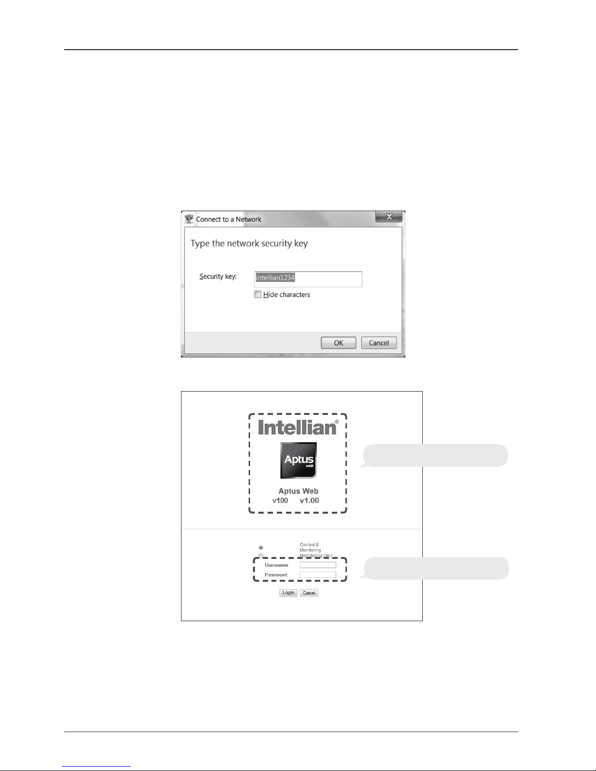
4. Enter the Network Security Key.
Key: intellian1234 (Default)
Login by entering the ID / Password listed below.
Username: intellian (Default)
Password: 12345678 (Default)
6. When you login, make sure that all the data within every page is being displayed
correctly.
5. You can conrm the logo and version data by accessing http://192.168.1.223
Aptus Web v X.XX
Login intellian / 12345678

43
INSTALLING THE ACU
ACU Connector Guide
• Console Port
NOTE: NMEA GPS IN/OUT Sentence: GPGLL (4800 Baud, 8, N, 1)
12345
6789
54321
9876
54321
9876
54321
9876
Pin Signal Pin Signal
1 GND 6 GPS OUT -
2 GPS OUT + 7 MODEM_SIGNAL_IN
3 MODEM_LOCK 8 MODEM_CTRL2
4 MODEM_CTRL1 (TX MUTE) 9 GPS IN -
5 GPS IN +
ACU Console Port
D-Sub 9 pin Female
D-Sub 9 pin Male connector
Supplied Component
Pin Signal Pin Signal
1 - 6 -
2 RXD 7 -
3 TXD 8 -
4 - 9 -
5 GND
Pin Signal Pin Signal
1 - 6 -
2 RXD + 7 RXD -
3 TXD + 8 TXD -
4 - 9 -
5 GND
D-Sub 9 pin RS232
Connector
D-Sub 9 pin RS422
Connector
• RS232/422 Connector (Modem & BUC Interface)

v100 – Marine Satellite Communication System
44
• NMEA 2000 Connector
5
4
3
2
1
Pins
Connector Threads
5
3
4
1
2
Sockets
Connector Threads
Pin Signal
1 Shield
2 NET-S, (power supply positive, +V)
3 NET-C, (power supply common, -V)
4 NET-H, (CAN-H)
5 NET-L, (CAN-L)
Pin Signal
1 Shield
2 NET-S, (power supply positive, +V)
3 NET-C, (power supply common, -V)
4 NET-H, (CAN-H)
5 NET-L, (CAN-L)
Male Connector Female Connector

OPERATING THE ACUOPERATING THE ACU
Introduction
Normal Mode
Setup Mode
Installation Settings
Antenna Settings
Manual Search
Setup Antenna LNB Polarization Angle
Search Parameters
Setup Antenna Parameters
Setup Block Zone
Antenna Diagnostic Test
Satellite Settings
Load Satellite
Edit Satellite Information
Add Satellite Information
Check NID
System Settings
Set LNB Local Oscillator Frequency
Set Location
Set Modem Port
System Backup & Restore
Display Versions

v100 – Marine Satellite Communication System
46
This section of the handbook describes how to setup your system after installing
the ACU. It includes the following functions:
Introduction
Mode Function
Normal Mode
Startup
Monitoring current antenna status
Setup Mode
Installation settings
Selecting satellite
Setting GPS and Gyrocompass
Setting Bow adjustment
Setting Modem connection
Setting LNB Local Frequency
Antenna settings
Antenna manual search
Setting Antenna LNB Pol Angle
Setting Antenna Search parameters
Setting Antenna parameters
Setting block zone
Performing diagnostic tests
Satellite settings
Load Satellite
Edit satellite information
Add Satellite
System settings
Setting LNB Local Frequency
Setting GPS and Gyrocompass
Setting Modem port
System management
Setting Key lock
NOTE: Many of the above functions will only be required after initial installation of
your system.

47
OPERATING THE ACU
ACU Front Keys
Touch Key Functions
PC : PC Cable (USB)
DN : Firmware upgrade or Log data
download (USB)
Management port
Arrow
Keys
Function
OK
BACK
Number Keys
Power
Switch
MENU
Touch key Function
MENU
Enter SETUP mode
BACK
In SETUP mode, returns to previous menu or option or saves the
adjusted settings.
In Normal mode, returns to the rst page of antenna current
status.
FUNCTION
Saves the adjusted settings.
Arrow keys
Selects from the alternative options to increase or decrease the
selected character to a desired value.
OK
Enter next step / menu
Number keys
Inputs the numbers.

v100 – Marine Satellite Communication System
48
I NT E LL I AN T EC H NO L OG IES IN C.
1. The data communication is being established between the antenna and the ACU.
IN I TI A LI Z E - ANTE NN A INFO
IN T EL L IA N v100
2. The ACU receives antenna information.
IN I TI A LI Z E - EL POS I TI O N
IN T EL L IA N v100
3. The elevation angle and cross level angle are initialized.
IN I TI A LI Z E - AZIM UT H PO SI T IO N
IN T EL L IA N v100
4. The azimuth angle is initialized.
IN I TI A LI Z E - SAT P OS I TI O N
IN T EL L IA N v100
5. The antenna returns to the target satellite position.
S EA R CH 1 138. 0E T ELS T_1 8 SIG : 30 1 VL
A Z: 2 92 . 7( 20 2.7 ) E L: 4 8. 3 SK: - 72 . 0
6. The antenna is searching for the target satellite.
T RA C KI N G 138 .0E TE LST _1 8 SI G: 5 01 VL
A Z: 2 92 . 7( 20 2.7 ) E L: 4 8. 3 SK: - 72 .0 F n
7. The antenna has locked onto the satellite.
Startup
With the system installed and power applied, the ACU screen will show the following
sequence.
Normal Mode
Start up
Initialize antenna info
Initialize elevation &
cross level angle
Initialize azimuth angle
Initialize target satellite
position
Search status
Tracking status

49
OPERATING THE ACU
S EA R CH 1 138. 0E T ELS T_1 8 SIG : 30 1 VL
A Z: 2 92 . 7( 20 2.7 ) E L: 4 8. 3 SK: - 72 . 0
1. The antenna is searching for the target satellite.
T RA C KI N G 138 .0E TE LST _1 8 SI G: 3 01 VL
A Z: 2 92 . 7( 20 2.7 ) E L: 4 8. 3 SK : - 7 2. 0 Fn
2. The antenna has locked onto the target satellite.
Current IF signal level (SIG/dB scale/AGC) is displayed. SIG and dB scale will be displayed
when NBD (Narrow band detection) mode for TRACKING SIGNAL is chosen to be used and
AGC will be displayed when DVB mode of TRACKING SIGNAL is chosen to be used.
The symbol “•” will be only displayed when the satellite signal is strong enough to locked
onto. [VL] indicates the LNB's local frequency corresponding to 13V is in use for the signal
reception.
VL: 13V + 0 kHz, HL: 18V + 0 kHz, VH: 13V + 22 kHz, HH: 18V + 22 kHz
Touch the UP or DOWN arrow key to increase or decrease the LNB pol angle. UP or DOWN
arrow key can be displayed or hidden by touching OK button 3 times consequently. Pol angle
can be adjusted only when UP or DOWN arrow key is displayed (enabled). True azimuth
[292.7] position of the antenna is the sum of ships heading 090.0 [HDG] and antenna relative
[202.7].
SA V E C U RR E NT S AT INF O ?
YE S N O
3. Touch FUNCTION key to save current satellite information or abort and return to the main
display. "Fn" will be displayed only if the antenna is in tracking mode.
NOTE: However, if the "GYRO TYPE" is set to "NONE" or "NMEA" but without
receiving a proper input signal, "---.-" will be displayed at "True Azimuth"
Monitoring Antenna Current Status
When the ACU power is on, it displays the status of the antenna. The current status
of the antenna is displayed as shown below.
Current search status
Current tracking status
Save current satellite info

v100 – Marine Satellite Communication System
50
4. Touch RIGHT arrow key to display NBD, GPS and ship’s heading information.
5. NBD, GPS and ship’s heading information are shown.
- NBD (Narrow Band Detection) IF tracking frequency: 1247000 kHz
- Detected Band Width: 1000 kHz
- SIG/dB scale (Signal Level ): 140/14.0dB (When NBD mode for tracking signal is chosen)
- W (West)/E (East) Longitude: 4.53º E
- N (North)/S (South) Latitude: 52.22º N
- HDG (Ship’s Heading): 90º
- LNB local oscillator (LO) frequency: 10000 MHz
V3-1 1B- PJ W A NT SE RI A L 1. 0 0( 1 .0 0 )
VP-T 537 AC U S E RI A L 1. 00
7. Touch RIGHT arrow key to display the below information.
- Antenna part number, antenna serial number and PCU and Stabilizer rmware version.
- ACU part number, ACU serial number, ACU rmware version and Library version.
Touch BACK Key to return to the rst page of the antenna current status.
Tracking & Heading
information
Antenna & ACU
versions
T RA C KI N G 138 .0E TE LST _1 8 SI G: 3 01 VL
A Z: 2 92 . 7( 20 2.7 ) E L: 4 8. 3 SK : - 7 2. 0 Fn
N BD F:1 247 000 B W: 1 00 0 SI G :3 0 1
0 04 . 53 E 52. 2 2N H DG: 090 .0 L: 10 0 00 Fn
Current tracking status
8.Touch RIGHT arrow key to display the USB FUNCTION*
This menu will be displayed automatically if a USB ash drive is plugged into the USB port
located in the front panel of the ACU.
USB FUNCTION*
• UPGRADE FIRMWARE: upgrade the system by using the rmware les
(les format: *.FWP) from the specied folder in the USB ash drive.
• COPY LOG DATA: Copy the up-to-date log data from the system to the USB ash drive.
Select
USB
functions
[ US B FUN C TI O N] SELE CT U SB FU NC T IO N
UP G RA D E F IRM WAR E

51
OPERATING THE ACU
9. Touch OK key to upgrade rmware.
Refer to the error messages below if any errors occur.
UPGRADE FIRMWARE
- FIRMWARE FILE NOT FOUND: the system cannot nd the FWP le.
- INVALID FIRMWARE: the le is not in a recognizable FWP format.
- MORE THAN 1 FILE EXIST: there is more than 1 rmware le that exists from the
specied folder in the USB ash drive.
- CHECK USB CONNECTION: the USB ash drive is not connected.
COPY LOG DATA
- COPY LOG DATA TO USB [30%]: display the copy progress in percentages.
- NOT ENOUGH SPACE IN USB: USB occupies no memory space.
- CHECK USB CONNECTION: the USB ash drive is not connected.
10. Touch RIGHT arrow key to display the real-time diagnostic result.
The real-time diagnostic code will be displayed automatically if there is any error found
during the system operation. However, this page will not be displayed if there is no error
message.
11. Touch FUNCTION key to erase diagnostic error message.
Real-time
diagnostic
result
Erase
Error message
Upgrade
the
system
[ DIA GNO STI C] S EN S OR BO X
COD E 10 9 RES ULT S : FA IL E D FN
UP G RA D E ?
YE S N O
ER A SE DI AG N OS T IC E RR OR L OG ?
YE S N O
USB

v100 – Marine Satellite Communication System
52
Setup Mode
Enter the SETUP mode simply follow the instructions below.
Searching / Tracking mode
Enter password
Setup mode
Exit setup mode
T RA C KI N G 138 .0E TE LST _1 8 SI G: 3 01 VL
A Z: 2 92 . 7( 20 2.7 ) E L: 4 8. 3 SK: - 72 . 0 Fn
1. While the antenna is in SEARCHING/TRACKING mode, touch MENU key to enter SETUP
mode.
*
indicates the key pad lock function is on (Refer to KEY LOCK menu to setup the key
pad lock function). When key pad lock function is activated touch MENU key or when “Fn”
menu is activated touch FUNCTION key then ENTER PASSWORD menu will be displayed.
EN T ER P AS S WO R D
- - - -
2. If the key pad lock function is on, enter the password before accessing to the SETUP
mode. If the key pad lock function is off, access to the SETUP mode directly as Step 3.
S ET U P MOD E ?
YE S NO
3. Touch LEFT arrow key to move cursor to YES and touch OK key to enter SETUP mode or
touch RIGHT arrow key to move cursor to NO and touch OK key to abort and return to the
main display.
E XI T SETU P MOD E ?
YE S NO
4. While the antenna is in SETUP mode, touch FUNCTION key as shortcut key to exit SETUP
mode.

53
OPERATING THE ACU
Installation Settings
During the rst time installation, it is required to setup the installation settings.
Installation
menu
Latitude & Longitude
Gyro type
Select satellite
Setup mode
S ET U P MOD E ?
Y ES N O
1. Touch LEFT arrow key to move cursor to YES and touch OK key to enter SETUP mode
+ AN T EN N A +SA TEL LIT E
+ SY S TE M
+I N ST A LL A TI O N
2. Touch arrow keys to move cursor to INSTALLATION menu and touch OK key to enter it.
S EL E CT S AT E LL I TE
[1] TE LST _18 138. 00E
3. Touch UP and DOWN arrow keys to select the satellite that you wish to track and touch
OK key to load the selected satellite.
L AT I TU D E LON GIT UDE
3 7. 0 0N 1 26 . 53 E
4. Set the current LATITUDE and LONGITUDE
Touch LEFT and RIGHT arrow keys until the desired character is underscored (selected).
Touch UP and DOWN arrow keys to increase or decrease the value. Or touch NUMBER keys
to set the desired value directly. Touch OK key to set the parameter.
GYR O TYPE BOW O FFS ET
NME A 00 0
5. Set the ship’s GYRO TYPE* & BOW OFFSET
A search pattern 1 or 3 will be initiated according to which gyrocompass type is selected and
the existence of the gyrocompass input. Ensure that the supported gyrocompass type is set
correctly. If the ship's gyrocompass output is different than NMEA, A search pattern 1 will
be initiated automatically if the gyrocompass input does not exist and the gyrocompass type
that is selected is different than GROUND TEST.
The BOW OFFSET is to offset the angle difference between the antenna’s bow and the ship’s
bow (Range: 0 – 360°).
NOTE: The bow offset will not be saved automatically if Search 1 pattern is initiated. In this case, the
antenna will need to retarget the desired satellite using Search 1 every time if the antenna restarts.

v100 – Marine Satellite Communication System
54
6. MODEM TYPE 1) is to select a proper data communication port and protocol on the ACU
to interface with the satellite modem. The settings related to the modem interface will be set
automatically once the modem type is selected.
The options on the next page will be displayed and required to be set if "USER SETTING" is
selected.
1 8V + 0KH Z 13V + 22 K HZ
1 07 5 0M H Z 113 0 0M H Z
1 8V +22K HZ
1 13 00M HZ
7. Set the LNB local oscillator frequency for each voltage power. (13V +0 kHz, 18V +0 kHz,
13V +22 kHz, 18V +22 kHz)
Set modem type
and LNB local frequency
LNB local frequency
GYRO TYPE*
NO DEVICE
NMEA
NMEA 2000
GROUND TEST
Gyro search mode
MODEM TYPE*
• USER SETTING
• IDIRECT-I/O
• IDIRECT-AMIP
• COMTECH-I/O
• COMTECH-ROSS
• HUGHES
• SATLINK-SERIAL
• SATLINK-VACP
• ELEKTRIKOM-AMIP
• GILAT-SE-II
• IPSTAR-SOTM
Setting of Heading Device
Existence of Heading Data No
Device
NMEA/
NMEA 2000
Ground Test
With Heading Data
Search 1 Search 3 Search 3
Without Heading Data
Search 1 Search 1 Search 3
M OD E M TYP E 13 V + 0K Hz
IDI R EC T -I / O 100 0 0 M H z

55
OPERATING THE ACU
T RA C KI N G 138 .0E TE LST _1 8 SI G: 3 01 VL
A Z: 2 92 . 7( 20 2.7 ) E L: 4 8. 3 SK: - 72 . 0 Fn
10. Antenna has locked onto the target satellite.
Tracking status
L OA D IN G ...
D O NOT TUR N OFF !
9. Setting is being loaded to the system.
The ACU will restart the system automatically after uploading the setting.
DO NOT TURN OFF ACU POWER while the data is being uploaded.
Loading settings
L OA D ?
Y ES N O
8. Touch BACK key to load the current setting or abort and return to the main display.
Load

v100 – Marine Satellite Communication System
56
Antenna Settings
Manual Search
Search the desired satellite manually.
Antenna movement
Setup mode
Save
Manual search menu
Antenna menu
S ET U P MOD E ?
Y ES N O
1. Touch LEFT arrow key to move cursor to YES and touch OK key to enter SETUP mode.
+ ANT ENN A +SA T EL L IT E
+ SY S TE M +INS TAL LAT ION
2. Touch OK key to enter ANTENNA menu.
+MA N UA L SEAR CH + SET PO L A NGL E
+ SE A RC H PARA M +SE T PA RA MET ERS
3. Touch OK key to enter MANUAL SEARCH menu.
S TE P SIZE AZ IM U TH E LE V AT I ON A GC
# 0 0 .2 #
23 1 .7 48.3 3 01 Fn
4. Current IF tracking signal level (AGC)/(SIG/dB scale) is displayed to assist you in manually
peaking AZIMUTH (0°-360°) and ELEVATION (0°-90°) angle for best signal level.
Touch NUMBER key to change the STEP SIZE (Range: 0.1~99.9). Touch LEFT and RIGHT
arrow keys to increase or decrease the azimuth angles. Touch UP and DOWN arrow keys to
increase or decrease the elevation angles.
Touch FUNCTION key to save current settings or abort and return to the main display.
S AV E CURR ENT SA T INF O ?
Y ES N O
5. If the current settings are able to locate the satellite, touch FUNCTION key to save “current
satellite information”. This will help to reduce the satellite acquisition time after restarting
the system. Touch LEFT arrow key to move cursor to YES and touch the OK key to save the
settings.
NOTE: If the gyrocompass type is not NMEA or the gyrocompass is not connected to
the ACU, the information cannot be saved.

57
OPERATING THE ACU
Setup Antenna LNB pol Angle
LNB pol angle type
Setup mode
Set pol angle menu
Antenna menu
LNB pol angle Signal
Mechanical Skew Offset
S ET U P MOD E ?
Y ES N O
1. Touch LEFT arrow key to move cursor to YES and touch OK key to enter SETUP mode.
+ ANT ENN A +SA T EL L IT E
+ SY S TE M +INS TAL LAT ION
2. Touch OK key to enter ANTENNA menu.
+MA N UA L SEAR CH + S ET P OL AN GL E
+ SE A RC H PARA M +SE T PA RA MET ERS
3. Touch RIGHT arrow key to move cursor to SET POL ANGLE menu and touch OK key to
enter it.
SE L EC T LNB PO L . A N GL E ME NU
C A LI B RA T IO N
4. Touch UP and DOWN arrow keys to select the LNB pol angle menu and touch OK key to
run the selected operation 'CALIBRATION', 'MANUAL ADJUST' or 'RESET MECHANICAL
OFFSET'. Select MANUAL ADJUST to control LNB pol angle manually. If the control board,
LNB pol potentiometer or belt is replaced, select CALIBRATION to calibrate LNB pol angle.
If the satellite skew offset is unknown, you may select RESET MECHANCAL OFFSET to reset
the mechanical skew offset (Overall system skew offset = satellite skew offset + mechanical
skew offset).
LN B P OL AN GLE S I GN A L: 1 80
2 0
5. Touch UP and DOWN arrow keys to increase or decrease the LNB pol angle manually and
the correspondent SIGNAL level will be displayed next to it. Touch BACK key to return to the
main display.
NOTE: LNB POL ANGLE menu will be displayed only if MANUAL ADJUST is selected.
SEL E CT LNB PO L. A NG L E M E NU
RE SET ME CHA NIC AL O FF S ET
6. Press OK keys to reset the mechanical skew offset.

v100 – Marine Satellite Communication System
58
Search 3 range
Search 1 range
Search Parameters
Setup mode
Manual search menu
Antenna menu
Search param
SE T UP M OD E ?
YE S NO
1. Touch LEFT arrow key to move cursor to YES and touch OK key to enter SETUP mode.
+AN TEN NA + SAT EL L IT E
+S Y ST E M + I NS T AL LAT ION
2. Touch OK key to enter ANTENNA menu.
+MA NUA L SE ARC H + SE T POL AN GL E
+SE ARC H PA RAM +S E T P A RA M ET E RS
3. Touch arrow keys to move cursor to SEARCH PARAM menu and touch OK key to enter it.
SE A RC H WA I T T I ME INC REM ENT STE P
03 0 0. 50
S EA R CH 1 AZ SEA R CH 1 EL
400 06
S EA R CH 3 AZ SEA R CH 3 EL
003 04
4. Set SEARCH 1 and 3 AZ (Azimuth) range and EL (Elevation) range. SEARCH 2 is reserved
for future use.
A search pattern 1 or 3 will be initiated according to which gyrocompass type is
selected and the existence of the gyrocompass input.
Search 1: A search pattern 1 will automatically be initiated when the ship’s heading
input does not exist/is failed. The antenna will go to the relative azimuth position 0º
at the calculated elevation and search in the azimuth CCW direction and search up
+0.5º & down -0.5º with a total 6º(±3º) in elevation. The search cycle will repeat until
the antenna receives the lock signal from the modem or the DVB transponder of the
target satellite is decoded by the antenna. If the desired signal is found and above
the predened detect level, the ACU will enter to Search 3. However, the antenna
will not initiate Search 3 pattern but go into TRACKING mode immediately if the
desired signal is above the predened tracking threshold level. If the detected signal
is below the predened tracking threshold level, the search 1 will repeat and start 3º
away from the current position.

59
OPERATING THE ACU
-3°
-2°
-1°
0°
1°
2°
3°
1 5 10 15 20 3025
Search 1 (Gyro Free) Search Pattern
Search 3 pattern
Search 3: A search pattern 3 will automatically be initiated when AGC/SIG falls
below the current tracking level threshold value. If the desired signal is found and
above the predened tracking level, the ACU will terminate Search 3 and go into
TRACKING mode. A search pattern will automatically be initiated when AGC/SIG
falls below the current threshold setting (indicates that satellite signal has been
lost). Search is conducted in a two-axis pattern consisting of alternate movements
in azimuth (AZ) and elevation (EL) as forming expanding square indicated as below
diagram.
Target Satellite EL Position
Revolution (AZ direction)
Search 1 antenna motion
Elevation
(EL) Range
0.5˚
Azimuth (AZ) Range
Target EL Angle 0°
Turn 1
Target EL Angle 0°
Turn 3
Target EL Angle + 0.5°
Turn 2
Target EL Angle - 0.5°
Turn 4

v100 – Marine Satellite Communication System
60
Password
Antenna menu
Set parameters menu
Setup mode
Set detect & tracking DVB
Setup Antenna Parameters
These parameters should only be changed by an authorized Intellian service technician.
Improper setting of these parameters will cause your system to perform improperly.
SE T UP M OD E ?
YE S NO
1. Touch LEFT arrow key to move cursor to YES and touch OK key to enter SETUP mode.
+AN TEN NA + SAT EL L IT E
+S Y ST E M + I NS T AL LAT ION
2. Touch OK key to enter ANTENNA menu.
+M A NU A L S E AR C H + S E T POL ANGL E
+S E AR C H P A RA M
+S E T P A RA M ET E RS
3. Touch arrow keys to move cursor to SET PARAMETERS menu and touch OK key to enter it.
EN T ER P AS S WO R D
- - - -
4. Touch 4 digit password to enter SET PARAMETERS menu (1590).
Setup parameters is only required after installation or repairs of your antenna system.
These parameters should only be changed by an authorized service technician.
Improper setting of these parameters will render your system inoperable.
DE T EC T DV B TR A CK I NG D VB
0 4 0 02 0
5. Set DETECT DVB and TRACKING DVB when DVB mode of TRACKING SIGNAL is chosen
to be used (Range: 1-200).
DETECT DVB is to set the satellite signal detection level and TRACKING DVB is to set the
satellite signal tracking level.
Touch LEFT and RIGHT arrow keys until the desired character is underscored (selected).
Touch UP and DOWN arrow keys to increase and decrease the selected character.
Or touch NUMBER keys to set the desired value directly. Touch OK key to set the parameter.
Touch BACK key to select the parameter you wish to edit and touch BACK key again to save
or abort and return to the main display.

61
OPERATING THE ACU
Detect & tracking level
Set detect & tracking NBD
BOW & EL adjust
DE T EC T NB D T RAC KIN G NB D
0 4 0 02 0
6. Set DETECT NBD and TRACKING NBD when NBD (Narrow Band Detection) mode of
TRACKING SIGNAL is chosen to be used (Range: 1-200).
DETECT NBD is to set the satellite signal detection level and TRACKING NBD is to set the
satellite signal tracking level.
Touch LEFT and RIGHT arrow keys until the desired character is underscored (selected).
Touch UP and DOWN arrow keys to increase and decrease the selected character.
Or touch NUMBER keys to set the desired value directly. Touch OK key to set the parameter.
Touch BACK key to select the parameter you wish to edit and touch BACK key again to save
or abort and return to the main display.
Noise Level
Detect Level
Tracking Level
TRACKING DVB/NDB
Peak Level
DETECT DVB/NDB
BO W OF F SE T EL. A DJ U ST
0 0 0 +0 . 0
7. Set BOW OFFSET and EL. ADJUST
BOW OFFSET is to offset the angle difference between the antenna’s bow and the ship’s bow
(Range: 0 – 360°) and EL. ADJUST is to offset the angle difference between the mechanical
elevation angle and actual elevation angle (Range: ± 5°).
Touch LEFT and RIGHT arrow keys until the desired character is underscored (selected).
Touch UP and DOWN arrow keys to increase and decrease the selected character.
Or touch NUMBER keys to set the desired value directly. Touch OK key to set the parameter.
Touch BACK key to select the parameter you wish to edit and touch the BACK key again to
save or abort and return to the main display.

v100 – Marine Satellite Communication System
62
Select operation
process
OP ER ATI ON
SA VE
8. Execute the command of the selected item from OPERATION*.
OPERATION*
• SAVE: save and execute the current settings.
• IDLE ON/OFF: the motor brakes will be released while IDLE MODE is ON. The
antenna will restart automatically if IDLE MODE is re-set from ON to OFF touch BACK
key is pressed to exit SETUP mode.
• REBOOT: the antenna will restart automatically if REBOOT ANTENNA is ON.

63
OPERATING THE ACU
Setup Block Zone
Up to 5 block or radiation hazard zones can be programmed with relative azimuth
and elevation sectors.
Block zone menu
Block zone range
Block zone 1
Antenna menu
Setup mode
S ET U P MOD E ?
Y ES N O
1. Touch LEFT arrow key to move cursor to YES and touch OK key to enter SETUP mode.
+ ANT ENN A +SA T EL L IT E
+ SY S TE M +INS TAL LAT ION
2. Touch OK key to enter ANTENNA menu.
+ BLO CK Z ONE +D IA G NO S TI C
3. Touch RIGHT arrow key to move cursor to BLOCK ZONE menu and touch OK key to enter
it. Up to 5 block zones is allowed to be programmed.
Z ON E 1 BLO CK
ON
A Z.1 ST AR T AZ .1 E ND EL .1 L IMI T
0 00 000 90
4. Set ZONE 1 BLOCK
Touch UP and DOWN arrow keys to select “ON” to setup the block zone for ZONE 1.
Touch OK key to use ZONE 1 BLOCK and set zone 1 block range.
Touch BACK key to select the parameter you wish to edit and touch BACK key again to save
or abort and return to the main display.
Set the AZ.1 START, AZ.1 END and EL.1 LIMIT while ZONE 1 BLOCK is ON.
This is the clockwise of the two points. AZ.1 START is where the relative azimuth starts
and AZ.1 END is where the relative azimuth ends (Range: 0- 360°). EL.1 Limit is where the
elevation starts (Range 0- 90°).
Touch LEFT and RIGHT arrow keys until the desired character is underscored (selected).
Touch UP and DOWN arrow keys to increase and decrease the selected character.
Or touch NUMBER keys to set the desired value directly. Touch OK key to set the parameter.
Touch BACK key to select the parameter you wish to edit and touch BACK key again to save
or abort and return to the main display.

v100 – Marine Satellite Communication System
64
Block zone 2
Save
ZO N E 2 B LO C K
O F F
5. ZONE 2 to ZONE 5 BLOCK setting is same as ZONE 1 BLOCK.
Touch OK key to set ZONE 2 BLOCK and set next parameter.
SA V E ?
YE S NO
6. Touch LEFT arrow key to move cursor to YES and touch OK key to save and execute the
current settings. Or touch RIGHT arrow key to move cursor to NO and touch OK key to abort
and return to the main display.

65
OPERATING THE ACU
Antenna Diagnostic Test
Refer to the diagnosis codes for the test results.
Single diagnostic
test result
Full diagnostic test
Full diagnostic
test result
Diagnostic menu
Antenna menu
Setup mode
SE T UP M OD E ?
YE S NO
1. Touch LEFT arrow key to move cursor to YES and touch OK key to enter SETUP mode.
+AN TEN NA + SAT EL L IT E
+S Y ST E M + I NS T AL LAT ION
2. Touch OK key to enter ANTENNA menu.
+B L OC K ZO N E +D IAG NO S TI C
3. Touch arrow keys to move cursor to DIAGNOSTIC menu and touch OK key to enter it.
DI A GN O ST I C COM MUN ICA TIO N
FU L L T E ST RE AD Y
4. Touch UP and DOWN arrow keys to select a full diagnostic test or single diagnostic test
and touch OK key to execute the selected diagnostic test.
Menus for DIAGNOSTIC are FULL TEST and CODE 101 ~ CODE 116.
DI A GN O ST I C FUL L TE STI NG
FU L L T E ST
- -
5. A full diagnostic is successfully completed.
DI A GN O ST I C COM MUN ICA TIO N
CO D E 1 0 1 R E SU L T : PAS SED
6. A single diagnostic test is successfully completed.

v100 – Marine Satellite Communication System
66
Diagnosis Code:
CODE 101: Data communication test between the antenna and the ACU
CODE 102: Azimuth motor test.
CODE 103: Elevation motor test.
CODE 104: Cross-level motor test.
CODE 105: Azimuth encoder test.
CODE 106: Cross-level encoder test.
CODE 107: Rate sensor test.
CODE 108: Tilt sensor test.
CODE 109: Sensor box motor test.
CODE 110: LNB/NBD test.
CODE 111: LNB pol motor test.
CODE 112: Sub-reector test. (Skip for v-Series communication products)
CODE 113: Antenna power test.
CODE 114: ACU power test.
CODE 115: Receiver power test. (Skip for v-Series communication products)
CODE 116: Home sensor test.
An example of test result after a full test: •2
•••••••••-••-•
•
: test is passed
2: test is failed (CODE102)
–: test is skipped (TVRO products only)
?: test is in process

67
OPERATING THE ACU
Satellite Settings
Load Satellite
Load
Load sat menu
Load satellite
Satellite menu
Setup mode
S ET U P MOD E ?
Y ES N O
1. Touch LEFT arrow key to move cursor to YES and touch OK key to enter SETUP mode.
+ AN T EN N A +SA TEL LIT E
+ SY S TE M +INS TAL LAT ION
2. Touch RIGHT arrow key to move cursor to SATELLITE and touch OK key to enter it.
+ LOA D SAT . +E DI T SAT.
+ AD D SAT. +C HE C K NID
3. Touch OK key to enter LOAD SAT. menu.
L OA D SATE LLI TE
[1] TE LST _18 138. 00E
4. Touch UP and DOWN arrow keys to select satellite that you wish to track.
Touch OK key to load the selected satellite.
L OA D ?
Y ES N O
5. Touch LEFT arrow key to move cursor to YES and touch OK key to load the selected
satellite and execute the current settings. Or touch RIGHT arrow key to move cursor to NO
and touch OK key to abort and return to the main display.

v100 – Marine Satellite Communication System
68
Edit Satellite Information
Edit satellite
Edit longitude & name
Edit sat menu
Satellite menu
Setup mode
S ET U P MOD E ?
Y ES N O
1. Touch LEFT arrow key to move cursor to YES and touch OK key to enter SETUP mode.
+ AN T EN N A +SA TEL LIT E
+ SY S TE M +INS TAL LAT ION
2. Touch RIGHT arrow key to move cursor to SATELLITE and touch OK key to enter it.
+ LO A D SAT . +ED I T SAT .
+ AD D SAT. +C HE C K NID
3. Touch RIGHT arrow key and OK key to enter EDIT SAT. menu.
E DI T SATE LLI TE
[1] TE LST _18 138. 00E
4. Touch UP and DOWN arrow keys to select the satellite that you wish to edit and touch
OK key to edit the selected satellite.
L ON G IT U DE ED IT N AM E
138 . 0E T ELS T_ 1 8
5. Edit satellite orbit position, LONGITUDE and satellite NAME.

69
OPERATING THE ACU
D VB V ER I FY S KEW OF FS E T
DVB D EC O DE + 0 .0
6. Edit satellite DVB VERIFY* method and SKEW OFFSET.
DVB VERIFY will be only activated and applied when DVB mode of TRACKING SIGNAL is
chosen to be used. Touch UP and DOWN arrow keys to select DVB VERIFY and touch OK
key to set the parameter.
DVB VERIFY*
AGC – use signal level for satellite tracking.
DVB Lock – use DVB Lock for satellite tracking.
DVB Decode – use DVB Decode for satellite tracking.
DSS Decode – use DSS Decode for satellite tracking.
S EL E CT L OC A L TRA CKI NG SI GNA L
11 300 MHZ N BD
7. Set SELECT LOCAL* frequency and TRACKING SIGNAL*.
Touch LEFT and RIGHT arrow keys until the desired character is underscored (selected).
Touch UP and DOWN arrow keys to select the LNB local frequency from the installed LNB.
Or touch NUMBER keys to set the desired value directly. Touch OK key to set the parameter.
R X POL TX POL
VER T . HO RI .
8. Set RX POL and TX POL to select the polarity for both RX (receive) and TX (transmit).
Touch UP and DOWN arrow keys to select VERTICAL or HORIZONTAL.
Touch OK key to set the parameter.
DVB verifiy method
Set polarity
Set LNB local frequency
TRACKING SIGNAL*
NBD
DVB
SELECT LOCAL*
The selectable LNB frequencies
are depended on the installed LNB
type.

v100 – Marine Satellite Communication System
70
Set NBD tracking
frequency
Save
Set DVB tracking
frequency
D VB F RE Q . SYM B OL N ID
11 7 47 M HZ 213 00k S p s 0X 00A D
9. Set DVB FREQUENCY, SYMBOL RATE and NID when DVB mode of TRACKING SIGNAL
is chosen to be used.
45,000 is the maximum allowed symbol rate value. NID (network ID) range is from 0 x 0000
to 0 x FFFF (hexadecimal digit).
Touch LEFT and RIGHT arrow keys until the desired character is underscored (selected).
Touch UP and DOWN arrow keys to increase or decrease the value.
Or touch NUMBER keys to set the desired value directly.
Touch OK key to set the parameter.
N BD F RE Q . BAN DWI DTH
10 70. 000 MHZ 01. 000 MHz
10. Set NBD IF FREQUENCY and BANDWIDTH when NBD (Narrow Band Detection) mode of
TRACKING SIGNAL is chosen to be used.
Touch LEFT and RIGHT arrow keys until the desired character is underscored (selected).
Touch UP and DOWN arrow keys to increase or decrease the value.
Or touch NUMBER keys to set the desired value directly. Touch OK key to set the parameter.
S AV E ?
Y ES N O
11. Touch LEFT arrow key to move cursor to YES and touch OK key to save and execute the
current settings. Or touch RIGHT arrow key to move cursor to NO and touch OK key to abort
and return to the main display.

71
OPERATING THE ACU
Add Satellite Information
DVB verify method
Add sat menu
Set longitude & name
Setup mode
Satellite menu
S ET U P MOD E ?
Y ES N O
1. Touch LEFT arrow key to move cursor to YES and touch OK key to enter SETUP mode.
+ AN T EN N A +SA TEL LIT E
+ SY S TE M +INS TAL LAT ION
2. Touch RIGHT arrow key to move cursor to SATELLITE and touch OK key to enter it.
+ LO A D SAT . +EDI T SAT .
+A D D SAT . +CHE CK N ID
3. Touch DOWN arrow key and OK key to enter ADD SAT. menu.
L ONG ITU DE E DIT NA ME
0 00. 00E SAT .00
4. Set satellite LONGITUDE and satellite NAME.
D VB V ER I FY SKE W OFFS ET
DVB D EC O DE + 0 0. 0
5. Edit the satellite DVB VERIFY* and SKEW OFFSET.
DVB VERIFY will be only activated and applied when DVB mode of TRACKING SIGNAL is
chosen to be used. Touch UP and DOWN arrow keys to select DVB VERIFY and touch OK
key to set the parameter.
DVB VERIFY*
AGC – use signal level for satellite tracking.
DVB Lock – use DVB Lock for satellite tracking.
DVB Decode – use DVB Decode for satellite tracking.
DSS Decode – use DSS Decode for satellite tracking.

v100 – Marine Satellite Communication System
72
Set LNB local frequency
Set polarity
Sat NBD tracking
frequency
Set DVB tracking
frequency
S EL E CT L OC A L TRA CKI NG S IGN AL
10 0 00 M HZ N BD
6. SELECT LOCAL* to set LNB local oscillator frequency and TRACKING SIGNAL*.
The selectable LNB frequencies are depended on the installed LNB type.
Touch LEFT and RIGHT arrow keys until the desired character is underscored (selected).
Touch UP and DOWN arrow keys to increase or decrease the value.
Or touch NUMBER keys to set the desired value directly.
Touch OK key to set the parameter.
TRACKING SIGNAL*
NBD
DVB
SELECT LOCAL*
The selectable LNB frequencies
are depended on the installed LNB
type.
R X POL TX POL
VER T . HO RI.
7. Set RX POL and TX POL
To select the polarity for both RX (receive) and TX (transmit) polarization.
Touch UP and DOWN arrow keys to select VERTICAL or HORIZONTAL.
Touch OK key to set the parameter.
D VB F RE Q . SYM BOL NI D
00 0 00 M HZ 000 00K Sps 0 X0 000
8. Set DVB FREQUENCY, SYMBOL RATE and NID when DVB mode of TRACKING
SIGNAL is chosen to be used.
45,000 is the maximum allowed symbol rate value. NID (network ID) range is from 0 x 0000
to 0 x FFFF (hexadecimal digit).
Touch LEFT and RIGHT arrow keys until the desired character is underscored (selected).
Touch UP and DOWN arrow keys to increase or decrease the value.
Or touch NUMBER keys to set the desired value directly.
Touch OK key to set the parameter.
N BD F RE Q . BAN DWI DTH
00 00. 000 MHZ 01. 000 MHz
9. Set NBD IF FREQUENCY and detection BANDWIDTH when NBD (Narrow band detection)
mode of TRACKING SIGNAL is chosen to be used.
Touch LEFT and RIGHT arrow keys until the desired character is underscored (selected).
Touch UP and DOWN arrow keys to increase or decrease the value.
Or touch NUMBER keys to set the desired value directly. Touch OK key to set the parameter.

73
OPERATING THE ACU
Save
Check NID
NID verification
Check NID menu
Setup mode
Satellite menu
S ET U P MOD E ?
Y ES N O
1. Touch LEFT arrow key to move cursor to YES and Touch OK key to enter SETUP mode.
+ AN T EN N A +SA TEL LIT E
+ SY S TE M +INS TAL LAT ION
2. Touch RIGHT arrow key to move cursor to SATELLITE menu and touch OK key to enter it.
+ LO A D SAT . +EDI T SAT .
+ ADD SA T.
+C H EC K NID
3. Touch DOWN arrow key and OK key to enter CHECK NID menu.
[ CH E CK N ID ] F:12 490 S:27 490 0X 00 A D
P RE S S OK REC EIV ED N ID [ 0X 0 00 0 ]
4. CHECK NID is to verify the NID (Network ID) of the current tracking transponder.
Touch OK key to verify the NID [0 x 0000] only when “ PRESS OK” function is activated.
“PRESS OK” function will only be activated when DVB Lock signal is conrmed by the
antenna. However, “NO LOCK” message will be displayed if DVB Lock signal can’t be
conrmed.
S AV E ?
Y ES N O
10. Touch LEFT arrow key to move cursor to YES and touch OK key to save and execute the
current settings. Or touch RIGHT arrow key to move cursor to NO and touch OK key to abort
and return to the main display.

v100 – Marine Satellite Communication System
74
Set LNB Local Oscillator Frequency
System Settings
System menu
Set local frequency menu
LNB info
Setup mode
Save
S ET U P MOD E ?
Y ES N O
1. Touch LEFT arrow key to move cursor to YES and touch OK key to enter SETUP mode.
+ AN T EN N A +SA TEL LIT E
+S Y ST E M +IN STA LLA TIO N
2. Touch DOWN arrow key to move cursor to SYSTEM and touch OK key to enter it.
+ SET LO CA L +S ET L OC ATI ON
+ MO D EM P OR T +MA N AG E ME N T
3. Touch OK key to enter SET LOCAL menu to set the LNB local frequency.
1 3V + 0K HZ 1 8V + 0K HZ
1 00 0 0M H Z 113 00M HZ
1 3V + 22KH Z 18 V + 22KH Z
1 07 5 0M H Z
09 750 MHZ
4. Set LNB local oscillator frequency for each correspondent voltage power.
(13V +0 kHz, 18V +0 kHz, 13V +22 kHz, 18V +22 kHz)
Touch BACK key and Touch LEFT and RIGHT arrow keys to select the parameter you wish to
edit. Touch OK key to edit parameter. Or touch BACK key again to return to the main display.
LNB LOCAL: The selectable LNB frequencies are depended on the installed LNB type.
S AV E ?
Y ES N O
5. Touch LEFT arrow key to move cursor to YES and touch OK key to save current settings.
Or move cursor to NO and touch OK key to abort and return to the main display.

75
OPERATING THE ACU
Set Location
System menu
Set location menu
Gyro type and
Baud rate
Setup mode
S ET U P MOD E ?
Y ES N O
1. Touch LEFT arrow key to move cursor to YES and touch OK key to enter SETUP mode.
+ AN T EN N A +SA TEL LIT E
+S Y ST E M +IN STA LLA TIO N
2. Touch DOWN arrow key to move cursor to SYSTEM and touch OK key to enter it.
+ SET LO CA L +SE T LOC A TI O N
+ MO D EM P OR T +MAN AGE MEN T
3. Touch RIGHT arrow key to move cursor to SET LOCATION and touch OK key to enter it.
G YR O TYPE B AU D RAT E
N MEA
480 0
4. Set the ship’s GYRO TYPE* and BAUD RATE.
A search pattern 1 or 3 will be initiated according to which gyrocompass type is selected and
the existence of the gyrocompass input. Set the BAUD RATE as 4800, 9600, 19200 or 38400
according to your device.
A search pattern 1 will be initiated automatically if the gyrocompass input does not exist and
the gyrocompass type is selected other than GROUND TEST.
NOTE: The bow offset will not be saved automatically if Search 1 pattern is initiated.
In this case, the antenna will need to re target the desired satellite using Search 1
every time if the antenna restarts.
Gyro search type
Setting of Heading Device
Existence of Heading Data No Device
NMEA /
NMEA 2000
Ground Test
With Heading Data
Search 1 Search 3 Search 3
Without Heading Data
Search 1 Search 1 Search 3
GYRO TYPE*
NO DEVICE
NMEA
NMEA 2000
GROUND TEST

v100 – Marine Satellite Communication System
76
Heading
Latitude & longitude
Save
L ATI TUD E LON G IT U DE
3 7. 0 0N 1 26 . 50 E
5. Set the current LATITUDE and LONGITUDE
Touch LEFT and RIGHT arrow keys until the desired character is underscored (selected).
Touch UP and DOWN arrow keys to increase or decrease the value.
Or touch NUMBER keys to set the desired value directly.
Touch the OK key to set the parameter.
H EAD ING
0 90. 0
6. Entry of ship's heading.
Ensure that the supported gyrocompass type is set correctly. If the ship's gyrocompass
output is other than NMEA and Synchro, a purchase of an NMEA converter is required.
S AV E ?
Y ES N O
7. Touch LEFT arrow key to move cursor to YES and touch OK key to save current settings.
Or move cursor to NO and touch OK key to abort and return to the main display.

77
OPERATING THE ACU
Set Modem Port
System menu
Modem port menu
Set Mediator &
modem type
Setup mode
S ET U P MOD E ?
Y ES N O
1. Touch LEFT arrow key to move cursor to YES and touch OK key to enter SETUP mode.
+ AN T EN N A +SA TEL LIT E
+S Y ST E M +IN STA LLA TIO N
2. Touch DOWN arrow key to move cursor to SYSTEM menu and touch OK key to enter it.
+ SE T LOCA L +SE T LO CA T IO N
+ MOD EM P ORT +M AN A GE M EN T
3. Touch DOWN arrow keys to move cursor to MODEM PORT menu and touch OK key to
enter it.
U SE M ED I AT O R MOD E M TYP E
NO I D IRE CT- I/O
4. USE MEDIATOR is to enable the usage of MEDIATOR if the antenna is connected to the
Intellian Dual VSAT Mediator.
NOTE: USE MEDIATOR must be disabled if there is no MEDIATOR connected to the
ACU. Improper setting of this parameter will cause your ACU’s modem interface
working incorrectly.
MODEM TYPE* is to select a proper data communication port and protocol on the ACU to
interface with the satellite modem. The settings related to the modem interface will be set
automatically once the modem type is selected.
The options on the next page will be displayed and required to be set if "USER SETTING" is
selected.
MODEM TYPE*
• USER SETTING
• IDIRECT-I/O
• IDIRECT-AMIP
• COMTECH-I/O
• COMTECH-ROSS
• HUGHES
• SATLINK-SERIAL
• SATLINK-VACP
• ELEKTRIKOM-AMIP
• GILAT-SE-II
• IPSTAR-SOTM

v100 – Marine Satellite Communication System
78
78
OPERATING THE ACU
M O D EM P OR T PRO T OC OL
E TH E RN E T I / O CO NSO LE
5. MODEM PORT* is to select a proper data communication port on the ACU to interface
with the modem.
PROTOCOL*
I/O CONSOLE is a protocol for interchanging of information (GPS Out, TX mute, and
modem lock) between the ACU (through Console port) and a modem.
OPEN AMIP is an ASCII based protocol developed by iDirect for interchanging of
information between the ACU and a modem. OpenAMIP is not intended for any purpose
except to allow the ACU and a modem to perform synchronized automatic beam
switching (ABS).
SERIAL GPS is a protocol for sending GPS Out information from the ACU (through
RS232/422 port) to a modem.
ROSS: ROSS Open Antenna Management (ROAM) protocol is developed by Comtech
EF Data Cooperation to offer common management interface for Comtech EF Data's
Roaming Oceanic Satellite Server (ROSS) and ACU.
VCAP is the interface between the SatLink mobile VSAT IDU and the Intellian antenna
controllers for Intellian mobile antennas.
ELEKTRIKOM-AMIP is a OPEN AMIP based protocol, and proceed the additional
protocol.
GILAT-SE-II is a NMEA0183 based protocol to monitor the status of the antenna and the
modem. It is passed through the Gilat SkyEdgeII modem RS232 serial port.
SOTM is a protocol interface between the ACU and the IPSTAR modem's beam switching
controller to perform automatic beam switching (ABS).
Set modem protocol
MODEM PORT*
ETHERNET
RS422
RS232
PROTOCOL* is to select a proper communication protocol on the ACU to interface with the
modem.

79
OPERATING THE ACU
TX mute activation
Save
TX M UTE AC TI VE
LO W
8. TX MUTE ACTIVE is a transmit inhibit output from the ACU to disable/mute the modem
transmit through a 5 V (HIGH) or 0 V (LOW) current whenever the antenna is blocked,
searching, or is mis-pointed 0.5º from peak satellite position.
TX MUTE ACTIVE item will only be
activated when PROTOCOL is set as I/O CONSOLE.
S AV E ?
Y ES N O
Use EXT.LOCK
U SE E XT . LO C K EX T. LO C K A CTI VE
YES L OW
7. USE EXT. LOCK is to select whether or not to use external lock signal from the satellite
modem. USE EXT. LOCK item will only be activated when PROTOCOL is set as I/O CONSOLE.
EXT. LOCK ACTIVE is referred that modem lock output from the modem provides a logic input
through a 5 V (HIGH) or 0 V (LOW). current to the ACU to identify when it is on the correct
satellite.
EXT. LOCK ACTIVE item will only be activated when PROTOCOL is set as I/O CONSOLE.
6. GPS OUT SENTENCE* is to select the GPS OUT SENTENCE type USE TX MUTE is
to select whether or not to USE TX MUTE function from the satellite modem. A transmit
inhibit output from the ACU will disable/mute the modem transmit via a voltage whenever the
antenna is blocked, searching, or is mis-pointed 0.5 degrees from the peak satellite position.
9. Touch LEFT arrow key to move cursor to YES and touch OK key to save current settings.
Or move cursor to NO and touch OK key to abort and return to the main display.
GPS OUT SENTENCE*
GPGLL
GPGGA
SIMPLE GPGGA
Use TX mute
G P S O U T SE NTE NC E USE TX MUTE
GPG LL YE S

v100 – Marine Satellite Communication System
80
S ELE CT P ROC ESS TY PE
BAC K UP U SE R DA TA
4. Touch UP and DOWN arrow keys to SELECT PROCESS TYPE*
Touch OK key to set the parameter and the processing message will be displayed.
SELECT PROCESS TYPE*
BACKUP USER DATA: To backup the antenna settings set by user to the ACU.
RESTORE USER DATA: To restore the antenna by using the backup user data stored from the ACU.
DEFAULT ACU-REMOTE P/W: to default ID and Password of the Web Server.
UPGRADE FROM USB: to upgrade the system by using the rmware les from a specied folder
in the USB ash drive.
COPY LOG TO USB: to copy the antenna log data from the system to the USB ash drive.
BACKUP TO USB: To backup the antenna settings to a specied folder in the USB ash drive.
RESTORE FROM USB: To restore the antenna by using the backup user data from a specied
folder in the USB ash drive.
UPGRADE ACU-REMOTE: To upgrade the system using rmware les (FWP) from a specied
folder in a USB ash drive.
NOTE: UPGRADE FROM USB, COPY LOG TO USB, BACKUP TO USB, RESTORE
FROM USB and UPGRADE ACU-REMOTE options are displayed only if the USB ash
drive is plugged into the USB port located in the front panel of the ACU.
Management
System menu
Backup and restore
menu
Setup mode
S ET U P MOD E ?
Y ES N O
1. Touch LEFT arrow key to move cursor to YES and touch OK key to enter SETUP mode.
+ AN T EN N A +SA TEL LIT E
+S Y ST E M +IN STA LLA TIO N
2. Touch DOWN arrow key to move cursor to SYSTEM menu and touch OK key to enter it.
+S E T L O CA L +S E T L OCA TIO N
+M O DE M PO R T + MA NAG EME NT
3. Touch arrow keys to move cursor to MANAGEMENT menu and touch OK key to enter it.
Select process type

81
OPERATING THE ACU
Key Lock
System menu
Set key lock and
password
Key lock menu
Setup mode
S ET U P MOD E ?
Y ES N O
1. Touch LEFT arrow key to move cursor to YES and touch OK key to enter SETUP mode.
+ AN T EN N A +SA TEL LIT E
+S Y ST E M +IN STA LLA TIO N
2. Touch DOWN arrow key to move cursor to SYSTEM menu and touch OK key to enter it.
+KE Y LO CK + IN T EL L IA N DEV I CE
3. Touch arrow keys to move cursor to KEY LOCK menu and touch OK key to enter it.
NOTE: INTELLIAN DEVICE menu is not operated in this ACU.
K EY L OC K UNLO CK P /W
O N 15 90
4. Touch UP and DOWN arrow keys to choose whether or not to use key pad lock when
entering the SETUP mode or saving the satellite information. Setup the password for entering
the key pad lock. The factory default is 1590.
T RA C KI N G 138 .0E TE LST _1 8 SI G: 5 01 VL
*AZ : 29 2 .7 ( 2 02. 7) EL: 4 8.3 SK: - 72 . 0 F n
When KEY LOCK function is activated, the " * "mark is displayed.
Check key lock
activation

v100 – Marine Satellite Communication System
82

83
OPERATING THE ACU
Aptus
®
Introduction to Aptus
®
Requirements
Software Installation
PC to ACU Communication Setup
Starting Aptus
®
Establishing a data communication
Toolbar Menus
System Property Status Dashboard
Work View Tabs
Antenna - Basic Info.
Antenna - Advanced Info.
Satellite
Graph View
Monitor
Diagnostic/Modem
GUI
Work View Functions

v100 – Marine Satellite Communication System
84
Intellian’s new VSAT Antenna PC Controller Software, Aptus® is a next-generation
graphically based antenna remote control software. The Aptus® allows users to
easily and conveniently set up the antenna by using a personal computer.
The minimum PC hardware and software requirements to install and run Aptus® are
as below.
Hardware
Hardware Requirements
CPU Intel
®
Pentium® 4 or higher
Memory 512MB or higher
Video Card
DirectX9.0 or higher supported
H/W acceleration supported
Video Memory 128MB or higher
HDD 1GB or higher
Operating System and Software
Software Requirements
Operating System Windows XP SP or higher
Framework Microsoft.Net Framework 3.5 Service Pack 1 or higher
Introduction to Aptus
®
Requirements

85
Aptus
®
Software Installation
Double click the ‘Aptus Setup.exe’ icon to install Aptus® directly onto your
computer/ laptop. The InstallShield Wizard will guide you through the program
setup process. The installation routine provides an icon on the desktop.
Click the icon to start the software. In addition, Intellian also provides patch les
for software upgrade.

v100 – Marine Satellite Communication System
86
PC to ACU Communication Setup
Starting Aptus
®
Double-click the Aptus® desktop icon, then Communication Window appears
to establish the data communication between your PC and the ACU. Select
options of connection method to access your ACU either through the Serial Port
Communication or the Network Communication (TCP/IP).

87
Aptus
®
Establish a data
communication
Access ACU through Serial Communication
1. Connect a 9 pin Serial cable between the PC INTERFACE connector on
the ACU and the 9 pin Serial port on the PC. (Or you can use a USB cable
to setup Serial connection between a PC and the USB port on the ACU.)
2. Select Serial at communication type combo-box.
3. The baud rate of the ACU is 57600.
4. Select a COM port which is not occupied by other devices.
5. Click the Connect button.
Access ACU through Network Communication (TCP/IP)
1. Turn off the wireless connection while using this method.
2. Connect your PC to the Management Port. (See 'PC to ACU Communication
Setup' section for other network connection methods.)
3. Select Network at communication type combo-box.
4. Enter in the ACU’s IP address (Factory default : 192.168.2.1)
5. Enter in the ACU’s port number (Factory default : 4002)
6. Click the Connect button then the Authentication window will appear.
7. Login by using the username and password below:
- Username: intellian (Factory default)
- Password: 12345678 (Factory default)
WARNING:
- Do not plug a USB to the ACU while TCP/IP communication is in use.
Doing so will disable current PC Software Control because the USB
connection has higher priority than TCP/IP connection.
- The amount of data will increase rapidly if Network Communication is in use.
Intellian recommends using Aptus Web.
NOTE: If the remote access PC is located in the same network group with the ACU,
the ACU can be accessed through the internal IP address. But, if the remote access
PC is located outside of the network group, the ACU’s IP address should be changed
to the IP address assigned by the network service provider.

v100 – Marine Satellite Communication System
88
AutoUpdate
Intellian Aptus
®
checks and noties the latest version when it is started to maintain
up to date software version by AutoUpdate function.
1. When Aptus
®
is started, it automatically checks the latest software version from
the server and runs AutoUpdate if new version is available.
2. Current software version information is displayed.
3. It noties new software version information.
4. When you click the “start” button, “File downloading…” message is displayed
while downloading les from the server.
5. When le downloading is nished, “installing…” message is displayed and Aptus
patch runs and the installation starts by InstallShield.
6.Click the “Finish” button when InstallShield installation is nished, then “Run
the Aptus” message is displayed and Aptus runs and AutoUpdate is automatically
nished.

89
Aptus
®
Quick
File
Toolbar Menus
The toolbar menus at the top of the screen display command buttons of the most
commonly used functions of the Aptus®. The toolbar menus consists of 4 main
menus; Quick (for quick launch of functions), File (for le backup, restoring and
loading), View and Connection.
Setup: enters Setup mode.
Restart: exits Setup mode and restarts the antenna.
Reboot: reboots the antenna.
Get Ant. Info: obtains the information stored in the antenna
Save Satellite: saves the current bow offset only if the antenna is tracking
onto the satellite. The satellite acquisition time can be reduced signicantly
after the antenna is restarted.
1
1
2
2
3 5 64
Backup: backups the antenna information to ACU or PC.
- Select ‘To ACU’ to backup the antenna information to ACU.
The backup le (le format: *.ibf) will be stored on the ACU.
- Select ‘To PC’ to backup the antenna information to a PC.
The backup les (le format: *.rpt and *.ibf) will be generated
on the PC.
Restore: restores the antenna by using the stored information in
ACU or PC.
- Select ‘From ACU’ to restore the antenna by using the stored
information in ACU.
- Select ‘From PC’ to restore the antenna by using the stored
information in PC (le format: *.ibf).
NOTE: Both *.rpt and *.ibf les contain antenna information. However, while *.ibf le can
be used for restoring antenna information, *.rpt le is stored as plain-text for viewing
purpose only. Users can open the *.rpt using text editors such as notepad software.

v100 – Marine Satellite Communication System
90
View
3
• User Layout: displays the layout list that the user has previously stored by using
Layout Manager. If you select a layout in this list, the selected layout will be
constructed in Work View screen. The ‘Basic layout’ is provided by default.
• Layout Manager: provides the user with add, delete, and save functionalities in
order to manage the user’s layouts.
- Selecting ‘Add current layout’ opens a pop up window. Type in a desired name
of current layout and click Add, then the new name of the current layout will be
saved to the list under User Layout menu.
- When changes are made to the current layout, select ‘Save current layout’ option.
The current layout will be saved with changes.
- To remove a layout, select ‘Delete layout’ option. Select a desired layout to remove
on the pop up window, then click ‘Delete’. Close the window by clicking on ‘Close’.
The selected layout is removed from the User Layout list.
• Default Layout: returns the current layout to the default layout.
Load Cong. : loads the antenna conguration le (le format: *.cfg).
The conguration le includes the antenna control parameters which are
pre-loaded at the factory and should only be changed by an authorized service
technician. Improper setting of these parameters will cause your system to
perform improperly.

91
Aptus
®
Connection
4
Utill
5
• Work View: displays a list of seven pre-constructed
Work View Tabs (Satellite View, Antenna Basic View,
Antenna Advanced View, Monitor View, Graph View,
Diagnostic/Modem View and GUI View) and also
provides the Activate / Close functionalities for each
view tab. Activate the work view tab by ticking the
checkbox next to it.
• Communication: At any time, data communication channel can be reestablished between Serial and Network connection. Selecting Comm.
Button will display Communication Window to connect to the ACU via
Serial or Network communication.
• Firmware Uploader: provides the user with the latest rmware version
and updates rmware by simple steps.
• File Manager: display the latest rmware and library le available on
Aptus Server. Select a desired rmware and download to the local PC.
• Spectrum: displays current spectrum graph and allows to set spectrum
data view options.
• ACU Log Manager: displays the antenna log data in calendar view
which is downloadable directly to a desired path.
Help
6
• Report: provides e-mail contact to Intellian technical support team to
let the user report problems at any time.
• Information: displays the information of current Aptus
®
software
version.

v100 – Marine Satellite Communication System
92
System Property Status Dashboard
The property status dashboard on the left pane of the screen provides the antenna
status, the availability of TX transmission, signal level, GPS and heading status,
software information, product information and error status to be monitored quickly.
Antenna Status: Displays the status of the current mode of the antenna.
- Search 1: A Search 1 pattern will automatically be initiated when the ship’s
heading input does not exist or if it fails. The search cycle will repeat until the
antenna receives the lock signal from the modem or until the DVB transponder
of the target satellite is decoded by the antenna.
- Search 2: Search 2 is reserved for future use.
- Search 3: Search 3 pattern will automatically be initiated when AGC(DVB mode
is in use) or SIG/dB (NBD mode is in use) falls below the current tracking level
threshold value. Once the desired signal is found and above the predened
tracking threshold, the ACU will enter to tracking mode.
1
1
2
3
4
5
6
7
8
V3-11B-PJW

93
Aptus
®
- Tracking: Antenna is tracking the target satellite.
- Initialize: Antenna or ACU is initializing.
- Setup: Antenna is in SETUP mode.
TX Enable
Displays the status of TX transmit. If the circle next to the TX Enable shows “Blue”,
it means the antenna TX function is enabled. If the circle shows “Red”, it means
the antenna TX function is disabled. The TX function will be enabled only if all ve
factors (Enable Mode, Blockage, Pointing, Modem Lock, and LNB Rotate) listed
below show a “Blue” circle. However, if the “Use TX Mute” function in the ‘ACU
System’ Work Tab is disabled, the TX function will be enabled regardless the above
factors.
- Enable Mode: displays whether or not the antenna is in transmitting.
- Blockage: displays whether or not the antenna is pointing in a predened block
zone(s). If the antenna is pointing in the block zone, the circle next to the Blockage
will show “Gray”. If the antenna pointed outside the block zone, the circle next to
the Blockage will show “Blue”.
- Pointing: displays whether or not the antenna is pointing to the target satellite. If
the antenna is mis-pointing to the target satellite, the circle next to the Pointing
will show “Gray”. If the antenna is pointing to the target satellite, the circle next to
the Pointing will show “Blue”.
- Modem Lock: displays whether or not the modem is locked by receiving a
conrmation signal from the satellite modem. If the modem is not locked, the
circle next to the Modem Lock will show “Gray”. If the modem is locked, the circle
next to the Modem Lock will show “Blue”.
NOTE: If the Modem Lock shows “Gray”, check the cable connection between
the antenna system and the satellite modem as well as settings on the modem.
- LNB Rotate: displays whether or not the LNB is rotating. If the LNB is rotating, the
circle next to the LNB Rotate will show “Gray”. If the LNB is not rotating, the circle
next to the LNB Rotate will show “Blue”.
2

v100 – Marine Satellite Communication System
94
Signal Level
Shows “DVB” when DVB mode of tracking signal is in use and “NBD” when NBD
mode of tracking signal is in use. The “Red” line indicates the signal “Detect Level
Threshold” and the “Orange” line indicates the signal “Tracking Level Threshold”.
If the signal level is higher than the tracking level threshold, the signal level bar will
display “Blue” color. If the signal level is lower than the tracking level threshold, the
signal level bar will display “Orange” color and the antenna will stay in searching
mode.
NOTE: If the signal level is not higher than the tracking threshold, decrease the detect
and tracking level.
GPS and Heading
Displays the current GPS location from the Antenna and Ship’s heading information.
The status light ashes green if the system receives a correct input of the GPS and
Ship’s heading.
Voltage: Displays the antenna and the ACU voltage information.
Software Information: Displays the antenna and the ACU rmware versions, and the
library version.
Product Information: Displays the antenna and ACU serial numbers, antenna model
and ACU model.
3
4
5
6
7

95
OPERATING THE ACU
Diagnostic Error Report
The square button next to the Diagnostic Error Report turns red when the system
receives an error. Click the button to see a Diagnostic Report.
8

v100 – Marine Satellite Communication System
96
Work View Tabs
Aptus® provides seven Work View Tabs (Satellite View, Antenna Basic View,
Antenna Advanced View, Monitor View, Graph View, Diagnostic/Modem and GUI
to manage the Antenna and the Satellite conguration.
How to modify the settings on Work View;
1. Enter the Setup mode by clicking Setup icon.
2. Tick the checkbox next to the “Set” button to modify the settings.
3. Enter the desired value then press the Set button to save the settings.
1. Antenna – Basic Info.
This view tab provides information on the Antenna’s Current GPS location, Heading Device, Bow Information, Skew Information, and the Antenna’s Angle. This
view tab uses the Antenna’s AZ and EL information as well as the Ship’s Heading
information in order to provide a dynamic graphic user interface (UI).

97
Aptus
®
- GPS: displays and sets current antenna’s GPS.
- Heading: displays and sets current ship’s heading information.
· Heading Device: None / NMEA/ NMEA 2000/Ground Test.
The baud rate (4800/ 9600/ 19200/ 38400) must be set if NMEA is selected.
- Bow Information: displays and sets current antenna’s bow.
- Skew: displays current antenna’s skew and skew offset.
· Pol Sensor Calibration: calibrates the sensor (potentiometer).
· Reset Mechanical Skew Offset: the mechanical skew offset is preset in the
factory with a default value (0, 1, or 2) depending on the assembly status.
Resetting of the mechanical skew offset may be required when the satellite
skew offset is unknown (Consolidated Skew Offset = satellite skew offset
+ mechanical skew offset). Due to each satellite has its own skew offset,
Intellian recommends you check with your service provider or satellite
operator to get the satellite skew offset value and input it in Satellite Work
Tab rather than resetting the mechanical skew offset directly.
- Antenna Angle: displays and sets current antenna’s absolute and relative AZ
(azimuth) position, EL (elevation) position and LNB Pol angle. You can move
antenna azimuth and elevation position and LNB Pol angle by using the arrows or
inputting a value to nd the desired satellite manually.

v100 – Marine Satellite Communication System
98
2. Antenna – Advanced Info.
This view provides information on the Tilt Sensor Bias, Conical Range, EL Adjust,
Rate Sensor, Search Parameter and Block Zone.
-Tilt Sensor Bias: This maintains the elevation and the cross level axes
in order to keep the pedestal parallel to the horizon. Adjust the two solid state tilt sensors to provide absolute cross-level tilt of the antenna and el
evation feedback to eliminate long-term pointing drift (error). Tilt bias
must be adjusted when the antenna control board or sensor box is
replaced. If the bubble on the button level located on the sensor box is
not centered, follow the following steps to adjust the tilt sensor bias.
· Step 1. Enter Setup mode and press the “Ready” button to bring
the elevation and cross-level to 0.
· Step 2. Select “EL” from the drop down list and press Up and
Down arrow keys to adjust the bubble until it is located in the
center ring of the button level.
· Step 3. Select “CL” from the drop down list and press Up and
Down arrow keys to adjust the bubble until it is located in the
center ring of the button level.

99
Aptus
®
· Step 4. Press the “Restart” icon to restart the antenna.
- Rate Sensor: is used to calibrate the DC voltage output from the three rate sen-
sors (azimuth, elevation, and cross-level). These are used to sense antenna motion
that corresponds to the ship’s motion (roll, pitch, and yaw) for stabilizing the pedestal. The DC voltage output from each of the rate sensors may vary by an amount
which is directly proportional to the direction and rate of motion induced on it.
Before calibrating the rate sensors located in the Sensor box, make sure that the
antenna is placed on a rigid and at platform. During the calibration process, any
motion of the antenna should be avoided as it can affect the antenna’s performance. Proceed with the following steps to perform the calibration.
· Step 1. Enter Setup mode
· Step 2. Press the “Idle Mode” button to release the elevation and
cross level motor brakes while the antenna is in Setup mode.
· Step 3. Check whether or not the bubble is located at the center
of the button level. If not, move it to the center by following the
previous instruction of Tilt Sensor Bias adjus™ent.
· Step 4. Press the “Bias Check” button to calibrate the rate sensor.
A blue circle will be displayed next to the Bias Check button if the
calibration is completed. A red circle will be displayed if calibration
failed. A green circle will be displayed during the calibration
process.
- Conical Range: The relative force of the motors controlling azimuth and eleva-
tion. Set the conical range while the antenna is in tracking mode.
- EL Adjust: The elevation adjus™ent is to offset the angle difference between the
mechanical elevation angle and actual elevation angle. If this value is not properly
adjusted, the antenna may take longer time for satellite search or tracking.
- Search Parameter:
· Wait time: set the time-out for automatic initiation of a search after
the signal level drops below the pre-dened threshold value.

v100 – Marine Satellite Communication System
100
· Search Step: set increment step size.
· Type 1 & Type 3 (Search 1 & 3) Range: set Search 1 & 3 search
range. Search 3 is conducted in a two-axis pattern consisting of
alternate movements in azimuth and elevation as it forms an
expanding square.
· Type 2 (Search 2) Range: is reserved for future use.
- Block Zone
Displays current block zones by azimuth and elevation sectors. Up to 5 block
zones can be programmed. Once the block zone is created, a blue shading area
will be displayed in the Antenna UI view on the right.
- Threshold Settings
· DVB Detect Level: displays and sets signal detection threshold
level when DVB tracking mode is in use.
· DVB Tracking Level: displays and sets signal tracking threshold
level when DVB tracking mode is in use.
· NBD Detect Level: displays and sets signal detection threshold
level when NBD tracking mode is in use.
· NBD Tracking Level: displays and sets signal tracking threshold
level when NBD tracking mode is in use.
· TX Enable Threshold: displays and sets TX enable threshold.
 Loading...