


Intellian i9/i9P Serial Number
This serial number will be required for
all troubleshooting or service calls
made regarding this product.
Notice
All Right Reserved
Intellian i9/i9P® and Intellian® are the registered trademarks of Intellian
Technologies, Inc., and should not be appropriated without permission by
Intellian Technologies, Inc., and the information contained in this manual is the
property of Intellian Technologies, Inc. Any and all parts of this manual shall not
be reproduced and distributed in any form without written prior consent by
Intellian Technologies, Inc. The information contained in this manual shall be
subject to change at any time without notice due to the functional upgrade of the
product.
Copyright© Intellian Technologies, Inc.
Doc. No. I9/I9P-DC V100

CONTENTS
INTRODUCTION ............................................................................................ 1
I
NTRODUCTION TO INTELLIAN I9/I9P................................................................... 1
FEATURES OF INTELLIAN I9/I9P ........................................................................... 2
BASIC SYSTEM CONFIGURATION ......................................................................... 3
INSTALLATION .............................................................................................. 4
S
YSTEM COMPONENTS ........................................................................................ 4
TOOLS REQUIRED FO R INSTALLATION ................................................................. 7
P
LANNING THE INSTALLATION ............................................................................. 8
INSTALLATION AND FIXA TION OF ANTENNA ....................................................... 10
I
NSTALLING THE ACU ....................................................................................... 14
CONNECTING THE SYSTEM TO A GPS ................................................................. 17
TARGET SATELLITE SETTING ............................................................................. 18
A
DJUSTING THE LNB SKEW ANGLE (LINEAR POLARIZATION ONLY) ................. 19
OPERATION INSTRUCTION ..................................................................... 21
I
NTRODUCTION ................................................................................................. 21
OPERATION USING THE ACU .................................................................. 22
ACU
SOFT KEYS ............................................................................................... 22
NORMAL MODE ................................................................................................. 22
I
NITIAL SETUP ................................................................................................... 23
SET UP MODE ................................................................................................... 27
OPERATION USING PC CONTROLLER PROGRAM ........................... 49
I
NTRODUCTION ................................................................................................. 49
PROGRAM INITIALING AND SERIAL PORT SETUP ............................................... 50
MAIN MENU – USING DEFAULT DUAL-SAT MODE ............................................. 51
S
ET SATELLITE INFORMATION ........................................................................... 52
MAIN MENU- USING ADVANCED TRIPLE-SAT MODE ......................................... 54
SET SATELLITE INFORMATION ........................................................................... 55
C
ONTROLLER MENU .......................................................................................... 58
TROUBLESHOOTING ................................................................................. 63
PREPARATI ON FOR TRANSPORTATION .............................................. 65
W ARRANT Y .................................................................................................. 66
APPENDIX : TECHNICAL SPECIFICATION .......................................... 67

Introduction 1
INTRODUCTION
Introduction to Intellian i9/i9P
Intellian i9/i9P (Intellian i9 or Intellian i9 Premium)
Intellian i9/i9P is a digital satellite antenna system designed specifically for
all types of vessels (Anchored or transit) to automatically identify, track
and capture satellite signals from the Digital Video Broadcasting (DVB:
the international standard for digital TV transmissions) compatible
Satellites.
Specifically, Intellian i9/i9P has Wide Range Search (WRS) algorithm,
which minimizes the search time at initial state and Dynamic Beam Tilting
(DBT) technology, which dynamically shapes the antenna beam to utilize
stabilization. Once the satellite is acquired, the antenna DBT continuously
measures the heading, pitch, and roll of the vessel by obtaining satellite
signal level around the antenna point, and transmits commands to the
antenna motors to keep the antenna pointed at the satellite at all times.
This active stabilization is enhanced by a conical scan tracking function to
detect and lock onto the strongest signal, resulting in the clearest
reception possible.
GPS is built into the Intellian i9/i9P. The Intellian i9P also has a built-in
function of automatic adjustment of skew angle of LNB. With the two
added built-in features the Intellian i9/i9P enables for faster and more
efficient tracking of satellites. With the premium series it is not required to
put additional GPS information and to change skew angles when traveling
away from the original optimized GPS data and skew angle.

2 i9/i9P Satellite Antenna System – Install and User Manual
Features of Intellian i9/i9P
Enjoy satellite broadcasts at sea
Intellian i9/i9P is the most modern antenna system that enables you to
receive high quality broadcasting signal at sea where the atmospheric and
environmental condition is very harsh.
Fully Automatic Control System
Fully automatic control system allows for you to simply turn the power
switch on having crystal clear high quality satellite television in motion or
at anchor.
High Quality Antenna
The high tech antenna technology has been adopted for this parabolic
antenna system which is optimal for the marine conditions and it enables
you to receive the optimal level of signal even when it rains or snows.
Fast and efficient search for the satellite
The WRS (Wide Range Search) algorithm allows for the antenna system
to search the satellite within the shortest amount of time and to detect the
satellite signal under any position and any directional movement of the
ship.
Easy to install and outstanding durability
Guaranteed reliability through the implementation of a modularized design
and the usage of strictly proven components.
Built-in GPS
Intellian i9/i9P has imbedded GPS, which allows for the system to upload
the GPS data automatically into the system for an even faster and stable
system.
Automatic Skew Angle Adjustment
The automatic skew model allows for the Intellian i9P to automatically
change the skew position to the optimal skew angle at all times to
ensure maximum level of satellite signal level.

Introduction 3
Basic System Configuration
In order to work your satellite TV system properly, the system will have to
connect with all of the provided components properly as shown in the
figure below (Refer to next chapter ‘Installation’ of this manual for the
more detail connection method). Separate purchase of a satellite receiver
and a TV is required.
NMEA G PS
PC( N ot Sup p lied)
DC Po wer on Vessel
(DC-10.8- 15.6V)
Ant enn a
Co nt rol U nit
TV (Not Supplied)
Satellite Receiver (Not Supplied)
View A
IRD (Not Supplied)
View A (Opt ional RF Cable)
IRD (Not Supplied)
IRD (Not Supplied)
4 i9/i9P Satellite Antenna System – Install and User Manual
Installation
The components of the Intellian i9/i9P have been designed to be modular so
that it may be suitable for simple installation on all types of vessels.
System Components
Antenna Unit
The antenna of Intellian i9/i9P is composed with the following components for
the optimum search and reception of the satellite signal.
y Mechanical Part – manipulates the antenna to receive the optimal
satellite signal regardless of the movement of the vessel. 3 axes
(azimuth, elevation and skew)
y Control part – controls mechanical operation of the antenna
y RF part – transmits the optimum satellite signal to the receiver.
y Radome – protects the antenna from the severe marine
environment.

Installation 5
Antenna Control Unit (ACU)
Antenna Control Unit (ACU) provides the power to the antenna and controls
the various settings of the antenna. Additionally, VFD (Vacuum Fluorescent
Display) allows for you to access the ACU in the dark.
The functions of the Intellian i9/i9P ACU are as follows.
y Provide power for the Antenna Unit
y Monitor the antenna status
y Set up the user environment
y Set the current GPS information
y Set satellite information
y Move antenna manually
y Perform self-diagnosis of the antenna
y Set up the interface with PC
Front
Rear

6 i9/i9P Satellite Antenna System – Install and User Manual
Anten na ACU
Hex. Bolt
5EA
Hex H ead
Wrench Bolt
5EA
Flat W asher
5EA
Spring
Washer
5EA
Hex. Nut
5EA
Tapping
Screw
(Φ4x16L)
5EA
Machine
Screw
(Φ3x8L)
5EA
Installation Kit
Contain the items required for securing the antenna unit and ACU to your
boat.
Other Components
No Components Size Q’ty
1 ACU Bracket - 2EA
2 RG6(Antenna – ACU RF Cable) 30m 1EA
3 RG6(ACU – IRD Cable) 3m 1EA
4 Power Cable 10m 1EA
5 PC Serial Cable 1.8m 1EA
6 Power & SLC Cable 30m 1EA
7 NMEA Connector AK950-2 1EA
8 Power Connector AK950-3 1EA
9
Hex Bolt M8x60L 5EA
Hex Head Wrench Bolt M6x35L 5EA
Tapping Screw
ø4×16L
5EA
ø3×8L
5EA
Flat Washer
M8 10EA
M6 5EA
Spring Washer M8 5EA
Nut M8 5EA
Eye Nut M6 5EA
10 Install CD - 1EA
11 Manual - 1EA
12 Installation Template 420x330 1EA

Installation 7
Tools Required for Installation
Power Bit
Cross-Head
Screwd riv er
11mm Spanner
13mm Spanner
Φ10mm(3/8”)
Bit
Pencil

8 i9/i9P Satellite Antenna System – Install and User Manual
Planning the installation
Selection of Installation Site
Install the antenna in accordance with the following procedure to secure the
maximum functionality of the antenna.
The ideal antenna site has a
clear view of the horizon/
satellite all around. Please be
sure to see if there are any
obstacles 15 degrees above
elevation blocking the antenna.
Any obstacles located above 15
degree elevation can prevent
the antenna from tracking satellite signal (Refer to the drawing).
Keep the antenna out of line with nearby radars, as their energy levels may
overload the antenna front-end circuits. If necessary, position the Antenna
Unit so it is at least four feet (1.2 meters) above or below the level of the
radar.
Make sure that the mounting surface is rigid so that it cannot flex when the
vessel vibrates. If necessary, add a strength member to the mounting site to
stiffen it.
The movement of the antenna can be minimized by installing it at the center
of the ship. For optimal performance of the antenna it is not recommended to
install at any corners of the ship, where the movement of the ship is the
greatest.
Install the bottom of the antenna parallel to the surface of the sea and fix
tightly to the structure of the ship.
When the antenna is to be laid down, be careful not to have the power
connector and/or RF connector damaged by striking directly against the
bottom, which causes connection to be impossible.
Antenna Unit
15°
Obstacle

Installation 9
Cables
Before installing the system cables, you need to take the following points
into consideration.
y All cables need to be well clamped and protected from physical
damage and exposure to heat and humility.
y Cable with an acute bends is not allowed.
y Where a cable passes through an exposed bulkhead or deckhead,
a watertight gland or swan neck tube should be used.
Power requirements
You need to follow the power requirements to avoid damage the system.
Intellian i9/i9P has been designed to work on a boat’s power supply rated
from 10.8~15.6 V DC.
If your IRD(s) and television(s) require a 110V/240V AC power supply, you
will need to install a suitable DC to AC converter to operate the unit(s) from
your boat’s DC power supply.
Extending the cables
The cables that have been supplied with your Intellian system should be of
adequate length to complete the installation on most boats.
Power Cable
This cable supplied at a length of 10m.
RF Cable
This cable is supplied at a length of 30m. If a longer length is required you
should replace this cable with the extended RF cable supplied by Intellian
Technologies.
The indicated cable lengths should not be exceeded as resulting in reduced
performance of your system.
WARNINGWARNING

10 i9/i9P Satellite Antenna System – Install and User Manual
Installation and fixation of antenna
The method of installation and fixation of antenna may be diverse with vessel
design but the following procedures are applicable in most situations and will
result in a secure and effective installation.
Confirmation of size and installation of power tower
y Confirm the height and diameter of the bottom surface of the
antenna before installing it.
y The space must be sufficient for installing the antenna unit
considering the height and diameter of the antenna.
y The height and the diameter of the bottom surface of the antenna
are as shown in the following drawing. If possible, install power
tower where antenna is to be installed.
Ø108 (42.5”)
110 (43.3”)
Unit : cm (inch)
Before installing the antenna you have to dismantle the radome with a
hexagon wrench tool and remove the foam fixation from the antenna
interior. You have to reassemble the radome before installation.
WARNINGWARNING

Installation 11
Mark of the antenna parking position
Referring to the size in the drawing, mark where antenna is to be parked on
board the ship (it must be a flat surface) or on a separate power tower by
drawing a regular exact square of each 12” in width and height.
30.37 (12”)
Forward
Backward
Unit : cm (inc h)
30.37 (12”)
In case that power tower is not to be used, a separate cable shock and water
proofing measures shall be taken to protect the RF and the power cable from
being exposed to the sea water and external shocks. The exposed RF and
power cable may cause the electric shock and/or cause serious damage of
the equipments.
Securing hole for bolts and cable way
ø10mm(3/ 8”) Bit
Make 4 bolt holes of 10mm (3/8 in) diameter, one at each corner of an exact
square drawn as above.
12 i9/i9P Satellite Antenna System – Install and User Manual
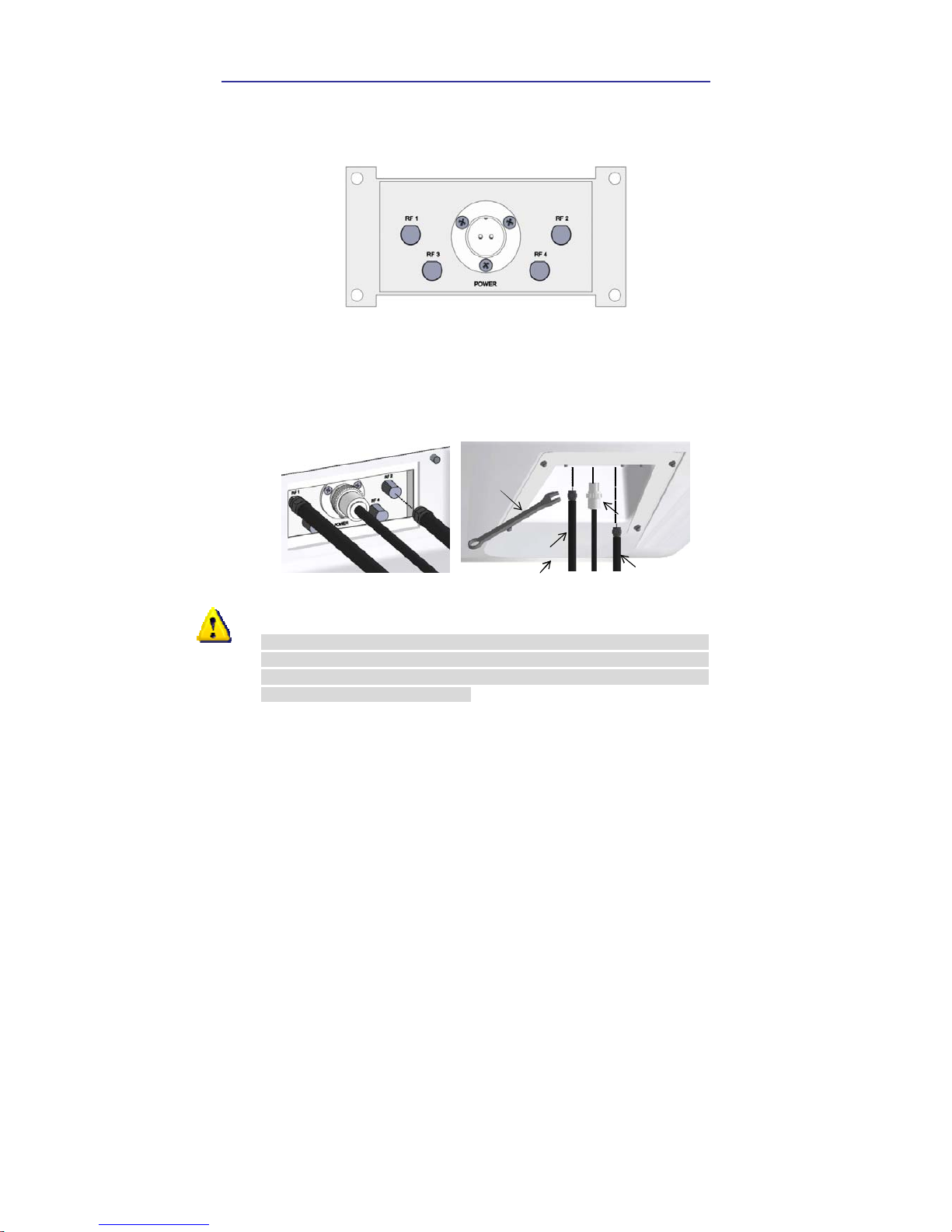
Connection of Power & SLC Cable
Bring the Power & SLC cable up through the access hole and connect it to
the base-plate. Figure below illustrates the connector assignments.
Connection of RF cable
Remove the rubber protector for RF cable connector RF1 at the bottom of the
antenna. Connect the RF Cable to the RF1 connector under the base plate
through the access hole using the 13mm spanner. Be careful not to tighten
too much, as you may damage the connector.
RF Cable
Optional
11mm Span ner
Power Cable
Antenna unit
Do not use excessive force when using the spanner to avoid damage of the
screw part. Be careful so that the connectors do not directly touch to the
mounting surface of the antenna, or it may cause a critical malfunction and/or
a serious damage to the equipment.
WARNINGWARNING

Installation 13
Fixation of the antenna
Fix the antenna to the holes made before as the drawing below by using the
hex head bolts (M8x50L), M8 spring washer, M8 flat washer and M8 nut
supplied.
Antenna Unit
M8 Flat Washer
13mm Spanner
13mm S panner
M8 Hex. Bolt
M8 Flat Washer
M8 Spring Washer
M8 Nut

14 i9/i9P Satellite Antenna System – Install and User Manual
Installing the ACU
ACU dimensions
5.38 (2.1”)
21.68(8.5”)
20.8 (8.2”)
22.8 (9”)
17.8 (7”)
5.5(2.2”)
13(5.1”)
18.5(7.3”)
Unit : c m (inch)
Selection of Installation Site
The ACU should be installed below decks, in a place of :
y Dry, cool, and ventilated.
y Easy accessible from your main TV viewing area.
.

Installation 15
To Install the ACU
1. The ACU should be installed using the two fixing brackets supplied to
provide a top or bottom fix.
2. Using the self tapping screws supplied fix the mounting brackets to the
sides of the ACU.
3. Place the ACU in the position where it is going to be installed.
4. Connect the cables to the rear of the ACU.
5. Using a pencil to mark the 4 hole positions (2 each side) for securing the
mounting brackets and using a suitable drill bit to drill them.

16 i9/i9P Satellite Antenna System – Install and User Manual
Connection of ACU and antenna
After installation and fixation of the antenna, connect the ACU to the antenna.
Referring to the drawing below, connect cables.
NMEA GPSDC Power Cable PC Cable
IRD2 (No t Supp lied)
TV (Not Supplied)
IRD1 (Not Supplied)
IRD3 (No t Supp lied)
IRD4 (No t Supp lied)
RF Cable
Power Cable
(Optional)
(Optional)
(Optional)
y Connect the Power & SLC Cable (30m) from the antenna to the
ANTENNA connector on the rear of the ACU.
y Connect the RF Cable (30m) from the RF connector on the antenna to
the rear of IRD.
y Connect the power cable (10m) from DC power connector on the rear of
ACU to a power source of DC (10.8~15.6V).
y Press the POWER ON switch in front of the ACU to start the operation of
the Antenna system automatically.

Installation 17
Connecting the system to a GPS
For improved satellite tracking, you can connect your satellite TV system
directly to your boat’s NMEA 0183 GPS system. To do this you will need two
cables which are suitable for connecting to your GPS system and the green
2-way ACU GPS connector supplied with your Intellian i9/i9P Satellite TV
System.
To connect the system to a GPS
1. Strip back the insulation of each cable and connect a cable to each
terminal of the 2-way connector.
2. Tighten the locking screws.
3. Connect the cable from the +ve terminal of the ACU GPS connector
to the NMEA OUT wire of the boat’s GPS system.
4. Connect the cable from the –ve terminal of the ACU GPS connector
to the ground wire of the boat’s GPS system.
5. Refit the ACU GPS connector to the rear of the ACU.
Ground (-)NMEA out (+)

18 i9/i9P Satellite Antenna System – Install and User Manual
Target Satellite Setting
You can select the target satellite to receive satellite signal. If the target
satellite is not on the list you have to register the target satellite.
GPS Setting
You can input the GPS information through the ACU or the PC Program. To
setting the GPS information, the antenna system has to be in ‘SET UP mode’.
For detailed instructions, please refer to page 37; ‘Setting the GPS’, and page
58; ‘Set Antenna GPS and find Antenna Angle’.
Satellite registration
You can register the target satellite through the ACU or the PC Program. To
register the target satellite, the antenna system has to be in ‘ SET UP mode’
and the required information are, Satellite name, Satellite Longitude, Method
of Satellite identification, Frequency of each of the Band, Symbol Rate,
Network ID, Power Change method. For detailed instructions, please refer to
page 30; ‘Edit Satellite Information’, page 52;‘ Set Satellite Information’, and
page 59; ‘Set Tracking Information of Satellite’.
Satellite Pair Selection
You can select the Satellite pair from the list through the ACU or the program.
You can easily select the target satellite from the satellite pair. For detailed
instructions please refer to page 28; ‘Setting the Satellite pair’, page 52; ‘Set
Satellite Information’.
Target Satellite Selection
Choose the target satellite from the Satellite Pair. When selecting through
the ACU, you have to press the left button to select the target satellite while
the antenna system is in either ‘Searching Mode’ or ‘Tracking Mode’. When
using the PC program you can select either satellite ‘A’ or satellite ‘B’ from
‘Tracking Satellite’ at anytime.

Installation 19
Adjusting the LNB Skew Angle (Linear polarization only)
Skew Angle Setting
The LNB feed horn skew angle has to be fixed at a specific position to receive
the maximized the satellite signal level. The skew angle is calculated with the
GPS data of the territory when registering the Satellite Pair. According to the
shift in longitude and latitude data the skew angle will adjust to the optimal
angle accordingly. When there is an error between the calculated skew angle
and the actual skew angle you can manually adjust the skew angle.
Adjustment of LNB Skew Angle
When you press the middle button of the ACU while the antenna system is in
‘Searching Mode’ or ‘Tracking Mode’, the elevation angle or the signal
strength will be shown. If you press the middle button one more time, the
current skew angle will appear. From this position when you press the right or
left button of the ACU, the LNB skew angle will move in CW or CCW direction
in one degree increments. Also, you can move the LNB skew angle in CW or
CCW direction by one degree increments from the ‘Set LNB Skew’ menu
when the antenna is in ‘SET UP Mode’. Refer page 61; ‘Selection of LNB
Skew Angle’. If you don’t know the exact LNB skew angle, adjust the angle by
finding position where the satellite signal strength is at the maximum level.
When the LNB skew angle is adjusted manually, the antenna system stores
this information until you reset the satellite pair information. When selecting
the target satellite, the skew motor automatically sets the optimal skew angle
for the antenna system to track the target satellite.
In case of LNB turning mechanism available
The skew drive mechanism is consisted of the rotational feed horn, skew
motor and LNB. Skew angle may be adjusted manually to the target angle
through ACU and GUI Program. The current skew angle will be indicated
through the ACU and GUI program.
Intellian i9/i9P with GPS sensor is built in, manual adjustment of skew angle
by user is not required. The skew angle is continuously adjusted
automatically through the calculation of the optimum skew angle by using the
information of the targeted satellite and the output value from the GPS sensor.
Together with such location information of the ship as ship’s longitudinal and
latitudinal position change from movement the skew angle will be adjusted
accordingly. The skew angle of LNB is shown by ACU and GUI Program.

20 i9/i9P Satellite Antenna System – Install and User Manual
Skew Motor
Skew sens or
LNB

Operation Instruction 21
Operation Instruction
Introduction
This section of the handbook describes how to set up your Satellite TV System
after installation using the ACU or PC controller program and includes the
following functions:
System start up.
Changing the default satellite.
Monitoring the antenna status.
Setting sleep mode.
Entering setup mode.
Setting the satellite pair.
Editing satellite information.
Setting the antenna parameter.
Setting the LNB local frequency.
Setting GPS.
Setting the DiSEqC method.
Display versions.
Display power status.
Setting antenna go position.
Setting antenna move step.
Setting remote control.
Setting the factory default parameters.
Performing diagnostic tests.
Note: Many of the above functions will only be required at initial installation of your
system.

22 i9/i9P Satellite Antenna System – Install and User Manual
Operation Using the ACU
ACU Soft Keys
BACK
ENTER
POWER
Press to select
On-sc reen optio n
Normal Mode
Start Up
With the system installed and power applied, the ACU screen will show the
following sequence:
INITIALIZE ACU
INTELLIAN I9
SEARCH A: DTV101
B:DTV119 SETUP
1.Commu nication is being established between the
antenna and the ACU. The ACU initialized.
INITIALIZE ANTENNA
INTELLIAN I9
TRACKING A:DTV101
B:DTV119 SETUP
2. The antenn a is initialized.
3. The antenn a is searchi ng for Satellite A.
4. Th e anten na has locate d the satell ite an d i s n ow
trackin g.

Operation Using the ACU 23
Initial Setup
Start Up
With the system installed and power applied, the ACU screen will show the
following sequence:
Change of Target Satellite
Your antenna is programmed with two candidates of target satellites as
default Dual-sat mode. Use advanced Triple-sat mode for targeting three
satellites. To change the target satellite, press LEFT soft key. The target
satellite is changed and is automatically tracked by the antenna.
Default Dual-sat Mode
TRACKING A:DTV101
B:DTV119 SETUP
TRACKING B:DTV119
A:DTV101 SETUP
2. The antenna is tracking Satellite B.
1. Press LEFT soft key for tracking Satellite B.

24 i9/i9P Satellite Antenna System – Install and User Manual
Advanced Triple-sat Mode
TRACKING A: DTV101
DTV119 DTV110#
TRACKING B: DTV119
DTV110# DTV101
* Register a key on your remote control to track alternative target satellites.
See
pag
e 43.
TRACKING A:DTV101
B:DTV119 SETUP
TRACKING B: DTV119
DTV110# DTV101
TRACKING B: DTV119
DTV110# DTV101
TRACKING C: DTV110#
DTV101 DTV119
TRACKING B: DTV119
DTV110# DTV101
2. Th e an ten na i s track ing Satel lite B.
1. Press LFET soft key for tracking Satellite B.
3. Press LFET soft key for tracking Satellite C.
4. The antenna is tracking Satellite C.

Operation Using the ACU 25
Monitoring the current status of the antenna
While POWER ON to Intellian i9/i9P, ACU displays the status of the antenna.
The various ACU displays may be shown according to the current status of
the antenna.
ANTENNA IS UNWRAPING
B:DTV119 SETUP
SEARCH A: DTV101
B:DTV119 SETUP
TRACKING A:DTV101
B:DTV119 SETUP
AZ : ###.# EL : ##.#
SIGNAL:###● [VL]
TRACKING A:DTV101
B:DTV119 SETUP
###.##E ##.##N
SETUP
1. The antenna is searchin g for Satellite A.
2. The antenn a is tracking Satelli te A.
3. The antenn a is un wrapping the cabl e.
4. The antenn a is again tracking satelli te A.
Press center soft key to di splay position detail.
5. Antenn a position detail and si gnal strength are
displayed.
6. Press center soft key to display current GPS
inf ormation. Press SETUP to return to main setup
mode.

26 i9/i9P Satellite Antenna System – Install and User Manual
Sleep Mode
If the antenna lost the tracking satellite in sleep mode, sleep mode is
cancelled.
* Register a key on your remote con trol to ch ange sleep mode.
See page 43.
TRACKING :A:DTV101
B:DTV119 SETUP
TRACKING :A:DTV119
¦B:DTV119 SETUP
1. Press BACK to enter sleep mode.
2. Press Back again for exiting sleep mode.

Operation Using the ACU 27
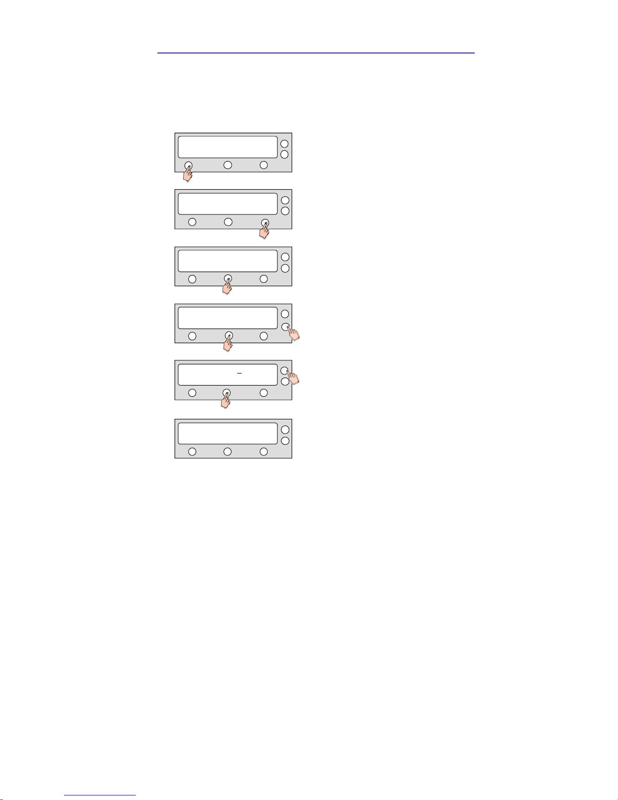
Set Up Mode
Begin Set-Up Mode
To start setting various information and settings for your Intellian i9/i9P simply
follow the instructions below.
SETUP MODE?
YES NO
TRACKING A:DTV101
B:DTV119 SETUP
SET SAT PAIR ?
PREV YES NEXT
1. With the ante nn a tracki ng .
Press SETUP.
2. Press YES to enter setup mode.
3. Press Yes to set the satellite pair.

28 i9/i9P Satellite Antenna System – Install and User Manual
Setting the Satellite Pair
You can change the satellite pair if you decide to receive satellite television
service from a different service provider.
CASE 1. DiSEqC is not used for changing target satellite.
SETUP MODE?
YES NO
SET SAT PAIR ?
PREV YES NEXT
SAT A : D TV101
PREV SELECT NEXT
SAT B : D TV119
PREV SELECT NEXT
SAVE ?
YES NO
1. Press YES to enter setup mode.
2. Pre ss Y ES to set s atellite pai r.
SET TRIPLE SAT ?
YES NO
3. Press YES to set triple satelli te.
SAT C: DTV110#
PREV SELECT NEXT
4. Set satellite A
Press PR EV to sh ow previous satellite n ame.
Press SELECT to set chosen satellite to SAT A.
Press NEXT to show next satellite n ame.
5. Set satellite B
Press PR EV to sh ow previous satellite n ame.
Press SELECT to set chosen satellite to SAT B.
Press NEXT to show next satellite n ame.
7. Press YES to save selection s.
Pres s NO to cancel and return to m ain setup m ode.
6. Set satellite C
Press PR EV to sh ow previous satellite n ame.
Press SELEC T to set ch osen satell ite to SAT C.
Press NEXT to show next satellite name.

Operation Using the ACU 29
CASE 2. DiSEqC is used for changing of target satellite.
SETUP MODE?
YES NO
SET SAT PAIR ?
PREV YES NEXT
SAT A : D TV101
PREV SELECT NEXT
SAT B : DT V119
PREV SELECT NEXT
SAVE ?
YES NO
SAT A* : DTV101
PREV SELECT NEXT
SAT B* : DTV119
PREV SELECT NEXT
1. Press YES to enter setup mode.
2. Press YES to set satellite pair.
7. Press YES to save selections.
Press NO to cancel and retu rn to main setup mode.
3. Set satellite A
Press PREV to show previous satellite name.
Press SELECT to set chosen satellite to SAT A.
Press NEXT to show next satellite name.
4. Set satellite B
Press PREV to show previous satellite name.
Press SELECT to set chosen satellite to SAT B.
Press NEXT to sh ow next satellite name.
5. Set satellite A* when DiSEqC is active from IRD.
Press PREV to show previous satellite name.
Press SELECT to set chosen satellite to SAT A*.
Press NEXT to show next satellite name.
6. Set satellite B* wh en DiSEqC is active from IRD.
Press PREV to show previous satellite name.
Press SELECT to set chosen satellite to SAT B*.
Press NEXT to show next satellite name.

30 i9/i9P Satellite Antenna System – Install and User Manual
Edit Satellite information
It is possible to modify the existing satellite information and input new
satellite information from ACU as well. It is not recommended for a novice at
satellite service to use this mode.
SETUP MODE?
YES NO
SET SAT PAIR ?
PREV YES NEXT
SAT NAME : DTV101
PREV SELECT NEXT
x2
EDIT SAT INFO ?
PREV YES NEXT
SAT NAME : DTV101
- INPUT +
SAT NAME : DTV101
- INPUT +
LONGITUDE 124.00 E
- INPUT +
1. Press YES to enter setup mode.
2. Press NEXT twice to enter edit satellite info mode.
3. Press YES to edit satellite info.
4. Set the satellite name.
PREV – Sh ows previous satellite name.
SELECT – Select the displayed satellite for editing.
NEXT – Sh ows next satellite name.
Press ENTER to move to next screen.
5. Input the satellite name.
+ Increases the value. - decreases the value.
Change the underscored digit using the +/- buttons.
Press INPUT to accept the value and move to next
digit. Press BACK to m ove to previous digit.
6. Press ENTER to move to next screen.
Press BACK to return previou s screen.
7. Input the satellite position.
+increases a value. – decreases a value.
Chan ge the un derscored digit usin g the +/- bu ttons.
Press INPUT to accept the value and move to next
digit. Press BACK to move to previous digit.

Operation Using the ACU 31
HOR LOW 12523 21096
- INPUT +
HOR LOW NID 0x0003
- INPUT +
VER HIGH 12598 21096
- INPUT +
VER HIGH NID 0x0003
- INPUT +
VER LOW 12598 21096
- INPUT +
VER LOW NID 0x0003
- INPUT +
HOR HIGH 12523 21096
- INPUT +
10. Inpu t the tracking frequency (MHz) and symbol
rate (KH z) for h orizon tal low ban d.
11. Input th e netw ork ID (N ID) for horizontal low band .
12. Inpu t the tracking frequency (MHz) and symbol
rate (KH z) for verti cal h igh band.
13. Input the network ID (NID) for vertical high band.
8. Inpu t the tracking frequency (MHz) and symbol
rate (KH z) for verti cal low band.
9. In pu t th e n etwork ID (NID) for verti cal low band.
14. Inpu t the tracking frequency (MHz) and symbol
rate (KH z) for h orizon tal high band.

32 i9/i9P Satellite Antenna System – Install and User Manual
SAVE ?
YES NO
19. P ress YE S to save th e inpu t in form ati on.
Press NO to canc el an d retu rn to mai n s etup
mode.
VERIFY : DVB DECODE
PREV SELECT NEXT
VOLTAGE: AUTO
PREV SELECT NEXT
16. Select the verification method
1)
of tracking
satellite.
PREV – Shows previous method.
SELECT – Set th e displayed m ethod.
NEXT – Shows next method.
DISEQC: ONLY 22KHZ
PREV SELECT NEXT
18. Select the D ISEQC m eth od
3)
(AUTO recom men ded)
1) Verification method
SIGNAL – use on ly signal level for tracking
DVB LOCK – u se only DVB Lock sign al for tracking
DVB DECODE – verify satellite using DVB decoding method for tracking
DSS DE CODE – decode on ly DSS Lock si gnal for tracking
2) Voltage supply method
AUTO- chan ge voltage to LNB by IRD voltage
ONLY 13V – al ways supply 13V to LNB
ONLY 18V – al ways supply 18V to LNB
3) DISEQC method
AUTO – ch ange sign al to LNB by IRD DISEQC
ONLY 0KHZ – al ways supply 0kHz to LNB
ONLY 22KHZ - al ways supply 22kHz to LNB
HOR HIGH NID 0x0003
- INPUT +
15. Inpu t th e netw ork ID (N ID) for hori zonta l h igh
band.
17. Select the voltage supplymethod
2)
to LN B
(AUTO recom men ded )

Operation Using the ACU 33
Setting the Antenna Parameters
It is not recommended for a novice at satellite service to use this mode.
Consult Intellian for changing antenna parameters.
SETUP MODE?
YES NO
SET SAT PAIR ?
PREV YES NEXT
PARAM: SCAN OFF
PREV YES NEXT
x3
SET ANT PARAMETER?
PREV YES NEXT
WRS LEVEL : 0500
- INPUT +
SATNAME : DTV101
- INPUT +
SAVE ?
YES NO
1. Press YES to e n ter setu p m od e.
4. Select th e PARAM
1)
– SCAN OFF
PREV – Shows previous parameter.
SELECT – Set the displayed parameter.
NEXT – Shows next parameter.
Press ENTER to move to next screen.
5. Input the WRS LEVEL.
+increases the value. – decreases the value.
Change the underscored digit using the +/- buttons.
Press INPUT to accept the value and move to next
digit. Press BACK to m ove to pre viou s digit.
Press ENTER to m ove to next screen.
6. Press YES to save the in put information.
Press NO to cancel and retu rn to ma in setup m ode.
2. Press NEXT th ree tim es to enter set anten n a
parameter mode.
3. Press YES to set antenna parameter.

34 i9/i9P Satellite Antenna System – Install and User Manual
1) Parameter Settin g meth od
SCAN OFFSET – The actual angle between the marked poin t on
the sub-reflector and the datum .
TRACK SCALE – To control the trackin g speed while antenna is tracking
the satellite. High Track Scal e value resu ltin g in high tracking speed.
DETECT LEVEL – The basic single detection level.
TRACKING LEVEL – The basic signal tracking l evel
EL ADJUST – The mechani cal tolerance compensation of elevation limit.
WRS LEVEL – The basic WRS detection level.
POWER THRESHOLD – The value to iden tify Vertical/Horizontal or
RHCP/LHCP.
DISEQC LEVEL – The value to identify 22KHz tone.
OFFSET RH-LH – The differen ce valu e between R HCP/LHCP and
SCAN OFFSET.
USE WRS – To apply WRS w hile antenna is searchi ng for satellite.
OFFSET DIFFEREN CE – To apply Offset Difference.
Operation Using the ACU 35
Setting the LNB local frequency
It is possible to select a local frequency from ACU. It is not recommended for
a novice at satellite service to use this mode.
CASE 1. Single band LNB is used.
SETUP MODE?
YES NO
SET SAT PAIR ?
PREV YES NEXT
SAVE ?
YES NO
x4
SET LOCAL FREQ?
PREV YES NEXT
LOCAL FREQ: #####MHz
- INPUT +
LNB TYPE : SINGLE
PREV SELECT NEXT
1. Press YES to enter setup mode.
2. Press N EXT fou r times to en ter set local frequ en cy
mode.
3. Press YES to set local frequency.
4. Select the LNB Type
1)
–SINGLE.
PREV – Shows previous LNB type.
SELECT – Set the displayed LNB type.
NEXT – Shows next LNB type.
Press ENTER to m ove to next screen.
5. Inpu t the l ocal f requ ency of LNB.
+increases the value. – decreases the value.
Change the un derscored digit usin g the +/-
bu tton s. Press INPU T to accept th e valu e an d
move to n ext digit. Press BACK to mo ve to
previous di git. Press EN TER to move to n ext
screen.
6. Press YES to accept the data.
Press NO to cancel and retu rn to main setu p m ode.

36 i9/i9P Satellite Antenna System – Install and User Manual
CASE 2. Universal LNB is used. (Low band local frequency-9750 MHz/ High
bnad local frequcny 10600 MHz)
1) LNB Type
SINGLE: Single Band LNB
Asia 11300 MHz, Japan 10678MHz, Korea 10750MHz, America 11250MHz
UNIVERSAL : Universal LNB
Low ban d local frequency -9750 MHz
High band l ocal frequen cy -10600 MHz
SETUP MODE?
YES NO
SET SAT PAIR ?
PREV YES NEXT
SAVE ?
YES NO
x4
SET LOCAL FREQ?
PREV YES NEXT
LNB TYPE : UNIVERSAL
PREV SELECT NEXT
1. Press YES to enter setup mode.
2. Press NEXT fou r ti mes to en ter set local
frequen cy mode.
3. Press YES to set local frequen cy.
4. Select the LNB Type
1)
– UNIVERSAL.
PREV – Sh ows previous LNB type.
SELECT – Set the displayed LNB type.
NEXT – Sh ows next LNB type.
Press ENTER to move to next screen.
5. Press YES to accept the data.
Press N O to cancel and return to main setup m ode.

Operation Using the ACU 37
Setting the GPS
It is possible to set up and modify the GPS information, which enhance the
antenna function.
SETUP MODE?
YES NO
SET SAT PAIR ?
PREV YES NEXT
LONGITUDE ###.## E
- INPUT +
x1
SET GPS ?
PREV YES NEXT
LATITUDE ##.## N
- INPUT +
LONGITUDE ###.## E
- INPUT +
SAVE ?
YES NO
1. Press YES to enter setup mode.
2. Press NEXT to enter GPS setup mode.
3. Press YES to set GPS.
4. Inpu t the lon gitude data.
+increases the value. – decreases the valu e.
Change the underscored digit using the +/- buttons.
Press INPUT to accept the valu e and move to n ext
digit. Press BACK to move to previous digit.
6. Inpu t the latitude data.
+increases the value. – decreases the valu e.
Chan ge the un derscored digit usin g the +/- buttons.
Press INPUT to accept the value and m ove to next
digit. Press Back to move to previous digit.
5. Press ENTER to move to next screen.
Press BACK to move to previous screen.
7. Press YES to accept data.
Pres s NO to cance l an d retu rn to main setup mode.

38 i9/i9P Satellite Antenna System – Install and User Manual
Setting the DiSEqC Method
DiSEqC selection is made at ACU. It is not recommended for a novice at
satellite service to use this mode.
SETUP MODE?
YES NO
SET SAT PAIR ?
PREV YES NEXT
SAVE ?
YES NO
x5
USE DISEQC ?
PREV YES NEXT
DO NOT US E DISEQC
PREV SELECT NEXT
1) DiSEqC Method
DO NOT USE DISEQC – DiSEqC is not using.
USE TO CH ANGE BAND – DiSEqC is u sing to change to low and h igh band.
USE TO CHANGE SAT – DiSEqC is using to change tracking satellite
1. Press YES to enter setup mode.
2. Press NEXT five times to enter DISEQC mode.
3. Press YES to use DISEQC.
4. Select the DiSEqC Method
1)
PREV – Sh ows previous DiSEqC Method.
SELECT/ENTER – Set the displayed DiSEqC
method.
NEXT– Shows next DiSEqC Method.
Press ENTER to move to next screen.
5. Press YES to accept the selection.
Press N O to cancel and return to m ain setup m ode.

Operation Using the ACU 39
Display Versions
This sequence enables you to see what version of antenna and ACU
software version are installed in your system.
SETUP MODE?
YES NO
SET SAT PAIR ?
PREV YES NEXT
x6
VIEW VERSION ?
PREV YES NEXT
ANT S/W VER : 4.00
S/N: 0000000000 EXIT
ACU S/W VER : 0.01
S/N: 0000000000 EXIT
SF-901S
S/N: 0000000000 EXIT
1. Press YES to enter setup mode.
2. Press NEXT six times to enter the view version
mode.
3. Press YES to view version.
5. Antenna software version an d S/N are shown .
Press center soft key to view ACU software
version. Press EXIT to return to main setup mode.
6. ACU software version and S/N are shown.
Press EXIT to return to main setup mode.
4. Antenna produ ct nam e and S/N are shown .
Press center soft key to view antenna software
version. Press EXIT to return to main setup mode.

40 i9/i9P Satellite Antenna System – Install and User Manual
Display Power
SETUP MODE?
YES NO
SET SAT PAIR ?
PREV YES NEXT
x7
VIEW POWER ?
PREV YES NEXT
ANT POWER : 22.9 V
EXIT
IRD : 18V + ##kHz
EXIT
1. Press YES to enter setup mode.
ACU POWER : 24.1 V
EXIT
2. Press NEXT seven times to enter the view power
mode.
3. Press YES to view power.
5. Antenn a Voltage is sh own.
Press center soft key to view IRD Voltage and
frequen cy. Press EXIT to return to main setup
mode.
6. IRD Voltage and frequen cy are shown.
Press EXIT to return to main setup mode.
4. ACU Voltage is shown.
Press center soft key to view antenna voltage.
Press EXIT to return to main setup m ode.

Operation Using the ACU 41
Setting Antenna Go Position
The antenna can be controlled manually by using ACU.
SETUP MODE?
YES NO
SET SAT PAIR ?
PREV YES NEXT
GOTO POSITION ?
YES NO
x9
ANT GO POSITION?
PREV YES NEXT
GO TO AZ : ###.#
- INPUT +
GO TO EL : ###.#
- INPUT +
AZ:###.# EL:###.#
EXIT
1. Press YES to enter setup mode.
2. Press NEXT nine times to enter the antenn a go
position mode.
3. Press YES to go position.
4. Input position value for azimu th (AZ) axis.
+ increases the valu e. – decreases th e value.
Change the underscored digit using the +/- buttons.
Press INPUT to accept the valu e and move to next
digit. Press BACK to move to previous digit.
Press ENTER to move to n ext screen.
6. Press YES to move the antenna to input position.
Press NO to re turn to the An tenn a Go P osition
mode.
7. Press EXIT to return to m ai n setu p mode.
5. Input position value for elevation (EL) axis.
+ increases the valu e. – decreases th e value.
Change the underscored digit using the +/- buttons.
Press INPUT to accept the valu e and move to next
digit. Press BACK to move to previous digit.
Press ENTER to move to n ext screen.

42 i9/i9P Satellite Antenna System – Install and User Manual
Setting Antenna Move Step
The antenna may be moved by 1° step manually by using ACU.
SETUP MODE?
YES NO
SET SAT PAIR ?
PREV YES NEXT
x10
ANT MOVE STEP ?
PREV YES NEXT
STEP AZ : ###.#
CCW EL CW
STEP EL : ##.#
DOWN EXIT UP
1. Press YES to enter setup mode.
4. Move the an tenna in the azimuth (AZ) axis.
CW – Move the antenna clockwise.
CCW – Move the antenna coun ter-clockwise.
EL – Go to elevation control screen.
5. Move the antenn a in the elevation (EL) axis.
UP – Move the antenna up.
DOWN – Move the antenna down.
EXIT – Return to Antenn a Move Step m ode.
2. Press NEXT ten tim es to en ter the an tenna
move step mode.
3. Press YES to move step.

Operation Using the ACU 43
Setting Remote Control
SETUP MODE?
YES NO
SET SAT PAIR ?
PREV YES NEXT
x8
SET REMOCON ?
PREV YES NEXT
FUNC : CHANGE SAT
NEXT SELECT EXIT
PRESS A REMOTE KEY
BACK EXIT
FUNC : SLEEP MODE
NEXT SELECT EXIT
1. Press YES to enter setup mode.
2. Press NEXT eight times to en ter remote control
settin g mode .
3. Press YES to set remote control.
4. Select the Function
1)
NEXT – Shows next function.
6. Poin t remote con trol to ACU .
Press any key on remote control for sel ected
fun ction and press same key again f or
confi rmation.
Press BACK to move to previous screen.
Press EXIT to return to main setup mode.
5. SELECT/ENTER –Registers a key on remote
control .

44 i9/i9P Satellite Antenna System – Install and User Manual
REMOTE KEY REGISTED
1) Function
CHANGE SAT Change the target satellite.
SLEEP MODE Enter sleep mode.
CLEAR REGISTERED KEY Clear registered key.
THAT KEY IS USING
FUNC : CHANGE SAT
NEXT SELECT EXIT
FAILED - TRY AGAIN
8. If failed to register a free key, KEY IS USING will
be displayed.
9. REMOTE KEY REGISTED will be displayed if key
has been properly registered.
10. Press NEXT to sh ows next function.
Press EXIT to return to main setup mode.
7. If failed to press same key twice, TRY AGAIN will
be displayed.

Operation Using the ACU 45
Executing Antenna Diagnosis
It is possible to see the antenna status by reviewing the result of diagnosis of
the antenna. Refer to the following codes, to understand the diagnosis
results.
SETUP MODE?
YES NO
SET SAT PAIR ?
PREV YES NEXT
x11
ANT DIAGNOSIS ?
PREV YES NEXT
CODE 101 TESTING.
RESULT: ? EXIT
CODE 101 PASSED.
RESULT: 1 EXIT
1. Press YES to enter setup mode.
2. Press NEXT eleven times to enter the an tenn a
diagnosis mode.
3. Press YES to diagn osis antenn a.
4. CODE 101 is being tested.
Press EXIT to return to main setup mode.
5. CODE
1)
101 is pass.
Press EXIT to return to main setup mode.

46 i9/i9P Satellite Antenna System – Install and User Manual
CODE 101 : Commu nication between an tenna and antenna control u nit is tested.
If fai led, check the power and data cabl e.
CODE 102 : AZ CW limit is tested.
If failed, check the limit sensors, motor ,and belt for AZ axis.
CODE 103 : AZ CCW limit is tested.
If failed, check the limit sensors, motor ,and belt for AZ axis.
CODE 104 : EL axis is tested.
If failed, check the limit sensors, motor ,and belt for EL axis.
CODE 105 : S ub-reflector is tested.
If failed, check the sub-reflector.
CODE 106 : LNB is tested.
If failed, check the LNB and con trol board.
CODE 107: Skew System tested.
If failed, check the control board, skew motor ,and skew sen sor
CODE 108 : Antenna Input Power tested.
If failed, check the RF cable.
CODE 109 : ACU Power tested.
If fai led, check the ACU power cable and In put DC power.
CODE 110 : IRD Power tested.
If failed, check the ACU to IRD cable an d IRD power.
RESULT STATUS : ● is pass. Number is fail(●● 3 ●● ●● 8 ●●). And ? Is Testin g.

Operation Using the ACU 47
Setting Region
SETUP MODE?
YES NO
SET SAT PAI R ?
PREV YES NEXT
x12
LOAD REGION INFO?
PREV YES NEXT
CONTINENT: EUROPE
PREV SELECT NEXT
LOAD?
YES NO
1. Press YES to enter setup mode.
2. Press NEXT twelve times to enter the load region
inf ormation mode.
3. Press YES to load region information.
4. Select th e con tinent
1)
.
PREV – Shows previous contin ent.
SELECT– Select the displayed continent for editing.
NEXT – Sh ows next contin ent.
6. Press YES to accept the selection.
Pres s NO to can cel and return to m ain setu p mode
LOADING : ?
ٛ
DO NOT TURN OFF!
7. After loading, au to restart.
REGION : ITALY
PREV SELECT NEXT
5. Select the region2).
PREV – Shows previous region .
SELECT– Select the displayed region for editing.
NEXT – Shows next region .
1) CONTINENT
EUROPE, N AMERICA, S AMERICA, ASIA, OCEANIA, AFRICA
2) REGION
UK, KOR, USA-1, USA-2 ,JAPAN? .

48 i9/i9P Satellite Antenna System – Install and User Manual
Setting the factory default parameters
Initialize all of the antenna information to the factory set up.
SETUP MODE?
YES NO
SET SAT PAIR ?
PREV YES NEXT
x13
SET DEFAULT ?
PREV YES NEXT
1. Press YES to enter setup mode.
2. Press NEXT thirteen times to enter the default
setting mode.
3. Press YES to set default parameters.

Operation Using PC Controller Program 49
OPERATION USING PC Controller Program
Introduction
GUI Software of Intellian i9/i9P has been coded for the user to easily set up the
antenna by using the user’s personal computer. Using the GUI program
enables the user to easily monitor and modify the information of antenna,
satellite and GPS. Additionally, the detail diagnostic method of the antenna is
provided by the GUI program.
To start this GUI program,
1. Connect one end of PC serial cable to the serial port on the computer.
2. Connect the other end of the PC serial cable to the “PC Interface” on
the rear of ACU.
3. Execute GUI program by inserting the CD-ROM supplied into the
CD-ROM drive of the computer.
4. After turning on the power of the ACU, if the blue status circle does not
change to ‘Search’ or ‘Tracking’ from ‘Initialize’, then you have to
change the “PC Interface” terminal of ACU for PC program use rather
than GPS use.

50 i9/i9P Satellite Antenna System – Install and User Manual
Program Initialing and Serial Port Setup
The communication between the ACU and antenna must be established as the
first step in order to start setting your antenna.
Serial port setting
Connect /Disc onnect
Button
Com municati on stat us
display
Baudrate setting
Command Button
y Baud Rate Setting – To display communication speed.
y Connection Status Display – To display communication port
between ACU and PC.
y Serial Port Setting – To select serial port to be used.
y Connect/ Disconnect – To establish communication between
PC and ACU.
Operation Using PC Controller Program 51
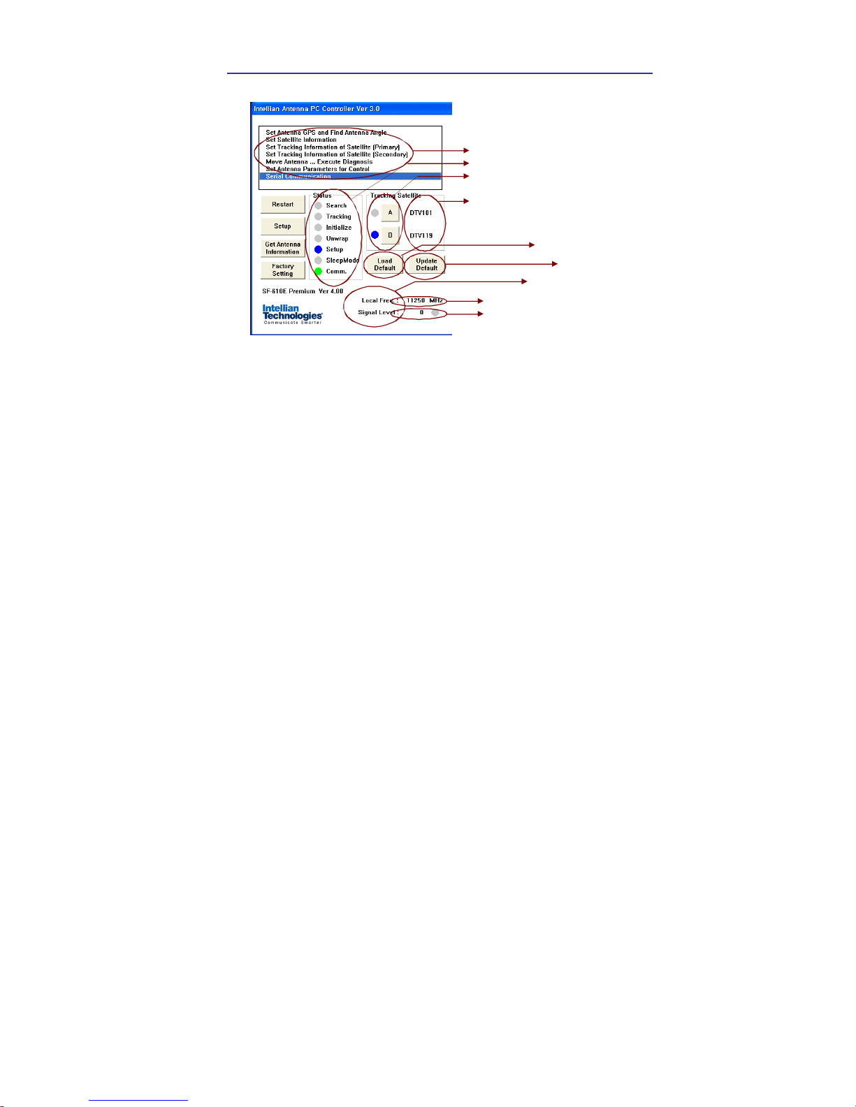
Main Menu – Using Default Dual-sat Mode
Loc al frequency
Sig nal streng th
Antenna s tat us moni to ring
Select & Monitor target satellite
Satellite pair
DTV101 – SAT A without DiS Eq C
DTV119 – SAT B without DiS Eq C
Controll er Menu
Load Defaul t
1)
Upd ate Def ault
2)
Antenna Status Monitoring
y Search – Antenna is searching for the selected satellite.
y Tracking – Antenna is tracking the selected satellite.
y Initialize – Antenna or the ACU is initializing.
y Unwrap – Antenna is unwrapping the wire.
y Setup – Antenna is in setup mode.
y Comm. – Antenna is possible communication.
Definition of program Command Buttons
y Restart – To exit setup mode and restart antenna again.
y Setup – To enter the setup mode.
y Get Antenna Information – To indicate the information on
display after receiving it input to the antenna.
y Factory Setting – To initialize all antenna information to the
default ex-factory status.
y Load Default – To display the up-to-date information from the
PC program.
y Update Default – To update the antenna information by the
up-to-date information from the PC program.

52 i9/i9P Satellite Antenna System – Install and User Manual
Set Satellite Information
DiSEqC using method
Satellite Verification method
Register satellite for tracking
Select LNB type
Set loc al freq uency of LNB
[XY Z
Satellit e name and lo ngitude
Select Triple Satellite
y Satellite Information
The name, longitude and confirmation method of the satellite is
displayed when a satellite is selected in the list box. Push “Edit
Satellite Information” button to update the information on
modifying the value.
y DiSEqC
When the operation method of DiSEqC is selected to “Change
Band”, DiSEqC may be used for updating the local frequency
and to “Change Satellite”, for updating the target satellite.
y Registration of target satellite
In case that the DiSEqC is selected to “Not Use” or “Change
Band”, only X“Register for Sat A” and Y“Register for Sat B”
may be registered. Pushing X or Y button after selecting the
satellite in the list box makes it possible to register A or B. In
case that DiSEqC is selected to “Change Satellite”, Z“Register
for Sat A” and [“Register for Sat B” are activated and the
target satellite when DiSEqC is available may be registered by
pushing Z and [ buttons.
y Local Frequency
In case that DiSEqC is selected to “Change Band”, be sure to
push the “Universal LNB” button. In case that the DiSEqC is
selected to “Not Use” or “Change Satellite”, be sure to push
“Single Band” button and key in into the Local Frequency, and
then push “ Set Local Frequency” button.

Operation Using PC Controller Program 53
Command Button
y Edit Satellite Information – To modify the satellite information.
y Register for Sat A – To register a satellite to satellite A.
y Register for Sat B – To register a satellite to satellite B.
y Not Use – Do not use DiSEqC.
y Change Band – To use DiSEqC to change band.
y Change Satellite – To use DiSEqC to change the satellite.
y Singe Band – Antenna in use of Single LNB.
y Universal Band – Antenna in use of universal LNB.
y Set Local Frequency – To select local frequency of LNB.

54 i9/i9P Satellite Antenna System – Install and User Manual
Main Menu- Using Advanced Triple-sat Mode
Loc al f requency
Signal strength
Antenna s tat us moni to ring
Select & Monitor target satellite
Satellite pair
DTV101 – SAT A without DiSEqC
DTV119 – SAT B without DiSEqC
DTV110# – SAT C with DiSEqC
Cont roller Menu
Load Default
1)
Update Default
2)
Antenna Status Monitoring
y Search – Antenna is searching for the selected satellite.
y Tracking – Antenna is tracking the selected satellite.
y Initialize – Antenna or the ACU is initializing.
y Unwrap – Antenna is unwrapping the wire.
y Setup – Antenna is in setup mode.
y Comm. – Antenna is possible communication.
Definition of program Command Buttons
y Restart – To exit setup mode and restart antenna again.
y Setup – To enter the setup mode.
y Get Antenna Information – To indicate the information on
display after receiving it input to the antenna.
y Factory Setting – To initialize all antenna information to the
default ex-factory status.
y Load Default – To display the up-to-date information from the
PC program.
y Update Default – To update the antenna information by the
up-to-date information from the PC program.

Operation Using PC Controller Program 55
Set Satellite Information
DiSEqC using method
Satellite Verification method
Regis ter satellit e fo r tracking
Select LNB type
Set lo cal freq uency o f LNB
XY Z
Satellite nam e and longitud e
Select Triple S atellite
y Satellite Information
The name, longitude and confirmation method of the satellite is
displayed when a satellite is selected in the list box. Push “Edit
Satellite Information” button to update the information on
modifying the value.
y DiSEqC
When the operation method of DiSEqC is selected to “Change
Band”, DiSEqC may be used for updating the local frequency
and to “Change Satellite”, for updating the target satellite.
y Registration of target satellite
In case that Triple Satellite Mode is selected and the DiSEqC
is selected to “Not Use, only X“Register for Sat A”, Y“Register
for Sat B” and Z “Register for Sat C” may be registered.
Pushing X or Y or Zbutton after selecting the satellite in the
list box makes it possible to register A or B or C.
y Local Frequency
In case that DiSEqC is selected to “Change Band”, be sure to
push the “Universal LNB” button. In case that the DiSEqC is
selected to “Not Use” or “Change Satellite”, be sure to push “Si
ngle Band” button and key in into the Local Frequency, and
then push “ Set Local Frequency” button.

56 i9/i9P Satellite Antenna System – Install and User Manual
Command Button
y Edit Satellite Information – To modify the satellite information.
y Triple Satellite Mode – To use Triple Satellite.
y Register for Sat A – To register a satellite to satellite A.
y Register for Sat B – To register a satellite to satellite B.
y Register for Sat C – To register a satellite to satellite C.
y Not Use – Do not use DiSEqC.
y Change Band – To use DiSEqC to change band.
y Change Satellite – To use DiSEqC to change the satellite.
y Singe Band – Antenna in use of Single LNB.
y Universal Band – Antenna in use of universal LNB.
y Set Local Frequency – To select local frequency of LNB.
Load and Update Default Command Button
1) Load Default: Click “load default” button to select *.rif file according
to your region.

Operation Using PC Controller Program 57
2) Update Default: Click “Update default” button to open update default
Dialogue. Click “yes” button to update the system.
3) Click “confirm / yes” button to complete the update.

58 i9/i9P Satellite Antenna System – Install and User Manual
Controller menu
Set Antenna GPS and Find Antenna Angle
Antenna makes use of GPS information to search satellite quickly.
The more precise the GPS information is, the quicker the antenna is able
to search the satellite. The method to input information into GPS is to
push “Set GPS” button after keying in the latitude and longitude
information on “City GPS”. Pushing “Add City” button stores the GPS
information. By selecting the stored region in the list box, the GPS
information of such region is displayed. The Intellian i9/i9P satellite TV
antenna system utilizes GPS data to locate the satellite faster.
Command Buttons
Load GPS Files – Reads in the various city information from the GPS
files.
Add City – Adds the name of city and its GPS information to GPS files.
Delete City – Deletes the name of city and its GPS information from the
GPS files.
Set GPS – Inputs the indicated GPS information on display to antenna.
Find Angles & Skew Antenna GPS – Finds the current antenna angles
and Skew angle in relation to the longitude of satellite and GPS.
Find Angles & Skew City GPS – Finds the current city angles and Skew
angle in relation to the latitude of satellite and GPS.
Po sition st ored in Antenna
Calculated Angl e
Satellit e Longitud e
City GP S data
GPS Mess age

Operation Using PC Controller Program 59
Set Tracking Information of Satellite [Primary]
Satellite to be edit ed
Power supplying method
Satellite information f or Vertical & Low band
DiSEqC using method
Satel lite inf ormati on fo r Horizont la & Low band
Satellite information f or Vertical & High band
Satel lite inf ormati on fo r Horizont al & High band
Command Button
Edit Satellite Information – To change frequency information of the
antenna.
Satellite Information – Satellite information consists of frequency,
symbol and NID(Network ID) of a transponder in tracking satellite.
There are four groups of satellite information. ‘Vertical/RHCP’ is applied
when IRD supply 13V, and ‘Horizontal/LHCP’ is applied when IRD
supply 18V. ‘LOW’ is applied when DiSEqC signal is not detected from
IRD, ‘HIGH’ is applied when DiSEqC signal is detected from IRD. If you
select ‘Not Use’ or ‘Change Satellite’, two ‘HIGH’ groups are inactivated.
If you select Change Band’, two ‘High’ groups are activated and you
can modify satellite information which is applied when DiSEqC signal is
detected from IRD. After modifying information, press ‘Edit Satellite
Information’ button, then new information is updated in the antenna.
Pol & Band Control – The power controls 13V, Vertical (RHCP) and 18V,
Horizontal (LHCP) bands. The Band controls High and Low bands.
(AUTO RRECOMMEDED)
AUTO & AUTO : 13V and 18V supplied to LNB without regard to IRD.
AUTO & 0KHz : Low band supplied to LNB without regard to IRD.
AUTO & 22KHz : High band supplied to LNB without regard to IRD.
13V & AUTO : 13V supplied to LNB without regard to IRD.
13V & 0KHz : 13V & Low band supplied to LNB without regard to IRD.
13V & 22KHz:13V & High band supplied to LNB without regard to IRD.
18V & AUTO : 18V supplied to LNB without regard to IRD.
18V & 0KHz : 18V & Low band supplied to LNB without regard to IRD,
18V & 22KHz : 18V & High band supplied to LNB without regard to IRD.

60 i9/i9P Satellite Antenna System – Install and User Manual
Set Tracking Information of Satellite [Secondary]
Satellite to be edit ed
Satellite information f or Vertical & Low band
DiSEqC using method
Satel lite inf ormati on fo r Horizont la & Low band
Satellite information f or Vertical & High b and
Satel lite inf ormati on fo r Horizont al & High band
Command Button
Edit Satellite Information – To change frequency information of the
antenna.
Operation Using PC Controller Program 61
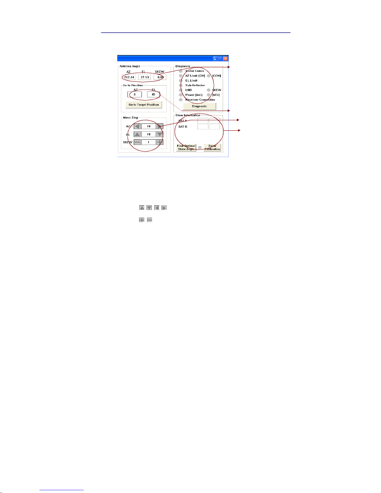
Move Antenna and Execute Antenna Diagnosis
The antenna current p o sit io n
Move the ant enna i n fo ur
directions
Diagnosis results
Target angle to go to
Skew Informat io n
Angle of Antenna
Two kinds of antenna movement is available. One is to move to the
target position and the other is to move by certain amount of angle. The
current position (angle) of the antenna is displayed as “Current” and to
move to the target position, push “Go to target Position” button after
keying in desired angle into “Target”. To move to a certain amount of
angle only, move antenna to direction of up or down, and CW or CCW
by using buttons after keying in the desired angle into the
AZ and EL in the “Mover Step” box. Rotate LNB to direct the skew angle
by using button.
Self-Diagnosis
If “Diagnosis” button is pressed to carry out self- diagnosis of antenna, it
displays the result of self-diagnosis after carrying it out. Blue circle
means the antenna is normal; red represents abnormal and green
represents the antenna is under diagnosis.
Command Button
Go to Target Position – To move the antenna to the present position.
Diagnosis – To diagnose the antenna (BLUE – Passed, RED – Failed,
GREEN – Under diagnosis)

62 i9/i9P Satellite Antenna System – Install and User Manual
Set Antenna Parameters for Control
Product Information
Flag Setting
Parameter Setting
Parameter Setting
Parameter Setting
Command Buttons
Set C o nt r o l Paramet e r– To register parameters values.
Set F lag s – To set f lag set ting f or WRS Met hod o r Off set Di fference.
Product Information – A ntenna dis h size. S erial NO, Vo ltage f or antenna and ACU, Sof tware
versi on fo r ACU and Co ntrol.
Parameter Se tting – To s et antenna p arameter values .
SCAN OFFSET : The act ual ang le b etween the marked po int on sub-ref lec to r and the datum .
TRACK S CALE : To c ontrol the tracking sp eed while antenna is tracking the satellite.
High track s cale v alue resulting in hig h trac king sp eed.
DETECT LEVEL : The basic single detection level.
TRACKING LEVEL : The basic signal tracking level
EL AD JUST : The mechani cal tolerance compens ation o f el evation l imit.
WRS LEVEL : The basic WRS detect ion level.
VOLTAG E THRESHOLD :The v alue to identif y V ertical /Horizo ntal o r RHCP/LHCP
DISE QC THRES HOLD : The v alue t o ident ify 22KHz tone.
OFFS ET DIFF ERENCE : The di ff erence v alue bet ween RHCP /LHCP and SCA N OFF SET .
USE WRS : To appl y WRS while antenna is searching f or satellite.
USE OFF SET D IFFE RENCE : To appl y Off set Diff erence.

Troubleshooting 63
Troubleshooting
Symptom
Possible cause*
12345 6 7 8
Antenna not functioning X
No picture on TV set X X X X
Intermittent picture for short intervals X X X X X X
System works at the dock but not underway X
System will not find satellite X X X X X X X
‘Snowy’ television picture X
Note : * for an explanation of possible cause and their remedies
refer to the following paragraphs
1. Blown fuse, low power or wiring
Check that the in-line quick blow fuse (if fitted) has not blown or the
circuit breaker has not tripped. Replace fuse with one of the same type
and rating. If you have extended the power cable from the antenna unit,
check that there is no power loss. Check the system wiring and
connections.
2. Satellite signal blocked
Satellite signals can be blocked or degraded by buildings, other boats or
equipment on your boat. Check to see if the antenna has a clear view of
the sky.
3. Outside satellite coverage zone
Your system will provide excellent reception within the antenna
coverage area for your satellite television service. However, signal
quality may degrade as you approach the edges of this zone.
4. Radar interference
The energy levels radiated by radar units can overload the antenna a
front-end circuits. Make sure that your antenna is installed as described
in page 8; ‘Selection of Installation Site’.
5. Incorrect or loose RF connectors
As part of the regular maintenance recommended by Intellian
Technologies, Inc., all connections should be checked to ensure that
they have not become loose. A loose RF connector can reduce signal
quality.
6. Multi-switch interference
If you have multiple satellite receiver (IRD) connected to your system,
make sure that you are using an active not passive multi-switch.

64 i9/i9P Satellite Antenna System – Install and User Manual
7. Satellite receiver (IRD) troubleshooting
Your satellite receiver (IRD) may be the cause of less than ideal
operation.
1) Check the satellite receiver’s (IRD’s) configuration to ensure that it is
programmed for the area in which you are operation.
2) Unplug the satellite receiver (IRD) from the power supply for 1
second. Reconnect and allow the system to initialize.
8. LNB fault
If you have an LNB fault, it may require replacing. Contact your local
dealer, national distributor or Intellian Technologies, Inc. product
support for further assistance.

Preparation for Transportation 65
Preparation for Transportation
This is to describe how to fix the antenna internally for transportation, and
the following procedures to fix antenna shall be strictly observed to protect
it from being damaged during transportation.
1. Refer to the drawing.
2. Rotate antenna left and right slowly till the limit switch is pressed.
Don’t rotate it quickly, or you may damage the antenna limit system.
3. Turn the antenna by 360° to the reverse direction.
4. Insert the P.E Foam to back side of the dish and tie pedestal with
three cable ties to fix the antenna in position
5. Cover upper part of Radome being careful for it’s not touching the
reflector, and then assemble upper part of Radome.
6. Pack Intellian i9/i9P into the original package box.
P.E Foam
Cable Tie
2-Cable Tie
WARNINGWARNING

66 i9/i9P Satellite Antenna System – Install and User Manual
Warranty
This product is guaranteed by Intellian Technologies Inc., against defect due
to faulty workmanship or materials and this guarantee covers for 2-year parts
and 1-year labor for labor performed at Intellian Technologies, Inc. service
center from the date of purchase of the product.
You are requested to present a copy of the purchase receipt issued by
Intellian Technologies, Inc. that presents the date of purchase for after sales
service under warranty. In case of failure to present the date of purchase, the
warranty period is to be calculated to 30 days after the manufacturing
production date.
If you discover a defect, Intellian Technologies, Inc. will, at its option, repair,
replace or refund the purchase price of the product at no charge to you,
provided you return it during the warranty period, transportation charges
prepaid, to the factory direct. Please attach your name, address, telephone
number, a description of the problem and a copy of the bill of sale or sales
receipt as proof of date of original retail purchase, to each product returned to
warranty service. Alternatively, you may bring the product to an Authorized
Intellian Technologies, Inc. dealer/distributor for repair.
This Limited Warranty does not apply if the product has been damaged by
accident, abuse, misuse or misapplication or has been modifie d without the
written permission of Intellian Technologies, Inc.; if any Intellian Technologies,
Inc. serial number has been removed or defaced; or if any factory-sealed part
of the system has been opened without authorization

Appendix 67
Appendix : Technical specification
General
Approvals
CE – conforms to
FCC – verified to
EU Directive 89/336/EEC
CFR47:Part 15
Dimensions
Satellite antenna unit
Antenna dish diameter
Antenna control unit
108cm (42.5”) x 110cm(43.3”)
85cm(33.5”)
17.8cm(7”)x21.68cm(8.5”)x5.38cm(2.1”)
Weight
Satellite antenna unit
Antenna control unit
55kg (121.2 lbs)
1.2kg (2.6 lbs)
Environmental
Operating temperature range
Storage temperature range
Humidity limit
-25°C to +55°C
-30°C to +70°C
95% R.H
Operating voltage 10.8 ~ 15.6 V DC
Power consumption Typ. 30W, Max. 50W
Antenna system performance
Frequency Ku-band(10.7 to 12.75 GHz)
Minimum EIRP 44dBW
Azimuth range
680°
Elevation range
-15° ~ +90°
Roll and pitch range
Roll ±25°
Pitch ±15°
Roll and pitch tracking
30° per second
Roll and pitch rate 30° per second

68 i9/i9P Satellite Antenna System – Install and User Manual
Intellian Technologies, Inc.
HQ Dongik Building 7th Flr.,
98 Nonhyun-Dong, Gangnam-gu,
Seoul 135-010, Korea
Tel : +82-2-515-4923
Fax: +82-2-545-4903
Factory SK Ventium 104-501,
522 Dangjeong-Dong, Gunpo-Si,
Kyunggi-Do 435-776, Korea
Phone: +82-31-436-1488
Fax: +82-31-436-1489
R&D Center SK Ventium 104-601,
522 Dangjeong-Dong, Gunpo-Si,
Kyunggi-Do 435-776, Korea
Phone: +82-31-436-2280
Fax: +82-31-436-2284
Intellian technologies USA, Inc.
Parker Business Center, 19
Hammond Suite509 Irvine,
CA 92618 USA
Phone: +1-949-916-4411
Fax: +1-949-271-4183
E-Mail : customersupport@Intelliantech.com
Homepage : http://www.Intelliantech.com
 Loading...