


Global Leader in Marine Satellite Antenna Systems
GX60
Installation and Operation User Guide


Serial number of the product
This serial number will be required for the all troubleshooting or service inquiries.
© 2019 Intellian Technologies Inc. All rights reserved. Intellian and the Intellian
logo are trademarks of Intellian Technologies, Inc., registered in the U.S. and other
countries. The v-Series and the GX60 are trademarks of Intellian Technologies, Inc.
Intellian may have patents, patent applications, trademarks, copyrights, or other
intellectual property rights covering subject matter in this document. Except as
expressly provided in any written license agreement from Intellian, the furnishing
of this document does not give you any license to these patents, trademarks,
copyrights, or other intellectual property. Global Xpress Service
™
or GX™ is a
trademark of Inmarsat PLC and refers to Inmarsat’s xed and mobile, land, maritime
and aero Inmarsat 5 Ka-band satellite services. All other logos, trademarks, and
registered trademarks are the property of their respective owners. Information in
this document is subject to change without notice. Every effort has been made to
ensure that the information in this manual is accurate. Intellian is not responsible for
printing or clerical errors.
Doc. No. UM-N2-190131-V1.9
Disclaimer
The information in this user manual is subject to change without prior notice through
a product life cycle. A printed version of the user manual is periodically updated and
may contain inaccuracies or omissions compared to the recent product information.
The most up-to-date information can be readily accessible on a supplied USB
memory stick or on our website at http://www.Intelliantech.com.

GX60 – Marine Satellite Communication System
4
THIS WAY UP
• Place the boxes/crates on the oor noting the direction of the arrow.
FRAGILE
• Since the Radome is fragile, handle it with care. Do not apply excessive pressure or shock.
These may cause surface cracking or other damage.
DO NOT STACK
• Do not stack boxes/crates as there is a risk boxes/crates may fall and be damaged.
KEEP DRY
• Always make sure the antenna is stored on a dried oor.
• The antenna can withstand ordinary rain. However it water resistance cannot be guaranteed
if submerged.
• Keep the antenna in dried place for sufcient ventilation. Do not store the antenna wrapped
in a tarp, tent, vinyl, and others.
General Precautions
Before you use the antenna, make sure that you have read and understood all safety requirements.

5
Table of Contents
Table of Contents
Certifications 8
Introduction 12
Intellian GX60 Introduction 12
Intellian GX60 Features 13
System Conguration 14
Tools Required for Installation 15
Installing Antenna 16
System Package 16
Antenna Unit 17
BDT (Below Deck Terminal) 18
Installation Kit 19
Planning Installation 20
Selection of Antenna Installation Site 20
Minimize Satellite Blockage 20
Avoid RF Interference 21
RF Hazard Precautions 21
Antenna Dimensions 22
Antenna Mounting Templates 23
Antenna Mounting Hole Pattern 24
Mast Design Recommendation 25
Mast Designing (Installation Example) 26
Position Radome 27
System Cables 28
RF Cable (Customer Supplied) 28
Labeling RF Cables 29
Power Cable (Customer Supplied) 29
Placing Cables on Mast 30
Power Connector Termination 31
Antenna Installation 32
Unpacking Wooden Crate 32
Placing Antenna on Mast 37
Connecting Cables (Customer Supplied) 38
Mounting Radome 39
Turning on Power Switch 40
Installing BDT 42

GX60 – Marine Satellite Communication System
6
Mounting BDT 42
19” Rack Mount Type 42
Table Mount Type 42
BDT Dimensions 43
Selection of BDT Installation Site 43
Connecting Cables to BDT 44
RF Cable Connection 44
Ship Gyrocompass Connection 45
Recommended Cable 45
PC to BDT Communication Setup 46
TCP/IP Connection 46
Wi-Fi Connection 46
Checking Modem Information 47
One-touch Commissioning 48
BDT Connector Guide 49
Operating BDT 51
Introduction 51
Normal Mode 52
Startup 52
Monitoring Current Antenna Status 53
Setup Mode 56
Antenna Settings 57
Manual Search 57
Antenna Diagnostic Test 58
Satellite Settings 60
Load Satellite 60
System Settings 61
Set Location 61
Management 63
Using Aptus PC 64
Introduction 64
Hardware 64
Operating System and Software 64
Software Installation 65
PC to BDT Communication Setup 66
Starting Aptus® 66
Establish Data Communication 67
Auto Update 68
Toolbar Menus 69
System Property Status Dashboard 72
Work View Tabs 75

7
1. Antenna – Basic Info. 75
2. Antenna – Advanced Info. 76
3. Satellite 79
4. Graph View 81
5. Monitor 82
6. Diagnostic / Modem 83
7. GUI 84
8. Work View Functions 85
Using Aptus Web 89
Introduction 89
Main Page 90
Page Login 90
Top Menus 91
Dashboard & Information 92
Antenna Settings 94
Ship Setting 94
Antenna Setting 95
Tracking Setting 97
Diagnostic 98
Library Setting 99
Firmware & Conguration 100
Antenna Firmware Upgrade 100
Antenna Log 102
Antenna Backup & Restore 104
Administration 105
Network Setting 105
User Management 107
iARM Upgrade 108
iARM Save & Reboot 109
Antenna Event Log 110
Modem Information 111
Technical Specification 112
Warranty 113

GX60 – Marine Satellite Communication System
8
Doc Number IT14-DC0901-03
Intellian Technologies, Inc.
EMEA & APAC Headquarters
18-7, Jinwisandan-ro, Jinwi-myeon, Pyeongtaek-Si,
Si,
Gyeonggi-do 451-862, Korea
Tel: +82 2 511 2244
Intellian Technologies USA, Inc.
US Headquarters
9004 Research Drive
Irvine, CA 92618 USA
Tel: +1 949 727 4498
FCC Part 15 Subpart B Declaration of Conformity (DoC)
We, Intellian Technologies, Inc. located at 18-7, Jinwisandan-ro, Jinwi-myeon, Pyeongtaek-si, Gyeonggi-do 451-862,
Korea, declare that the product described below to which this declaration relates is in conformity with the
requirement of the FCC Part 15 Subpart B.
Product Information:
Product Name:
Intellian GX60, 65cm Ka-band Maritime Stabilized Antenna System
Test Result:
noitces eluR tseT dradnatS Test Report Number Result
FCC Part 15
Subpart B
AC power line conducted emission
Section 15.107(a) ICES-003,
Section 6.1, Table 2
SKT-EFC-140043 Pass
Radiation emissions below 1GHz
Section 15.109(a) ICES-003,
Section 6.2, Table 5
SKT-EFC-140043 Pass
Radiation emissions above 1GHz
Section 15.109(a) ICES-003,
Section 6.2.2, Table 7
SKT-EFC-140043 Pass
Supplementary Information:
Notified Body Involved:
(Testing Organization)
SK Tech Co., Ltd.
820-2, Wolmoon-ri, Wabu-up, Namyangju-si, Gyeonggi-do 482-905, Korea
Technical/Compliance
File Held by:
Intellian Technologies, Inc.
18-7, Jinwisandan-ro, Jinwi-myeon, Pyeongtaek-si, Gyeonggi-do 451-862, Korea
Place and Date of issue:
Gyeonggi-do, Korea on September 1, 2014
Authority: Kevin Eom/
Director,
Research and Development
Signature:
Date: September 01, 2014
Certifications

9
Doc Number IT16-DC0502-03
Intellian Technologies, Inc.
EMEA & APAC Headquarters
348-5 Chungho-Ri, Jinwi-Myeon
Pyeongtaek-Si, Gyeonggi-Do, 451-862 Korea
Tel : +82 31 379 1000
Intellian Technologies USA, Inc.
US Headquarters
11 Studebaker
Irvine, CA 92618 USA
Tel : +1 949 727 4498
RED Declaration of Conformity (DoC)
We, Intellian Technologies, Inc. located at 18-7, Jinwisandan-ro, Jinwi-myeon, Pyeongtaek-si, Gyeonggi-do 451-862,
Korea declare under our sole responsibility that the product(s) described in the below to which this declaration relates
is in conformity with the essential requirements and other relevant requirements of the Radio Equipment Directive
(2014/53/EU).
Product Information:
Product Name(s):
Intellian GX60, 65cm Ka-band Maritime VSAT Antenna System
To provide the presumption of conformity in accordance to Annex III(encompassing Annex II) of Directive
2014/53/EU; the following harmonized standards and normative documents are those to which the product ’s
conformance is declared, and by specific reference to the essential requirements of Article 3 of the Directive
2014/53/EU.
1995/5/EC Article
Standard(s) Applied in Full
Result
SAFETY (Art 3.1.a)
EN 60950: A2
Pass
EMC (Art. 3.1.b)
EN 301 843-1
Pass
SPECRTUM (Art. 3.2)
EN 301-360
EN 301-459
EN 303-978
Pass
Supplementary Information:
Notified Body Involved:
(Testing Organization)
DT&C Co., Ltd.
42, Yurim-ro, 154 beon-gil, Cheoin-gu, Yongin-si, Gyeonggi-do 449-935, Korea
Technical/Compliance
File Held by:
Intellian Technologies, Inc.
18-7, Jinwisandan-ro, Jinwi-myeon, Pyeongtaek-Si, Gyeonggi-Do 451-862, Korea
Place and Date of issue:
Gyeonggi-do, Korea on 20 Oct 2012
Authority: Steve Cha Signature: _________ ___
/ CTO, R&D
Date: 20
th
July, 2017

GX60 – Marine Satellite Communication System
10
Doc Number IT14-DC0901-01
Intellian Technologies, Inc.
EMEA & APAC Headquarters
18-7, Jinwisandan-ro, Jinwi-myeon, Pyeongtaek-Si,
Si,
Gyeonggi-do 451-862, Korea
Tel: +82 2 511 2244
Intellian Technologies USA, Inc.
US Headquarters
9004 Research Drive
Irvine, CA 92618 USA
Tel: +1 949 727 4498
C-Tick Declaration of Conformity (DoC)
We, Intellian Technologies, Inc. located at 18-7, Jinwisandan-ro, Jinwi-myeon, Pyeongtaek-si, Gyeonggi-do 451-862,
Korea, declare that the product described below to which this declaration relates is in conformity with the
essential requirements and other relevant requirements of the C-Tick.
Product Information:
Product Name:
Intellian GX60, 65cm Ka-band Maritime Stabilized Antenna System
Test Result:
tluseR rebmuN tropeR tseT tseT dradnatS
AS/NZS CISPR 22
CISPR 22
EN 55022
Conducted disturbance at AC main port SKT-EET-140040 Pass
Conducted disturbance at telecommunication port SKT-EET-140040 Pass
Radiated disturbance below 1GHz SKT-EET-140040 Pass
Radiated disturbance above 1GHz SKT-EET-140040 Pass
Supplementary Information:
Notified Body Involved:
(Testing Organization)
SK Tech Co., Ltd.
820-2, Wolmoon-ri, Wabu-up, Namyangju-si, Gyeonggi-do 482-905, Korea
Technical/Compliance
File Held by:
Intellian Technologies, Inc.
18-7, Jinwisandan-ro, Jinwi-myeon, Pyeongtaek-si, Gyeonggi-do 451-862, Korea
Place and Date of issue:
Gyeonggi-do, Korea on September 1, 2014
Authority: Kevin Eom/
Director,
Research and Development
Signature:
Date: September 01, 2014

11
Doc Number IT14-DC0901-02
Intellian Technologies, Inc.
EMEA & APAC Headquarters
18-7, Jinwisandan-ro, Jinwi-myeon, Pyeongtaek-Si,
Si,
Gyeonggi-do 451-862, Korea
Tel: +82 2 511 2244
Intellian Technologies USA, Inc.
US Headquarters
9004 Research Drive
Irvine, CA 92618 USA
Tel: +1 949 727 4498
EMI Declaration of Conformity (DoC)
We, Intellian Technologies, Inc. located at 18-7, Jinwisandan-ro, Jinwi-myeon, Pyeongtaek-si, Gyeonggi-do 451-862,
Korea, declare that the product described below to which this declaration relates is in conformity with the
essential requirements and other relevant requirements of the IEC60945 and IEC61000-4-2~6/11.
Product Information:
Product Name:
Intellian GX60, 65cm Ka-band Maritime Stabilized Antenna System
Test Result:
tluseR etius tseT esualC .feR dradnatS
IEC60945
ssaP trop main ta emissions detcudnoC 2.9
ssaP zHM 03 woleb snoissime detaidaR 3.9
ssaP zHG 1 woleb snoissime detaidaR 3.9
ssaP zHG 1 evoba snoissime detaidaR 3.9
IEC61000-4-2 10.9 Electrost ssaP )DSE( egrahcsid cita
ssaP )SR( ytinummi detaidaR 4.01 3-4-00016CEI
IEC61000-4-4 10.5 EFT/Burst on AC power ports, and signal and control ports Pass
ssaP strop rewop CA no ytinummi egruS 6.01 5-4-00016CEI
IEC61000-4-6 10.3
Injected current (CS) on AC and DC power ports, signal and
control ports
Pass
IEC61000-4-11 10.7 Power supply short term variation on AC power ports Pass
IEC61000-4-11 10.8 Power supply failure on AC and DC power ports Pass
Supplementary Information:
Notified Body Involved:
(Testing Organization)
SK Tech Co., Ltd.
820-2, Wolmoon-ri, Wabu-up, Namyangju-si, Gyeonggi-do 482-905, Korea
Technical/Compliance
File Held by:
Intellian Technologies, Inc.
18-7, Jinwisandan-ro, Jinwi-myeon, Pyeongtaek-si, Gyeonggi-do 451-862, Korea
Place and Date of issue:
Gyeonggi-do, Korea on September 1, 2014
Authority: Kevin Eom/
Director,
Research and Development
Signature:
Date: September 01, 2014

GX60 – Marine Satellite Communication System
12
Intellian GX60 Introduction
Intellian GX60 is a 65 centimeter Ka-band maritime stabilized antenna, a ready-to-use system for the super-fast,
Global Xpress™ (GX) Ka-band broadband service from Inmarsat. The GX60 offers robust Ka-band RF performance
optimized for Inmarsat GX service with all new GX BDT.
The GX60 BDT combines the Global Xpress Modem internally with the Below Deck Terminal, saving time and space
during installation. The BDT also includes Wi-Fi to allow wireless connection using the dedicated Intellian Aptus
software for system control and monitoring.
The Aptus software automatically congures the antenna system, enabling true One Touch Commissioning. Equipped
with Aptus®, the GX60 antenna can be remotely accessed, monitored and controlled through serial connection or
secured TCP/IP network. Its graphic-based user interface provides easy-to-use operating environment.
The GX60 also has an embedded web server and secured web user interface called Aptus Web for remote management
of the antenna on a web browser. Network connection can be easily setup through the front Management Ethernet
Port on the BDT that supports automatic IP conguration.
The antenna's 3-axis stabilized platform and advanced shock-resistant and vibration damping design of the Pedestal
is fully optimized to withstand the demanding maritime conditions and to ensure reliable broadband communications.
The unlimited azimuth range ensures continuous tracking without unwrapping the cables in the antenna and the low
elevation angle (-20°) supports seamless signal reception at extremely high latitudes.
The GX60 is built to meet or exceed the industry's most stringent standards such as FCC, ETSI, R&TTE. With its
frequency tuned radome and newly designed reector, the GX60 offers the maximized performance on a Ka-band
Inmarsat Global Xpress system.
Introduction

13
Introduction
Intellian GX60 Features
Ka-band optimized reector
The GX60 carbon ber reector is designed and engineered to operate on the Ka-band while maximizing the RF performance.
The reector of the GX60 is designed to be extremely precise and very stable in all operating conditions.
Frequency tuned radome
To ensure efcient operations for Ka-band Inmarsat Global Xpress™ systems, the signal loss of the radome itself is minimized
and the performance maximized with an optimized radome design that enhances the Ka-band system performance.
Combined BDT-Global Xpress™ Core Module
The all new GX BDT combines the Core Module internally with the Below Deck Terminal, saving time and space during installation.
The BDT also includes a Wi-Fi connection to allow wireless connectivity via the dedicated Intellian Aptus software for system
control and monitoring. The Aptus software also helps automatically congure the antenna system during initial commissioning.
Gyro-free satellite search capability
Intellian’s new generation gyro-free satellite search function enables the GX60 to acquire and lock onto the satellite without
requiring a separate input from the ship’s gyrocompass.
Graphical and user-friendly antenna control software: Aptus
®
The GX60 provides a newly developed, graphic-based antenna remote control program with an additional Software Development
Kit (SDK), allowing the NOC or service center to integrate antenna monitoring and control into its existing network management
systems in an easier, user-friendly, and convenient manner.
Dedicated Management Ethernet Port
The GX60 has a Management Ethernet Port on the BDT front that enables direct and simple network connection between a PC
and the BDT. The Management Port allows Internet access and quick access to Intellian's remote management solution, the
Aptus Web.
Wireless access via Wi-Fi
The built-in Wi-Fi wireless network card enables the BDT to be wirelessly connected and can be turned on and off by a switch.
Wireless devices such as PCs, laptops and smartphones can be used to connect to the BDT and monitor, enabling users to
control and change the settings of Intellian antenna system wirelessly.
Industry-leading standards compliance
The GX60 is designed to meet or exceed FCC and ETSI specications, as well as EN60945, EN60950, R&TTE, DNV2.4 Class C
specication.
Automatic satellite switching
The GX60 supports auto satellite and beam switching for seamless continuous coverage.

GX60 – Marine Satellite Communication System
14
System Conguration
For your satellite communication system to work correctly, the system will have to be connected with all of
the provided components as shown in the gure below. A seperate purchase of a satellite modem and ship's
gyrocompass may be required.
Below Deck Terminal(BDT)
PC Interface
Antenna Tx
NMEA
Antenna Rx
PC
Ship’s Gyrocompass
(Not supplied)
AC 100 ~ 240V
(50~60Hz, 4A)
AC 100 ~ 240V
(50~60Hz, 1A)
Antenna

15
Introduction
Tools Required for Installation
Phillips Head Screwdriver
Flat Head Screwdriver
11 mm Wrench
19 mm Wrench
5 mm Allen/Hex key

GX60 – Marine Satellite Communication System
16
System Package
The package of Intellian GX60 consists of antenna unit, BDT and installation kit box.
Antenna unit
BDT
Installation kit box
Installing Antenna

17
Installing Antenna
Antenna Unit
The antenna unit includes an antenna pedestal inside a radome assembly unit. The pedestal consists of a satellite
antenna main dish with RF components mounted on a stabilized pedestal. The radome protects the antenna pedestal
assembly unit from the severe marine environment.
Antenna unit

GX60 – Marine Satellite Communication System
18
BDT (Below Deck Terminal)
The digital VFD (Vacuum Fluorescent Display) allows for easy operation of the BDT, even in the dark.
The functions of the BDT are as follows :
• Setting the satellite
• Editing satellite information
• Setting the antenna parameter
• Setting the antenna manual search
• Setting the LNB local frequency
• Setting block zones
• Setting GPS and Gyrocompass
• Display versions
• Built-in real-time diagnostics function
• Backup and restore the system settings
• Set up the interface with a PC
• Supports Wi-Fi BDT operation
• Recording antenna activities and rmware upgrade through USB
• Built-in web-based remote control management
• Front and rear panel Management Ethernet port
Rear Panel
Front Panel

19
Installing Antenna
Contains the items required for securing the antenna unit and BDT to the vessel.
Installation Kit
BDT box
Description Q'ty Size Remarks
Below Deck Terminal (BDT) 1
43.1 cm x 44.1 cm x 4.4 cm
(17" x 17.3" x 1.7")
Below Deck Terminal
User Manual 1
RF Hazard Sticker 1 Radiation Safety Distance Label
Mounting Template 1
Wi-Fi Antenna 1 110mm
USB Flash Drive 1
Components box
Description Q'ty Size Remarks
BDT Bracket (Rack) 2 BDT-19inch Rack
BDT Bracket (Table) 2 BDT-Table
AC Power Cord (CEEE7/7) 1 1.5m BDT Power
AC Power Cord (USA) 1 1.5m BDT Power
4 Pin Power Connector 1 - CA 3 LD
PC Serial Cable 1 1.8m BDT to PC
USB Cable (A-A) 1 1.8m BDT to PC
Ethernet Cable (RJ45/LAN) 1 1.5m BDT to PC
N to F Adaptor 2 N(Male) to F(Female) Adaptor
Hex Bolt 5 M12 x 100L
Antenna-Deck 4 Sets :
Installation 1 Set : Spare
Flat Washer 5 M12
Spring Washer 5 M12
Hex Nut 10 M12
Hex Head Wrench Bolt 5 M6 x 40L
Radome (Spare Bolts)
Spring Washer and Flat Washer 5 M6
Self-Tapping Screw 5 M4 x 16 Table Mount Bracket
Flat Head Screw 10 M4 x 12L Rack Mount Bracket BDT
Sems Bolt 5 M3 x 12L Table Mount Bracket BDT
Radome Door Key 2 1 Door Key and 1 Spare Key

GX60 – Marine Satellite Communication System
20
Planning Installation
Selection of Antenna Installation Site
The mounting platform should be robust enough and not subject to vibration. The movement of the antenna can
be minimized by installing at the center of the vessel. If these conditions can be only partially satised, nd the
best compromised installation site.
look Angle
-20° to +115°
Obstruction
Antenna
Unit
Minimize Satellite Blockage
Install the antenna in accordance with the following procedures to ensure maximum performance of the antenna.
The ideal antenna site should have a clear view of the horizon or satellite with all around clearance. Please be
sure there are no obstacles within the EL range -20° to +115° from the center of the antenna. Obstacles can
prevent the antenna from transmitting and receiving the satellite signal.
Elevation Limit
of Obstacles

21
Installing Antenna
Avoid RF Interference
Do not install the antenna near the high power short wave radar. Most radar transmitters emit RF energy within
an elevation range of -15° to +15°. For this reason, It is recommended to position the antenna at least 15 feet
(4.6 m) away from the radar.
Rader
Antenna
4.6m
Minimum
Antenna
+15°
-15°
WARNING:
Never place the antenna in the beam path of the radar regardless of distance. The
high power short wave radar may impair its performance or damage the antenna.
RF Hazard Precautions
The antenna is designed to be used with radiation transmit equipment manufactured by others. Exposure to RF
radiation, including exposure associated with an improper use of the transmit equipment, may be hazardous to
persons close to the above deck unit. Ensure safety of personnel who work on the system.
During transmission, ensure to keep the minimum safety distance. The recommended minimum safety distance
to the reector on the focal line is about 15m, based on a radiation level of 5mW/ cm that applies under
occupational/controlled environment. No hazard exists >20° below the antenna's mounting plane.
20°
20°
15m (49ft)
Radiation Safety Distance
15m (49ft)
Antenna

GX60 – Marine Satellite Communication System
22
Antenna Dimensions
The method of installation and mounting of antenna may vary with vessel design, but the following procedures are
applicable in most situations and will result in a secure and effective installation. Conrm the height and diameter
of the antenna before installing it.
ø901.5mm (35.49”)
964.1mm (37.95”)
1029.1mm (40.51”)
60mm (2.36”)

23
Installing Antenna
BOW
Cable Connectors
Radome Bottom
ø445mm (17.51”)
Radome Hatch
Antenna Mounting Templates
The mounting holes must be in the exact same place as shown in the diagram below.

GX60 – Marine Satellite Communication System
24
247.5mm (9.74")
247.5mm (9.74")
Ø445mm (17.51")
Ø160mm (6.29")
Ø200mm (7.87")
4xØ13mm (0.51")
Holes
BOW
NOTE: The hole(Ø160mm (6.29") in the support pedestal is mandatory for installing the
antenna.
Antenna Mounting Hole Pattern

25
Installing Antenna
Less than
1200mm (47”)
More than
1200mm (47”)
Deck
More than
1200mm (47”)
1200mm (47”)
Deck
Mast Design Recommendation
Intellian strongly recommends installing the antenna less than 1200mm (47") above the deck. If the antenna has to be
installed more than 1200mm (47") above the deck, be sure to install it in a safe place where there is enough space to
set the radome aside in case of repair. But once again, the best place for the antenna would be less than 1200mm (47")
above the deck.
WARNING: Do not install unless you secure enough space to repair. Intellian strongly
recommends installing the antenna less than 1200mm (47") above the deck.

GX60 – Marine Satellite Communication System
26
BOW
Gooseneck
BOW
1000mm (39.37")
760mm (29.92")
405mm (15.94") 200mm (7.87")
40mm (1.57")
Min. 10mm (0.4")
Max. 30mm (1.2")
ø45mm (1.77")
ø22mm (0.86")
ø200mm (7.87")
45°
Mast Designing (Installation Example)

27
Installing Antenna
Position Radome
The radome should be positioned with the BOW marker aligned as closely as possible to the ship’s centerline.
Mounting Plate
Min. 10mm (0.4”)
Max. 30mm (1.2”)
Gooseneck
ø45mm (1.77")
Cable Bracket
ø22mm (0.86")
Support Pedestal
Appr. ø254mm (10”)
Min 600mm (24”)
Max 1200mm (47”)
BOW

GX60 – Marine Satellite Communication System
28
System Cables
Before installing the system cables, you need to take the following points into consideration.
1. All cables need to be well secured and protected from physical damage and exposure to heat and humidity.
2. Cable with an acute bend is not allowed.
3. Where a cable passes through an exposed bulkhead or deck head, a watertight gland or swan neck tube
should be used.
Basic System Conguration
Below Deck Unit (BDU)
Above Deck Unit (ADU)
Antenna Tx
NMEA
Antenna Rx
Antenna
Ship’s Gyrocompass
(Not supplied)
AC 100 ~ 240V
(50~60Hz, 4A)
AC 100 ~ 240V
(50~60Hz, 1A)
Below Deck Terminal(BDT)
RF Cable (Customer Supplied)
Due to the signal losses across the length of the RF coax on L-Band, Intellian recommends the following 50 ohm
coax cable types for standard system installations. For cables that run longer than 100 meters, please consult
Intellian Technologies.
Coaxial Cable
Type
Attenuation in
dB/100M
Attenuation in
dB/M
Recommended
Max Cable Length
LMR400 19.6 0.196 60M
LMR600 12.8 0.128 100M
Recommended RF Cables

29
Installing Antenna
Labeling RF Cables
Once the RF cables are connected to the rear BDT, label Tx or Rx stickers for easy identication.
Rx
Tx
Rx
Tx
Antenna
"Tx" Cable
Antenna
"Rx" Cable
Cable Connectors on Rear BDT
Above Deck Unit
Below Deck Unit
Cable Connectors on Radome
Cable Length Cable Cross Sectional Area AWG (American Wire Gauge) Size
Up to 100m 2.5mm
2
13
Up to 200m 4mm
2
11
Power Cable (Customer Supplied)
Intellian GX60 has been designed to work on a vessel’s power supply rated at 100-240V AC. Intellian recommends the
following size of the input power cable for standard system installations.
• After connection, seal the cable gland and tie the power cable securely in place.
• The antenna power is supplied from the power switch box equipped with the circuit breakers, and the power switch box should
be installed near the antenna.

GX60 – Marine Satellite Communication System
30
Placing Cables on Mast
The cables must be routed from the antenna and through various areas of the ship to end up at the Below Deck
Terminal. When pulling the cables in place, avoid sharp bends, kinking, and excessive force. After placement,
seal the deck penetration gland and tie the cables securely in place. The cable bracket must be installed on the
mast to x the relevant cables. The gooseneck must be installed on the side of the mast to protect the relevant
cables against water.
1. Before placing the radome on the mast, the cables should route through the upper gooseneck from the under
gooseneck labeled on the deck to facilitate connecting cables to the antenna as shown in the picture below.
2. Place sufcient cables (about 200mm past the edge of the mounting plate) to provide slack cable connections.
Then, temporarily tie the cables to the cable bracket by using cable ties. After connecting the cables to the
radome, tighten the cable ties to secure cables rmly.
3. Check the cables (RF-Tx/Rx cable, Power cable) are on the top of the mast.
BOW
Rx
Tx
Deck
From Belowdecks
Upper Gooseneck
Mounting Plate
Under Gooseneck
Cable Bracket
WARNING: Ensure that cables have been run through watertight ttings to prevent
water entry into the vessel when installation is completed.

31
Installing Antenna
Power Connector Termination
Bring the 4 Pin Power Connector provided from the components box. To attach the supplied power connector to
the end of your power cable, follow the steps below. The female connector mates with the male connector in the
antenna.
1. Pass the end of the power cable through the connector’s nut and housing as below.
Nut
Housing
2. Strip the jacket from the end of the power cable 22mm. Then strip back the insulation of all three wires 8mm.
Frame Ground / Green (or Yellow)
LIVE / Brown (or Red)
Neutral / Blue (or Black)
3. Connect the wires to the connector as below. Insert the wires to the supplied power connector by using a
at-head screwdriver. Refer to the pin-diagram below.
Connector
1
2 3
Neutral FG
LIVEN.C
4. Slide the housing over the connector and tighten the nut onto the end of the housing. Conrm the completed
power connector as below. Connect one end of the cable to the radome bottom and the other end to the
ship's power.
To ship’s power
To radome
bottom

GX60 – Marine Satellite Communication System
32
Antenna Installation
Unpacking Wooden Crate
The antenna pedestal is shipped completely assembled in its radome. The pallet should be lifted by means of a
suitable sized lifting equipment.
Follow the procedures below.
Step 1.
1. Remove the 16 clips from the edge of the wooden crate by using a at-head screwdriver.
2. After removing the xing screw, lift up the top panel.
WARNING: Do not remove the side panel xed with the xing screw rst. Otherwise,
the wooden sticks xed under the top panel may fall and damage the radome inside
the wooden crate.
Inside View
Wooden Crate
Remove Clips

33
Installing Antenna
Step 2.
1. Take out the BDT box and the installation kit box from the wooden crate.
Lifting Strap
Bolt
Shackle
2. Remove the lifting strap by loosening the bolt in the shackle which connects
the lifting straps on the bottom radome.
Step 3.
1. Loosen the bolts (6EA) on the bottom of the radome using a 5mm hex key. Unbolt the upper dome and keep
the bolts save.
2. Gently lift and remove the upper dome and store it safely while removing shipping brackets.
1
2

GX60 – Marine Satellite Communication System
34
Step 4.
1. Remove shipping brackets securing the AZ axis and EL axis.
B. Remove the AZ shipping bracket
A. Remove the EL shipping bracket
A
B
2. Remove shipping bracket securing the CL axis.
A
Remove the CL shipping bracket

35
Installing Antenna
B. Turn Off Power Switch
A. Normal Mode
A
A
B
B
Step 5.
1. Swich on "NORMAL" mode for operation.
2. Ensure that the power switch is "OFF" during the installation period.

GX60 – Marine Satellite Communication System
36
Step 6.
1. Re-assemble the upper radome and tighten bolts (6EA) on the bottom of the radome using a 5mm hex key.
To ensure security, apply Loctite #242.
1
2
2. Secure the lifting straps by fastening the bolt in the shackle which connects the lifting strap on the bottom
radome. Check on the condition of the lifting strap and make sure the shackle is tightened.
Lifting Strap
Bolt
Shackle

37
Installing Antenna
Step 7.
Using 19mm wrench, remove the nuts (4EA) and washers (4EA) that mount the antenna to the pallet.
WARNING: When lifting the antenna using the lifting straps, make sure to remove the
securing nuts to separate antenna from the pallet.
Placing Antenna on Mast
The Intellian antenna comes with the lifting straps pre mounted from the factory. Before lifting, check the condition
of the lifting strap and that the shackle is tightened up. Ensure the protection is on to avoid damaging the radome.
Lift the antenna above the mast using the crane and maintain sufcient space(150mm) to perform cabling work.
Mast
BOW
Sufcient Space
150mm

GX60 – Marine Satellite Communication System
38
RF Cable(Rx)
RF Cable(Tx)
Radome Bottom View
AC Power
100-240 V ~ 50/60 Hz 3A
Tx Rx
Connecting Cables (Customer Supplied)
Ensure that the power switch of antenna is off during the installation period.
Connect the two(2) RF cables to the antenna RF connectors and Power cable to the antenna power connector.
Rx
Tx
Rx
Tx
“Rx” RF cable
Power cable
“Tx” RF cable
1. RF cables are labeled Tx and Rx for easy installation. Connect the “Tx” RF cable to the Tx connector and the “Rx”
RF cable to the Rx connector as shown in the gure below. Ensure all cables are rmly fastened to the connectors.
After connecting, slide the heat shrink sleeve onto the connector body and cable jacket then heat it to
compress it into place using a hot air gun. Alternatively, use self-amalgamating tape and UV protective
electrical tape.
2. Connect the Power cable to the power connector.
CAUTION: Please ensure that the Tx and Rx cables are correctly connected to the
each Tx/Rx connector on the antenna. Failure to connect the cables to the correct
connector on the antenna will cause system damage.

39
Installing Antenna
Mounting Radome
1. Bolt the radome base directly to the support pedestal. Tighten the Washers/Nuts from bottom to top using
the 19mm Spanner/Torque Wrench.
2. Remove the lifting strap.
NOTE: Make sure when mounting the radome, use the shipping bolts on the
radome's base. Bring the washers/nuts from the components box. Apply Loctite
#262 or equivalent to the bolt thread, and fasten it to a torque setting of 110Nm.
M12 Hex. Bolt
Mounting Surface
Mast
Antenna Unit (Side View)
M12 Flat Washer
M12 Spring Washer
M12 Hex Nut
M12 Hex Nut
19 mm Spanner/Torque Wrench

GX60 – Marine Satellite Communication System
40
Turning on Power Switch
1. Bring the radome door key from the components box. Loosen the screws on the hatch by using the supplied
door key and open the radome hatch.
Radome
Hatch
Door Key
Radome Hatch Hole
Turn on Power Switch
2. Turn On the power switch inside redome to activate the antenna.
WARNING: Ensure that all the hardware and cables have been installed, turn on the
power switch.

41
Installing Antenna
Radome
Hatch
Door Key
3. After turning on the power switch, close the radome hatch and tighten the screws on the hatch by using the
radome door key.
NOTE: After using the door key, store it in a safe place for future use.

GX60 – Marine Satellite Communication System
42
Mounting BDT
Intellian supplies two types of mounting methods 19” Rack Mount Type and Table Mount Type to mount the BDT.
19” Rack Mount Type
- The BDT should be installed using the two supplied Rack Mounting Brackets which allow for a side 19” rack
mounting conguration.
- Using the Flat Head Screw supplied, attach the mounting brackets to the sides of the BDT.
- Place the BDT on the 19” Rack.
- Connect the cables to the rear of the BDT.
Table Mount Type
- The BDT should be installed using the two supplied Table Mounting Brackets which allow for a top or bottom
mounting conguration.
- Using the Sems Bolt supplied, attach the mounting brackets to the sides of the BDT.
- Place the BDT in the location where it is going to be installed.
- Using a pencil to mark the 4 hole positions (2 each side), and use the appropriate drill bit to screw down the
brackets.
- Connect the cables to the rear of the BDT.
WARNING: Ensure that the cables connected to the BDT are long enough to prevent
damage when the BDT is pulled out from the rack.
19" Rack mount type
Table mount type
Installing BDT

43
Installing BDT
Selection of BDT Installation Site
The BDT should be installed below deck, in a location that is:
• Dry, cool, and ventilated.
• The front panel should be easy accessible to user.
BDT Dimensions
47.5cm ( 18.7")
45.5cm (17.9")
43.1cm (17")
20.0cm (7.9")
13.0cm (5.1")
48.5cm (19.1")
46.6cm (18.4")
3.2cm (1.3")
44.0cm (17.3")
4.4cm (1.7")

GX60 – Marine Satellite Communication System
44
RF Cable Connection
Connecting Cables to BDT
CAUTION: Please ensure that the Tx and Rx cables are correctly connected to
the each Tx/Rx connector on the antenna. Failure to connect the cables to the
correct connector on the BDT will cause system damage.
Connect the two(2) Antenna RF cables to the Antenna RF connectors on the rear of the BDT. Connect the
Antenna "Tx" Cable to the "Antenna Tx" connector and the Antenna "Rx" Cable to "Antenna Rx" connector as
shown in the gure below. Ensure all cables are rmly fastened to the connectors.
Antenna
"Tx" Cable
Antenna
"Rx" Cable

45
Installing BDT
Ship Gyrocompass Connection
The ship's gyrocompass provides true heading input to the antenna allowing the antenna to target and acquire
the desired satellite. Intellian always recommends connecting a ship's gyrocompass to the antenna using the
gyrocompass interface on the BDT. If the ship's gyrocompass output is other than NMEA 0183 or NMEA 2000,
the purchase of an NMEA converter may be required. THDs (Transmitting Heading Devices) that are approved for
carriage on certain classications of a vessel or a GPS compass with a compatible NMEA output and heading
sentence can be also used.
Recommended Cable
• NMEA 0183 Gyrocompass Interface Cable (Customer supplied)
• Connector Type: 2 conductors for NMEA 0183, Mini-C 5 pin for NMEA 2000
• NMEA heading sentence: xx HDT (4800 Baud, 8, N,1) If there is no HDT sentence then use HDM sentence
instead.
• NMEA 2000 heading PGN Number = 127250 (Vessel Heading)
Strip the cable insulation back 5mm (0.2")
Do not solder the cable

GX60 – Marine Satellite Communication System
46
PC to BDT Communication Setup
You can establish data communication between a PC and the BDT using one of the following methods.
TCP/IP Connection
Connection through Front Panel Management LAN Port
To connect the BDT to the PC through the Management LAN Port on the front BDT panel, the network should be
congured by setting up the PC IP before the connection. This method requires separate IP conguration on a PC.
1. Connect an Ethernet cable from a PC Ethernet port to the Management Port on the front of the BDT.
2. Go to Control Panel > Network and Sharing Center > Change Adapter Settings. Right-click on the Local Area
Connection and click Properties.
3. Select TCP/ IPv4, and click Properties.
4. Change the network settings on a PC. (Example)
- IP: 192.168.1.11 (Do not use 192.168.1.1~10, which are only for internal use.)
- Subnet Mask: 255.255.255.0
5. Use the following IP address to access Intellian Aptus or Aptus Web page.
- Default IP: 192.168.1.2
PC
Wi-Fi Connection
You can connect to the BDT via Wi-Fi for easy management and control whenever you are on the vessel.
1. Turn on the Wi-Fi power switch located on the rear of the BDT. After 30 seconds, conrm that a red light
appears on the switch.
2. Use the following IP address to access Intellian Aptus or Aptus Web page.
- Default IP: 192.168.1.2

47
Installing BDT
After installation is complete, terminal activation requires a Provisioning Key and Terminal ID of the iDirect modem.
Intellian provides this information in the form of package labels as well as displaying on the Aptus software.
• Provisioning Key and Terminal ID Label
• Label positions
BDT top cover
Aptus software display
BDT package box User manual package
Checking Modem Information
NOTE: The PIK and TID information depends on the serial of the integrated modem and
GX antenna model.
PIK: XXXXXXXXX===
TID: TID: INT-MAR-SCM-XXXXXXX
1 2 3
4

GX60 – Marine Satellite Communication System
48
Ensure to perform One-touch Commissioning after the rst-time connection of the GX terminal and the BDT, after
cable replacement or Ku-to-Ka conversion. Take the following steps for One-touch Commissioning.
Connect an Ethernet cable from a PC Ethernet port to the Front Ethernet Port of the BDT. (See PC to BDT
Communication Setup section for details.)
Open a web browser on the PC and type the default IP address (192.168.1.1) to access the iDirect modem’s web
page.
Login to the iDirect modem page using ID: admin, PW: iDirect123! (or P@55w0rd!).
Click “Commissioning” > “One Touch Commissioning”
Click “Start” button and monitor the progress on the web page.
Check that Commissioning is complete and “BUC Calibration done!” message is displayed.
1.
2.
3.
4.
5.
6.
One-touch Commissioning

49
Installing BDT
BDT Connector Guide
• Console port
Note: Use Cross Serial Cable for PC Interface. (Intellian supplied)
Note: Use Cross Serial Cable for PC Interface. (Intellian supplied)
12345
6789
54321
9876
12345
6789
54321
9876
54321
9876
54321
9876
Pin Signal Pin Signal
1 NC 6 NC
2 Console RX(RS-232) 7 NC
3 Console TX(RS-232) 8 NC
4 NC 9 NC
5 GND
Pin Signal Pin Signal
1 GPS IN+(Spare) 6 GPS IN-(Spare)
2 PC RX(RS-232) 7 NC
3 PC TX(RS-232) 8 NC
4 NC 9 NC
5 GND
BDT console port:
D-sub 9 pin male
Supplied component:
D-sub 9 pin female
BDT PC Interface port:
D-sub 9 pin male
Supplied component:
D-sub 9 pin female
• PC Interface

GX60 – Marine Satellite Communication System
50
• NMEA 2000
• LAN
5
4
3
2
1
Pins
Connector threads
5
3
4
1
2
Sockets
Connector threads
BDT NMEA 2000 port :
male
BDT LAN port
Supplied component:
female
Pin Signal
1 Shield
2
NET-S, (Power supply positive, +V)
3
NET-C, (Power supply common, -V)
4 NET-H, (CAN-H)
5 NET-L, (CAN-L)
Pin Signal Pin Signal
1 TX+ 6 RX-
2 TX- 7 NC
3 RX+ 8 NC
4 NC
5 NC

51
Operating BDT
BDT front keys
Touch key functions
Touch key Function
MENU
Enter SETUP mode
BACK
In SETUP mode, returns to previous menu or option or saves the
adjusted settings.
In Normal mode, returns to the rst page of antenna current status.
FUNCTION
Saves the adjusted settings.
Arrow keys
Selects from the alternative options to increase or decrease the
selected character to a desired value.
OK
Enter next step / menu
PC : PC Cable (USB)
DN : Firmware upgrade or Log data
download (USB)
Management port
Arrow
keys
LED Indicators:
BDT POW, ANT ERR, CM POW, STATUS, TX, NET,
RX1, RX2
Function
OK
BACK
Power
switch
MENU
This section of the handbook describes how to setup your system after installing the BDT.
Introduction
Operating BDT

GX60 – Marine Satellite Communication System
52
I N T E L LI A N TE C HN O L OG I E S I N C .
1. The data communication is being established between the antenna and the BDT.
I N I T IA L I ZE - AN T EN N A I N F O
I N T E LL I A N G X6 0
2. The BDT receives antenna information.
I N I T IA L I ZE - EL PO S I TI O N
I N T E LL I A N G X6 0
3. The elevation angle and cross level angle are initialized.
I N I T IA L I ZE - AZ I MU T H PO S IT I O N
I N T E LL I A N G X6 0
4. The azimuth angle is initialized.
I N I T IA L I ZE - S A T P O SI T IO N
I N T E LL I A N G X6 0
5. The antenna returns to the target satellite position.
SE A RC H 1 0 62 . 6 E I 5_ F 1 S IG : 1 02
A Z : 2 5 4. 3 ( 1 6 4. 3 ) E L: 1 0. 9
6. The antenna is searching for the target satellite.
TR A CK I N G 0 6 2 . 6 E I 5 _ F 1 S IG : 2 01
A Z : 2 5 4. 3 ( 1 6 4. 3 ) E L: 1 0. 9 F n
7. The antenna has locked onto the satellite.
Startup
With the system installed and power applied, the BDT screen will show the following sequence.
Normal Mode
Start up
Initialize antenna info
Initialize elevation &
Cross level angle
Initialize azimuth angle
Initialize target satellite
position
Search status
Tracking status

53
Operating BDT
SE A RC H 1 0 62 . 6 E I 5_ F 1 S IG : 1 02
A Z : 2 5 4. 3 ( 1 6 4. 3 ) E L: 1 0 .9
1. The antenna is searching for the target satellite.
TR A CK I N G 0 6 2 . 6 E I 5 _ F 1 S IG : 2 01
A Z : 2 5 4. 3 ( 1 6 4. 3 ) E L: 1 0 .9 F n
2. The antenna has locked onto the target satellite.
Current IF signal level SIG/ AGC is displayed. SIG will be displayed when NBD (Narrow band
detection) mode for TRACKING SIGNAL is chosen to be used and AGC will be displayed when
DVB mode of TRACKING SIGNAL is chosen to be used.
The symbol “•” will be only displayed when the satellite signal is strong enough to locked onto.
True azimuth [ 254.3] position of the antenna is the sum of ships heading 090.0
[ HDG ] and antenna relative [ 164.3].
S A V E CU RR E N T SA T IN FO ?
Y E S N O
3. Touch FUNCTION key to save current satellite information or abort and return to the main
display. "Fn" will be displayed only if the antenna is in tracking mode.
NOTE: However, if the "GYRO TYPE" is set to "NONE" or "NMEA" but without receiving
a proper input signal, "---.-" will be displayed at "True Azimuth"
Monitoring Current Antenna Status
When the BDT power is on, it displays the status of the antenna. The current status of the antenna is displayed as
shown below.
Current search status
Current tracking status
Save current satellite info

GX60 – Marine Satellite Communication System
54
4. Touch RIGHT arrow key to display NBD, GPS and ship’s heading information.
5. NBD, GPS and ship’s heading information are shown.
- NBD (Narrow Band Detection) IF tracking frequency: 1457000 KHz
- Detected Band Width: 1440KHz
- SIG (Signal Level ): 201
- W (West)/E (East) Longitude: 127.04 ° E
- N (North)/S (South) Latitude: 37.06° N
- HDG (Ship’s Heading): 090.0 degree
- LNB local oscillator (LO) frequency: 18250 MHz
G X1 - 62 - 1 11 A NT S E R I A L 1. 00 / 1 . 0 0
V P - T6 3 AC U S E R I AL 1 .0 0
7. Touch RIGHT arrow key to display the below information.
- Antenna part number, antenna serial number and PCU and Stabilizer rmware version.
- BDT part number, BDT serial number, BDT rmware version.
Touch BACK Key to return to the rst page of the antenna current status.
Tracking & Heading
information
Antenna & BDT
versions
TR A CK I N G 0 6 2 . 6 E I 5 _ F 1 S I G: 2 0 1
A Z : 2 5 4. 3 ( 1 6 4. 3 ) E L: 1 0 .9 F n
NB D F : 1 4 57 0 0 0 B W :1 4 4 0 SI G : 2 0 1
1 2 7 . 0 4E 3 7 .0 6 N H D G: 0 9 0. 0 L : 1 82 5 0 Fn
Current tracking status
8.Touch RIGHT arrow key to display the USB FUNCTION*
This menu will be displayed automatically if a USB ash drive is plugged into the USB port
located in the front panel of the BDT.
USB FUNCTION*
• UPGRADE FIRMWARE: upgrade the system by using the rmware les
(les format: *.FWP) from the specied folder in the USB ash drive.
• COPY LOG DATA: Copy the up-to-date log data from the system to the USB ash drive.
Select
USB
functions
[U S B F U NC T I O N ] S E L EC T U SB F U N C T IO N
U P G R AD E F IR M W AR E
USB

55
Operating BDT
9. Touch OK key to upgrade rmware.
Refer to the error messages below if any errors occur.
UPGRADE FIRMWARE
- FIRMWARE FILE NOT FOUND: the system cannot nd the FWP le.
- INVALID FIRMWARE: the le is not in a recognizable FWP format.
- MORE THAN 1 FILE EXIST: there is more than 1 rmware le that exists from the
specied folder in the USB ash drive.
- CHECK USB CONNECTION: the USB ash drive is not connected.
COPY LOG DATA
- COPY LOG DATA TO USB [30%]: display the copy progress in percentages.
- NOT ENOUGH SPACE IN USB: USB occupies no memory space.
- CHECK USB CONNECTION: the USB ash drive is not connected.
10. Touch RIGHT arrow key to display the real-time diagnostic result.
The real-time diagnostic code will be displayed automatically if there is any error found during
the system operation. However, this page will not be displayed if there is no error message.
11. Touch FUNCTION key to erase diagnostic error message.
Real-time
diagnostic
result
Erase
error message
Upgrade
the
system
[D I AG N O ST I C ] S E N S OR B O X
CO D E1 0 9 R E SU L T S : F A I L E D FN
U PG R AD E ?
Y E S N O
E R A S E D I AG N O ST I C E R R OR L O G ?
Y E S N O

GX60 – Marine Satellite Communication System
56
Setup Mode
Enter the SETUP mode. Simply follow the instructions below.
Searching / Tracking mode
Setup mode
Exit setup mode
TR A CK I N G 0 6 2 . 6 E I 5 _ F 1 S I G: 2 0 1
AZ : 25 4 . 3 ( 16 4 . 3) EL : 10 . 9 Fn
1. While the antenna is in SEARCHING/TRACKING mode, touch MENU key to enter SETUP
mode.
*
indicates the key pad lock function is on (Refer to KEY LOCK menu to setup the key
pad lock function). When key pad lock function is activated touch MENU key or when “Fn” menu
is activated touch FUNCTION key then ENTER PASSWORD menu will be displayed.
S ET U P MO D E ?
Y E S NO
2. Touch LEFT arrow key to move cursor to YES and touch OK key to enter SETUP mode or
touch RIGHT arrow key to move cursor to NO and touch OK key to abort and return to the main
display.
E X I T S E T U P M O D E ?
Y E S NO
3. While the antenna is in SETUP mode, touch FUNCTION key as shortcut key to exit SETUP
mode.

57
Operating BDT
Antenna Settings
Manual Search
Search the desired satellite manually.
Antenna movement
Setup mode
Save
Manual search menu
Antenna menu
S ET U P MO D E ?
YE S NO
1. Touch LEFT arrow key to move cursor to YES and touch OK key to enter SETUP mode.
+ A N T E NN A +S A T E L LI T E
+S Y ST E M
2. Touch OK key to enter ANTENNA menu.
+ M A N UA L SE A R CH +D IA G N OS T IC
3. Touch OK key to enter MANUAL SEARCH menu.
ST E P S IZ E AZ I MU T H E LE V A TI O N AG C
# 00 . 2 #
2 3 1 . 7 4 8 .3 30 1 F n
4. Current IF tracking signal level (AGC)/(SIG/dB scale) is displayed to assist you in manually
peaking AZIMUTH (0°-360°) and ELEVATION (0°-90°) angle for best signal level.
Touch NUMBER key to change the STEP SIZE (Range: 0.1~99.9). Touch LEFT and RIGHT arrow
keys to increase or decrease the azimuth angles. Touch UP and DOWN arrow keys to increase
or decrease the elevation angles.
Touch FUNCTION key to save current settings or abort and return to the main display.
S A V E C U R R EN T SA T IN F O ?
YE S NO
5. If the current settings are able to locate the satellite, touch FUNCTION key to save “current
satellite information”. This will help to reduce the satellite acquisition time after restarting the
system. Touch LEFT arrow key to move cursor to YES and touch the OK key to save the settings.
NOTE: If the gyrocompass type is not NMEA or the gyrocompass is not connected to the
BDT, the information cannot be saved.

GX60 – Marine Satellite Communication System
58
Antenna Diagnostic Test
Refer to the diagnosis codes for the test results.
Single diagnostic test result
Full diagnostic test
Full diagnostic test result
Diagnostic menu
Antenna menu
Setup mode
S ET U P M O D E ?
Y E S N O
1. Touch LEFT arrow key to move cursor to YES and touch OK key to enter SETUP mode.
+A NT E N NA + S A TE L L IT E
+ S Y S TE M + IN S T AL L A T I O N
2. Touch OK key to enter ANTENNA menu.
+ M A N UA L SE A R CH +D I A GN O ST I C
3. Touch arrow keys to move cursor to DIAGNOSTIC menu and touch OK key to enter it.
D IA G N OS T I C C O M MU N I CA T I ON
F U L L T E S T R EA D Y
4. Touch UP and DOWN arrow keys to select a full diagnostic test or single diagnostic test and
touch OK key to execute the selected diagnostic test.
Menus for DIAGNOSTIC are FULL TEST and CODE 101 ~ CODE 116.
D IA G N OS T I C F UL L T E S TI N G
F UL L TE S T
- -
5. A full diagnostic is successfully completed.
D IA G N OS T I C C OM M UN I C AT I O N
C OD E 10 1 RE SU L T : P AS S E D
6. A single diagnostic test is successfully completed.

59
Operating BDT
Diagnosis Code:
CODE 101: The data communication between the antenna and the BDT is tested.
CODE 102: The azimuth motor is tested.
CODE 103: The elevation motor is tested.
CODE 104: The cross-level motor is tested.
CODE 105: The azimuth encoder is tested.
CODE 106: The cross-level encoder is tested.
CODE 107: The rate sensor is tested.
CODE 108: The tilt sensor is tested.
CODE 109: The sensor box motor is tested.
CODE 110: The LNB/NBD is tested.
CODE 111: The LNB pol motor is tested.
CODE 112: The sub-reector is tested. (Skip for v-Series communication products)
CODE 113: The antenna power is tested.
CODE 114: The BDT power is tested.
CODE 115: The receiver power is tested. (Skip for v-Series communication products)
CODE 116: The home sensor is tested.
An example of test result after a full test: •2
•••••••••-••-•
•
: test is passed
2: test is failed (CODE102)
–: test is skipped (TVRO products only)
?: test is in process

GX60 – Marine Satellite Communication System
60
Satellite Settings
Load Satellite
Load
Load sat menu
Load satellite
Satellite menu
Setup mode
S ET U P MO D E ?
YE S NO
1. Touch LEFT arrow key to move cursor to YES and touch OK key to enter SETUP mode.
+A N TE N N A + SA T E LL I T E
+S Y ST E M + I N S TA L L AT I O N
2. Touch RIGHT arrow key to move cursor to SATELLITE and touch OK key to enter it.
+ L O A D SA T .
3. Touch OK key to enter LOAD SAT. menu.
LO A D S AT E L LI T E
[1 ] I 5_ F 1 6 2 .6 0 E
4. Touch UP and DOWN arrow keys to select satellite that you wish to track.
Touch OK key to load the selected satellite.
L O A D ?
YE S NO
5. Touch LEFT arrow key to move cursor to YES and touch OK key to load the selected satellite
and execute the current settings. Or touch RIGHT arrow key to move cursor to NO and touch
OK key to abort and return to the main display.

61
Operating BDT
Set Location
System menu
Set location menu
Gyro type and
Baud rate
Setup mode
S ET U P MO D E ?
YE S NO
1. Touch LEFT arrow key to move cursor to YES and touch OK key to enter SETUP mode.
+A N TE N N A +S A TE L L IT E
+ S Y S TE M + IN S T AL L A TI O N
2. Touch DOWN arrow key to move cursor to SYSTEM and touch OK key to enter it.
+ S ET L OC A T IO N + MA N A GE M E NT
+ K E Y L O C K
3. Touch RIGHT arrow key to move cursor to SET LOCATION and touch OK key to enter it.
G Y R O T Y P E BA U D R A TE
N M EA
4 80 0
4. Set the ship’s GYRO TYPE* and BAUD RATE.
A search pattern 1 or 3 will be initiated according to which gyrocompass type is selected and
the existence of the gyrocompass input. Set the BAUD RATE as 4800, 9600, 19200 or 38400
according to your device.
A search pattern 1 will be initiated automatically if the gyrocompass input does not exist and the
gyrocompass type is selected other than GROUND TEST.
NOTE: The bow offset will not be saved automatically if Search 1 pattern is initiated.
In this case, the antenna will need to re target the desired satellite using Search 1
every time if the antenna restarts.
Gyro search type
Setting of Heading Device
Existence of Heading Data No Device
NMEA /
NMEA 2000
Ground Test
With Heading Data
Search 1 Search 3 Search 3
Without Heading Data
Search 1 Search 1 Search 3
GYRO TYPE*
NO DEVICE
NMEA
NMEA 2000
GROUND TEST
System Settings

GX60 – Marine Satellite Communication System
62
Heading
Latitude & longitude
Save
L A T I T UD E LO N GI T U DE
3 7 . 0 0 N 12 6 .5 0 E
5. Set the current LATITUDE and LONGITUDE
Touch LEFT and RIGHT arrow keys until the desired character is underscored (selected).
Touch UP and DOWN arrow keys to increase or decrease the value, or touch NUMBER keys to
set the desired value directly.
Touch the OK key to set the parameter.
H E A D I NG
09 0 . 0
6. Entry of ship's heading is not required when your system is connected to a NMEA(0813) or
NMEA2000 Heading Gyrocompass output.
Ensure that the supported gyrocompass type is set correctly. If the ship's gyrocompass output
is other than NMEA and Synchro, a purchase of an NMEA converter is required.
S A V E ?
YE S NO
7. Touch LEFT arrow key to move cursor to YES and touch OK key to save current settings, or
move cursor to NO and touch OK key to abort and return to the main display.

63
Operating BDT
S E LE C T P R OC E SS T YP E
BA C KU P U SE R D A T A
4. Touch UP and DOWN arrow keys to SELECT PROCESS TYPE*
Touch OK key to set the parameter and the processing message will be displayed.
SELECT PROCESS TYPE*
BACKUP USER DATA: To backup the antenna settings set by user to the BDT.
RESTORE USER DATA: To restore the antenna by using the backup user data stored from the BDT.
DEFAULT BDT-REMOTE P/W: to default ID and Password of the Web Server.
UPGRADE FROM USB: to upgrade the system by using the rmware les from a specied folder
in the USB ash drive.
COPY LOG TO USB: to copy the antenna log data from the system to the USB ash drive.
BACKUP TO USB: To backup the antenna settings to a specied folder in the USB ash drive.
RESTORE FROM USB: To restore the antenna by using the backup user data from a specied
folder in the USB ash drive.
UPGRADE BDT-REMOTE: To upgrade the system using rmware les (FWP) from a specied
folder in a USB ash drive.
NOTE: UPGRADE FROM USB, COPY LOG TO USB, BACKUP TO USB, RESTORE
FROM USB and UPGRADE BDT-REMOTE options are displayed only if the USB ash
drive is plugged into the USB port located in the front panel of the BDT.
Management
System menu
Backup and restore
menu
Setup mode
S ET U P MO D E ?
YE S NO
1. Touch LEFT arrow key to move cursor to YES and touch OK key to enter SETUP mode.
+A N TE N N A +S A TE L L IT E
+ S Y S TE M + IN S T AL L A TI O N
2. Touch DOWN arrow key to move cursor to SYSTEM menu and touch OK key to enter it.
+ S ET L OC A T IO N + M A N A GE M E NT
3. Touch arrow keys to move cursor to MANAGEMENT menu and touch OK key to enter it.
Select process type

GX60 – Marine Satellite Communication System
64
Intellian’s new VSAT Antenna PC Controller Software, Aptus® is a next-generation graphically based antenna remote
control software. Aptus® allows users to easily and conveniently set up the antenna by using a personal computer.
The minimum PC hardware and software requirements to install and run Aptus® are as follows:
Requirements
Hardware
Hardware Requirements
CPU Intel
®
Pentium® 4 or higher
Memory 512MB or higher
Video Card
DirectX9.0 or higher supported
H/W acceleration supported
Video Memory 128MB or higher
HDD 1GB or higher
Operating System and Software
Software Requirements
Operating System Windows XP SP or higher
Framework Microsoft.Net Framework 3.5 Service Pack 1
or higher
Introduction
Using Aptus PC

65
Using Aptus PC
Software Installation
Double click the ‘Aptus for v-Series Setup.exe’ icon to install Aptus® directly onto your computer/ laptop. The
InstallShield Wizard will guide you through the program setup process. The installation routine provides an icon on
the desktop.
Click the icon to start the software. In addition, Intellian also provides patch les for software upgrade.

GX60 – Marine Satellite Communication System
66
PC to BDT Communication Setup
Starting Aptus®
Double-click the Aptus® desktop icon. The Communication Window will appear to establish the data communication
between your PC and the BDT. Select your choice of connection method to access your BDT through either the
Serial Port Communication or the Network Communication (TCP/IP).

67
Using Aptus PC
Establish Data Communication
Access BDT through Serial Communication
1. Connect a 9 pin serial cable between the PC INTERFACE connector on
the BDT and the 9 pin serial port on the PC. (Or you can use a USB cable
to setup serial connection between a PC and the USB port on the BDT.)
2. Select serial at communication type combo-box.
3. The baud rate of the BDT is 57600.
4. Select a COM port which is not occupied by other devices.
5. Click the Connect button.
Access BDT through Network Communication (TCP/IP)
1. Turn off the wireless connection while using this method.
2. Connect your PC to the Management Port. (See 'PC to BDT Communication
Setup' section for other network connection methods.)
3. Select Network at communication type combo-box.
4. Enter in the BDT’s IP address (Factory default : 192.168.1.2)
5. Enter in the BDT’s port number (Factory default : 4002)
6. Click the Connect button then the Authentication window will appear.
7. Login by using the username and password below:
- Username: intellian (Factory default)
- Password: 12345678 (Factory default)
WARNING:
- Do not plug a USB to the BDT while TCP/IP communication is in use.
Doing so will disable current PC Software Control because the USB
connection has higher priority than TCP/IP connection.
- The amount of data will increase rapidly if Network Communication is in use.
Intellian recommends using Aptus Web.
NOTE: If the remote access PC is located in the same network group with the BDT,
the BDT can be accessed through the internal IP address. But, if the remote access
PC is located outside of the network group, the BDT’s IP address should be changed
to the IP address assigned by the network service provider.

GX60 – Marine Satellite Communication System
68
Auto Update
Intellian Aptus® checks and noties the latest version when it is started to maintain up to date software version by
AutoUpdate function.
1. When Aptus
®
is started, it automatically checks the latest software version from the server and runs AutoUpdate
if new version is available.
2. Current software version information is displayed.
3. It noties new software version information.
4. When you click the “start” button, “File downloading…” message is displayed
while downloading les from the server.
5. When le downloading is nished, “installing…” message is displayed and Aptus patch runs. The installation
starts by InstallShield.
6.Click the “Finish” button when InstallShield installation is nished, then “Run the Aptus” message is displayed and
Aptus runs and AutoUpdate is automatically nished.

69
Using Aptus PC
Quick
File
Toolbar Menus
The toolbar menus at the top of the screen display command buttons of the most commonly used functions of the
Aptus®. The toolbar menus consists of four main menus: Quick (for quick launch of functions), File (for le backup,
restoring and loading), View, and Connection.
Setup: enters Setup mode.
Restart: exits Setup mode and restarts the antenna.
Reboot: reboots the antenna.
Get Ant. Info: obtains the information stored in the antenna
Save Satellite: saves the current bow offset only if the antenna is tracking onto
the satellite. The satellite acquisition time can be reduced signicantly after the
antenna is restarted.
1
2
Backup: backups the antenna information to BDT or PC.
- Select ‘To BDT’ to backup the antenna information to BDT.
The backup le (le format: *.ibf) will be stored on the BDT.
- Select ‘To PC’ to backup the antenna information to a PC.
The backup les (le format: *.rpt and *.ibf) will be generated
on the PC.
Restore: restores the antenna by using the stored information in
BDT or PC.
- Select ‘From BDT’ to restore the antenna by using the stored
information in BDT.
- Select ‘From PC’ to restore the antenna by using the stored
information in PC (le format: *.ibf).
NOTE: Both *.rpt and *.ibf les contain antenna information. However, while *.ibf le can
be used for restoring antenna information, *.rpt le is stored as plain-text for viewing
purpose only. Users can open the *.rpt using text editors such as notepad software.
1
2
3 5 64

GX60 – Marine Satellite Communication System
70
View
3
• User Layout: displays the layout list that the user has previously stored by using
Layout Manager. If you select a layout in this list, the selected layout will be
constructed in Work View screen. The ‘Basic layout’ is provided by default.
• Layout Manager: provides the user with add, delete, and save functionalities in
order to manage the user’s layouts.
- Selecting ‘Add current layout’ opens a pop up window. Type in a desired name of
current layout and click Add, then the new name of the current layout will be saved
to the list under User Layout menu.
- When changes are made to the current layout, select ‘Save current layout’ option.
The current layout will be saved with changes.
- To remove a layout, select ‘Delete layout’ option. Select a desired layout to remove
on the pop up window, then click ‘Delete’. Close the window by clicking on ‘Close’.
The selected layout is removed from the User Layout list.
• Default Layout: returns the current layout to the default layout.
Load Cong. : loads the antenna conguration le (le format: *.cfg).
The conguration le includes the antenna control parameters which are
pre-loaded at the factory and should only be changed by an authorized service
technician. Improper setting of these parameters will cause your system to
perform improperly.

71
Using Aptus PC
Connection
4
Utill
5
• Work View: displays a list of seven pre-constructed
Work View Tabs (Satellite View, Antenna Basic View,
Antenna Advanced View, Monitor View, Graph View,
Diagnostic/Modem View and GUI View) and also
provides the Activate / Close functionalities for each
view tab. Activate the work view tab by ticking the
checkbox next to it.
Help
6
• Communication: At any time, data communication channel can be re-
established between Serial and Network connection. Selecting Comm. Button
will display Communication Window to connect to the BDT via Serial or Network
communication.
• Firmware Uploader: provides the user with the latest rmware version and updates
rmware by simple steps.
• File Manager: display the latest rmware and library le available on Aptus Server.
Select a desired rmware and download to the local PC.
• BDT Log Manager: displays the antenna log data in calendar view which is
downloadable directly to a desired path.
• Setting: enables or disables Auto Update function and sets network connection
time-out.
• Help: 1) Report: provides e-mail contact to Intellian technical support team to let
the user report problems at any time. 2) Information: displays the information of
current Aptus® software version.

GX60 – Marine Satellite Communication System
72
System Property Status Dashboard
The property status dashboard on the left pane of the screen provides the antenna status, the availability of TX
transmission, signal level, GPS and heading status, software information, product information and error status to be
monitored quickly.
Antenna Status: Displays the status of the current mode of the antenna.
- Search 1: A Search 1 pattern will automatically be initiated when the ship’s
heading input does not exist or if it fails. The search cycle will repeat until the
antenna receives the lock signal from the modem or until the DVB transponder
of the target satellite is decoded by the antenna.
- Search 2: Search 2 is reserved for future use.
- Search 3: Search 3 pattern will automatically be initiated when AGC(DVB mode
is in use) or SIG/dB (NBD mode is in use) falls below the current tracking level
threshold value. Once the desired signal is found and above the predened
tracking threshold, the BDT will enter to tracking mode.
- Tracking: Antenna is tracking the target satellite.
- Initialize: Antenna or BDT is initializing.
- Setup: Antenna is in SETUP mode.
1
1
2
3
4
5
6
7
8

73
Using Aptus PC
TX Enable
Displays the status of TX transmit. If the circle next to the TX Enable shows “Blue”,
it means the antenna TX function is enabled. If the circle shows “Red”, it means the
antenna TX function is disabled. The TX function will be enabled only if all ve factors
(Enable Mode, Blockage, Pointing, Modem Lock, and LNB Rotate) listed below show
a “Blue” circle. However, if the “Use TX Mute” function in the ‘BDT System’ Work Tab
is disabled, the TX function will be enabled regardless the above factors.
- Enable Mode: displays whether or not the antenna is in transmitting.
- Blockage: displays whether or not the antenna is pointing in a predened block
zone(s). If the antenna is pointing in the block zone, the circle next to the Blockage
will show “Gray”. If the antenna pointed outside the block zone, the circle next to
the Blockage will show “Blue”.
- Pointing: displays whether or not the antenna is pointing to the target satellite. If
the antenna is mis-pointing to the target satellite, the circle next to the Pointing
will show “Gray”. If the antenna is pointing to the target satellite, the circle next to
the Pointing will show “Blue”.
- Modem Lock: displays whether or not the modem is locked by receiving a
conrmation signal from the satellite modem. If the modem is not locked, the
circle next to the Modem Lock will show “Gray”. If the modem is locked, the circle
next to the Modem Lock will show “Blue”.
NOTE: If the Modem Lock shows “Gray”, check the cable connection between
the antenna system and the satellite modem as well as settings on the modem.
- LNB Rotate: displays whether or not the LNB is rotating. If the LNB is rotating, the
circle next to the LNB Rotate will show “Gray”. If the LNB is not rotating, the circle
next to the LNB Rotate will show “Blue”.
2

GX60 – Marine Satellite Communication System
74
Diagnostic Error Report
The square button next to the Diagnostic Error Report turns red when the system
receives an error. Click the button to see a Diagnostic Report.
8
Signal Level
Shows “DVB” when DVB mode of tracking signal is in use and “NBD” when NBD
mode of tracking signal is in use. The “Red” line indicates the signal “Detect Level
Threshold” and the “Orange” line indicates the signal “Tracking Level Threshold”. If the
signal level is higher than the tracking level threshold, the signal level bar will display
“Blue” color. If the signal level is lower than the tracking level threshold, the signal level
bar will display “Orange” color and the antenna will stay in searching mode.
NOTE: If the signal level is not higher than the tracking threshold, decrease the detect
and tracking level.
GPS and Heading
Displays the current GPS location from the Antenna and Ship’s heading information.
The status light ashes green if the system receives a correct input of the GPS and
Ship’s heading.
Voltage: Displays the antenna and the BDT voltage information.
Software Information: Displays the antenna and the BDT rmware versions, and the
library version.
Product Information: Displays the antenna and BDT serial numbers, antenna model
and BDT model.
3
4
5
6
7

75
Using Aptus PC
How to modify the settings on Work View:
1. Enter the Setup mode by clicking Setup icon.
2. Tick the checkbox next to the “Set” button to modify the settings.
3. Enter the desired value then press the Set button to save the settings.
1. Antenna – Basic Info.
This view tab provides information on the Antenna’s Current GPS location, Heading
Device, Bow Information, Skew Information, and the Antenna’s Angle. This view tab
uses the Antenna’s AZ and EL information as well as the Ship’s Heading information in
order to provide a dynamic graphic user interface (UI).
Work View Tabs
Aptus® provides seven Work View Tabs (Satellite View, Antenna Basic View,
Antenna Advanced View, Monitor View, Graph View, Diagnostic/Modem and GUI to manage the Antenna and the
Satellite conguration.
- GPS: displays and sets current antenna’s GPS.
- Heading: displays and sets current ship’s heading information.
· Heading Device: None / NMEA/ NMEA 2000/Ground Test.
The baud rate (4800/ 9600/ 19200/ 38400) must be set if NMEA is selected.
- Bow Information: displays and sets current antenna’s bow.
- Antenna Angle: displays and sets current antenna’s absolute and relative AZ
(azimuth) position, EL (elevation) position and LNB Pol angle. You can move antenna
azimuth and elevation position and LNB Pol angle by using the arrows or inputting a
value to nd the desired satellite manually.

GX60 – Marine Satellite Communication System
76
2. Antenna – Advanced Info.
This view provides information on the Tilt Sensor Bias, Conical Range, EL Adjust, Rate
Sensor, Search Parameter and Block Zone.
-Tilt Sensor Bias: This maintains the elevation and the cross level axes
in order to keep the pedestal parallel to the horizon. Adjust the two
solid-state tilt sensors to provide absolute cross-level tilt of the antenna and
elevation feedback to eliminate long-term pointing drift (error). Tilt bias must be
adjusted when the antenna control board or sensor box is replaced.
If the bubble on the button level located on the sensor box is
not centered, follow the steps below to adjust the tilt sensor bias.
· Step 1. Enter Setup mode and press the “Ready” button to bring
the elevation and cross-level to 0.
· Step 2. Select “EL” from the drop down list and press Up and
Down arrow keys to adjust the bubble until it is located in the
center ring of the button level.
· Step 3. Select “CL” from the drop down list and press Up and
Down arrow keys to adjust the bubble until it is located in the
center ring of the button level.

77
Using Aptus PC
· Step 4. Press the “Restart” icon to restart the antenna.
- Rate Sensor: is used to calibrate the DC voltage output from the three rate sensors
(azimuth, elevation, and cross-level). These are used to sense antenna motion that
corresponds to the ship’s motion (roll, pitch, and yaw) for stabilizing the pedestal.
The DC voltage output from each of the rate sensors may vary by an amount which is
directly proportional to the direction and rate of motion induced on it.
Before calibrating the rate sensors located in the Sensor box, make sure that the
antenna is placed on a rigid and at platform. During the calibration process, any
motion of the antenna should be avoided as it can affect the antenna’s performance.
Proceed with the following steps to perform the calibration.
· Step 1. Enter Setup mode
· Step 2. Press the “Idle Mode” button to release the elevation and
cross level motor brakes while the antenna is in Setup mode.
· Step 3. Check whether or not the bubble is located at the center
of the button level. If not, move it to the center by following the
previous instruction of Tilt Sensor Bias adjustment.
· Step 4. Press the “Bias Check” button to calibrate the rate sensor.
A blue circle will be displayed next to the Bias Check button if the
calibration is completed. A red circle will be displayed if calibration
failed. A green circle will be displayed during the calibration
process.
- Conical Range: The relative force of the motors controlling azimuth and elevation.
Set the conical range while the antenna is in tracking mode.
- EL Adjust: The elevation adjustment is to offset the angle difference between the
mechanical elevation angle and actual elevation angle. If this value is not properly
adjusted, the antenna may take longer time for satellite search or tracking.
- Search Parameter:
· Wait time: set the time-out for automatic initiation of a search after
the signal level drops below the pre-dened threshold value.

GX60 – Marine Satellite Communication System
78
· Search Step: set increment step size.
· Type 1 & Type 3 (Search 1 & 3) Range: set Search 1 & 3 search
range. Search 3 is conducted in a two-axis pattern consisting of
alternate movements in azimuth and elevation as it forms an
expanding square.
· Type 2 (Search 2) Range: is reserved for future use.
- Block Zone
Displays current block zones by azimuth and elevation sectors. Up to 5 block zones
can be programmed. Once the block zone is created, a blue shading area will be
displayed in the Antenna UI view on the right.
- Threshold Settings
· DVB Detect Level: displays and sets signal detection threshold
level when DVB tracking mode is in use.
· DVB Tracking Level: displays and sets signal tracking threshold
level when DVB tracking mode is in use.
· NBD Detect Level: displays and sets signal detection threshold
level when NBD tracking mode is in use.
· NBD Tracking Level: displays and sets signal tracking threshold
level when NBD tracking mode is in use.
· TX Enable Threshold: displays and sets TX enable threshold.

79
Using Aptus PC
3. Satellite
This view provides information on the Satellite’s Information, Tracking Common
Information, DVB and NBD Tracking Transponder, LNB Local Frequency, and Satellite
Library. This view shows a graphic UI of the current satellite that the
antenna is pointing at and the satellites that are located at a 180° arc on the horizon
with reference to the current position.
NOTE: Based on the satellite EIRP footprint and the size of the antenna, you may not
be able to track all the satellites visible in 180° arc.
- Tracking Information of Current Satellite: displays the current satellite’s name,
longitude position, and satellite skew of the satellite in the library.
- Tracking Common Information: displays the current LNB local oscillator frequency
that is in use and the corresponding voltage supplied. Selects the
tracking mode (DVB / NBD) to be used and sets polarization (Horizontal / Vertical) for
the RX pol and the TX pol.

GX60 – Marine Satellite Communication System
80
- DVB / NBD: sets tracking transponder information for either DVB tracking mode
(Verication Type, Frequency, Symbol rate, and NID) or NBD tracking mode
w(Frequency and bandwidth).
NOTE: DVB and NBD parameter settings should only be changed by an authorized
service technician. Improper setting of these parameters will render your system
inoperable. Consult Intellian for changing antenna parameters.
- LNB Local Frequency: Displays or sets LNB local frequency and its corresponding
LNB voltage supplied. You may select pre-programmed LNB LO settings from the
drop down list. This procedure is same for both the Intellian Global VSAT PLL LNB and
any other LNB.
- Tracking Information of Library: Selecting this option enables “Add Satellite”,
“Edit Satellite", and “Delete Satellite” buttons.
· Eutelsat: Select 'ON' when the antenna is tracking an Eutelsat satellite.
With this option enabled, a dened skew angle for each Eutelsat satellite
is automatically applied without allowing a manual modication to the
skew offset value.
· Get Library From PC : opens the satellite library le (File format:*.ilf)
from the PC.
· Get Data From BDT: obtains the satellite information from the BDT.
· Load Satellite: uploads the satellite information to the BDT.
· Upload to BDT: uploads the satellite library to BDT.
· Edit Satellite: edits the satellite information of the selected
satellite. When Eutelsat satellite is selected, enable Eutelsat option.
This applies dened skew angles for each Eutelsat satellite automatically
and doesn't require manual modication.
· Add Satellite: adds the satellite information as dened in the
current settings.
· Delete Satellite: deletes the selected satellite from the library.
· Save to PC: saves the current library settings to PC.
NOTE: It is required to click the "Save to PC" button after "Edit Satellite", “Add Satellite",
or "Delete Satellite" button is clicked.

81
Using Aptus PC
4. Graph View
This view provides information on Signal, Elevation (EL), Absolute AZ (Azimuth),
Relative AZ, Heading, AZ and EL in Single or Multi graph formats.
- Select Graph Item: shows the graphs of only the checked item(s) in a
Single or Multi Graph View.
- Single Graph View: shows Graph Views per each single Graph Item
selected in ‘Select Graph Item’.
- Multi Graph View: shows one large integrated Graph View of multiple
Graph Items selected in ‘Select Graph Item’.
- Start/Stop Save: the chosen item is saved within the data log. The data
log which stores the information displayed in the graphs can be later
used for a service technician to nd out a cause of any possible problem
to the antenna.
- Clear All: clears everything drawn on the Graph View window.
- Set Pos.: sets the current position as center value of each Graph Item.
- Current Pos.: moves to the location according to values of each Graph Item.
- Span: sets the Display Range(s) of each corresponding Graph Item.
- Period: displays and sets the signal sampling rate.
- Graph Column Count: makes all Graph Views show in either one or
two-column format.

GX60 – Marine Satellite Communication System
82
5. Monitor
This view provides a UI which can monitor all data that has been received from the
BDT.
- Tracking: turns on or off the dish scan function. If the dish scan function
is disabled, the antenna will stop adjusting the antenna pointing angle in
order to optimize the receive signal level.
- Rate Sensor Bias: is used to calibrate the DC voltage output from the
three rate sensors (azimuth, elevation, and cross-level). These are used
to sense antenna motion that corresponds to the ship’s motion ( roll,
pitch, and yaw) for stabilizing the pedestal. You can nd the same
function in Antenna-Advanced View Tab.
- Show Param: shows the current antenna parameters.
- Check NID: veries the NID (network ID) of the current tracking transponder.
Press the NID button to obtain the NID only if the antenna is
locked onto the desired satellite .
- Debug (Start): starts the debug log of the antenna. The debug message
will be displayed once the debug button is pressed.
- Stop Debug: stops debug logging of the antenna.
- Save Log (Start/Stop): starts or stops the logs of the antenna. This
button will be enabled while viewing the debug log. The log message
will be stopped or be saved into a *.txt le once the log button is pressed.
(V_Date.txt.)
- Save Debug (Start/Stop): starts or stops saving the debug log. This button is
enabled once the Start Debug button is pressed.
- Clear View: clears the debug message or log data in monitoring window.

83
Using Aptus PC
6. Diagnostic / Modem
This view provides Antenna Diagnostic Testing and also provides functions to set up
the interface between the BDT and the Intellian VSAT Mediator or the satellite modem.
- Diagnostic : select to run a full diagnostic test or single diagnostic test.
"Green" indicator is displayed for the test under progress.
"Blue" indicates the test result as Pass while "Red" indicates the result as Fail.
"Yellow" indicates the test has been skipped.
· Serial Comm.: tests the data communication between the antenna
and the BDT.
· Motor AZ: tests the azimuth motor.
· Motor EL: tests the elevation motor.
· Motor CL: tests the cross-level motor.
· Encoder AZ: tests the azimuth encoder.
· Encoder CL: tests the cross-level encoder.
· Rate sensor: tests the rate sensor.
· Tilt Sensor: tests the tilt sensor.
· Home sensor: tests the home sensor.
· BDT power: tests the BDT power to see whether or not it is
within the nominal operating range.
· Antenna power: tests the antenna power to see whether or not it
is within the nominal operating range.
· LNB/ NBD: tests the LNB and NBD (narrow band detector).
· Sensor Box Limit: tests the sensor box motor .
- SCM Information: displays the modem information.

GX60 – Marine Satellite Communication System
84
7. GUI
This view shows a graphical representation of the current antenna position which
allows you to easily identify whether or not the antenna is aligned properly to the target
satellite or is in a block zone. In addition, this view shows the current
satellite that the antenna is pointed towards and the satellites that are located at a
180° arc on the horizon, according to the current position.
NOTE: Based on the satellite EIRP footprint and the size of the antenna, you may not be
able to track all the satellites visible in 180° arc.

85
Using Aptus PC
8. Work View Functions
The seven Work View Tabs displayed in the Work View can be arranged in
customized layouts.
- Layout Formatting
· Each of the Work View Tabs can be separated from the rest of the Tabs.
Click and hold the left mouse button on the Work View Tab’s
header and then drag a desired Tab out. When a Work View Tab
is separated from the rest of your Work View Tabs, again click
and hold the left mouse button on the Work View Tab’s header to
display a cross-shaped Navigator icon. While holding the mouse
button, bring the selected Work View Tab closer to the Navigator
icon and release the mouse button at your desired position (top,
left, right or bottom arrow). This time, the selected Tab will be
moved to the desired position.
Move the selected Work View Tab to the top position of the Work
View layout. (See example gure below where Antenna – Basic
Info Tab is moved to the top)

GX60 – Marine Satellite Communication System
86
Move the selected Work View Tab to the right position of the
Work View layout.
Move the selected Work View Tab to the left position of the
Work View layout.
Move the selected Work View Tab to the center position of
the Work View layout.
Move the selected Work View Tab to the bottom position of the
Work View layout.

87
Using Aptus PC
You can also drag multiple Work View Tabs into a customized layout in the same
manner. Click and hold left mouse button on each Work View Tab’s header and drag it
onto a desired arrow on the Navigator icon. Then each Work View Tab can be placed
to the desired positions as shown in the gure below.
The Navigator will appear in each area your mouse pointer is located. To return to the
default layout, select the Default Layout toolbar menu.
- Horizontal or Vertical Tab Group
The Work View Tabs can be also aligned horizontally or vertically. Without
dragging them out, right-click the mouse button on a desired Tab header
and select ‘New Horizontal Tab Group’ or ‘New Vertical Tab Group’
option. Selecting ‘New Horizontal Tab Group’ will separate a selected Tab
from the rest of other Tabs then arrange it in a horizontal format. Likewise,
selecting ‘New Vertical Tab Group’ will separate a selected Tab from the
rest of other Tabs then arrange it in a vertical format.
- Closing the Work View Tab
To close the Work View Tab, right-click the mouse button on a desired
Tab header and select ‘Close’ option in the drop down list. To close all
Work View Tabs except the selected Tab, select ‘Close All But This’
option in the drop down list.

GX60 – Marine Satellite Communication System
88
- Zoom Tool
Using the Zoom tool, you can easily select the magnication you want by
using Zoom In and Zoom Out bar, and Fit in Work View button.
Fit Work View Button: ts the current view to the Work View window size. The button
toggles between the t view and the previous view.
Zoom In and Zoom Out Bar: zooms in and out to expand and reduce the View to the
desired size. (The zoom changes in 10% increments.)
View Switch Button: displays a list of the current views in a list. Choosing one of these
views will display the selected view in the Work View window.
View Name Button: displays the current Work View name.
Close View Button: closes the current view.

89
Using Aptus Web
Introduction
With embedded Remote Access (Aptus Web) function, the v-Series can be monitored, controlled, and diagnosed
remotely from anywhere, anytime through the TCP/IP protocol. This not only can save time but also saves the cost
generated from the hundreds of routine maintenance activities, such as operating rmware upgrades, tracking
parameters resets, and system diagnostic.
How to access Aptus Web:
1. Connect an Ethernet Cable between your PC and the Management Ethernet Port.
2. Enter the BDT's IP address (192.168.1.2) into your web browser's address bar to login into the BDT’s internal
HTML page, if this system has not been changed from the BDT’s factory default.
NOTE: Aptus Web can be displayed in Internet Explorer 7 or later and is also compatible
with Firefox and Chrome web browser.
Using Aptus Web

GX60 – Marine Satellite Communication System
90
Page Login
1. Choose either to Control & Monitor the BDT (Control & Monitoring) or Only Monitor the BDT (Monitoring Only).
2. Log into the BDT by typing in User Name and Password information. If this system has not been changed from
the factory default:
• User Name: intellian
• Password: 12345678
Main Page
GX60
WARNING: The Control & Monitoring Mode will be switched to the Monitoring
Only Mode in the following cases;
• If Aptus is connected using TCP/IP Communication while Aptus Web Control
is in use.
• If Control & Monitoring Mode is accessed while PC Software is running via
TCP/IP Communication. In this case, the web page will display a pop-up
message asking if you want to disconnect the PC Software network
connection. If you select ‘No’, the Control & Monitoring Mode will be switched
to the Monitoring Only Mode.

91
Using Aptus Web
No. Item Description
1
Signal Level Display current signal level.
2
Antenna
status
- Setup: Displays whether or not the antenna is in SETUP mode. The indicator shows “Blue” in
the SETUP mode.
- Initial: Antenna or BDT is initialized.
- Search: Antenna is searching a target satellite.
- Track: Antenna is tracking the target satellite.
3
TX Enable/
TX Disable
Displays whether or not the antenna is able to transmit the data.
4
Restart Restart the antenna system.
5
Setup Enter SETUP mode.
6
Save Sat.
Save current satellite settings.
Bow offset will be adjusted and saved automatically.
7
Ant. Info Obtain current antenna information.
8
Account Shortcut to User Management menu. Change login ID and Password.
9
Logout Logout the BDT's internal HTML page.
Top Menus
Once you log in, the following information and menus are displayed.
1 3 4 5
6
7
8 9
2

GX60 – Marine Satellite Communication System
92
Dashboard & Information
On the left side of the page, Dash Board and Information menus are displayed as below to provide quick monitoring
of the antenna status and settings. Other menus are displayed only in the Control & Monitoring mode and their
functions will be described in the next sections.
1
3
4
5
6
7
8
9
10
11
12
13
14
15
15
2
No. Item Description
1
Dashboard Displays current antenna status to be quickly monitored.
2
Current Antenna
Name
This function is available when:
• the antenna is connected to GX Mediator and GX BDT at the same time.
• "Dual Diversity Conguration" is in "Activate" status. You can select status on the "Network
Setting" menu.
Displays the current antenna name as "Dashboard-Antenna 1 or 2-XX"(XX is antenna
description). You can set the description by accessing GX Mediator Web Server: 192.168.1.4
For more information, refer to the “Mediator User Guide” that came with the GX Mediator package.

93
Using Aptus Web
3
Current Antenna
Position / Target
Antenna Position
Displays current antenna position.
- Relative Azimuth: displays antenna relative AZ angle.
- Absolute Azimuth: displays antenna absolute AZ angle.
- Elevation: displays antenna elevation angle.
4
GPS
Displays current GPS information.
- Longitude (East / West)
- Latitude (North / South)
5
Heading
Device
Displays current Heading Device: NONE, NMEA, NMEA 2000, GROUND TEST. If the ship's
gyrocompass input is other than NMEA separate purchase of NMEA Converter is required.
- Heading: displays ship's heading information.
6
BOW Offset Display current bow offset.
7
DVB Information
Displays DVB tracking mode's current tracking information.
- Frequency: displays tracking frequency.
- Symbol rate: displays symbol rate.
- NID: displays network ID.
- Verify type: displays verication type(AGC, DVB, DVB Decode).
8
NBD Information
Displays NBD tracking mode's current tracking information.
- IF Frequency: displays tracking IF frequency.
- Bandwidth: displays detection bandwidth.
- Base Local: displays base local frequency.
9
Local Frequency
Setting (MHz)
Displays current LNB's local frequency and voltage.
10
Software
Information
Displays current Antenna and BDT rmware versions and Satellite Library version installed in the
system.
- Antenna Stabilizer Version: displays the antenna stabilizer version.
- Antenna PCU Version: displays the antenna PCU version.
- ACU(BDT) Main Version: displays the ACU(BDT) Main version.
- Library Version: displays the Library version.
11
Azimuth
Animation
Shows a graphical representation of the current antenna position to identify whether or not the
antenna is aligned properly to the target satellite or is in a block zone.
12
TX Enable
Displays whether or not the antenna is able to transmit the data. The TX function will only be enabled
(shows BLUE dot ) only if all of the factors listed below shows "BLUE" dot.
- Enable Mode: antenna is not in SETUP mode.
- Blockage: antenna is not facing the predened block zone(s).
- Pointing: antenna is pointing to the target satellite.
- Modem Lock: satellite modem is sending a logic input to the
BDT to identify when the antenna tracks on the correct satellite.
- LNB Rotate: LNB is not rotating.
13
Tracking
Satellite
Displays current tracking mode.
- Satellite Name: displays satellite name.
- Longitude: displays satellite orbit position.
- Skew Offset: displays Skew offset.
- Tracking Method: displays current tracking mode (DVB/ NBD).
- RX Polarization: displays current RX polarization.
- TX Polarization displays current TX polarization.
14
Antenna
Information
Displays the antenna product information.
- Antenna Size: displays the antenna size.
- Antenna Product: displays the antenna product name.
- ACU Product: displays the ACU product name.
- Antenna Serial Number: displays the antenna serial number.
- ACU Serial Number: displays the ACU serial number.
- System Polarization: displays the system polarization.
- System Band: displays the system band.
15
SCM
Information
Displays the Modem information.
- Provisioning Key: displays the provisioning key number.
- Terminal Type: displays the terminal type number.
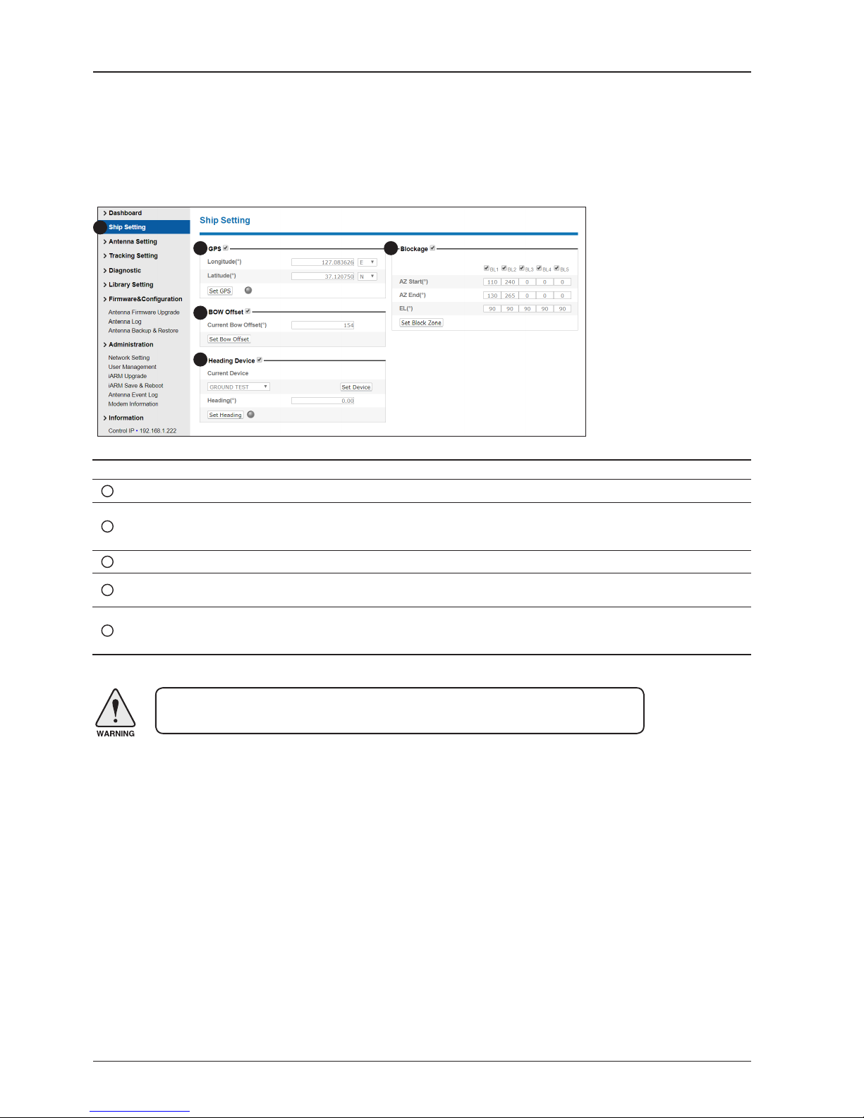
GX60 – Marine Satellite Communication System
94
No. Item Description
1
Ship Setting Set the ship information and block zone.
2
GPS
Set GPS information.
- Longitude (East/West)
- Latitude (North/South)
3
Bow Offset Set Bow Offset if needed.
4
Heading Device
Set ship’s heading device (NONE, NMEA, NMEA2000, GROUND TEST) and ship’s heading
information.
5
Blockage
Set the antenna’s block zones up to 5 by azimuth and elevation sectors. AZ. START is where the
relative azimuth starts and AZ. END is where the relative azimuth ends (Range: 0 - 360°). EL. Limit
is where the elevation starts (Range 0 - 90°).
WARNING: Enter the SETUP mode for conguration. Tick the checkbox before modifying
the settings. After conguration, click ‘Set ...’ button to submit the settings.
Ship Setting
Antenna Settings
1
3
4
5
2

95
Using Aptus Web
Antenna Setting
No. Item Description
1
Antenna Setting
Set current antenna position and Search and Tracking parameters. These parameters
should only be changed by an authorized service technician. Improper setting of these
parameters will render your system inoperable.
2
Current Antenna Position/
Target Antenna Position
Display current antenna position.
-
Relative Azimuth: display antenna relative AZ angle.
-
Absolute Azimuth: display antenna absolute AZ angle.
- Elevation: display antenna elevation angle.
- Heading: display ship’s heading information.
3
Manual Movement Move antenna azimuth and elevation angles to nd the desired satellite manually.
4
Elevation Adjust
Adjust the elevation to offset the angle difference between the mechanical elevation
angle and actual elevation angle.
5
Conical Range
The relative force of the motors controlling azimuth and elevation. Set the conical range
while the antenna is in tracking mode.
6
Idle Mode
Release the elevation and cross level motor brakes while the antenna is in SETUP mode.
The antenna can be moved manually during the mode.
1
3
4
5
6
7
8
9
10
11
2

GX60 – Marine Satellite Communication System
96
WARNING: Tick the checkbox before modifying the settings. After conguration, click
'set...' button to submit the settings.
7
Reboot Reboot the system.
8
Search & Tracking
Parameter Setting
- DVB Detect and Tracking Level Threshold: display / set current detect level threshold
and tracking level threshold when DVB tracking mode is chosen to be used.
- NBD Detect and Tracking Level Threshold: display / set current detect level threshold
and tracking level threshold when NBD tracking mode is chosen to be used.
- TX Enable Threshold: display/set TX enable threshold.
- Wait time: set the time-out for automatic initiation of a search after the signal level
drops below the pre-dened threshold value.
- Search Step: set increment step size.
- Search 1 & 3 Range: set Search 1 & 3 search range. Search is conducted in a twoaxis pattern consisting of alternate movements in azimuth and elevation as forming
expanding square.
- Search 2 Range: is reserved for future use.
9
BUC Keyline Option Sets Disable or Enable to active BUC Keyline.
10
Tilt Sensor Bias
Adjust the two solid-state tilt sensors used to provide absolute cross-level tilt of the
antenna and elevation feedback to eliminate long-term pointing drift (error). Tilt bias
is required to be adjusted when the antenna control board or sensor box is replaced.
Check to see whether or not the bubble is located at the center of the level vial.
11
Rate Sensor Adjust
Calibrate DC voltage output from the three rate sensors used to sense antenna motion
in azimuth, elevation and cross-level axes. During the calibration process, the antenna
should avoid any motion as it can affect the antenna’s performance.

97
Using Aptus Web
Tracking Setting
No. Item Description
1
Tracking Setting
Display or set current tracking mode and tracking frequency of the target satellite.
2
Local Frequency Setting
(MHz)
Display and set LNB’s local frequencies. Display current LNB local frequency which is
in use and voltage.
3
Current Satellite Setting Display and set current satellite setting.
4
Tracking Satellite
Display and set current tracking mode.
- Satellite Name: display and set satellite name.
- Longitude: display and set satellite orbit position.
- Skew Offset: display and set Skew offset.
- Tracking Method: display and set current tracking
mode (DVB/ NBD).
- RX Polarization: display and set current RX
polarization.
- TX Polarization display and set current TX
polarization.
5
DVB Information
Display and set DVB tracking mode’s tracking information.
- Frequency: display and set tracking frequency.
- Symbol rate: display and set symbol rate.
- NID: display and set network ID.
- Verify type: display and set verication type (AGC,
DVB, DVB Decode)
6
NBD Information
Display and set NBD tracking mode’s tracking information.
- IF Frequency: display and set tracking IF frequency.
- Bandwidth: display and set detection bandwidth.
- Base Local: displays base local frequency.
WARNING: Tick the checkbox before modifying the settings. After conguration, click
'set...' button to submit the settings.
1
3
4
5
6
2

GX60 – Marine Satellite Communication System
98
Diagnostic
No. Item Description
1
Diagnostic Execute antenna diagnostic test.
2
Diagnostic
Select to run a full diagnostic test or single diagnostic test.
- Serial Comm.: test the data communication between the antenna and the BDT.
- Motor AZ: test the azimuth motor.
- Motor EL: test the elevation motor.
- Motor CL: test the cross-level motor.
- Encoder AZ: test the azimuth encoder.
- Encoder CL: test the cross-level encoder.
- Rate Senor: test the rate sensor.
- Tilt Sensor: test the tilt sensor.
- Sensor Box Limit: test the sensor box motor.
- LNB/NBD: test the LNB.
- Antenna Power: test the antenna power.
- ACU(BDT) Power: test the BDT power.
- Home Sensor: test the home sensor
- Test ALL: test all devices.
3
Graph
Select to view a graph of AZ Absolute, AZ Relative, EL and Heading data of the antenna.
- A Month: display all data within a month
- A Week: display all data within a week
- A Day: display all data in a day
- Real-time: display data in real time. Press F5 button to refresh.
- Data Num: set the maximum number of graph data set to be displayed.
- View Graph: select to view the data graph.
1
2 3

99
Using Aptus Web
Library Setting
No. Item Description
1
Library Setting Display and set the satellite library information.
2
Library
- Get Library from ACU(BDT): Obtain satellite information installed in the BDT.
- Open Library from PC: open the satellite library le from the
supplied Intellian CD or from the external hard drive/PC. (File format: *.ilf)
- Upload Library to ACU(BDT): upload the satellite library le to BDT.
- Save as Library to PC: save the current library setting to the PC.
3
Load Satellite
Select the satellite that you wish to track and press Load Satellite button to load the selected satellite.
4
Selected
Satellite Setting
Displays selected satellite information.
5
Tracking
Satellite
- Satellite name: displays satellite name.
- Longitude: displays satellite orbit position.
- Skew offset: displays Skew offset.
- Tracking method: displays current tracking mode (DVB/NBD)
- RX polarization: displays current RX polarization.
- TX polarization: displays current TX polarization.
6
DVB Information
Displays DVB tracking mode's tracking information.
- Frequency: displays tracking frequency.
- Symbol rate: displays symbol rate.
- NID: displays network ID.
- Verify type: displays verication type (AGC only, DVB lock, DVB decode, DSS decode)
7
NBD Information
Displays NBD tracking mode's tracking information.
- Frequency: displays tracking frequency.
- Bandwidth: displays detection bandwidth.
- Base Local: displays base local frequency.
8
Local Frequency
Setting (MHz)
Displays LNB local frequency (MHz) and voltage.
1
3
4
5
6
7
8
2

GX60 – Marine Satellite Communication System
100
Antenna Firmware Upgrade
Firmware & Conguration
No. Item Description
1
Antenna Firmware
Upgrade
Upgrade antenna and BDT rmware version.
2
New Antenna
Firmware
Browse and select the rmware to upgrade. Clicking Start Upload button will start to upgrade the
selected rmware.
3
Current Running
Version
Display current rmware version (Antenna STABILIZER,
Antenna PCU, ACU(BDT) main, Library)
4
Live Rollback
Display Previous/Latest Package version and rollback rmware to Previous or Latest version.
During live rollback, the rollback status is displayed on the Top Menu bar. This helps users control
and operate other functions while live rollback is in progress. Once the rollback is complete, the
antenna reboots to apply the changes.
1
3
4
2
 Loading...