


GX100NX
105cm Maritime VSAT Antenna System
Installation & Operation User Guide


Serial number of the product
This serial number will be required for all troubleshooting or service inquiries.
© 2019 Intellian Technologies, Inc. All rights reserved. Intellian and the Intellian logo are
trademarks of Intellian Technologies, Inc., registered in the U.S. and other countries. The
GX100NX is a trademark of Intellian Technologies, Inc. Intellian may have patents, patent
applications, trademarks, copyrights, or other intellectual property rights covering subject
matter in this document. Except as expressly provided in any written license agreement
from Intellian, the furnishing of this document does not give you any license to these
patents, trademarks, copyrights, or other intellectual property. All other logos, trademarks,
and registered trademarks are the property of their respective owners. Information in this
document is subject to change without notice. Every effort has been made to ensure that
the information in this guide is accurate. Intellian is not responsible for printing or clerical
errors.
Disclaimer
The information in this user guide is subject to change without prior notice through a
product life cycle. A printed version of the guide is periodically updated and may contain
inaccuracies or omissions compared to the recent product information. The most up-todate information can be readily accessible on our website at http://www.Intelliantech.com.
Doc. No. UM-V2-190819-V1.0

Table of contents
Precautions
Warnings, Cautions, and Notes 8
General Precautions 8
Certifications
Certications 9
Introduction
Intellian GX100NX Introduction 11
Intellian GX100NX Features 12
Antenna Unit 13
Below Deck Termial (BDT) 13
Antenna Control Unit (ACU) (Optional: for Dual Antenna System) 14
Table of contents
Planning Installation
BDT Components Box 15
ACU Components Box (Optional: for Dual Antenna System) 16
Antenna Specication 17
Antenna Dimensions 17
Heading Alignment 18
Antenna Mounting Hole Pattern 19
Mast Designing (Installation Example) 20
Option2. When Placing Cable Outside Mast 21
Preparing Installation 22
Selection of Installation Site 22
Minimize Satellite Blockage 22
Avoid RF Interference 23
RF Hazard Precautions 23
Preparing System Cables 24
Placing Cable on Mast 25
Installing Above Deck Unit (ADU)
Antenna Installation 26
Unpacking Wooden Crate 26
Removing Antenna from Wooden Crate 28
Placing Antenna on Mast 29
Attaching Waterproof Foam 30
Mounting Radome 31
4

Connecting RF Cable (Customer Supplied) 32
Switching On Power Box 33
Installing Below Deck Unit (BDU)
Selection of BDU Installation Site 34
BDT Dimensions 34
Mounting BDT 35
19" Rack Mount Type 35
ACU Dimensions (Optional: For Dual Antenna System) 36
Mounting ACU (Optional: For Dual Antenna System) 37
19" Rack Mount Type 37
System Congurations 38
Single Antenna System Conguration (Basic Antenna System) 38
Dual Antenna System Conguration (Optional) 39
BDT Cable Connection 40
Name of BDT Rear Panel 40
Connecting to Antenna 40
Connecting to the Switch Router 41
Connecting Ship's Gyrocompass 41
How to Connect NMEA 0183 Gyrocompass Cable 42
Connecting to Additional Secondary ACU (Optional: For Dual Antenna System) 42
BDT Connector Pinouts Guide 43
RS232 Connector (iARM Interface) 43
NMEA 2000 Connector 43
LAN 1~4 Ports 44
BDT to PC Communication Setup 45
TCP/IP Connection 45
Wi-Fi Connection 46
Table of contents
Operating Install Wizard
Turning On System 47
Accessing AptusNX 47
Starting Install Wizard 48
Operating BDT
Introduction 53
Below Deck Termial (BDT) 53
BDT Front Panel 53
BDT Display Menu 54
Startup 56
Diagnosis 58
Antenna Information 60
Interface Information 61
5

USB Function 62
Operating ACU (Optional)
Introduction 67
Antenna Control Unit (ACU) 67
ACU Front Panel 67
ACU Display Menu 68
Startup 69
Diagnosis 71
Antenna Information 73
Interface Information 74
USB Function 75
Using AptusNX
Introduction 80
How to access AptusNX for BDT 80
Main Page 81
Page Login 81
Top Menus 82
Account Menu 83
Account 83
Registration 84
System 85
User Manager 86
Dashboard 87
How to Add & Remove Panels (Dashboard Setting) 87
How to Arrange Dashboard Layout 88
How to Use Shortcut Settings 89
Install Wizard 89
System Tools 90
Firmware Upgrade 90
iARM Upgrade 92
iARM Save & Reboot 93
Satellite Library 94
Graph 95
System Troubleshooting 96
Diagnosis 96
Antenna Log 98
Antenna Event Log 99
Support 99
System Setting 100
Ship Setting 100
Antenna Setting 102
Table of contents
6

Tracking Satellite Setting 105
Network Conguration 106
Modem Info 108
Backup & Restore Setting 110
Mediator Setting (Optional: For Dual Antenna System) 111
Specification
Technical Specication 113
Environmental Specication 114
Warranty
Warranty Policy 115
Appendix A
Using Dual Antenna System (Optional) 116
Table of contents
Appendix B
Performing One Touch Comissioning 117
7

Precautions
Precautions
Warnings, Cautions, and Notes
WARNING, CAUTION, and NOTE statements are used throughout this manual to emphasize important and
critical information. You must read these statements to help ensure safety and to prevent product damage.
The statements are dened below.
WARNING
WARNING indicates a potentially hazardous situation which, if not avoided, could result
WARNING
CAUTION
in death or serious injury.
CAUTION
CAUTION indicates a potentially hazardous situation which, if not avoided, could result in
minor or moderate injury. It may also be used to alert against unsafe practices.
NOTE
A NOTE statement is used to notify people of installation, operation, programming, or
NOTE
maintenance information that is important, but not hazard-related.
General Precautions
Before you use the antenna, make sure that you have read and understood all safety requirements.
THIS WAY UP
• Place the boxes/crates on the oor with the arrow pointing up.
FRAGILE
• Since the Radome is fragile, handle it with care. Do not apply excessive pressure or
shock. These may cause surface cracking or other damage.
DO NOT STACK
• Do not stack boxes/crates as there is a risk boxes/crates may fall and be damaged.
KEEP DRY
• Always make sure the antenna is stored on a dried oor.
• The antenna can withstand ordinary rain. However it water resistance cannot be
guaranteed if submerged.
• Keep the antenna in dried place for sufcient ventilation. Do not store the antenna
wrapped in a tarp, tent, vinyl, and others.
* DO NOT SHIP VIA RAIL: Ensure not to ship any system via Rail.
8

Certifications
Intellian Technologies, Inc.
Certifications
Certications
FCC Part 15 Subpart B Declaration of Conformity
We, Intellian Technologies, Inc. located at 18-7, Jinwisandan-ro, Jinwi-myeon (Chungho-ri), Pyeongtaek-si, Gyeonggi-do
17709 Korea declare under our sole responsibility that the product(s) described in the below to which this declaration relates
is in conformity with the requirement of the FCC Part 15 Subpart B.
Product Information:
Product Name:
Test R e s u l t :
Standard Test Rule Section Test Report Number Result
Intellian GX100NX
AC Power line conducted emission ANSI C63.4:2014
FCC Part 15
Subpart B
Supplementary Information:
Notified Body Involved:
(Testing Organization)
Technical/Compliance
File Held by:
Place and Date of Issue:
Signed by: Kevin Eom Signature: ___ ______
Radiation emissions below 1GHz ANSI C63.4:2014
Radiation emissions above 1GHz ANSI C63.4:2014
DT&C Co., Ltd.
42, Yurim-ro 154 beon-gil, Cheoin-Gu, Yongin-Si, Gyeonggi-Do, 17042, Korea
Intellian Technologies, Inc.
18-7, Jinwisandan-ro, Jinwi-myeon (Chungho-ri), Pyeongtaek-si, Gyeonggi-do 17709
Korea
Gyeonggi-do, Korea on 30
st
May, 2019
DREFCC1905-0170 Pass
DREFCC1905-0170 Pass
DREFCC1905-0170 Pass
/ CTO, R&D
Date: 31
st
May, 2019
Doc Number IT19-DC0531-04
Innovation Center, Global HQ
18-7, Jinwisandan-ro, Jinwi -myeon (Chungho-ri),
Pyeongtaek-Si, Gyeonggi-Do, 1 7709 Korea
Tel : + 82 31 379 1000
9

Certifications
Intellian Technologies, Inc.
EN 301-360 V 2.1.1
Intellian Technologies, Inc.
Korea
RED Declaration of Conformity
We, Intellian Technologies, Inc. located at 18-7, Jinwisandan-ro, Jinwi-myeon, Pyeongtaek-si, Gyeonggi-do 451-862,
Korea declare under our sole responsibility that the product(s) described in the below to which this declaration relates is
in conformity with the essential requirements and other relevant requirements of the Radio Equipment Directive
(2014/53/EU).
Product Information:
Product Name(s):
Intellian GX100NX
To provide the presumption of conformity in accordance to Annex III(encompassing Annex II) of Directive 2014/53/EU;
the following harmonized standards and normative documents are those to which the product’s conformance is declared,
and by specific reference to the essential requirements of Article 3 of the Directive 2014/53/EU.
2014/53/EU Article Standard(s) Applied in Full Result
SAFETY (Art 3.1.a) EN 60950-1:2006 + A11:2009 + A1:2010 + A12:2011 + A2:2013 Pass
EMC (Art. 3.1.b) EN 301 843-1 V2.2.1 Pass
SPECRTUM (Art. 3.2)
EN 301-459 V 2.1.1
Pass
EN 303-978 V 2.1.2
Supplementary Information:
Notified Body Involved:
(Testing Organization)
Technical/Compliance
File Held by:
Place and Date of issue:
DT&C Co., Ltd.
42, Yurim-ro 154 beon-gil, Cheoin-Gu, Yongin-Si, Gyeonggi-Do, 17042, Korea
18-7, Jinwisandan-ro, Jinwi-myeon (Chungho-ri), Pyeongtaek-si, Gyeonggi-do 17709
st
Gyeonggi-do, Korea on 30
May, 2019
Signed by: Kevin Eom Signature: _________ ___
/ CTO, R&D
Date: 31
Doc Number IT19-DC0531-02
Innovation Center, Global HQ
18-7, Jinwisandan-ro, Jinwi -myeon (Chungho-ri),
Pyeongtaek-Si, Gyeonggi-Do, 1 7709 Korea
Tel : + 82 31 379 1000
st
May, 2019
10

Introduction
Introduction
Intellian GX100NX Introduction
Intellian GX100NX is a Ka-band 3-axis stabilized VSAT maritime antenna system. The GX100NX provides
advanced VSAT solutions for Ka-band satellite services. GX100NX is equipped with a new mounting
architecture RF module.
The antenna's 3-axis stabilized platform and advanced shock-resistant, and vibration damping design of the
Pedestal is fully optimized to withstand the demanding maritime conditions and to ensure reliable broadband
communications.
The GX100NX is even more operator-friendly by the integrated RF and power cables in one coaxial cable.
The single coaxial cable carries Tx, Rx, DC power, data and reference signals connecting between antennas
and BDUs.
AptusNX, Intellian’s all-new integrated M&C platform, provides a responsive web user interface to manage and
control antenna systems for all types of devices. Installation Wizard in AptusNX automatically congures the
system functions and minimizes operators’ work for system installation and operation supporting automatic
cable loss compensation, line-up test, and auto diagnostics.
11

Introduction
Intellian GX100NX Features
Single RF Cable
Intellian’s GX100NX incorporates RF cables and power cable into one RF cable. The single cable delivers Tx,
Rx, DC power, FSK and Reference signals between Antenna and BDT.
Mediator embedded in BDT
Mediator function is embedded in BDT which is capable of controlling and managing two GX antenna systems
simultaneously to assign Primary BDT and Secondary ACU without a mediator box.
Standardized Modular Components Across NX Series
Modular components are used throughout the NX range, such as dynamic motor brakes with integrated
encoders, Main Control Unit and skew assembly. Sharing common modules across Intellian’s NX antenna
series, the number of spare parts is reduced.
Quick and Easy Deployment
The GX100NX can be accessed through the external connector at the bottom of radome so that there is no
need to open the radome for installation or pre-test. In addition, the built-in dynamic motor brakes protect the
dish (reector) of GX100NX against any damage in power-off mode, therefore no shipping bracket is required.
AptusNX
Intellian’s all-new integrated M&C platform, AptusNX provides a responsive web user interface to manage
and control the antenna system regardless of device types. It enables advanced alerts from the live data
monitoring and analysis agent, the GX100NX sends warning messages to the NOC in advance when it detects
any abnormal operation. Conguration Wizard in AptusNX automates functions for system conguration so
that operators are minimally involved in system installation and operation, including automatic cable loss
compensation, commissioning test and auto diagnostics.
12

Introduction
Antenna Unit
The antenna unit includes an antenna pedestal inside a radome assembly unit. The pedestal consists of a
satellite antenna main dish with RF components mounted on a stabilized pedestal. The radome protects the
antenna pedestal assembly unit from the severe marine environment.
Figure: Radome and Antenna Unit
Below Deck Termial (BDT)
Below Deck Terminal (BDT) is the unit combined with various interfaces including ACU, Modem (Core Module),
and Ethernet Switch. Below Deck Terminal (BDT) controls Antenna system operation. The following functions
are supported by ACU.
• High power supply for the high power BUC
• Mediator function included
• Spectrum analyzer function included
• OLED display
• USB Log download & Firmware upgrade (No PC required)
• Wi-Fi acess
• AptusNX Web application
Figure: Front Panel of BDT
Figure: Rear Panel of BDT
13

Planning Installation
Antenna Control Unit (ACU) (Optional: for Dual Antenna System)
In Dual Antenna System, the secondary antenna needs to be connected to non-Core Module installed Antenna
Control Unit (ACU) instead of BDT. The following functions are supported by ACU.
• High power supply for the high power BUC
• Spectrum analyzer function included
• OLED display
• USB Log download & Firmware upgrade (No PC required)
• Wi-Fi acess
• AptusNX Web application
Figure: Front Panel of ACU
Figure: Rear Panel of ACU
14

Planning Installation
Planning Installation
Before beginning installation, make sure you have all the included components.
BDT Components Box
Description Q'ty Size Remarks
Below Deck Termial (BDT) Box 1 43.1x41.1x4.4cm Below Deck Termial (BDT) Box
Quick Installation Guide 1
RF Hazard Sticker 1 Radiation Safety Distance Label (15m)
Mounting Template 1
BDT Rack Mount Bracket 2 To x BDT to 19inch Rack Frame
Flat Head Screw 10 M4x12L Bolt Kit for Rack Type Mount Bracket
Hex Bolt 5 M12x80L
Flat Washer 5 M12
Spring Washer 5 M12
Hex Head Wrench Bolt 5 M6x40L
Sems Bolt 2 M4x8L
Radome Door Key 2 Two Door Keys
CableWaterproofFoam 1
USB Cable (A-A) 1 1.8m BDT (Front Panel) to PC
AC Power Cord (CEEE7/7) 1 1.5m BDT Power (220V)
Ethernet Cable (RJ45 / LAN) 2 1m BDT to PC/Intellian M&C
PC Serial Cable 1 1.8m BDT (Rear Panel) to PC
Wi-Fi Dongle 1 Use for Wi-Fi Connection
Bolt Kit to Install Antenna to Antenna
Mast (1 Spare Set Included)
Spare Bolt Kit for Radome AssemblySpring Washer & Flat Washer 5 M6
15

Planning Installation
ACU Components Box (Optional: for Dual Antenna System)
Description Q'ty Size Remarks
Antenna Control Unit (ACU) 1 431x350x44.3 mm Antenna Control Unit (ACU)
Quick Installation Guide (QIG) 1
RF Hazard Sticker 1 Radiation Safety Distance (15m) Label
Mounting Template 1
ACU Rack Mount Bracket 2 To x ACU to 19inch Rack Frame
Flat Head Screw 10 M4x12L Bolt Kit for Rack Type Mount Bracket
USB Cable (A-A) 1 1.8m ACU (Front Panel) to PC
AC Power Cord (CEEE7/7) 1 1.5m ACU Power (220V)
RG-6 RF Cable 2 1m ACU to Modem
Modem Interface Cable
(For iDirect Modem)
Ethernet Cable (RJ45/LAN) 2 1m ACU to PC/Intellian M&C
Wi-Fi Dongle 1
Hex Bolt 5 M12x80L
Flat Washer 5 M12
Spring Washer 5 M12
Hex Head Wrench Bolt 5 M6x40L
Sems Bolt 2 M4x8L
Radome Door Key 2 Two Door Keys
Waterproof Foam 1 X-shape Cable Hole Type
1 1.5m ACU to Modem (iDirect Modem)
Bolt Kit to Install Antenna to Antenna
Mast (1 Spare Set Included)
Spare Bolt Kit for Radome AssemblySpring Washer and Flat Washer 5 M6
16

Planning Installation
Antenna Specication
Antenna Dimensions
Conrm the height and diameter of the bottom surface of the antenna unit before installing it. The mounting
surface and overall space occupied by the antenna must be sufcient for the height and diameter of the fully
constructed radome. The height and the diameter of the bottom surface of the antenna are as shown in the
following drawing. It is strongly suggested that the installation is conducted using a crane.
Ø1379 mm (54.29")
Figure: Antenna Dimensions
1454 mm (57.44")
17

Planning Installation
Heading Alignment
The radome assembly should be positioned with the BOW marker aligned as close as possible to the center
line of the ship.
BOW
Direction
BOW
Direction
Radome Hatch
Front View
Radome Hatch
Cable Entry
Bottom View
Figure: Antenna Heading Alignment
18
Cable Entry Cover

Antenna Mounting Hole Pattern
The mounting holes must be in the exact same place as shown in the diagram below.
4-ø13 Holes
Planning Installation
247.5mm (9.74”)
ø445mm (17.5”)
Figure: Antenna Mounting Hole Pattern
247.5mm (9.74”)
ø445mm (17.5”)
19

Planning Installation
Mast Designing (Installation Example)
The installation mast must be robust enough to prevent ex, vibration, and sway when an external force is
exerted on the mast with antenna and radome. Refer to the following mast drawing for more details.
Option1. When Placing Cable Inside Mast
BOW
247.5 mm (9.74")
4- ø13 mm (0.51")
247.5 mm (9.74")
ø110 mm (4.3")
ø254 mm (10")
Gooseneck
Min. 10 mm (0.39")
Max. 20 mm (0.78")
ø45 mm (1.77")
1000 mm (39.37")
ø22 mm (0.86")
800 mm (31.49")
200 mm (7.87")
Figure: Recommended Size of Mast (Option1)
20

Option2. When Placing Cable Outside Mast
BOW
247.5 mm (9.74")
247.5 mm (9.74")
Planning Installation
4- ø13 mm (0.51")
ø254 mm (10")
Min. 10 mm (0.39")
Max. 20 mm (0.78")
ø22 mm (0.86")
1000 mm (39.37")
840 mm (33.07")
200 mm (7.87")
Figure: Recommended Size of Mast (Option2)
21

Planning Installation
Preparing Installation
The antenna installation requires extreme precaution and safety measures given its size and weight. Failure to
follow the correct installation process may lead to injury of the installer and/or cause damage to the system.
In order to maximize the performance of the system, a thorough review of this installation guide is strongly
recommended, as well as executing the installation process as it is noted in this manual.
Selection of Installation Site
The system should be placed in an area onboard the vessel with little to no RF signal blockage. When the antenna
is transmitting, obstacles in way of the beam path will cause decreased satellite signal strength. The antenna
unit should have direct line-of-sight with the desired satellite without any obstacles in the beam path. Certain
minimum distances between the antenna and other onboard devices must also be considered during installation.
Minimize Satellite Blockage
Install the antenna in accordance with the following procedures to ensure maximum performance of the
antenna. The ideal antenna site should have a clear view of the horizon or satellite with all around clearance.
Please be sure there are no obstacles within the EL range -20° to +115° from the center of the antenna.
Obstacles can prevent the antenna from transmitting and receiving the satellite signal.
Antenna Unit
Look angle
-20° to +115°
Obstruction
Figure: Elevation Limit of Obstacles
22

Planning Installation
Avoid RF Interference
Do not install the antenna near the high power shortwave radar. Most radar transmitters emit RF energy within
an elevation range of -15° to +15°. For this reason, It is recommended to position the antenna at least 15 feet
(4.6 m) away from the radar.
Antenna
+15°
Radar
-15°
Antenna
Minimum
4.6m
Figure: Potential RF Interference
WARNING
Never place the antenna in the beam path of the radar regardless of distance. The high power
WARNING
shortwave radar may impair its performance or damage the antenna.
RF Hazard Precautions
The antenna is designed to be used with radiation transmitting equipment manufactured by others. Exposure
to RF radiation, including exposure associated with an improper use of the transmit equipment, may be
hazardous to persons close to the above deck unit. Ensure the safety of personnel who work on the system.
During transmission, ensure to keep the minimum safety distance. The recommended minimum safety
distance to the reector on the focal line is about 15m, based on a radiation level of 5mW/cm that applies
under occupational/controlled environment. No hazard exists >20° below the antenna's mounting plane.
Radiation Safety Distance
15m (49ft) 15m (49ft)
Antenna
20° 20°
Figure: RF Hazard Precautions
23

Planning Installation
Preparing System Cables
Before installing the system cables, you need to take the following points into consideration.
1. All cables need to be well clamped and protected from physical damage and exposure to heat and humidity.
2. A cable with an acute bend should be avoided.
3. Wherever a cable passes through an exposed bulkhead or deck head, a watertight gland or swan neck
tube should be used.
For cables that run longer than Intellian's recommendations, please consult Intellian Technologies.
• RF Cable (Customer Supplied)
Due to the signal losses across the length of the RF coax on L-Band, Intellian recommends the following
50 coax cable types for standard system installations. For cables that run longer than 120 meters (except
LMR600 coaxial cable type), please consult Intellian Technologies.
* The Maximum DC Resistance of RF Cable is 0.8 Ohm.
* Tightening Torque Value: N Type Connector, 1.5 N-m
Coaxial Cable Type
LMR400 19.6 0.196 80M
LMR600 12.8 0.128 120M
Attenuation in dB/100M
(@ 2GHz)
Attenuation in dB/M
(@ 2GHz)
Recommended
Max. Cable Length
• Gyrocompass Cable (Customer Furnished)
Due to the environment of various types of vessels, Intellian recommend the general cable types compatible with
the antenna.
NMEA 2000 NMEA 0183
Connector Type Mini-C 5 pins connector 2 pins terminal block connector
Cable Type 5 wires within a single cable
Heading Information
Supports PGN, 127250: Vessel
Heading
2-wires constructed with one
enclosed shield cable
Supports $HEHDT , baud rate 4800,
format 8N1 as standard.
24

Planning Installation
Placing Cable on Mast
The cable must be routed from the antenna and through various areas of the ship to end up at the antenna
control unit. When pulling the cables in place, avoid sharp bends, kinking, and excessive force. After
placement, seal the deck penetration gland and tie the cable securely in place. The cable bracket must be
installed on the mast to x the relevant cable. The gooseneck must be installed on the side of the mast to
protect the relevant cable against water.
WARNING
Ensure that cable has been run through watertight ttings to prevent water entry into the vessel when
WARNING
Option1. Placing Cable Outside Mast
1. Place the cable from the gooseneck labeled on the deck to
the antenna as shown in the picture.
2. Maintain a sufcient cable length (more than 2M) from the
surface of the mast. After connecting the cable to cable
connector inside the cable entry, adjust the cable length and
then x the cable on the cable bracket by using cable ties.
installation is completed.
Sufcient Cable
Cable Brackets
Sufcient Cable
Upper
Gooseneck
Cable Brackets
Under
Gooseneck
Gooseneck
To Belowdecks
Figure: Cabling on Outside of Mast
Option2. Placing Cable Inside Mast
1. Before placing the radome on the mast, the cable should
route through the upper gooseneck from the under gooseneck
labeled on the deck to facilitate connecting RF Cable to the
antenna as shown in the picture.
2. Maintain a sufcient cable length (more than 2M) from the
surface of the mast. After connecting the cable to cable
connector inside the cable entry, adjust the cable length and
then x the cable on the cable bracket by using cable ties.
To Belowdecks
Figure: Cabling on Inside of Mast
25

Installing Above Deck Unit (ADU)
Installing Above Deck Unit (ADU)
Antenna Installation
Unpacking Wooden Crate
The pallet should be lifted by means of a forklift.
1. Locate one of the side panels with a paper sticker (Unpack Guide). Detach this side panel by removing
the xing screw (1 EA) and clips (6 EA).
CAUTION
Be careful with the direction of the panel that you must open rst.
CAUTION
To unpack the wooden crate, follow the procedure below.
1-1
1-2
: 1 EA
: 6 EA
Fixing screw
1-3
Fixing clip
2. The BDT box is located inside the side panel. Take out the BDT box by removing xing screws (2 EA) on
the BDT bracket.
2-1
26

Installing Above Deck Unit (ADU)
3. Running Diagnostic Tests: This step is optional. After removing one of the side panels, you can run
the diagnostic tests easily to verify the condition of the antenna. First, prepare the "RF Cable (Customer
Supplied)" to connect the antenna and the BDT.
3-1. Remove the M4x15L Wrench Bolt by using the wrench set then open the cable entry cover.
3-2. Connect the "RF Cable
(Customer Supplied)
" from the "ANTENNA" connector on the rear of the BDT to
the "RF Connector" inside cable entry of radome (Antenna).
3-3. Execute diagnostic tests (Full Diagnosis Test) via BDT and check the real-time diagnosis result.
Optional
3-1
Cable Entry Cover
3-2
RF Cable (Customer Supplied)
3-3
A P
SNR HDG:120.4
SEARCH 1 128.0 E
CM STS NET TX RX1 RX2
GPS:
4. Remove the clips (6 EA) on the top panel. Detach the top panel by carefully pulling it as shown in the
picture.
Press
Move Key
DIAGNOSIS
DIAG ALL
Press
Select Key
WARNING
4-1
WARNING
The side brackets at the edge of the top panel secure the side panels and top panel in position. When
pulling the top panel, ensure that the top panel doesn't fall on the radome.
: 6 EA
4-2
27

Installing Above Deck Unit (ADU)
5. Remove the xing screws (7 EA) from the remaining side panels, then detach the side panels.
: 7 EA
5-35-25-1
Removing Antenna from Wooden Crate
Four radome brackets secure the antenna to the pallet. To remove the radome bracket, follow the procedures
below.
1. Remove the hex head wrench bolt (2 EA) on the radome bracket that secures the antenna to the pallet
using a wrench.
Fixing Bolt (2 EA)
2. Check the condition of lifting strap to make sure the shackles (2 EA) are tightened. Re-wrap the shackles
with the existing protection to avoid radome damage.
Shackles (2 EA)
Lifting Strap
3. Lift the antenna above the bottom pallet using the crane, and maintain sufcient
space (max. 100 mm) to remove the shipping brackets.
WARNING
• When lifting the antenna using the lifting straps, make
sure to remove the securing radome brackets to separate
antenna from the pallet.
WARNING
• Be careful when lifting the heavy object. Incorrect
handling of the heavy object may lead to injury to the
installers and/or cause signicant damage to the unit.
Sufcient Space
(max. 100 mm)
28

Installing Above Deck Unit (ADU)
4. Remove the radome bracket bolt (1 EA) using a wrench, then detach the radome bracket from the radome.
5. After removing radome bracket, apply Loctite #263 to the bolt's threads to ensure the bolts are fastened
rmly. Fully tighten the detached radome bolt (1 EA) using a wrench. Apply the same procedure to all four
parts.
1
Radome
Bracket
B
A
Radome
Bracket Bolt
2
Fully Tighten Radome Bolt
Placing Antenna on Mast
The Intellian antenna comes with the lifting straps pre-mounted from the factory. Check
the condition of the lifting strap ensure the shackle is tightened up. Lift the antenna
above the mast using a crane and carefully put the antenna down on the mast. When
placing the radome, consider that the antenna should be positioned with the BOW
marker aligned as close as possible to the ship's heading.
Radome
Bolt
WARNING
WARNING
The antenna may be subject to swaying motions in windy conditions.
Be careful when handling the antenna.
29

Installing Above Deck Unit (ADU)
Attaching Waterproof Foam
The waterproof foam must be attached to prevent water from penetrating inside the Radome before fully
mounting the radome to the mast. Make sure the foam is attached in the same position as in the picture below.
Adhesive
Tape
Cable Hole
(X-shape)
Waterproof Foam
Attaching Position of Waterproof Foam
Case 1. When Placing Cable Outside Mast
1. Peel off the paper from the supplied waterproof foam to expose the adhesive.
2. Attach the waterproof foam rmly onto the surface of the cable access hole.
3. Pull the RF cable from the mast.
B
A
Cable
Access Hole
Position of
Waterproof
Foam
Case 2. When Placing Cable Inside Mast
1. Peel off the paper from the supplied waterproof foam to expose the adhesive.
2. Pull the RF cable from the mast through the cable hole (X-shape).
3. Then attach the waterproof foam rmly onto the surface of the cable access hole. When moving the
radome, be careful not to let the waterproof foam or the cable fall down.
A
B
30

Installing Above Deck Unit (ADU)
Mounting Radome
Bring the Bolt Kit (4 EA) from the BDT box. Before assembling bolts, apply Loctite #263 to the bolt's threads
to ensure the bolts are fastened rmly. Insert the bolts and washers from under the mast into the radome,
and fasten them to the nuts assembled inside the radome. After mounting the antenna on the mast, remove
the lifting strap.
M12 Flat Washer
M12 Spring Washer
M12x80L Hex. Bolt
Use 19 mm Spanner/
Torque Wrench
NOTE
NOTE
• Make sure the cable from the mast is aligned with the cable entry of antenna bottom for a stable
connection.
• If the mast's surface thickness is greater than 20 mm, use a M12x100L Hex Bolt.
• To fasten the M12 bolts use a torque setting of 110Nm.
31

Installing Above Deck Unit (ADU)
Connecting RF Cable (Customer Supplied)
Connect the "RF Cable" from the "ANTENNA" connector on the rear of the BDT to the "RF Connector" inside
the cable entry of radome. In the cable connection on both sides, cable termination should be completed using
suitable tools. After connecting, securely x the cable by using the cable ties in place.
1. Remove the M4x15L Wrench Bolt by using the wrench set then open the cable entry cover.
M4x15L Wrench Bolt
NOTE
After removing the M4x15L Wrench Bolt from the cover of cable entry, Keep it in a safe place for the
NOTE
next step. When closing the cover of cable entry, this bolt must be used.
2. Terminate N(M) connector on the end of the RF Cable. Intellian recommends using a genuine cable
connector and tools. Refer to the cable termination instructions provided by the manufacturer to terminate
the N connector.
3. Connect the terminated RF cable to the connector as shown in the gure below. Ensure the cable is rmly
fastened to the connector. Fasten the cable with cable ties using the cable mount or cable clamp along
the routing path.
Cable Tie
Bracket
4. After completing cable connection, put the cover in the right place and tighten the M4x15L Wrench Bolt
by using the wrench set.
32

Installing Above Deck Unit (ADU)
Switching On Power Box
Access the ADU modules inside the radome to check that the power switch is on through the radome hatch.
Make sure that there is sufcient free space underneath the ADU to open the radome hatch.
1. Bring the radome door key from the BDT box. Open the radome hatch by turning the xed bolts
counterclockwise by using the radome door key.
2. The power box switch was turned on and shipped from the factory. Check the power box inside the
radome is switch on. If not, switch on the power box.
3. Put the radome hatch in the right place. Close the radome hatch by turning the xed bolts clockwise by
using the radome door key.
Door Key Provided
NOTE
NOTE
After using the door key, store it in a safe place for future use.
33

Installing Below Deck Unit (BDU)
Installing Below Deck Unit (BDU)
Selection of BDU Installation Site
The BDU should be installed below deck, in a location that is:
• Dry, cool and ventilated.
• The front panel should be easily accessible to users.
BDT Dimensions
Conrm the dimension of the BDT before installing it.
431 mm (16.96")
466 mm (18.34")
485 mm (19.09")
Figure: BDT Dimensions
411 mm (16.18")
437 mm (17.20")
32 mm (1.25")
44.3 mm (1.74")
34

Installing Below Deck Unit (BDU)
Mounting BDT
Intellian supplies 19" Rack Mounting Brackets to mount the BDT in a rack.
19" Rack Mount Type
The BDT should be installed using the two supplied 19" Rack Mounting Brackets. Using the Flat Head Screw
supplied, attach the mounting brackets to the sides of the BDT. Place the BDT in the location where it is going
to be installed. Connect the cables to the rear of the BDT.
WARNING
Figure: 19" Rack Mount Type BDT
WARNING
Ensure that the cables connected to the BDT are long enough to prevent damage when the BDT is
pulled out from the rack.
35

Installing Below Deck Unit (BDU)
ACU Dimensions (Optional: For Dual Antenna System)
Conrm the dimension of the ACU before installing it.
431 mm (16.96")
466 mm (18.34")
485 mm (19.09")
Figure: ACU Dimensions
350 mm (13.77")
376 mm (14.80")
32 mm (1.25")
44.3 mm (1.74")
36

Installing Below Deck Unit (BDU)
Mounting ACU (Optional: For Dual Antenna System)
Intellian supplies 19" Rack Mounting Brackets to mount the ACU in a rack.
19" Rack Mount Type
The ACU should be installed using the two supplied 19" Rack Mounting Brackets. Using the Flat Head Screw
supplied, attach the mounting brackets to the sides of the ACU. Place the ACU in the location where it is
going to be installed. Connect the cables to the rear of the ACU.
WARNING
Figure: 19" Rack Mount Type ACU
WARNING
Ensure that the cables connected to the ACU are long enough to prevent damage when the ACU is
pulled out from the rack.
37

Installing Below Deck Unit (BDU)
System Congurations
For your satellite communication system to work properly, the system will have to be connected with all of
the provided components as shown in the gure below. Separate purchase of a switch router and ship's
gyrocompass may be required.
Single Antenna System Conguration (Basic Antenna System)
The Basic system consists of one VSAT antenna and one BDT. As shown in the conguration below, connect
the cables correctly.
Antenna
TX, RX, 48V DC Power
Above Decks
Below Decks
BDT
AC 100~240V
Antenna
NMEA Input
2000/0183
Ship's Gyro
(Not supplied)
LAN 2
Switch Router
(Not supplied)
Figure: Single Antenna System Configuration (Basic Antenna System)
38

Installing Below Deck Unit (BDU)
Dual Antenna System Conguration (Optional)
The dual system conguration consists of two VSAT antennas, one BDT, one ACU. The BDT has embedded
Dual Antenna Mediator function, which is capable of controlling and managing two VSAT antenna systems
simultaneously. As shown in the conguration below, connect the cables correctly.
Primary
Antenna
Primary
BDT
AC 100~240V
Secondary Tx
Secondary Rx
Antenna
Secondary
Antenna
TX, RX, 48V DC Power TX, RX, 48V DC Power
Secondary
NMEA Input
2000/0183
AC
100~240V
LAN 2
LAN 3
ACU
Primary
Rx
Antenna
Primary
Tx
Switch Router
(Not supplied)
Ship's Gyro
(Not supplied)
Above Decks
Below Decks
LAN 3
NOTE
Figure: Dual Antenna System Configuration
NOTE
The description of this Dual Antenna System is written on the
"Appendix A" chapter. Refer to the
"Using Dual Antenna System (Optional)" on page 116 for more details.
39

BDT Cable Connection
Name of BDT Rear Panel
The following gure shows the BDT's rear panel.
Below Deck Termial (BDT)
Installing Below Deck Unit (BDU)
Power Cord
Secondary
Rx/TX Connector
Antenna
Connector LAN 2 Port
NMEA 2000 &
NMEA 0183 Input
Console
LAN 1 Port
LAN 4 Port
Wi-Fi
Dongle
LAN 3 Port
Figure: Name of BDT Rear Panel
Connecting to Antenna
Connect the "RF Cable (not supplied by Intellian)" from the "ANTENNA" connector on the rear of the BDT to
the "RF Connector" inside cable entry of radome (Antenna).
Antenna
TX, RX, 48V DC Power
BDT
Antenna
Figure: BDT to Antenna Cable Connection
40
Above Decks
Below Decks

Installing Below Deck Unit (BDU)
Connecting to the Switch Router
Connect the "Ethernet cable" from the "LAN 2" port on the rear of the BDT to the "LAN" port on the Switch
Router.
BDT
LAN 2
Switch Router
(Not supplied)
Figure: BDT to Switch Router Cable Connection
Connecting Ship's Gyrocompass
For satellite tracking, you must connect a ship's gyrocompass to the antenna system through the gyrocompass
interface on the rear of the BDT. Intellian's BDT supports NMEA 0183 and NMEA 2000 gyrocompass inputs. If
the ship's gyrocompass output uses a different standard, a compass converter should be installed to supply the
required NMEA input. The NMEA 2000 gyrocompass needs to be purchased separately, please refer to the "BDT
Connector Pinouts Guide" on page 43 for pin conguration.
BDT
NMEA Input
2000/0183(GYRO)
Ship's Gyro
(Not supplied)
Figure: BDT to Ship's Gyrocompass Cable Connection
41

Installing Below Deck Unit (BDU)
How to Connect NMEA 0183 Gyrocompass Cable
1. Turn the screw located on the top of the 2-position terminal block counterclockwise enough using the
Phillips Screwdriver.
2. Connect NMEA 0183 Gyrocompass Cable to the terminal block.
NOTE
When connecting the NMEA 0183 gyrocompass cable:
1. The positive and negative marks are shown on the top of the terminal block. Check
NOTE
the positive and negative and correctly connect the cables.
2. Strip the end of the cables up to 5 mm (0.2"). Do not solder the cables.
3. Fully turn the screw clockwise to secure the cable. Apply equally to both positive and negative cables.
Phillips
Screwdriver
1
2
2-position
Terminal Block
Gyro
Cable
Figure: NMEA 0183 Gyrocompass Cable Connection
Connecting to Additional Secondary ACU (Optional: For Dual Antenna System)
To use the Dual Antenna System, the antenna system needs to be installed with the BDT and an addtional
ACU, which connected to each antenna to support the Dual Antenna System operation. The Primary BDT is
connected to the additional Secondary ACU as follows.
Connect the "RG-6 RF cable" from the "SECONDARY-Rx" connector on the rear of the "Primary BDT" to the
"PRIMARY-Rx" connector on the rear of the "Secondary ACU".
Connect the "RG-6 RF cable" from the "SECONDARY-Tx" connector on the rear of the "Primary BDT" to the
"PRIMARY-Tx" connector on the rear of the "Secondary ACU".
Connect the "Ethernet cable" to the each "LAN 3" connector on the rear of the "Primary BDT" and "Secondary
BDT".
Secondary
ACU
Primary
BDT
Secondary Rx Secondary Tx
Figure: Additional Secondary ACU Cable Connection for Dual Antenna System
LAN 3
Primary
42
Rx
Tx
LAN 3Primary

Installing Below Deck Unit (BDU)
54321
9876
5
3
4
1
2
Sockets
Connector
Threads
BDT Connector Pinouts Guide
The BDT connector pins and their corresponding descriptions are shown in the gure and table.
RS232 Connector (iARM Interface)
Below Deck Termial (BDT):
54321
9876
D-Sub 9 Pin: PC I/F
(Male Connector Type)
Pin Signal
1 NC
2 DBG RX (iARM)
3 DBG TX (iARM)
4 NC
5 GND
6 NC
7 NC
8 NC
9 NC
Cable Connector:
12345
6789
D-Sub 9 Pin
(Female Connector Type)
NMEA 2000 Connector
Below Deck Termial (BDT):
1
4
NMEA 2000 Connector
(Male Connector Type)
Pin Signal
1 Shield
2
3
NET-S,
(power supply positive, +V)
NET-C,
(power supply common, -V)
4 NET-H, (CAN-H)
5 NET-L, (CAN-L)
2
5
3
Sockets
Connector
Threads
Cable Connector:
2
1
Pins
5
3
4
Connector
Threads
NMEA 2000 Connector
(Female Connector Type)
43

LAN 1~4 Ports
Installing Below Deck Unit (BDU)
Below Deck Termial (BDT):
LAN Ports
Pin Signal
1
2
3
4
5
6
7
8
Tx-
Tx+
Rx-
NC
NC
Rx+
NC
NC
Cable Connector:
LAN Ports
44
Installing Below Deck Unit (BDU)
USB
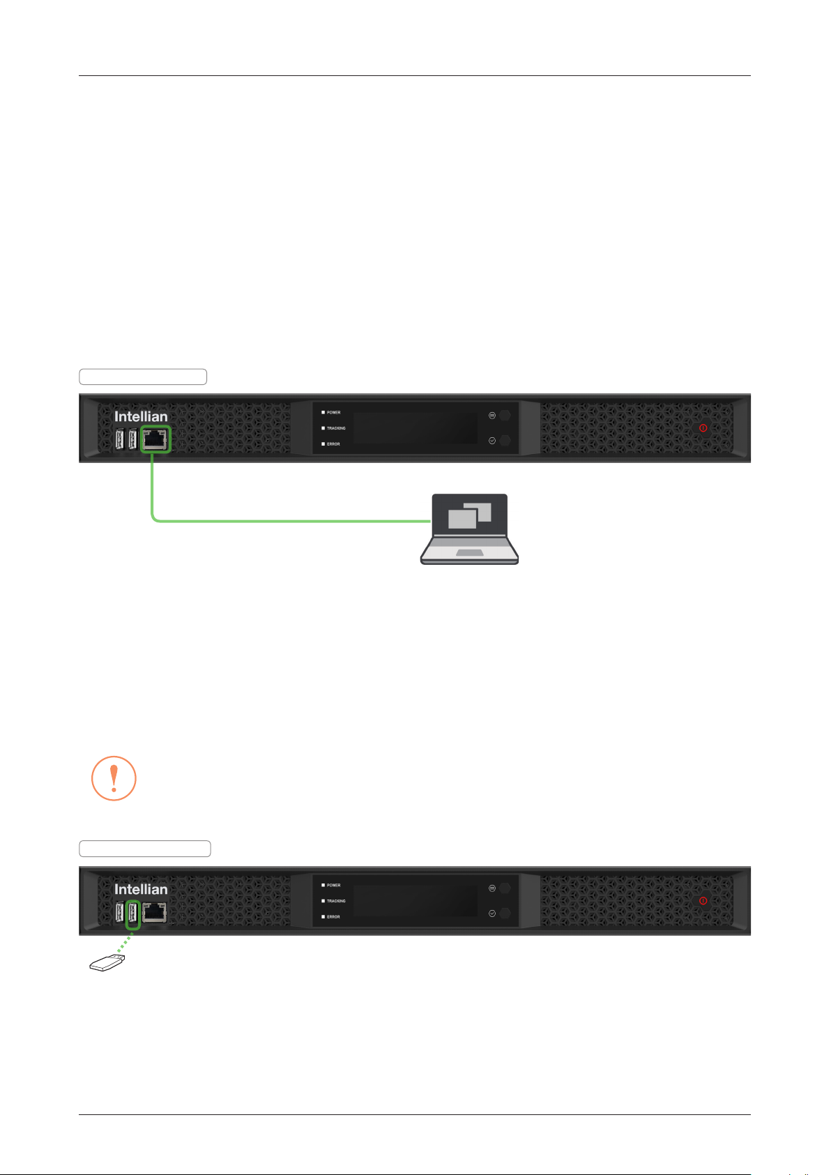
BDT to PC Communication Setup
You can establish data communication between the Below Deck Termial (BDT) and a PC the using one of the
following methods.
TCP/IP Connection
Connection through Front Panel Management Port
The network is automatically congured by DHCP without the need for additional PC IP conguration.
1. Connect an Ethernet cable from the Management LAN port on the front of the BDT to the LAN port of PC.
2. The network connection is established automatically.
3. Use the following IP address to access Intellian AptusNX page.
• IP Address: 192.168.2.1 (Default)
BDT - Front Panel
Management LAN Port
PC
(Not supplied)
Figure: Front Panel Management LAN Port Connection
USB Connection:
Connection through Front Panel Right USB Port
The "Right USB port" just allows the USB device to be connected to each other for log download, backup/
restore antenna settings, and rmware upgrade. The "Left USB port" is only for a service engineer.
CAUTION
Make sure that the USB is connected to the "Right USB port" to communicate with the antenna. Do
CAUTION
BDT - Front Panel
not connect to the "Left USB port".
Right USB port
Figure: Front Panel Right USB Port Connection
45

Installing Below Deck Unit (BDU)
Wi-Fi Dongle
Wi-Fi Connection
Connection through Rear Panel Wi-Fi Dongle
Intellian provides the Wi-Fi Dongle for Wi-Fi connection.
management and control whenever you are on the vessel.
1. Connect an Ethernet cable from the Management LAN port on the front of the BDT to the LAN port of PC.
The network connection is established automatically.
2. Bring the Wi-Fi Dongle located in the BDT package. Plug the Wi-Fi Dongle into the USB port on the rear
of the BDT.
Figure: Rear Panel Wi-Fi Dongle Connection
3. Use the following IP address to access Intellian AptusNX page.
• IP Address: 192.168.2.1 (Default)
4. Log into the AptusNX by typing in User Name and Password information. If this system has not been
changed from the factory default:
• User Name: intellian
• Password: 12345678
5. Select the "SETUP" on the
"
Wi-Fi Access Point Conguration
main menu then select the "Network" menu. Choose the AP "
". If you don't want to use Wi-Fi Connection, choose the AP "
button.
6. Check the "SSID (Wi-Fi AP Name)" information.
7. Choose the SSID Broadcast "
Enable
" button to show the SSID (Wi-Fi AP Name) on the Wi-Fi list.
8. Click the "Apply" button to apply the settings to the system. Then perform the "iARM Save & Reboot" on
page 93.
9. After rebooting, connect to the Wi-Fi.
You can connect to the BDT via Wi-Fi for easy
Enable
" button on the
Disable
"
1
2
3
4
5
6
46

Operating Install Wizard
Operating Install Wizard
Turning On System
Make sure the antenna has a clear view of the sky. Press the Power button on the front of the Below Deck
Termial (BDT) then a wait few minutes for system startup. Once the antenna nds the satellite, the "POWER"
status lights will be lit Green.
Accessing AptusNX
The network is automatically congured by DHCP without the need for additional PC IP conguration.
1. Connect an Ethernet cable from the Management LAN port on the front of the BDT to the LAN port of PC.
2. The network connection is established automatically.
3. Use the following IP address to access Intellian AptusNX page.
• IP Address: 192.168.2.1 (Default)
4. Log into the AptusNX by typing in User Name and Password information. If this system has not been
changed from the factory default:
• User Name: intellian
• Password: 12345678
BDT - Front Panel
Management LAN Port
PC
(Not supplied)
Figure: Front Panel Management LAN Port Connection
47

Operating Install Wizard
Starting Install Wizard
The Install Wizard will guide you through the steps of setting up the antenna system for commissioning. We
highly recommend using this wizard to complete your installation and commissioning the system. You can
choose to exit the wizard at any time by clicking the Finish button. You can also skip a step by clicking the
Next button. However, it is recommended to follow the procedure for the initial commissioning. Before you
start, please make sure the basic device connections (antenna, modem, etc) are connected to BDT properly.
This wizard includes a brief explanation of the purpose and action buttons to set the values. After accessing
the AptusNX main page, go to the "INSTALL WIZ." on the main menu then follow these steps.
NOTE
NOTE
The detailed description of each function is written on the
ü
Welcome Page
"Using AptusNX" chapter on page 80.
Description
Displays the welcome message. Click the
"Next" button to start.
ü
Step 1: Commissioning
Description
Performs the commissioning test to
calibrate the modem to receive the optimal
signal. The RF uplink frequency, the BUC
LO frequency, the TX frequency, and the
attenuator will calibrate automatically.
Click the 'Start' button to perform the
commissioning test automatically.
Ensure that the commissioning test is
performed after the rst-time connection
of the GX terminal, the BDT/cable
replacement, or band conversion.
If you have no problems, click the "Next"
button.
48

ü
Step 2: GPS
Operating Install Wizard
Description
Set the GPS position of the vessel for
searching for a satellite. Check the GPS
status connected to the antenna system.
The indicator right of the title shows the
GPS status. Please conrm the GPS
indicator is Blue (blinking).
• Blue (blinking): the system received a
correct GPS signal.
• Red: the GPS signal is abnormal or the
received value is incorrect (Error).
• Black: the system has not received a
GPS signal. You can enter the GPS
value manually to set the GPS position.
If you have no problems, click the "Next"
button.
ü
Step 3: Heading
Description
Set the ship's heading device. Choose
the device type from the "Current Device"
drop-down list. The indicator right of the
title shows the device connection status.
• Blue: a ship's heading device is
connected.
• Black: a ship's heading device is not
connected.
If you have no problems, click the "Next"
button.
49

Operating Install Wizard
ü
Step 4: Set Bow Offset
For setting bow offset, a trackable satellite must be selected. When Antenna tracks the selected satellite, the
bow offset will be set up automatically based on the GPS information.
Description
• Step 1: select a satellite in satellite
list then click the "Start Searching"
button.
Please wait until antenna terminal is
tracking the satellite. The bow offset will
be set up automatically.
• Step 2: check the "Lock On" mark and
click the "Save Satellite" button in the
"Bow Offset" menu to save the bow
offset information to BDT.
If you have no problems, click the "Next"
button.
ü
Step 5: Blockage
Description
It is important to set up the blockage
zones for Intellian VSAT. The BDT can
be programmed with relative azimuth
and elevation sectors to create up to
ve zones where transmit power could
endanger personnel who are frequently
in that area or blockage exists. The "AZ
Start" is where the relative azimuth starts
and the "AZ End" is where the relative
azimuth ends (Range: 0 ~ 360). The
"EL" is where the elevation block starts
(Range: 0 ~ 90).
If you have no problems, click the "Next"
button.
50

Operating Install Wizard
ü
Step 6: Target Satellite
Sets the target satellite that you want to track. There are two methods for selecting a target satellite.
NOTE
NOTE
The following images in this step show when the system is using the Open AMIP modem.
(Option 1: Using Controlled by Modem)
Description
This method is recommended.
The "Controlled by Modem" button on the
"Current Satellite" is selected and current
satellite information and NBD information
is displayed automatically.
If you have no problems, click the "Next"
button.
(Option 2: Using Manual Setup)
Description
When you did not set the modem
connection, select the "Manual Setup"
button and enter the satellite information
and NBD information manually to track a
satellite. Click the "Apply" button.
If you have no problems, click the "Next"
button.
51

ü
Step 7: Report
NOTE
Operating Install Wizard
NOTE
The following image in this step shows when the system is using the Open AMIP modem.
Description
Displays the conguration report. You can
save the results to the BDT by clicking the
"Save Report" button and download the
report le (.json) by clicking the "Export"
button.
Click the "View Last Report" button
to check the recently saved report
information including the save date and
time.
After completing the steps, click the
"Finish" button.
52

Operating BDT
Operating BDT
Introduction
Below Deck Termial (BDT)
The BDT has embedded Dual Antenna Mediator function, which is capable of controlling and managing two
VSAT antenna systems simultaneously in dual antenna system.
The Below Deck Termial (BDT) controls the various settings of the antenna.
Antenna System Type Target Antenna
Single Antenna System Controls and manages the antenna.
Dual Antenna System (optional) Controls and manages the primary antenna.
BDT Front Panel
The following gure shows the BDT's front panel.
Right USB Port:
For Log Data Download,
Backup/Restore Antenna Settings,
Firmware Upgrade
Management Port
Left USB Port:
Only for Service Engineer
The following table shows the function of each touch key.
Touch key Function
Power Button Power on/off the BDT.
Move Key Moves to the desired screen.
Select Key Selects the desired screen.
POWER Indicator
TRACKING Indicator
Figure: Name of BDT Front Panel
OLED Display
Move Key
Select Key Power ButtonERROR Indicator
The following table shows status indicators on the face of BDT.
LED Display Color Description
POWER
TRACKING Steady Green The antenna is in tracking mode.
ERROR Steady Red The antenna is faulty.
Steady Green The BDT is powered on.
Off The BDT is powered off.
53

BDT Display Menu
The following gure shows the BDT display menu.
32 541
SNR HDG:120.4
6
TRACKING 128.0 E
CM STS NET TX RX1 RX2
The following table shows the function of each touch key.
No. Item Description
1
Satellite Lock Displays the satellite lock status.
2
Signal Level Displays the antenna signal level.
3
Heading Information Displays heading information (e.g. gyrocompass).
4
GPS Lock Status Displays the GPS lock status.
Displays the antenna system status.
GPS:
8
Operating BDT
M U A P
7
Display Description
M
U
This function is available when using the Dual Antenna System.
Displays that the antenna system is in manual mode.
Displays that the antenna system is in progress rmware
upgrades.
This function is available when using the Dual Antenna System.
5
Antenna System Status
A
Displays the antenna's active state. The active antenna (either
primary or secondary antenna) is communicating (Tx/Rx) with
a target satellite.
• A (Active): the active antenna is displayed on the screen.
This function is available when using the Dual Antenna System.
Displays the antenna's role status.
P
• P: the BDT is connected to the primary role's antenna. The
primary antenna's role is to communicate with the target
satellite.
6
Antenna Status
7
Target Satellite Displays the target satellite (E: East, W: West).
Displays the antenna status (TRACKING, SEARCH 1, SEARCH 3, BEAM
S/W, BLOCKING).
54

No. Item Description
Below Deck Terminal (BDT) includes built in Satellite Modem.
Displays the modem status.
Item LED Display Description
CM
On
On
STS
Warning
On
8
Modem Indicator
NET
Abnormal
Off
On
TX
Abnormal
Off
On
RX1
Abnormal
Off
RX2
Abnormal
Off
Operating BDT
The modem is powered on.
The modem is in normal operating conditions.
The modem has a serious fault or failure in
software, hardware, or conguration.
The modem is connected to a target satellite and
acquired a network.
The modem network is in abnormal conditions.
The modem is not connected to a target satellite
and not acquired a network.
The modem Tx services are active.
The modem Tx is in abnormal conditions.
The modem Tx services are not active.
The modem Rx 1 services are active.
The modem Rx 1 is in abnormal conditions.
The modem Rx 1 services are not active.
The modem Rx 2 services are active.
The modem Rx 2 services are not active.
55

Operating BDT
Startup
With the system is installed and power is applied, the BDT display will show the following sequence.
Intellian XXXXXXX
ANTENNA INFO
EL INITIALIZE
AZ INITIALIZE
A P
SNR HDG:120.4
GPS:
SEARCH 1 128.0 E
CM STS NET TX RX1 RX2
ü Startup
("Intellian XX..." will appear. The "XX..." is the model name.)
ü
Initialize Antenna Information
ü
Initialize Elevation Angle
ü
Initialize Azimuth Angle
ü Antenna's Status
(in Search 1 (Global Search), Search 3 (Local Search),
Tracking, Beam Switching, Blocking)
A P
SNR HDG:120.4
GPS:
SEARCH 3 128.0 E
CM STS NET TX RX1 RX2
A P
SNR HDG:120.4
GPS:
TRACKING 128.0 E
CM STS NET TX RX1 RX2
A P
SNR HDG:120.4
GPS:
BEAM S/W 128.0 E
CM STS NET TX RX1 RX2
A P
SNR HDG:120.4
GPS:
BLOCKING 128.0 E
CM STS NET TX RX1 RX2
56

When the antenna is controlled by AptusNX, the BDT displays the control mode status.
Operating BDT
REBOOT
ANTENNA
SETUP MODE
TEST MODE
ONE TOUCH
COMMISSIONING
ü Control Mode Status
(in Reboot Mode, Setup Mode, Test Mode, One Touch
Commissioning)
If the antenna is not communicating with BDT, the "COMMUNICATION ERROR" message will appear.
COMMUNICATION
ERROR
57

Diagnosis
Executes antenna Diagnosis test and shows the real-time diagnosis result.
Operating BDT
A P
SNR HDG:120.4
GPS:
Move Key
TRACKING 128.0 E
Press
CM STS NET TX RX1 RX2
DIAGNOSIS
DIAG ALL
Press
Select Key
DIAG : CODE 101
1 - - - O O 7 O O 10
O O 13 14 O O
Refer to the diagnosis codes for the test results.
ü
Main Display
ü
Diagnosis Display
ü
Diagnosis Result Display
1
DIAG : CODE 101
1 - - - O O 7 O O 10
O O 13 14 O O
2
58

No. Item Description
Displays the diagnosis code.
Code Test
101 The data communication between the antenna and the
ACU is tested.
102 The azimuth axis is tested.
103 The elevation axis is tested.
104 The cross-level axis is tested.
105 Not Available
106 Not Available
1
Diagnosis Code
107 The rate sensor is tested.
108 Not Available
109 Not Available
110 The LNB / NBD is tested.
111 Not Available
112 Not Available
113 The antenna power is tested.
114 The ACU power is tested.
115 Not Available
116 The home sensor is tested.
Operating BDT
2
Diagnosis Result
• An example of diagnosis result:
1 - - - O O 7 O O 10
O O 13 14 O O
Diagnosis Result of Code 101~110
Diagnosis Result of Code 111~116
- ' - ' : The test was passed.
Code 102, 103, 104 and 111 were passed.
- Last 1 or 2 digits of diagnosis code : The test was failed.
Code 101, 107, 110, 113 and 114 were failed.
- ' O ' : The test was not performed.
Code 105, 106, 108, 109, 111, 112, 115 and 116 were not performed.
59

Antenna Information
Displays the Antenna/BDT serial number, PCU/STAB/BDT/iARM Version of the product.
Press
A P
SNR HDG:120.4
TRACKING 128.0 E
CM STS NET TX RX1 RX2
DIAGNOSIS
PRODUCT : XXXXXXX
ANT: xxxxxxxxx VER 1.00/1.00
ACU: xxxxxxxxxxxxx VER 1.00/1.00
GPS:
DIAG ALL
Move Key
Press
Move Key
ü
Main Display
ü
Diagnosis Display
ü
Antenna Information Display
(The "XX..." is the model name, and the "xxxx..." is
antenna/ACU serial number. )
Operating BDT
Refer to the Antenna Information display.
21
PRODUCT : XXXXXXX
ANT: xxxxxxxxx VER 1.00/1.00
ACU: xxxxxxxxxxxxx VER 1.00/1.00
3 4
No. Item Description
1
Antenna Serial Number
PCU Version/
2
STAB Version
3
ACU Serial Number
ACU Version/
4
iARM Version
Displays the Antenna serial number. The serial number is displayed
depending on the product.
Displays the PCU version, Stabilizer version.
Displays the ACU (BDT) serial number. The serial number is displayed
depending on the product.
Displays the ACU Main rmware version, iARM version.
60

Interface Information
Displays the modem/heading type in use and the network connection status.
Operating BDT
A P
SNR HDG:120.4
GPS:
TRACKING 128.0 E
CM STS NET TX RX1 RX2
DIAGNOSIS
DIAG ALL
PRODUCT : XXXXXXX
ANT: xxxxxxxxx VER 1.00/1.00
ACU: xxxxxxxxxxxxx VER 1.00/1.00
INTERFACE
MODEM: IDIRECT-AMIP
HEADING: NONE NETWORK: 1-3-
Press
Move Key
Press
Move Key
Press
Move Key
ü
Main Display
ü
Diagnosis Display
ü
Antenna Information Display
(The "XX..." is the model name, and the "xxxx..." is
antenna/ACU serial number. )
ü
Interface Information Display
Refer to the Interface Information.
1
INTERFACE
MODEM: IDIRECT-AMIP
HEADING: NONE NETWORK: 1-3-
2 3
No. Item Description
1
MODEM Displays the modem type in use. (IDIRECT-AMIP)
2
HEADING Displays the heading type in use (NONE, NMEA0183, STATIC, NMEA2000).
Displays the network connection status with the BDT.
3
NETWORK
• An example of network result: 1-3-
- ' - ' : the network is not connected.
- ' 1~4 ' : the number (1~4) of connected BDT port to network.
61

Operating BDT
USB Function
To use this function, a USB Memory Stick must be connected to the USB port (the right USB port on the fron
of the BDT). The USB Function supports the four menus (LOG DOWNLOAD, FIRMWARE UPLOAD, BACKUP
TO USB, RESTORE FROM USB). For detailed information about each function, refer to the next page.
A P
SNR HDG:120.4
GPS:
TRACKING 128.0 E
CM STS NET TX RX1 RX2
DIAGNOSIS
DIAG ALL
PRODUCT : XXXXXXX
ANT: xxxxxxxxx VER 1.00/1.00
ACU: xxxxxxxxxxxxx VER 1.00/1.00
INTERFACE
MODEM: IDIRECT-AMIP
HEADING: NONE NETWORK: 1-3-
Press
Move Key
Press
Move Key
Press
Move Key
Press
Move Key
ü
Main Display
ü
Diagnosis Display
ü
Antenna Information Display
(The "XX..." is the model name, and the "xxxx..." is
antenna/ACU serial number. )
ü
Interface Information Display
USB FUNCTION
USB SEL
USB FUNCTION
LOG DOWNLOAD FIRMWARE UPLOAD
BACKUP TO USB RESTORE FROM USB
BACK
Press
Select Key
ü
USB Function Display
ü
USB Function Menu Display
62

LOG DOWNLOAD
Downloads all data logs to the USB memory stick
Operating BDT
USB FUNCTION
LOG DOWNLOAD FIRMWARE UPLOAD
BACKUP TO USB RESTORE FROM USB
USB FUNCTION
LOG DOWNLOAD FIRMWARE UPLOAD
BACKUP TO USB RESTORE FROM USB
LOG DOWNLOAD
1 WEEK LOG 1 MONTH LOG
3 MONTHS LOG
LOG DOWNLOAD
1 WEEK LOG 1 MONTH LOG
3 MONTHS LOG
BACK
BACK
BACK
BACK
Press
Move Key
Press
Select Key
Press
Move Key
Press
Select Key
ü
USB Function Menu Display
ü
Log Download Menu Display
ü
Download Log File to USB
(Select one of three options: 1 WEEK LOG / 1
MONTH LOG / 3 MONTHS LOG)
LOG DOWNLOAD
1 WEEK LOG 1 MONTH LOG
3 MONTHS LOG
LOG DOWNLOAD
1 WEEK LOG 1 MONTH LOG
3 MONTHS LOG
LOG DOWNLOAD
BACK
BACK
90%
Press
Select Key
Press
Select Key
Download Process Display
ü
DO NOT TURN OFF!
If there is not enough space on the USB memory stick, the "NOT ENOUGH SPACE" message will appear.
LOG DOWNLOAD
BACK
NOT ENOUGH SPACE
NOTE
NOTE
When you want to return to the previous display, select the "BACK" option then press the "Select" key.
63

Operating BDT
FIRMWARE UPLOAD
To use Firmware Upload function, you must follow the folder structure guide to congure the folders properly.
It supports up to FAT32. The antenna system is upgraded with the FWP le in the designated folder of a USB
memory stick.
USB FUNCTION
LOG DOWNLOAD FIRMWARE UPLOAD
BACKUP TO USB RESTORE FROM USB
USB FUNCTION
LOG DOWNLOAD FIRMWARE UPLOAD
BACKUP TO USB RESTORE FROM USB
BACK
BACK
FIRMWARE UPGRADE
Press
Move Key
x2 times
Press
Select Key
GX100NX
GX100NX_190101_V1.01.fwp
ü
USB Function Menu Display
ü
Upgrade Firmware to Antenna System
If the rmware le does not match the le format, the "INVALID FILE FORMAT" message will appear.
INVALID
BACK
FILE FORMAT
If there is no rmware le on the USB memory stick, the "FILE NOT FOUND" message will appear.
FILE
BACK
NOT FOUND
NOTE
When you want to return to the previous display, select the "BACK" option then press the "Select" key.
NOTE
64

BACKUP TO USB
Backs up the antenna setting les to the USB.
Operating BDT
USB FUNCTION
LOG DOWNLOAD FIRMWARE UPLOAD
BACKUP TO USB RESTORE FROM USB
USB FUNCTION
LOG DOWNLOAD FIRMWARE UPLOAD
BACKUP TO USB RESTORE FROM USB
BACK
BACK
Move Key
x3 times
Press
Select Key
ü
USB Function Menu Display
BACKUP TO USB
Press
ü
Back
up Antenna Setting les t
o USB
DO NOT TURN OFF!
If there is not enough space on the USB memory stick, the "NOT ENOUGH SPACE" message will appear.
DATA BACKUP
BACK
NOT ENOUGH SPACE
NOTE
When you want to return to the previous display, select the "BACK" option then press the "Select" key.
NOTE
65

RESTORE FROM USB
Restores the antenna setting by using the setting les saved in USB.
Operating BDT
USB FUNCTION
LOG DOWNLOAD FIRMWARE UPLOAD
BACKUP TO USB RESTORE FROM USB
USB FUNCTION
LOG DOWNLOAD FIRMWARE UPLOAD
BACKUP TO USB RESTORE FROM USB
BACK
BACK
BACKUP TO USB
DO NOT TURN OFF!
NOTE
When you want to return to the previous display, select the "BACK" option then press the "Select" key.
NOTE
Press
Move Key
x4 times
Press
Select Key
ü
USB Function Menu Display
ü
Restore Antenna Setting les
66

Operating ACU (Optional)
Operating ACU (Optional)
Introduction
Antenna Control Unit (ACU)
To use the Dual Antenna System (optional), the antenna system needs an additional Secondary ACU and
antenna to support the Dual Antenna System operation.
The Antenna Control Unit (ACU) controls the various settings of the antenna.
Antenna System Type Target Antenna
Dual Antenna System (optional) Controls and manages the secondary antenna.
ACU Front Panel
The following gure shows the ACU's front panel.
Right USB Port:
For Log Data Download,
Backup/Restore Antenna Settings,
Firmware Upgrade
Management Port
Left USB Port:
Only for Service Engineer
The following table shows the function of each touch key.
Touch key Function
Power Button Power on/off the ACU.
Move Key Moves to the desired screen.
Select Key Selects the desired screen.
POWER Indicator
TRACKING Indicator
Figure: Name of ACU Front Panel
OLED Display
Move Key
Select Key Power ButtonERROR Indicator
The following table shows status indicators on the face of ACU.
LED Display Color Description
POWER
ERROR Steady Red The antenna is faulty.
TRACKING Steady Green The antenna is in tracking mode.
Steady Green The ACU is powered on.
Off The ACU is powered off.
67

ACU Display Menu
The following gure shows the ACU display menu.
SNR F:20.119/18.250 RX:L TX:R
5
TRACKING 128.0 E
HDG:120.4 GPS: M U A S
Operating ACU (Optional)
32 41
6
7 8
The following table shows the function of each touch key.
No. Item Description
1
Satellite Lock Displays the satellite lock status.
2
Signal Level Displays the antenna signal level.
Frequency Information
3
(Target/LNB Local)
4
Polarization
5
Antenna Status Displays the antenna status (TRACKING, SEARCH).
6
Target Satellite Displays the target satellite (E: East, W: West).
7
Heading Information Displays heading information (e.g. gyrocompass).
8
GPS Lock Displays the GPS lock status.
Displays the frequency information (Target, LNB Local).
Displays the Rx/Tx polarization (H: Horizontal, V: Vertical, L: LHCP, R:
RHCP).
Displays the antenna system status.
Display Description
M
U
This function is available when using the Dual Antenna System.
Displays that the antenna system is in manual mode.
Displays that the antenna system is in progress rmware
upgrades.
This function is available when using the Dual Antenna System.
Displays the antenna's active state. The active antenna (either
9
Antenna System Status
A
primary or secondary antenna) is communicating (Tx/Rx) with
a target satellite.
• A (Active): the active antenna is displayed on the screen.
This function is available when using the Dual Antenna System.
Displays the antenna's role status.
• S (Secondary): the ACU is connected to the secondary
S
role's antenna. The secondary antenna's role is on standby
and ready to assume primary antenna role to provide better
service in the event of tracking failure or low signal level
status.
9
68

Operating ACU (Optional)
Startup
With the system is installed and power is applied, the ACU display will show the following sequence.
Intellian XXXXXXX
ANTENNA INFO
EL INITIALIZE
AZ INITIALIZE
SNR F:20.119/18.250 RX:L TX:R
SEARCH 1 128.0 E
HDG:120.4
GPS:
A S
ü Startup
("Intellian XX..." will appear. The "XX..." is the model name.)
ü
Initialize Antenna Information
ü
Initialize Elevation Angle
ü
Initialize Azimuth Angle
ü Antenna's Status
(in Search 1 (Global Search), Search 3 (Local Search),
Tracking, Beam Switching, Blocking)
SNR F:20.119/18.250 RX:L TX:R
SEARCH 3 128.0 E
HDG:120.4
SNR F:20.119/18.250 RX:L TX:R
GPS:
A S
TRACKING 128.0 E
HDG:120.4
SNR F:20.119/18.250 RX:L TX:R
GPS:
A S
BEAM S/W 128.0 E
HDG:120.4
SNR F:20.119/18.250 RX:L TX:R
GPS:
A S
BLOCKING 128.0 E
HDG:120.4
GPS:
A S
69

Operating ACU (Optional)
When the antenna is controlled by AptusNX, the ACU displays the control mode status.
REBOOT
ANTENNA
ü Control Mode Status
(in Reboot Mode, Setup Mode, Test Mode)
SETUP MODE
TEST MODE
If the antenna is not communicating with ACU, the "COMMUNICATION ERROR" message will appear.
COMMUNICATION
ERROR
70

Diagnosis
Executes antenna Diagnosis test and shows the real-time diagnosis result.
Operating ACU (Optional)
SNR F:20.119/18.250 RX:L TX:R
TRACKING 128.0 E
HDG:120.4
GPS:
A S
DIAGNOSIS
DIAG ALL
DIAG : CODE 101
1 - - - O O 7 O O 10
- O 13 14 O O
Press
Move Key
Press
Select Key
ü
Main Display
ü
Diagnosis Display
ü
Diagnosis Result Display
Refer to the diagnosis codes for the test results.
1
DIAG : CODE 101
1 - - - O O 7 O O 10
- O 13 14 O O
2
71

No. Item Description
Displays the diagnosis code.
Code Test
101 The data communication between the antenna and the
ACU is tested.
102 The azimuth axis is tested.
103 The elevation axis is tested.
104 The cross-level axis is tested.
105 Not Available
106 Not Available
1
Diagnosis Code
107 The rate sensor is tested.
108 Not Available
109 Not Available
110 The LNB / NBD is tested.
111 The LNB pol motor is tested.
112 Not Available
113 The antenna power is tested.
114 The ACU power is tested.
115 Not Available
116 The home sensor is tested.
Operating ACU (Optional)
2
Diagnosis Result
• An example of diagnosis result:
1 - - - O O 7 O O 10
- O 13 14 O O
Diagnosis Result of Code 101~110
Diagnosis Result of Code 111~116
- ' - ' : The test was passed.
Code 102, 103, 104 and 111 were passed.
- Last 1 or 2 digits of diagnosis code : The test was failed.
Code 101, 107, 110, 113 and 114 were failed.
- ' O ' : The test was not performed.
Code 105, 106, 108, 109, 112, 115 and 116 were not performed.
72

Antenna Information
Displays the Antenna/ACU serial number, PCU/STAB/ACU/iARM Version of the product.
Operating ACU (Optional)
SNR F:20.119/18.250 RX:L TX:R
TRACKING 128.0 E
HDG:120.4
GPS:
A S
DIAGNOSIS
DIAG ALL
PRODUCT : XXXXXXX
ANT: V0918070001 VER 1.00/1.00
ACU: V0918070001 VER 1.00/1.00
Refer to the Antenna Information display.
21
Press
Move Key
Press
Move Key
ü
Main Display
ü
Diagnosis Display
ü
Antenna Information Display
(The "XX..." is the model name, and the "xxxx..." is
antenna/ACU serial number. )
PRODUCT : XXXXXXX
ANT: V0918070001 VER 1.00/1.00
ACU: V0918070001 VER 1.00/1.00
3 4
No. Item Description
1
Antenna Serial Number
PCU Version/
2
STAB Version
3
ACU Serial Number
ACU Version/
4
iARM Version
Displays the Antenna serial number. The serial number is displayed
depending on the product.
Displays the PCU version / Stabilizer version.
Displays the ACU serial number. The serial number is displayed depending
on the product.
Displays the ACU version / iARM version.
73

Interface Information
Displays the modem/heading type in use and the network connection status.
Operating ACU (Optional)
SNR F:20.119/18.250 RX:L TX:R
TRACKING 128.0 E
HDG:120.4
GPS:
A S
DIAGNOSIS
DIAG ALL
PRODUCT : XXXXXXX
ANT: V0918070001 VER 1.00/1.00
ACU: V0918070001 VER 1.00/1.00
INTERFACE
MODEM: IDIRECT-AMIP
HEADING: NONE NETWORK: 1-3-
Press
Move Key
Press
Move Key
Press
Move Key
ü
Main Display
ü
Diagnosis Display
ü
Antenna Information Display
(The "XX..." is the model name, and the "xxxx..." is
antenna/ACU serial number. )
ü
Interface Information Display
Refer to the Interface Information.
1
INTERFACE
MODEM: IDIRECT-AMIP
HEADING: NONE NETWORK: 1-3-
2 3
No. Item Description
1
MODEM Displays the modem type in use. (IDIRECT-AMIP)
2
HEADING Displays the heading type in use (NONE, NMEA0183, STATIC, NMEA2000).
Displays the network connection status with the ACU.
3
NETWORK
• An example of network result: 1-3-
- ' - ' : the network is not connected.
- ' 1~4 ' : the number (1~4) of connected ACU port to network.
74

Operating ACU (Optional)
USB Function
To use this function, a USB Memory Stick must be connected to the USB port (the right USB port on the front
of the ACU). The USB Function supports the four menus (LOG DOWNLOAD, FIRMWARE UPLOAD, BACKUP
TO USB, RESTORE FROM USB). For detailed information about each function, refer to the next page.
SNR F:20.119/18.250 RX:L TX:R
TRACKING 128.0 E
HDG:120.4
GPS:
A S
DIAGNOSIS
DIAG ALL
PRODUCT : XXXXXXX
ANT: V0918070001 VER 1.00/1.00
ACU: V0918070001 VER 1.00/1.00
INTERFACE
MODEM: IDIRECT-AMIP
HEADING: NONE NETWORK: 1-3-
Press
Move Key
Press
Move Key
Press
Move Key
Press
Move Key
ü
Main Display
ü
Diagnosis Display
ü
Antenna Information Display
(The "XX..." is the model name, and the "xxxx..." is
antenna/ACU serial number. )
ü
Interface Information Display
USB FUNCTION
USB SEL
USB FUNCTION
LOG DOWNLOAD FIRMWARE UPLOAD
BACKUP TO USB RESTORE FROM USB
BACK
Press
Select Key
ü
USB Function Display
ü
USB Function Menu Display
75

LOG DOWNLOAD
Downloads all data logs to the USB memory stick
Operating ACU (Optional)
USB FUNCTION
LOG DOWNLOAD FIRMWARE UPLOAD
BACKUP TO USB RESTORE FROM USB
USB FUNCTION
LOG DOWNLOAD FIRMWARE UPLOAD
BACKUP TO USB RESTORE FROM USB
LOG DOWNLOAD
1 WEEK LOG 1 MONTH LOG
3 MONTHS LOG
LOG DOWNLOAD
1 WEEK LOG 1 MONTH LOG
3 MONTHS LOG
BACK
BACK
BACK
BACK
Press
Move Key
Press
Select Key
Press
Move Key
Press
Select Key
ü
USB Function Menu Display
ü
Log Download Menu Display
ü
Download Log File to USB
(Select one of three options: 1 WEEK LOG / 1
MONTH LOG / 3 MONTHS LOG)
LOG DOWNLOAD
1 WEEK LOG 1 MONTH LOG
3 MONTHS LOG
LOG DOWNLOAD
1 WEEK LOG 1 MONTH LOG
3 MONTHS LOG
LOG DOWNLOAD
BACK
BACK
90%
Press
Select Key
Press
Select Key
Download Process Display
ü
DO NOT TURN OFF!
If there is not enough space on the USB memory stick, the "NOT ENOUGH SPACE" message will appear.
LOG DOWNLOAD
BACK
NOT ENOUGH SPACE
NOTE
NOTE
When you want to return to the previous display, select the "BACK" option then press the "Select" key.
76

Operating ACU (Optional)
FIRMWARE UPLOAD
To use Firmware Upload function, you must follow the folder structure guide to congure the folders properly.
It supports up to FAT32. The antenna system is upgraded with the FWP le in the designated folder of a USB
memory stick.
USB FUNCTION
LOG DOWNLOAD FIRMWARE UPLOAD
BACKUP TO USB RESTORE FROM USB
USB FUNCTION
LOG DOWNLOAD FIRMWARE UPLOAD
BACKUP TO USB RESTORE FROM USB
BACK
BACK
FIRMWARE UPGRADE
Press
Move Key
x2 times
Press
Select Key
GX100NX
GX100NX_190101_V1.01.fwp
ü
USB Function Menu Display
ü
Upgrade Firmware to Antenna System
If the rmware le does not match the le format, the "INVALID FILE FORMAT" message will appear.
INVALID
BACK
FILE FORMAT
If there is no rmware le on the USB memory stick, the "FILE NOT FOUND" message will appear.
FILE
BACK
NOT FOUND
NOTE
When you want to return to the previous display, select the "BACK" option then press the "Select" key.
NOTE
77

BACKUP TO USB
Backs up the antenna setting les to the USB.
Operating ACU (Optional)
USB FUNCTION
LOG DOWNLOAD FIRMWARE UPLOAD
BACKUP TO USB RESTORE FROM USB
USB FUNCTION
LOG DOWNLOAD FIRMWARE UPLOAD
BACKUP TO USB RESTORE FROM USB
BACK
BACK
Move Key
x3 times
Press
Select Key
ü
USB Function Menu Display
BACKUP TO USB
Press
DO NOT TURN OFF!
Press
Select Key
up Antenna Setting les t
o USB
ü
Back
If there is not enough space on the USB memory stick, the "NOT ENOUGH SPACE" message will appear.
DATA BACKUP
BACK
NOT ENOUGH SPACE
NOTE
When you want to return to the previous display, select the "BACK" option then press the "Select" key.
NOTE
78

RESTORE FROM USB
Restores the antenna setting by using the setting les saved in USB.
Operating ACU (Optional)
USB FUNCTION
LOG DOWNLOAD FIRMWARE UPLOAD
BACKUP TO USB RESTORE FROM USB
USB FUNCTION
LOG DOWNLOAD FIRMWARE UPLOAD
BACKUP TO USB RESTORE FROM USB
BACK
BACK
BACKUP TO USB
DO NOT TURN OFF!
NOTE
When you want to return to the previous display, select the "BACK" option then press the "Select" key.
NOTE
Press
Move Key
x4 times
Press
Select Key
ü
USB Function Menu Display
ü
Restore Antenna Setting les
79

Using AptusNX
Using AptusNX
Introduction
With embedded AptusNX software, the antenna can be monitored, controlled, and diagnosed remotely from
anywhere, anytime through TCP/IP protocol. This not only can save time but also save the cost generated from
the hundreds of routine maintenance activities such as operating rmware upgrades, tracking parameters resets,
and system Diagnosis.
How to access AptusNX for BDT
1. Connect an Ethernet cable from the Management LAN port on the front of the BDT to the LAN port of PC.
This method is most recommended.
2. Enter the BDT's IP address (192.168.2.1) into your web browser's address bar to login into the BDT's
internal HTML page, if this system has not been changed from the BDT's factory default.
NOTE
NOTE
AptusNX can be displayed on Internet Explorer 11 or later (Windows 7 or later), and is also compatible
with Firefox, Microsoft Edge and Chrome web browsers.
80

Using AptusNX
Main Page
Page Login
The Intellian software Aptus provides a different user level access to ensure safe operation of the system.
Depending on the user level, a limited range or a full range of functions can be accessed and operational.
1. Log into the BDT by typing in User Name and Password information. If this system has not been changed
from the factory default:
User Type User ID Password Access Authority
intellian 12345678 Supports all menus for monitoring and setting.
Admin
captain 12345678
User guest guest
Supports all menus for monitoring and setting.
Can control and manage user permission separately.
Only some menus for monitoring are supported.
(Dashboard, Tools, Troubleshooting)
NOTE
NOTE
After entering with the default password, the user must change the default password to a new password
for security.
81

Top Menus
Once you log in, the following information and menus are displayed.
Using AptusNX
1 3
7
2
No. Item Description
1
Target Satellite Displays the name of the targeted satellite.
When clicking this top menu area (marked as red dots), the
"Quick Status Screen" appears. You can quickly monitor
each status of the four items (Enable Mode, Blockage,
Pointing, Modem Lock) through the screen (Blue: enable,
2
Quick Status
Screen Area
Black: disable).
Displays the antenna status through a yellow indicator in the SETUP mode.
Antenna Status
3
Info
• Initialize: the antenna system is initialized.
• Searching: the antenna is searching the target satellite.
• Tracking: the antenna is tracking the target satellite.
4
Signal Level Displays the current signal level.
5
Tx Status Displays whether or not the antenna is able to transmit data.
6
Lock Displays whether or not the satellite is locked.
7
Main Menu
Selects the Main Menu (DASHBOARD, INSTALL WIZ, TOOLS, TROUBLESHOOTING,
SETUP). Each main menu offers side menus on the left of the screen.
Enters the setup mode to modify settings. The following functions are available
only in setup mode.
4
8 9 1110 12 13
<Quick Status Screen>
5 6
Main Menu Side Menu Function
SETUP Antenna Antenna Angle
8
Setup
Backup & Restore Setting Antenna Restore
9
Restart Restarts the antenna system.
10
Reboot
11
Save Sat. Saves bow offset.
12
Ant. Info Obtains current antenna information.
Reboots the antenna system to become the normal mode when operating in
Setup mode.
Select the "Account" button and enter the user management menu. The "Account"
13
Account Button
and the "Logout" menu will appear. Select the "Account" menu to manage your
account details and select the "Logout" menu to log out of the AptusNX web
page.
Dish Scan Range Check
Sensor Calibration
• Tilt Sensor Bias
• Rate Sensor Bias
Antenna Mode
• Set Idle Mode
82

Account Menu
Using AptusNX
1. Select the "Account"
button
and enter the user management menu.
2. The "Account", "System", "User Mgr.", and "Logout" menu option
options to manage or control details, or sele
ct t
he "Logout" menu to log out of the AptusNX web page.
Account
1
2
s wi
ll appear. Select one of t
he f
irst three
1
2
3
No. Item Description
1
Account Updates your password and sets timeout.
You can change your password.
• Current User ID: displays your user ID.
• User ID: enter the current user ID.
• Current Password: enter the current password.
• New Password: enter the new password.
• Conrm New Password: re-enter the new password to verify that it was entered
2
Change
Password
correctly.
Click the "Change Password" button to change to the new password. At the next
login, the new password is required.
You can set guest connection and timeout.
• Allow Guest Connections: sets up the guest access option (Disable / Enable).
3
Session
• Idle Session Timeout: sets the Idle timeout.
• Console Timeout: sets the console timeout.
Click the "Apply" button to apply the settings to the system.
83

Registration
1
Using AptusNX
2
3
4
V5-85-U1JW
V0918070001
No. Item Description
1
Registration
Enters product registration information for the convenient use of a product. Click
the "Register (Update)" button to apply the settings to the system.
Displays the antenna information.
2
Product
• Antenna: displays the antenna name.
• Serial Number: displays the antenna serial number.
Enters the vessel information. There are two options whether using the IMO
number or not. When you have the IMO number select the "Yes" button and enter
3
Vessel
the IMO Number. When you do not have the IMO number select the "No" button
and enter the Ship Name, Type, and Owner information.
• Has IMO Number: selects whether using the IMO number or not.
• IMO Number: enters the IMO number.
4
Service Provider
Enters the service provider information.
• Service Provider 1/2/3: enters the name of the service provider.
84

System
1
Using AptusNX
2
3
4
v1.00
v1.00
v1.00
v1.00
v1.00
v1.00
v1.00
v1.00
192.168.2.1
2019-04-08
No. Item Description
1
2
3
4
System
Antenna
Information
S/W Version
Information
Network
Information
Displays system information such as the antenna, S/W version, and network IP
address.
Displays antenna information.
Displays S/W version information.
Displays network information.
85

User Manager
Using AptusNX
3
1
2
Editable User Permissions Menu
No. Item Description
1
User Manager
The captain with admin permissions can control and manage user permissions
separately.
To add a new user, click the "Add User" button. The registration window will
2
Add User
appear in the pop-up window. Enter the new user ID and password then click the
"Add User" button.
Displays the user management state and can control and manage through the
control buttons.
• ID: displays the registered user ID.
• Description: displays the user's description.
User Management
3
List
• Controls: each user can be controlled and managed by individual settings.
- User Setting: reset the user ID by clicking the "Update User" button, and
changes the password by clicking the "Reset Password" button.
- Edit Menu Permission: choose user permissions by clicking the checkbox.
After selecting the options, click the "Apply" button. The user can only
access the selected menus.
- Delete User: deletes the user.
86

Using AptusNX
Dashboard
The Dashboard menu is displayed as below to provide quick monitoring of the antenna status. The Dashboard
helps you arrange panels on a single screen while providing you with a broad view of a variety of information at
once. The dashboard contains multiple panels, which can easily customize the structure of your dashboard and
arrange your panels in various ways to make them more readable and user-friendly.
NOTE
NOTE
NOTE
The measured temperature may
differ from the actual temperature.
How to Add & Remove Panels (Dashboard Setting)
Adding Panels
gear
1. On the right side of the page, you will see the
gear
icon.
2. C
heck the box of the panel that you wish to add to the dashboard.
3. Click the "Apply" button to apply the settings to the system.
4. Once the panel is added, it will be automatically placed at the bottom of the page.
2
icon to edit your dashboard. To start editing, click on the
1
3
87

Using AptusNX
Remov
1. On the right side of the page, you will see the
ing Panels
gear
icon indicated by the red mark.
gear
icon to edit your dashboard. To start editing, click on the
2. Uncheck the box of the panel that you wish to remove from the dashboard.
3. Click the "Apply" button to apply the settings to the system.
2
1
3
How to Arrange Dashboard Layout
You can customize the dashboard by rearranging panels as you wish.
1. Click and hold the left mouse button on a panel's title and then drag-and-drop in the desired position.
2. This time, the selected panel will be moved to the desired position. You can also move multiple panels into
a customized layout in the same manner.
88

Using AptusNX
How to Use Shortcut Settings
Each panel on the dashboard provides a shortcut function. Using the "Shortcut" button on right side of the
panel, you can easily access the detailed information and manage the each panel's settings.
1. Click the "Shortcut" button indicated by the red mark to open the setting page.
2. The setting page will appear on the individualized web page. You can check the detailed information and
quickly apply settings that you wish.
Install Wizard
The description of this menu is written on the previous page.
for more details.
89
Refer to the "Starting Install Wizard" on page 48

Using AptusNX
System Tools
This menu sets and displays the F/W Upgrade, iARM Upgrade, iARM Save&Reboot, Satellite Library, and Graph
function.
Firmware Upgrade
1
2
3
4
v1.00 v1.00
v1.00
v1.00
v1.00
v1.00
v1.00
v1.00
v1.00
v1.00
v1.00
No. Item Description
Firmware
1
Upgrade
2
Current Version
Displays current rmware versions and upgrades antenna rmware.
Displays current rmware versions (Antenna STABILIZER, Antenna PCU, ACU
Main, Library, Stacker, ACU Display)
Upgrades antenna rmware. The update may take a few minutes to complete.
The upload time may vary due to a variety of factors such as the speeds of your
network. Uploading an incorrect rmware le may cause serious damage to your
3
New F/W
Upgrade
antenna and BDT. Please check rmware version before uploading rmware.
• Upgrade Method: selects an upgrade method between "Manual Upgrade" or
"Auto Upgrade".
NOTE: when using the "Manual Upgrade" method, refer to the following "Antenna
Firmware Update (Manual Upgrade method) Procedures" page for more details.
Displays previous/latest rmware package versions and rollback rmware to
4
Rollback
previous/latest version. Other function cannot be operated while rollback is in
progress.
v1.00
v1.00
v1.00
v1.00
90

Using AptusNX
Antenna Firmware Upgrade (Manual Upgrade method) Procedures:
1. Choose "Manual Upgrade" from the pull-down menu of Upgrade Method. Browse and select the upgrade
package le to upload. Click on the "Upload" button to transfer the Firmware package le ("*.fwp") to
iARM module.
1
2
3
NOTE
When selecting the box "Ignore warnings during installation and force the installation to continue"
NOTE
before performing the upgrade, the warning messages do not appear during the upgrade.
2. The antenna rmware state will appear in the pop-up window. Check the current version and the new
version. Click the "Start Upgrade" button.
3. During the upgrade process, the window will display process status.
4. If the rmware is successfully upgraded, it will display as the "Success". Click the "Ok" button to close
the pop-up window.
91

iARM Upgrade
1
2
3
4
Using AptusNX
No. Item Description
1
iARM Upgrade Upgrades the rmware of iARM module.
Browse and select the iARM rmware le to upload and click "Start Upload"
button. The update may take a few minutes to complete. The upload time may
2
New iARM
Firmware
vary due to a variety of factors such as the speeds of your network. Uploading
an incorrect rmware le may cause serious damage to your antenna and BDT.
Please check rmware version before uploading rmware.
NOTE: refer to the following "iARM Upgrade Procedures" page for more details.
Displays current bootstrap and bootloader version.
3
Bootstrap/
Bootloader
• Bootstrap: displays the Bootstrap Version (Main, Factory Default).
• Bootloader: displays the Bootloader Version (Main, Factory Default, Active
Bootloader)
The BDT has three storage parts the Sys0, the Sys1 and the Factory Default.
Selects the desired storage part and click the "Activate" button. Then perform the
"iARM Save & Reboot" on page 93 to apply the settings to the system.
• Sys0: displays the Sys0 version.
• Sys1: displays the Sys1 version.
• Factory Default: displays the Factory Default version.
The "Current Active" displays activated storage part Information.
4
Kernel/File
System
• Current Active
- Current Package: displays the activated storage part's name (Sys0, Sys1
or Factory Default).
- Kernel, File System: displays the activated storage part's le version.
92

Using AptusNX
iARM Upgrade Procedures:
1. Browse and select the iARM rmware le (.tgz) that you wish to upgrade. Click on "Start Update" button
to update the iARM rmware. Wait until the page is loaded.
1
2
NOTE
When selecting the box "Ignore warnings during installation and force the installation to continue"
NOTE
before performing the upgrade, the warning messages do not appear during the upgrade.
2. Once the update starts, the update process will be displayed on the screen. It will take about two minutes
to complete the rmware upgrade.
WARNING
Do not turn off the device power if the rmware upgrade page is displayed. Failure to comply may
WARNING
lead to damage and/or malfunction of the system.
3. Once the upgrade is completed, the iARM module will automatically reboot in 10 seconds.
iARM Save & Reboot
1
No. Item Description
1
2
3
2
3
iARM Save &
Reboot
Save & Reboot
Reboot without
Saving
Saves settings to the BDT and reboot or reboot the system without saving.
Saves the modied settings, and reboots the iARM. All conguration changes
made will be saved in the BDT and effective upon reboot. Click the "Save &
Reboot" button.
Reboots the iARM without saving the modied settings. All conguration changes
made will be lost upon reboot. Click the "Reboot Only" button.
93

Satellite Library
2
1
4
5
6
Using AptusNX
3
No. Item Description
1
Satellite Library Sets the satellite library information.
Reads or manages satellite information from the library.
• Get Library from ACU: obtains satellite library le from the BDT.
2
Satellite List
• Get Library from PC: obtains the satellite library le from the PC.
• Save to PC (Download): saves the current library le to the PC.
• Save to ACU: saves the current library le to the BDT.
3
Satellite
Information
Select one of the satellites in the "Satellite List" then Click the "Load Satellite"
button to load the satellite information.
Displays selected satellite information.
• Satellite Name: displays the satellite name.
• Longitude(º): displays satellite orbit position.
4
Common
Information
• Skew Offset: this function is not available.
• Identify: displays the lock setting type (Modem Lock / DVB Lock) for satellite
tracking.
• Rx Polarization: displays the current RX polarization.
• Tx Polarization: displays the current TX polarization.
5
DVB Information This function is not available.
Displays NBD mode's tracking information.
6
NBD Information
• Frequency (kHz_IF): sets the tracking frequency.
• Bandwidth (kHz): sets the detection bandwidth.
• Base Local (MHz): sets the base local.
94

Graph
1
Using AptusNX
2
Multi Chart View
No. Item Description
1
Graph
This view provides information on the Signal Level, EL Graph, AZ Absolute, AZ
Relative, Heading in the Multi Chart, Single Chart or AZ & EL formats.
Sets detailed options for the graph.
• Select Graph Item: shows the graphs of only the checked item(s) in the Multi
Chart, Single Chart or AZ & EL formats.
- Multi Chart: displays multiple graph Items in one graph View.
2
Graph
- Single Chart: displays the checked graph Item in each graph View.
- AZ & EL: displays the AZ / EL angle value in one graph View.
• Range(min): displays the data for the set time.
By clicking the "Clear" button, the existing displayed graph is cleared and a new
graph is displayed.
AZ & EL ViewSingle Chart View
95

Using AptusNX
System Troubleshooting
This menu sets and displays the Diagnosis, Antenna Log, Antenna Event Log and Support function.
Diagnosis
1
2
No. Item Description
1
Diagnosis Executes antenna diagnosis test to check the antenna status.
Select the checkbox (full diagnosis test or single diagnosis test) before modifying
the settings.
2
Diagnosis
• Select All: select to run a full diagnosis test.
• Clear Select: select to run a single diagnosis test.
• View Last Result: displays the recently saved diagnosis result.
• Start: executes the diagnosis test.
Diagnosis Procedures:
1. Select the checkbox (full diagnosis test or single diagnosis test) before modifying the settings. Click on the
"Start" button to run the diagnostic test.
2
1
96

Using AptusNX
2. Once the diagnosis starts, the page will indicate test status. It should take a few minutes to complete the
test.
3. After the diagnosis is completed the system shows the diagnosis results of each item. You can save the
results to the BDT by clicking the "Save Result" button and print this page by clicking the "Print" button.
To remove the result, click the "Clear Diagnosis" button.
4. When you want to check the recently saved diagnosis results, click the "View Last Report" button. The
pop-up page of the diagnosis results, including the save date and time, will appear. You can print this page
by clicking the "Print" button.
1
2
97

Antenna Log
1
2
3
4
No. Item Description
1
Antenna Log Displays the antenna log data.
2
GPS Log Option
Antenna Log
3
Download
4
Antenna F/W Log
Turns on/off the GPS log download option. Click the "Apply" button to apply the
settings to the system.
Any log data within three months can be downloaded. Select the duration on the
calendar view that you want to show. Then click the "Start Download" button.
NOTE: when selecting the box "Include Backup/Report File" before downloading,
the Backup/Report File will download together. When selecting the box "Compress"
before downloading, log les are downloaded in a compressed format.
Displays log information about rmware upgrade.
Using AptusNX
98

Antenna Event Log
Using AptusNX
1
2
3
No. Item Description
Antenna Event
1
Log
Displays the antenna system and user log information by setting urgency level.
Sets the log message option to display the event log.
• Severity: sets the urgency level.
• Category: sets the target that caused the message.
2
Query Filter
• Time Frame: sets the time limit that you want to show.
• Duration: sets the duration on the calendar view that you want to show.
• Tracking Method: sets the sorting type (Descending / Ascending).
Click the "Query Event Log" button to apply the settings to the system.
3
Event Log Displays event log information.
Support
2
1
No. Item Description
1
2
3
3
Support Supports the manual web page, support desk and FAQ list.
Shows the manual web page and support desk information.
Manual and Help
• View Manual: click the "View Manual" button to open the manual web page.
• Support Desk: click the "Support Desk" button to open Intellian's contact
details for support.
FAQ Provides answers to frequently asked questions about the product.
99

Using AptusNX
System Setting
This menu sets and displays the Ship, Antenna, Satellite, Network, Modem Info, SNMP, Backup & Restore and
Mediator function.
Ship Setting
1
2
3
4
5
No. Item Description
1
Ship Sets the ship information and block zone.
Sets the GPS position of the vessel for searching for a satellite. Check the GPS
status connected to the antenna system. The indicator left of the help button
shows the GPS status. Please conrm the GPS indicator is Blue (blinking). (Blue
(blinking): the system received a correct GPS input. Black: the system has not
2
GPS
received a GPS input. You can enter the GPS value manually to set the GPS
position.)
• Longitude(º): sets Longitude information (East / West).
• Latitude(º): sets Latitude information (North / South).
Click the "Apply" button to apply the settings to the system.
100
 Loading...