


Intellex DV16000 Digital Video Management
System
Installation and Operating Instructions
Version 3.1
Part Number 8200-0334-9900 A0

Installation and Operating Instructions
Notice
The information in this manual was current when published. The manufacturer reserves the right to revise
and improve its products. All specifications are therefore subject to change without notice.
Copyright
Under copyright laws, the contents of this manual may not be copied, photocopied, reproduced, translated
or reduced to any electronic medium or machine-readable form, in whole or in part, without prior written
consent of Sensormatic Electronics.
Trademarks
© Copyright 1997–2003 Sensormatic Electronics Corporation
Intellex® is a registered trademark of Sensormatic Electronics Corporation. IntelleCord™ and Smart
Search™ are trademarks of Sensormatic Electronics Corporation. Windows® is a registered trademark of
Microsoft Corporation. PS/2® is a registered trademark of International Business Machines Corporation.
®
Sony
is a registered trademark of Sony Corporation.
Trademarked names are used throughout this manual. Rather than place a symbol at each occurrence,
trademarked names are designated with initial capitalization. Inclusion or exclusion is not a judgment on the
validity or legal status of the term.
Video Systems Division
6795 Flanders Drive
San Diego, CA 92121-2903 U.S.A.
Thank you for using American Dynamics products. We support our products through an extensive
worldwide network of dealers. The dealer through whom you originally purchased this product is your point
of contact if you need service or support. Our dealers are empowered to provide the very best in customer
service and support. Dealers should contact American Dynamics at (800) 507-6268 or (561) 912-6259 or on
the Web at www.americandynamics.net.
ii
WARNINGS
Intellex DV16000 Digital Video Management System
WARNING: TO REDUCE RISK OF ELECTRIC SHOCK, DO NOT REMOVE COVER. NO USER
The lightning flash/arrowhead symbol, within an equilateral triangle, alerts the user to the presence of a
shock hazard within the product’s enclosure.
CAUTION: Danger of explosion if battery is incorrectly replaced.
Replace only with the same or equivalent type recommended by the battery manufacturer. Dispose of used
batteries according to the battery manufacturer’s instructions.
VORSICHT: ZUR VERMEIDUNG EINES STROMSCHLAGES DARF DAS GEHÄUSE NICHT ENTFERNT
ACHTUNG:Es besteht die Gefahr einer Explosion, wenn die Batterie nicht ordnungsgemäß
WARNING: THIS EQUIPMENT IS A CLASS 1 LASER PRODUCT INCORPORATING A CLASS 1 LASER
Rack Mounting
Consult with the supplier of your equipment rack for adequate rack mounting means, with proper
consideration for the weight of this product.
Consult with the manufacturer of your rack regarding the proper hardware and procedure of mounting this
product in a safe and useable fashion
Avoid uneven loading or mechanical instability when rack-mounting units.
Make sure that units are installed to get enough air flow for safe operation.
The maximum temperature for rack-mounted units is 40° C.
Avoid uneven loading or mechanical instability when rack-mounting units.
Check product label for power supply requirements to assure that no overloading of supply circuits or
overcurrent protection occurs.
Mains grounding must be reliable and uncompromised by any connections.
WARNING: THIS EQUIPMENT HAS BEEN TESTED AND FOUND TO COMPLY WITH THE LIMITS FOR
SERVICEABLE PARTS INSIDE. REFER SERVICING TO QUALIFIED SERVICE PERSONNEL.
DO NOT EXPOSE THIS APPLIANCE TO RAIN OR MOISTURE.
DO NOT INSTALL THIS PRODUCT IN HAZARDOUS AREAS WHERE HIGHLY
COMBUSTIBLE OR EXPLOSIVE PRODUCTS ARE STORED OR USED.
WERDEN. ES ENTHÄLT KEINE VOM BENUTZER ZU WARTENDEN TEILE. ÜBERLASSEN
SIE DIE WARTUNG NUR QUALIFIZIERTEM FACHPERSONAL.
ausgetauscht wird.
2
geprüfte
Sicherheit
DIODE AND IT COMPLIES WITH FDA RADIATION PERFORMANCE STANDARDS, 21 CFR
SUBCHAPTER J AND THE CANADIAN RADIATION EMITTING DEVICES ACT, REDR C1370.
A CLASS “A” DIGITAL DEVICE, PURSUANT TO PART 15 OF THE FCC RULES. THESE
LIMITS ARE DESIGNED TO PROVIDE REASONABLE PROTECTION AGAINST HARMFUL
INTERFERENCE WHEN THE EQUIPMENT IS OPERATED IN A COMMERCIAL
ENVIRONMENT. THIS EQUIPMENT GENERATES, USES AND CAN RADIATE RADIO
FREQUENCY ENERGY AND, IF NOT INSTALLED AND USED IN ACCORDANCE WITH THE
INSTRUCTION MANUAL, MAY CAUSE INTERFERENCE TO RADIO COMMUNICATIONS.
OPERATION OF THIS EQUIPMENT IN A RESIDENTIAL AREA IS LIKELY TO CAUSE
HARMFUL INTERFERENCE IN WHICH CASE THE USER WILL BE REQUIRED TO
CORRECT THE INTERFERENCE AT THEIR OWN EXPENSE.
N205
iii

Installation and Operating Instructions
Changes or modifications not expressly approved by the party responsible for compliance could void the
user’s authority to operate the equipment.
NOTE: This product was FCC verified under test conditions that included the use of shielded I/O cables
This digital apparatus does not exceed the Class A limits for radio noise emissions as set out in the Radio
Interference Regulations (ICES-003) of the Canadian Department of Communications.
Le présent appareil numérique n’émet pas de bruits radioélectriques dépassant les limites applicables de la
Classe A prescrites dans le Réglement (ICES-003) sur le brouillage radioélectrique édicté par le Ministère
des Communications du Canada.
and connectors between system components. To be in compliance with FCC regulations, the
user must use shielded cables and connectors for all except power and alarm cables.
iv

LICENSE INFORMATION
READ THIS LICENSE AGREEMENT BEFORE OPENING THE DISK PACKAGE, INSTALLING THE
SOFTWARE, OR USING YOUR SYSTEM.
THIS LICENSE AGREEMENT DEFINES YOUR RIGHTS AND OBLIGATIONS. BY BREAKING THE SEAL
ON THIS PACKAGE, INSTALLING THE SOFTWARE, OR USING YOUR SYSTEM, YOU AGREE TO ALL
OF THE TERMS AND CONDITIONS OF THIS AGREEMENT. IF YOU DO NOT AGREE TO ALL OF THE
TERMS AND CONDITIONS OF THIS AGREEMENT, YOU MAY, WITHIN 30 DAYS, RETURN THIS
PACKAGE, ALL THE DOCUMENTATION, AND ALL ACCOMPANYING MATERIAL(S) TO THE POINT OF
PURCHASE FOR A REFUND.
Software License
The Software includes the computer software, the associated media, any printed material, and any
electronic documentation and may be provided to you installed on a hard drive (the media) as part of a
system. The Software is licensed, not sold.
Grant of License
This agreement between Sensormatic and you permits you to use the Software you purchased. Once you
have purchased the number of copies you require, you may use the Software and accompanying material
provided you use no more than the licensed number of copies at one time. The Software is only licensed for
use with specified Sensormatic supplied equipment. If the Software is protected by a software or hardware
key or other device, the Software may be used on any computer where the key is installed. If the key locks
the Software to a particular System, the Software may only be used on that System.
Other Rights and Limitations
• A demonstration copy of the Software is considered purchased and is covered by this license
agreement.
• You may not de-compile, disassemble, reverse engineer, copy, transfer, or otherwise use the Software
except as stated in this agreement.
• The hardware/software key, where applicable, is your proof of license to exercise the rights granted
herein and must be retained by you.
• If the Software is provided as part of a System, the Software may only be used with the System.
• You may not sub-license, rent or lease the Software, but you may permanently transfer the Software to
another party by delivering the original disk and material comprising the Software package as well as
this license to the other party. Initial use of the Software and accompanying material by the new user
transfers the license to the new user and constitutes the new user’s acceptance of its terms and
conditions.
• Sensormatic reserves the right to revoke this agreement if you fail to comply with the terms and
conditions of this agreement. In such an event, you must destroy all copies of the Software, and all of its
component parts (e.g., documentation, hardware box, software key).
• The Software may contain software from third parties that is licensed under a separate End User
License Agreement (EULA). Read and retain any license documentation that may be included with the
Software. Compliance with the terms of any third party EULA is required as a condition of this
agreement.
Failure to comply with these restrictions will result in automatic termination of this license and will make
available to Sensormatic other legal remedies.
Upgrades
If the Software is an upgrade from another software version, you may use or transfer the Software only as
specified in this agreement. If the Software is an upgrade of a component of a package of Software
programs that you licensed as a single product, the Software may be used and transferred only as part of
that single product package and may not be separated for use on more than one computer.
Copyright
The Software is a proprietary product of Sensormatic and is protected by both the United States and
International copyright laws.
Intellex DV16000 Digital Video Management System
v

Installation and Operating Instructions
Limited Warranty
Sensormatic warrants that the recording medium on which the Software is recorded, and the documentation
provided with it, will be free of defects in materials and workmanship under normal use for a period of ninety
(90) days from the date of delivery to the first user. Sensormatic further warrants that for the same period,
the software provided on the recording medium under this license will substantially perform as described in
the user documentation provided with the product when used with the specified hardware.
Customer Remedies
Sensormatic’s entire liability and your exclusive remedy under this warranty will be, at Sensormatic’s option,
to a). attempt to correct software errors with efforts we believe suitable to the problem, b). replace at no cost
the recording medium, software or documentation with functional equivalents as applicable, or c). refund
the license fee and terminate this agreement. Any replacement item will be warranted for the remainder of
the original warranty period. No remedy is provided for failure of the diskette or Software if such failure is the
result of accident, abuse, alteration or misapplication. Warranty service or assistance is provided at the
original point of purchase.
No Other Warranties
The above warranty is in lieu of all other warranties, express or implied, including, but not limited to the
implied warranties of merchantability and fitness for a particular purpose. No oral or written information or
advice given by Sensormatic, its representatives, distributors or dealers shall create any other warranty,
and you may not rely on such information or advice.
No Liability For Consequential Damages
In no event will Sensormatic be liable to you for damages, including any loss of profits, loss of data or other
incidental or consequential damages arising out of your use of, or inability to use, the Software or its
documentation. This limitation will apply even if Sensormatic or an authorized representative has been
advised of the possibility of such damages. Further, Sensormatic does not warrant that the operation of the
Software will be uninterrupted or error free.
This limited warranty gives you specific legal rights. You may have other rights that vary from state to state.
Some states do not allow the exclusion of incidental or consequential damages, or the limitation on how
long an implied warranty lasts, so some of the above limitations may not apply to you.
General
If any provision of the agreement is found to be unlawful, void, or for any reason unenforceable, then that
provision shall be severed from this agreement and shall not affect the validity and enforceability of the
remaining provisions. This agreement is governed by the laws of the State of Florida.
You should retain proof of the license fee paid, including model number, serial number and date of payment,
and present such proof of payment when service or assistance covered by this warranty is requested.
U.S. Government Restricted Rights
The software and documentation are provided with RESTRICTED RIGHTS. Use, duplication, or disclosure
by the Government is subject to restrictions as set forth in subparagraph (c)(1)(ii) of the Rights in Technical
Data and Computer Software clause at DFARS 252.227-7013 or subparagraph (c)(1) and (2) of the
Commercial Computer Software—Restricted Rights at 48 CFR 52.227-19, as applicable. Manufacturer is
Sensormatic Corporation, 6600 Congress Avenue, Boca Raton, FL, 33431.
Important Information
Before proceeding, please read and observe all instructions and warnings contained in this manual. Retain
this manual with the original bill of sale for future reference and, if necessary, warranty service.
When unpacking your Intellex unit, check for missing or damaged items. If any item is missing, or if damage
is evident, DO NOT INSTALL OR OPERATE THIS PRODUCT. Contact Sensormatic or your dealer for
assistance.
For your Records
Complete the following product purchase information. The factory requests this information when contacted
for technical support. It is also valuable in case of loss or theft.
vi

Purchase Date: _______________________________________
Serial Number: ________________________________________
License Key
The Intellex 3.1 software is protected from unauthorized use by a software license key. This key matches
the electronic hardware of your system with the authorized software version and feature level of your
software to permit proper operation of your system. Any changes to the network adapter in your unit,
removal or modification of the license file, or replacement of the system disk will affect normal operation and
will require installation of a new license file. Please contact your authorized Sensormatic representative for
more information.
Intellex DV16000 Digital Video Management System
vii

Installation and Operating Instructions
viii

TABLE OF CONTENTS
Introduction ............................................................................................................................ 1
Features ............................................................................................................................................1
Basic Intellex System ......................................................................................................................4
Sample Network Configuration ...................................................................................................5
Option Packs ...................................................................................................................................6
Accessories ......................................................................................................................................7
Intellex USB Floppy Drive .....................................................................................................7
Intellex USB CD-RW Drive ....................................................................................................7
Intellex USB/RS-232 4-Port Expander .................................................................................7
Intellex Speakers .....................................................................................................................7
Call Monitor .............................................................................................................................7
Dome Control ..........................................................................................................................7
Installation .............................................................................................................................. 9
Finding a Location .......................................................................................................................10
Front Panel ....................................................................................................................................11
Rear Panel ......................................................................................................................................12
Required Connections .................................................................................................................15
Cameras In .............................................................................................................................15
Monitor ...................................................................................................................................15
Power Setting .........................................................................................................................15
Power In ..........................................................................................................................15
Mouse .....................................................................................................................................15
Optional Connections ..................................................................................................................16
Cameras Out ..........................................................................................................................16
Alarms ....................................................................................................................................16
Video Out ...............................................................................................................................16
Keyboard ................................................................................................................................16
Printer .....................................................................................................................................16
Com2 .......................................................................................................................................17
Video Out ...............................................................................................................................17
SCSI-3 ......................................................................................................................................17
Network ..................................................................................................................................17
Call Monitor ...........................................................................................................................18
System Setup ....................................................................................................................... 19
Starting the Intellex Unit .............................................................................................................20
Exiting to Windows .....................................................................................................................21
Regional Settings ..........................................................................................................................22
ix

Installation and Operating Instructions
Mouse Settings ..............................................................................................................................23
Time Zone Settings .......................................................................................................................24
Network Settings ..........................................................................................................................25
Configuring Computer Name and Workgroup or Domain in Windows 2000 ............25
Configuring the Computer Name and Workgroup or Domain .....................................25
Changing the Computer Name ....................................................................................25
Changing the Workgroup .............................................................................................26
Changing to a Domain ..................................................................................................26
Setting up Autologin ....................................................................................................................27
Configuring Intellex 3.1 for Dial-up Networking ....................................................................28
Configuring the Dial-Up Server ..........................................................................................28
Procedure for Forcing an Intellex modem to Disconnect ................................................29
Graceful disconnect .......................................................................................................29
Non-graceful disconnect ...............................................................................................29
Timed disconnect ...........................................................................................................29
Installing the ESM and converting to NTFS .............................................................................30
Printer Settings ..............................................................................................................................31
Language Setup ............................................................................................................................32
Shutting Down and Restarting System .....................................................................................33
Main Screen ......................................................................................................................... 35
On-screen Controls and Indicators .....................................................................................36
Setup Options ...................................................................................................................... 39
Setup Options Screen ...................................................................................................................40
Cameras Option ............................................................................................................................42
Names Tab ..............................................................................................................................42
Termination Tab ....................................................................................................................42
Gain Mode Tab ......................................................................................................................43
Camera Control Tab ..............................................................................................................43
Covert Mode Tab ...................................................................................................................45
Configuring a Covert Camera ......................................................................................45
Live Mode .......................................................................................................................45
Playback Mode ...............................................................................................................46
Exporting with a Covert Camera .................................................................................47
Status Screen ...................................................................................................................47
Schedule Option ...........................................................................................................................48
Use Regular Schedule ...........................................................................................................48
Quality Tab .....................................................................................................................49
Time Tab ..........................................................................................................................50
Cameras (1-8 and 9-16) Tabs ........................................................................................50
Regular Schedule Popup Menu ...................................................................................51
Copying and Pasting a Filter ........................................................................................52
x

Intellex DV16000 Digital Video Management System
Replacing a Filter ...........................................................................................................52
Deleting a Filter ..............................................................................................................52
Data Lifetime Tab ..........................................................................................................52
Use Custom Schedule ...........................................................................................................54
Time Tab ..........................................................................................................................55
Weekday/Weekend/Holiday Tabs ............................................................................57
Set Holidays Tab ............................................................................................................59
Data Lifetime Tab ..........................................................................................................60
Working with Schedule Segments ......................................................................................60
Defining a New Segment ..............................................................................................60
Changing a Segment ......................................................................................................61
Deleting a Segment ........................................................................................................61
Copying a Camera Schedule ........................................................................................62
Custom Schedule Popup Menu ..........................................................................................62
Configuring an Active Segment ..................................................................................66
Configuring an Alarmed Segment ..............................................................................68
Live Filter Configuration .....................................................................................................70
Motion Detection ...........................................................................................................70
Perimeter Protection ......................................................................................................72
Light Change ..................................................................................................................74
Motion Exception ...........................................................................................................76
What is Motion Exception? ..................................................................................................76
Active Zone Settings .............................................................................................................81
Size ...................................................................................................................................81
Speed ...............................................................................................................................81
Direction ..........................................................................................................................81
Testing .............................................................................................................................82
To use Motion Exception .....................................................................................................82
Environmental Factors .........................................................................................................84
Use Single Camera Schedule ...............................................................................................86
Single Camera Tab .........................................................................................................86
Data Lifetime Tab ..........................................................................................................87
Camera Selectable Rate Option ..................................................................................................88
Important Factors in Setting the Recording Rate .............................................................88
Recording Rate Descriptions ...............................................................................................89
Auto Rate Mode ....................................................................................................................90
Use Auto Rate Mode .....................................................................................................91
Camera Selectable Rate ........................................................................................... 91
Set Per Camera Rate Mode ...........................................................................................91
Image Rate Sliders .........................................................................................................92
Text Option ...................................................................................................................................94
Defining a Text Stream ........................................................................................................95
xi

Installation and Operating Instructions
Text Source Tab ..............................................................................................................95
Camera Associations Tab ..............................................................................................95
Adding a Text Stream ...........................................................................................................96
Editing a Text Stream ...........................................................................................................96
Deleting a Text Stream .........................................................................................................96
Advanced Text ..............................................................................................................................97
Advanced Text Criteria ........................................................................................................97
Transaction Definitions ......................................................................................................100
Alarms Tab ....................................................................................................................101
Perform an Advanced Text Search ...................................................................................101
Edit an Advanced Text Search ..........................................................................................102
Delete an Advanced Text Search ......................................................................................102
Save an Advanced Text Search .........................................................................................103
Load an Advanced Text Search .........................................................................................103
Audio Option ..............................................................................................................................104
Audio Mixer Tab .................................................................................................................104
Camera Associations Tab ...................................................................................................105
Security Option ...........................................................................................................................106
Enabling Security ................................................................................................................106
Classic Security .............................................................................................................107
Advanced Security .......................................................................................................107
Adding a New User ............................................................................................................108
Editing a User ......................................................................................................................110
Deleting a User ....................................................................................................................111
Enabling/Disabling Security .............................................................................................111
Record Mode Option .................................................................................................................113
Notify when _____% full ....................................................................................................114
Database Full .......................................................................................................................114
Unarchived Images ......................................................................................................115
Archived Images ..........................................................................................................115
Alarms Option ............................................................................................................................116
General Tab ..........................................................................................................................116
Alarm In Names Tab ..........................................................................................................118
Alarm In Polarity Tab .........................................................................................................118
Display Option ............................................................................................................................120
Mode Tab ..............................................................................................................................120
2x2, 3x3, and 4x4 Tabs ........................................................................................................121
Date/Time Option ......................................................................................................................123
Port Address Option ..................................................................................................................124
Storage Option ............................................................................................................................125
Add Volume .........................................................................................................................126
Archive Schedule Option ..........................................................................................................127
xii

Intellex DV16000 Digital Video Management System
Archive All ...........................................................................................................................127
Archive Schedule ................................................................................................................127
Time Tab ........................................................................................................................128
Weekday/Weekend/Holiday Tab ...................................................................................131
Live Operation .................................................................................................................... 133
Logging In ...................................................................................................................................134
Changing Users ..........................................................................................................................135
Controlling Image Display .......................................................................................................136
Screen Format ......................................................................................................................136
1x1 ..................................................................................................................................136
2x2 ..................................................................................................................................136
3x3 ..................................................................................................................................136
4x4 ..................................................................................................................................136
Image Area Popup Menu ...................................................................................................137
Switching to Menu/Full Screen .................................................................................138
Single Pane ....................................................................................................................138
Generating an Alarm ...................................................................................................138
Camera ..........................................................................................................................138
Mode ..............................................................................................................................138
Image Area Zoom ...............................................................................................................139
Full Screen Operation .........................................................................................................139
Camera Sequencing ............................................................................................................140
Live Monitor (Optional) .....................................................................................................140
Dome Controller (Optional) ..............................................................................................140
Dome Camera Control ................................................................................................141
Unit Schedule .......................................................................................................................142
Reviewing Unit Status ...............................................................................................................143
Utility Options ............................................................................................................................145
Begin Record ........................................................................................................................146
Activity Log .........................................................................................................................146
Creating an Activity Log ............................................................................................147
Generate Alarms .................................................................................................................148
Clear Latched .......................................................................................................................149
Erase CD-RW .......................................................................................................................149
Log Out .................................................................................................................................150
Shutdown .............................................................................................................................150
Restart ...................................................................................................................................150
Exit to System ......................................................................................................................151
About Intellex ......................................................................................................................151
Upgrade .........................................................................................................................152
Software Maintenance Identification ........................................................................152
xiii

Installation and Operating Instructions
Playback Operation ........................................................................................................... 153
Playback Screen ..........................................................................................................................154
Playback Controls and Indicators .....................................................................................156
Using Play/Pause .......................................................................................................................158
Multi-Camera Playback ......................................................................................................160
Right-click Pop-up Menu ...................................................................................................161
Switch ............................................................................................................................161
Switching Cameras .............................................................................................................162
Full Screen Operation .........................................................................................................163
Image Area Zoom ...............................................................................................................164
Playback with Text Display ...............................................................................................164
Audio ....................................................................................................................................165
Selective Export ..........................................................................................................................166
Export Directory ...........................................................................................................166
Playback Tools ............................................................................................................................168
Image Enhancement Tools .................................................................................................171
Bright/Contrast Tool ...................................................................................................171
Color/Light Tools ........................................................................................................172
Balance Light Tool .......................................................................................................173
Edge Detect Tool ..........................................................................................................173
Enhance Light Tool ......................................................................................................173
Noise Reduction Tool ..................................................................................................173
Sharpen Tool .................................................................................................................174
Sharpen More Tool ......................................................................................................174
Smooth Tool ..................................................................................................................174
Smooth More Tool .......................................................................................................174
Search Operation ...............................................................................................................175
Search Mode Screen ...................................................................................................................176
No Image Filters ..................................................................................................................176
Date/Time Tab .............................................................................................................177
Camera Tab ...................................................................................................................178
Alarm Tab .....................................................................................................................179
With Image Filters ...............................................................................................................180
Date/Time Tab .............................................................................................................180
Filters Tab ......................................................................................................................181
Search Filter Configuration ........................................................................................182
Text Streams .........................................................................................................................183
Date/Time Tab .............................................................................................................183
Text Streams Tab ..........................................................................................................184
Working with Search Results ...................................................................................................185
Sorting the Search Results ..................................................................................................185
xiv

Intellex DV16000 Digital Video Management System
Selecting a Segment to Review ..........................................................................................185
Alarm Operation ................................................................................................................. 187
Mechanical Alarms ....................................................................................................................188
Live Filter Events ................................................................................................................189
Video Loss Alarms ..............................................................................................................190
Generated Alarms ...............................................................................................................191
Alarm Groups ......................................................................................................................192
Alarm Review Screen ................................................................................................................193
Selecting a Segment to Review ..........................................................................................194
Alarm Connectors ......................................................................................................................195
Installation and Use of Accessories ................................................................................197
USB Floppy Drive-RDVFLP01 .................................................................................................198
USB CD-RW Drive-RDVCDRX01 ............................................................................................199
USB/RS-232 Single COM Port Adapter ..................................................................................200
USB/RS-232 4-Port Expander-RDVEXP01 .............................................................................201
Serial Interfaces and Text Recording .......................................................................................202
Internal COM ports .............................................................................................................202
Port Expanders ....................................................................................................................202
Port Assignments ................................................................................................................202
COM Port Assignments .....................................................................................................202
Connecting Text Sources ....................................................................................................203
Connecting the Data Source ..............................................................................................203
Verifying Data Recording ..................................................................................................204
Port Expander Indicators ...................................................................................................204
Speakers-RDVSPK01 .................................................................................................................205
Archive Operation ..............................................................................................................207
Archive Options Screen .............................................................................................................208
Back Up Images to Tape .....................................................................................................208
Back up While Recording ...........................................................................................209
Stop Recording and Back Up Now ...........................................................................210
Restore Images From Tape ................................................................................................212
Play Restored Images .........................................................................................................213
Format Tape .........................................................................................................................214
Recover Data from Tape ....................................................................................................214
Recovering from an Interruption .............................................................................................215
Interrupting the Backup .....................................................................................................215
Record Capacity ................................................................................................................. 217
Activity Levels ............................................................................................................................221
Technical Specifications ................................................................................................... 223
Programmable Settings .............................................................................................................224
xv

Installation and Operating Instructions
Video Format ..............................................................................................................................225
Video Level ..................................................................................................................................226
Alarm ............................................................................................................................................227
Display .........................................................................................................................................228
Record Options ...........................................................................................................................229
On-Screen Controls ....................................................................................................................230
Rear Panel Connectors ...............................................................................................................231
Components ...............................................................................................................................232
Power Supply ..............................................................................................................................233
Accessories ..................................................................................................................................234
Physical Characteristics .............................................................................................................235
Environmental Requirements ...................................................................................................236
Index ................................................................................................................................... 237
xvi
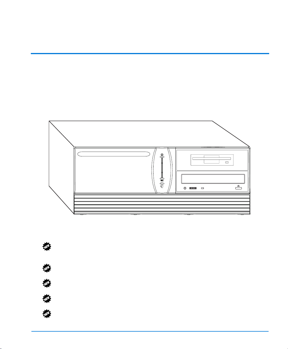
INTRODUCTION
The Intellex® DV16000 digital video management system combines multiplexing,
alarm/event detection, and records images from up to 16 video cameras. The images
are recorded directly to the internal hard drive which allows you quick and easy
access to your recorded images.
A variety of advanced, user-programmable features allow you to customize and
manage video data for your specific needs.
Figure 1 — Intellex
FEATURES
• The Activity Log provides a record of all activity that a user has performed on an
Intellex unit after the user has logged in, such as who changed a setting, which
menus were accessed, what video was downloaded, and so on.
• The Camera Selectable Rate feature lets you assign higher or lower recording rates
to specific cameras.
• The Covert Camera feature permits viewing and recording of video from specified
camera(s) by authorized users only.
• 15-Minute Index permits playback of video starting a full 15 minutes prior to the
actual alarm.
• Motion Exception permits filtering live video or searching recorded video for an
event or activity as defined by the size, direction, and speed of a moving object.
Introduction 1

Installation and Operating Instructions
• Dome Camera Controls let you adjust dome camera and lens settings. You can
control the camera’s pan and tilt movements; adjust its lens zoom, focus and iris
settings; use preset position settings for instant recall (if supported by the camera);
and select a pattern scan (if supported by the camera).
• Advanced Security provides both local and remote secured access to Intellex units
and to designated Intellex features (downloading and viewing video, setting up a
schedule, etc.) or resources (cameras, alarms, alarm list database, recorded video
database, etc.). Advanced Security requires that Policy Manager be installed on the
network to which Intellex is attached. Policy Manager enables an administrator to
manage secured access to Intellex units and to Network Client.
• Advanced Text search lets you define complex search criteria to find specific
events in a text stream when filtering live video or searching recorded video.
• Video segments can be exported to an optional CD-RW. You can mark the
beginning and end of video segments in Playback Mode to export.
• 320x240 lower resolution recording available, selected in the schedule dialog for
each camera. This resolution can also be selected for alarm recording.
• Enhanced triplex operation provides simultaneous record/display, playback and
archiving.
• Use SmartSearch filters to quickly search the image database for video segments
containing specific types of activity (see Search Operation on page 175).
• Ethernet 10/100 Network Interface allows remote access to video and setup
functions. Dial-up modem is optional.
• Use date and time, camera and alarm criteria to quickly search the image database.
Play back these video segments.
• Records and stores pre-alarm images according to each camera’s pre-alarm setting
(0 to 300 seconds).
• Compatible with color and B&W video cameras or other NTSC/EIA (PAL/CCIR)
standard compatible video sources. Video synchronization is not required.
• Records images digitally, which eliminates the need for VCRs and videotape.
Backs up images to an optional CD-RW or an optional Digital Audio Tape (DAT),
saves them to a floppy diskette or transfers them to videotape.
• User can select, enhance and copy images onto a computer diskette or print them.
• Multi-camera live displays are available for any camera in any position in the
following formats: 1x1, 2x2, 3x3 and 4x4. A full-screen view hides the controls and
fills the entire screen.
• Provides outstanding picture quality using a 640x480 pixel display (800x600 in
full-screen mode) with 256 gray levels and over 16 million colors.
• Offers seven record rates: NTSC — 120, 60, 30, 15, 7.5, 2.5 and 1 images per second
(ips); PAL — 100, 50, 25, 12.5, 6.25, 2 and 0.8 ips.
2 Introduction

Intellex DV16000 Digital Video Management System
• On-screen menus simplify system setup and operation.
• Online help information is available from every screen.
• One alarm input and one alarm output are available for each camera. The polarity
for each alarm input can be set to either active high or active low.
• A security system provides password protection to restrict access to various
operation and configuration functions.
• On-screen display includes date, time, alarm status, video loss and 10-character
camera titles.
• Hard disk storage protects all system configuration information against power
loss.
• Unit storage capacity can be increased by purchasing an additional optional
internal storage or an optional external data storage unit.
• An optional dome controller (Sensormatic VM16 or American Dynamics ADTT16)
can be used to select cameras, change display format to 1x1, 2x2, 3x3 or 4x4 and to
sequence cameras (live mode only).
• One to five Intellex units can be connected over a TCP/IP local area network
(LAN) or wide area network (WAN). The Network Client software must be installed
on your computer.
• Internal floppy drive added.
• Supports simultaneous and synchronized playback of up to 16 cameras.
Introduction 3
Installation and Operating Instructions
BASIC INTELLEX SYSTEM
A sample configuration is shown below.
Figure 2 — Basic Intellex System
4 Introduction

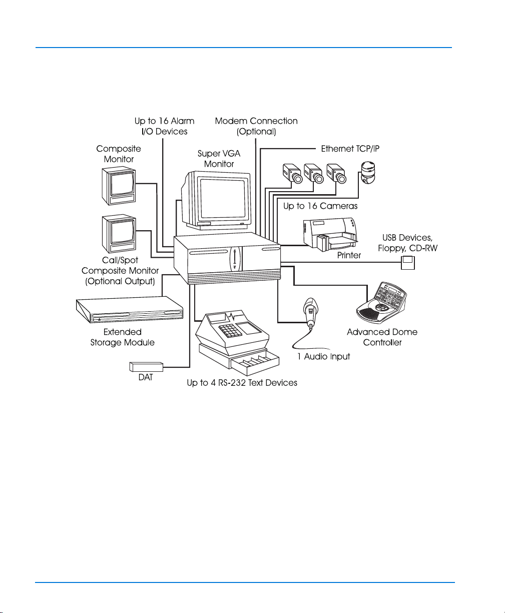
SAMPLE NETWORK CONFIGURATION
One or more Intellex units can be connected over a TCP/IP local area network (LAN)
or a wide area network (WAN). Its data can then be managed from a central site using
the Network Client (sold separately). A sample network configuration is shown below.
Intellex DV16000 Digital Video Management System
Figure 3 — Sample Network Configuration
Introduction 5

Installation and Operating Instructions
OPTION PACKS
There are two different option packs that are available to supplement your Intellex
DV16000. The following is a brief description of the Option Packs:
Data Pack Audio Enables the audio recording,
Tex t Enables the text recording, search,
Remote
Pack
Remote Setup Access Enables Network Client user to
Remote Smart Search Enables Network Client user to
Remote Text Search Enables Network Client user to
Remote Alarm
Generation
Alarm Message Display Enables display of the alarm message
playback, and download to Network
Client.
playback, and download to Network
Client.
access Setup functions in Intellex.
search the Intellex video image
database.
search recorded text streams for a
string.
Permits Network Client user to
generate an alarm on an Intellex
camera.
when viewing live video on Network
Client.
The Option packs are obtained by entering a software License Key for the specified
Option Pack.
6 Introduction

ACCESSORIES
Intellex USB Floppy Drive
The USB floppy drive can be used to save Intellex configurations, single .BMP images
from the image tools feature, and to install software patches and upgrades.
Intellex USB CD-RW Drive
The USB CD-RW drive can be used to export video clips to CD-R or CD-RW disks or
to update the Intellex software.
Intellex USB/RS-232 4-Port Expander
The 4-Port Expander can be used to add serial ports to the Intellex for the recording of
text data.
Intellex Speakers
The speakers can be used to listen to recorded audio information or to monitor live
audio activity.
Call Monitor
Intellex DV16000 Digital Video Management System
The Call Monitor board permits a single camera’s live (real-time) video signal to be
viewed on an additional video monitor (the Call Monitor board must be upgraded to
the fully populated version to support this option). This live display can be initiated
either by a command or by an alarm input in one of two modes: Call Mode or Spot
Mode. In Call Mode, video from a specific camera is displayed on the call monitor
when commanded by the user. In Spot Mode, the Intellex unit automatically displays
video in sequence from all alarmed cameras to the call monitor (similar to how a
multiplexer sequentially displays camera signals). The Call Monitor function can also
be controlled via a serial connection from a Touch Tracker controller.
Dome Control
Camera control can take place locally on the Intellex system, at the Touch Tracker, or
remotely at a Network Client workstation. Refer to the Network Client Installation and
Operating Instructions for details. Concurrent local and remote operation can cause
control conflicts. The camera will respond to the last control action performed,
whether that is at the Touch Tracker or at the Network Client. If another user tries to
control the same camera, unexpected actions of the camera may result.
Introduction 7

Installation and Operating Instructions
Use of the Touch Tracker version 2.x firmware can minimize control conflicts. This
firmware permits concurrent control of two different cameras connected to the same
Touch Tracker, one locally and one remotely. Conflicts can still occur if the same
camera is being controlled.
8 Introduction

The following is a list of the topics discussed in this chapter.
• Finding a Location
• Front Panel
• Rear Panel
• Required Connections
• Optional Connections
INSTALLATION
Installation 9

Installation and Operating Instructions
FINDING A LOCATION
Select a location for the Intellex unit that is clean and dry and where temperature and
humidity extremes do not exceed the product specifications (see Technical
Specifications on page 223). Failure to do so can result in equipment failure and loss of
warranty protection.
Make sure the location has stable AC power for the unit. Protect the unit against
severe power fluctuations by installing surge protection devices on all power cables.
10 Installation

FRONT PANEL
The following diagram shows the elements of the Intellex unit front panel. A
description of each numbered callout is given below.
Intellex DV16000 Digital Video Management System
1
2
3
4
4
5
6
Figure 4 — Front Panel
1. Power Indicator — This light appears when the unit is operating.
2. Power — Insert the special tool provided into this pinhole to turn unit power on
or off.
3. Reset — Insert special tool provided into this pinhole to reset the unit. The unit
powers up and performs its standard system diagnostics.
4. REC (Recording Indicator) — This light appears when the unit is recording
images to the image database.
5. Alarms Indicator — This light appears when alarm events have occurred, but
have not yet been reviewed. It also blinks when a notification screen appears.
6. Diskette Drive — Use this standard 1.44 MB, 3½-inch diskette drive to save and
restore individual images.
7. CD or Optional CD-RW — Standard CD can be used for software upgrades. If the
CD-RW option is purchased, video clips can be exported to a blank CD.
8. Front Panel Cover (not shown) — This hinged cover protects the CD, optional
CD-RW, or optional diskette drive.
7
Installation 11

Installation and Operating Instructions
REAR PANEL
The following diagram shows the elements of the Intellex unit rear panel. A
description of each numbered callout is given below
Figure 5 — Rear Panel Connectors
1. Power In — This connector accepts any AC main power cord with an
IEC-320-C13 plug. (Most standard computer cords meet this requirement.)
CAUTION: Before connecting power, set the voltage switch to the correct
voltage (“115” or “230”).
2. Power Setting — Use this switch to select the correct input voltage setting: 115 or
230 volts.
3. Mouse — This PS/2-style connector accepts the plug from the mouse (included
with unit) or any other PS/2-style input device.
4. Keyboard — An optional keyboard can be plugged into this PS/2-style connector.
NOTE: Adding a keyboard to the Intellex unit will provide access to certain operating
system features such as Log Off, Shutdown, and access to other applications.
This access is not controlled or limited by the Intellex Security Option. Do not
install a keyboard if you wish to restrict user access to these operating system
features.
5. USB Connectors — These connectors are used to add RS-232 ports, data storage
devices, and other accessories to the unit.
12 Installation

Intellex DV16000 Digital Video Management System
6. Printer — This DB25-S connector provides the interface between the unit and the
printer.
7. Com2 — This DB9-P connector provides the interface between the unit and a
dome controller (Sensormatic VM16 or American Dynamics ADTT16).
8. Network — This RJ-45 connector connects the unit to a local area network. The
unit supports 10BASE-T (10Mbps) and 100BASE-TX (100Mbps) network
operation.
9. Audio Connectors — These are 3.5mm audio jacks to connect audio
input/output.
Green Line Out (Speakers)
Blue Line In
Pink Mic In (Microphone)
10. S-VID OUT — This mini-DIN-7 connector provides an S-Video video signal to
display camera images and system status on an optional television or VCR. It
provides the same information as the VGA Monitor connector. A composite
monitor may be attached to this connector with the enclosed S-Video-to-RCA
adapter.
11. VGA OUT — This HD15-S VGA connector provides an SVGA signal to the Main
(SVGA) Monitor to display camera images and system status.
12. NOT USED.
NOTE: Even though an external SCSI terminator is not required on this unit, it may be
required on the optional data storage device.
13. SCSI-3 — This high density 68-pin female connector provides the interface
between the unit and an optional data storage device.
14. IEEE 1394 interface (FireWire) card — The optional 1394 interface card is
installed in this position. This connects to the optional Extended Storage Module
(ESM).
15. Video Out — This BNC connector provides a composite video signal of the live
display to an optional live monitor.
16. External Cable Connector — An external cable connects this IDC34 male header
connector to connector 23.
17. Video Out — This BNC connector provides a composite video signal of the Call
Monitor card to the optional call monitor.
18. External Cable Connector — An external cable connects this DB37-P female
connector to connector 22.
19. Modem card — The optional modem card is installed in this position. An RJ11
telephone jack connects to a standard analog telephone line connection.
20. Camera In — The left of each pair of BNC connectors inputs video. The
connectors accept the composite video output of color or B&W cameras.
Installation 13

Installation and Operating Instructions
21. Camera Out — The right of each pair of BNC connectors provides passive loop
through camera video from the corresponding camera input. Camera termination
is configured in the Cameras portion of the Setup Options screen. Therefore,
physical terminators are neither installed nor required.
22. External Cable Connector — An external cable connects this DB37-P female
connector to connector 18.
23. External Cable Connector — An external cable connects this IDC34 male header
connector to connector 16.
24. Alarms — These connectors accept up to 16 alarm inputs and 16 alarm outputs.
NOTE: The Time Sync Signal (Alarm In 17) is used to reset the system time of the
Intellex to the nearest hour. If the Intellex system time is up to 30 minutes
before the hour, the system time is set forward to the next hour (at zero
minutes and zero seconds). If the Intellex system time is up to 30 minutes
after the hour, the system time is set back to the previous hour (at zero
minutes and zero seconds).
NOTE: The Export Signal input (Alarm In 18) can be used to start a Fill CD operation
without access to the normal user interface. A contact closure, e.g., an
external switch, can be used to execute the Fill CD command to export the
last 500 MB of data to a CD. See Selective Export on page 166.
14 Installation

REQUIRED CONNECTIONS
CAUTION: Protect the unit against lightning. If a portion of a cable is installed
outside of a building, the entire cable is vulnerable to lightning.
Therefore, install surge protection devices on all vulnerable cables.
Cameras In
Connect the video output of each camera or other composite video source to its
corresponding Camera In connector (the left of each pair of BNC connectors). To use
the passive loop through feature, see Cameras Out on page 16.
Monitor
The monitor displays live and recorded cameras, as well as system configuration and
status information.
To connect the monitor:
1. Disconnect both ribbon cables from connectors 18 and 16 on the rear panel (see
Figure 5 — Rear Panel Connectors on page 12).
2. Connect the VGA cable from an SVGA monitor to the Monitor connector.
3. Reconnect both ribbon cables to connectors 18 and 16 on the rear panel.
Power Setting
Intellex DV16000 Digital Video Management System
CAUTION: Before connecting power, set the voltage switch to the correct
voltage (“115” or “230”).
Switch the power supply to the correct input voltage setting: 115 or 230 volts.
Power In
CAUTION: You may want to install power line conditioning equipment to protect
the unit against severe power fluctuations.
CAUTION: Do not apply power until you have connected all optional items.
Connect the power cable to the unit.
Mouse
Connect the mouse (or other pointing device) to the Mouse connector.
Installation 15

Installation and Operating Instructions
OPTIONAL CONNECTIONS
Cameras Out
The Camera Out connectors pass through the live video signal from the Camera In
connectors.
To add a loop-through device, connect the cable from the loop-through device to the
appropriate Camera Out connector. Then select Hi-Z for the camera in the Cameras
portion of the Setup Options screen.
To remove a loop-through device, disconnect the cable from the appropriate Camera
Out connector. Then select 75 Ohms termination for the camera in the Cameras
portion of the Setup Options screen.
Alarms
CAUTION: Protect the unit against lightning. If a portion of a cable is installed
outside of a building, the entire cable is vulnerable to lightning.
Therefore, install protection devices on all vulnerable cables.
The alarm connectors include pins for mechanical or TTL/CMOS standard alarm
inputs and outputs. Connect up to 16 alarm inputs and 16 alarm outputs (see Alarm
Connectors on page 195 for specific pin assignments and additional information.)
Video Out
The Video Out connector provides continuous live video, even during image
playback. Connect this output to the video input of an optional live monitor
(NTSC/EIA or PAL/CCIR).
Keyboard
NOTE: Adding a keyboard to the Intellex unit will provide access to certain operating
system features such as Log Off, Shut Down, and access to other
applications. This access is not controlled or limited by the Intellex Security
Option. Do not install a keyboard if you wish to restrict user access to these
operating system features.
If installing a keyboard, plug it into the keyboard connector.
Printer
Connect this output to a parallel printer that supports graphics.
16 Installation

Com2
Video Out
SCSI-3
Intellex DV16000 Digital Video Management System
Connect this input to a dome controller (Sensormatic VM16 or American Dynamics
ADTT16) using an external interconnect module (EIM). Refer to the dome controller
documentation for more information.
The S-VID OUT connector provides live and recorded camera images, as well as
system configuration and status information.
NOTE: For the S-VID OUT connector to be enabled, it must be connected to a
properly terminated device when the unit is powered up.
NOTE: The Monitor and S-VID OUT connectors operate at a refresh rate of 60Hz (50
Hz PAL) when the S-VID OUT connector is in use.
To connect an optional television:
1. Disconnect both ribbon cables from connectors 18 and 16 on the rear panel (see
Figure 5 — Rear Panel Connectors on page 12).
2. Connect one of these outputs to the video input of an optional television or VCR.
3. Reconnect both ribbon cables to connectors 18 and 16 on the rear panel.
NOTE: Even though an external SCSI terminator is not required on this unit, it may be
required on the optional data storage device.
To connect an optional storage device:
1. Disconnect both ribbon cables from connectors 18 and 16 on the rear panel (see
Figure 5 — Rear Panel Connectors on page 12).
2. Connect the optional data storage device to connector 13 on the rear panel.
3. Reconnect both ribbon cables to connectors 18 and 16 on the rear panel.
Refer to the External Data Storage Installation instructions for more information.
Network
NOTE: Do NOT connect the Intellex unit to a network unless you also install the
Network Client on the network.
NOTE: We recommend the use of shielded twisted-pair cable for network operation.
Connect the cable from the local area network to Connector 8 (Network). Use
Category 5 twisted-pair Ethernet cable (CAT 5 TPE). Refer to the Network Client
Installation and Operating Instructions for more information.
Installation 17

Installation and Operating Instructions
Call Monitor
Connect an optional call monitor to the BNC connector on the Call Monitor board,
connector 17, to see live video from a single camera (Call mode) or from alarmed
cameras in sequence (Spot mode).
18 Installation

SYSTEM SETUP
The following is a list of the topics discussed in this chapter.
• Starting the Intellex Unit
• Exiting to Windows
• Regional Settings
• Mouse Settings
• Time Zone Settings
• Network Settings
• Printer Settings
• Language Setup
• Shutting Down and Restarting System
System Setup 19

Installation and Operating Instructions
STARTING THE INTELLEX UNIT
CAUTION: Before connecting power, set the voltage switch to the appropriate
voltage (“115” or “230”).
To start up the Intellex unit, simply plug it in. If the unit does not power up, insert the
special tool provided in the pinhole beneath the power indicator to turn on unit
power.
CAUTION: Do NOT modify any BIOS or system settings. Do NOT reconfigure
any hard drives. Otherwise, you will affect unit operation.
During the power-up cycle, the Intellex splash screen appears. If you are powering up
the unit for the first time, a message may appear with the splash screen. Do not press
any buttons on the front panel or any keys on the keyboard until this screen
disappears.
Wait at least two minutes for the message and/or the splash screen to disappear.
Otherwise, you may interrupt the startup process and affect unit operation. If the
splash screen does not disappear after two minutes, see the Intellex Quick
Reference/Troubleshooting Guide.
CAUTION: Do NOT install any other software, including screen savers, or you
will affect unit operation.
When the main screen appears, the unit begins showing live video from the attached
cameras, based on the schedule.
NOTE: Security is disabled at the factory. However, if the unit displays the login
screen, enter the administrator’s default PIN code (1234). See Logging In on
page 134 and for more information.
Configure the unit in the following order:
1. Regional settings (page 22)
2. Mouse settings (page 23)
3. Time zone settings (page 24)
4. Network settings (for Network Client only) (page 25)
5. Printer settings (page 31)
6. Language selection (page 32)
20 System Setup

EXITING TO WINDOWS
CAUTION: Do NOT modify any BIOS or system settings. Do NOT reconfigure
any hard drives. Do NOT install any other software, including screen
savers. Otherwise, you will affect unit operation.
Since the Intellex system uses the Windows operating system to configure the
regional, mouse, time zone, network, printer and language settings, you must exit to
Windows.
NOTE: Windows screens appear in English, regardless of the language version of
Intellex. Consult your Microsoft Windows installation instructions for
information on setting the operating system to another language.
NOTE: Exiting to the system is a protected feature. You must possess the Exit to
System privilege to access it (see Security Option on page 106).
To exit to Windows:
1. From the main screen, click the Utility button. The Utility Options screen appears
(see Live Operation on page 133 and Utility Options on page 145).
2. Click Exit. A confirmation message appears.
3. Select Yes to exit to Windows. The Enter PIN Code screen appears. Select No to
cancel the exit process and return to the Utility Options screen.
4. Enter the system exit code (contact your dealer or Sensormatic for this code). Use
the onscreen numeric buttons, or the physical keyboard. The unit displays
asterisks as a security measure.
5. Click OK to exit to the Windows operating system.
The system verifies the code. If you entered an incorrect PIN code, the system
returns to normal operation. If you entered the correct PIN code, the system exits
to Windows.
6. Move the mouse pointer to the bottom of the screen. The Windows task bar
appears.
7. Click the Start button. When the Start menu appears, move the mouse pointer to
Settings. The Settings menu appears.
8. Move the mouse pointer to Control Panel and click. The Control Panel screen
appears.
Intellex DV16000 Digital Video Management System
System Setup 21

Installation and Operating Instructions
REGIONAL SETTINGS
You must configure the unit to display dates and times in the format appropriate to
your language and country or region.
To configure the regional settings:
NOTE: Do NOT change any other regional settings or you may affect unit operation.
1. From the Control Panel screen, double-click the Regional Options icon. The
General tab of the Regional Options screen appears.
2. Select Your Locale (location) from the pull-down menu.
3. Use the scroll bar to select Your Language settings for the system, including
countries and regions that are hidden. Click to select the check box next to the
language group.
4. Select OK to accept the new regional settings, close this screen and return to the
Control Panel screen. Select Cancel to close this screen without changing the
regional settings and return to the Control Panel screen.
22 System Setup

MOUSE SETTINGS
You can configure the mouse for either right- or left-handed operation. The default is
right-handed operation.
To change the mouse to left- or right-handed operation:
NOTE: Do NOT change any other mouse settings or you may impact others who use
this unit.
1. From the Control Panel screen, double-click the Mouse icon. The Mouse
Properties screen appears.
2. Select Right-handed or Left-handed. The mouse graphic reflects the selection by
highlighting the main mouse button.
Right-handed The LEFT mouse button is the main mouse button.
Left-handed The RIGHT mouse button is the main mouse button.
3. Select OK to accept the new mouse settings, close this screen and return to the
Control Panel screen. Select Cancel to close this screen without changing the
mouse settings and return to the Control Panel screen.
Intellex DV16000 Digital Video Management System
Press it whenever the instructions say “click.” The
RIGHT mouse button is the secondary mouse button.
Press it whenever the instructions say “right-click.”
Press it whenever the instructions say “click.” The
LEFT mouse button is the secondary mouse button.
Press it whenever the instructions say “right-click.”
System Setup 23

Installation and Operating Instructions
TIME ZONE SETTINGS
You must configure the unit for operation in your time zone. The unit will keep track
of daylight savings time if applicable.
To configure the time zone:
NOTE: Do NOT change any other time settings or you may affect unit operation.
Refer to Date/Time Option on page 123 for information about setting the
Intellex unit’s date and time.
1. From the Control Panel screen, double-click the Date/Time icon. The Date/Time
Properties screen appears.
2. In the Date/Time Properties screen, select the Time Zone tab.
3. Use the scroll bar to display a list of time zones that are hidden. When you locate
the correct time zone, select it. The list disappears and the time zone name is
displayed in the box.
4. The system automatically adjusts the clock for daylight saving changes.
Make sure the checkbox is selected (checked).
5. Select OK to accept the new time zone, close this screen and return to the Control
Panel screen. Select Cancel to close this screen without changing the time zone
and return to the Control Panel screen.
24 System Setup

Intellex DV16000 Digital Video Management System
NETWORK SETTINGS
You must configure the network settings for Network Client operation. You must
assign a computer name and a workgroup. The TCP/IP properties must also be set to
match your network requirements.
Configuring Computer Name and Workgroup or Domain in Windows 2000
The default Computer Name of the Intellex unit is “Intellex” and the default User
Name is “Intellex1”.
NOTE: Auto-login is set by default to use Intellex1 with no password.
Use the Network Connection Wizard to change the Intellex unit’s computer name
and the workgroup or the domain with which the computer is associated. The
computer name for each Intellex unit must be unique in its workgroup or domain. If
there are multiple Intellex units in the same domain or workgroup, follow these
instructions to change the computer name.
Configuring the Computer Name and Workgroup or Domain
NOTE: We recommend assigning each Intellex unit to a workgroup.
1. Go to Windows Control Panel by clicking on Start, Settings, Control Panel.
2. Double-click on the System icon; the System Properties window will appear.
3. Select the Network Identification tab and click on the Properties button.
4. The Identification Changes window appears, showing the current Computer
name and Workgroup or Domain information.
5. Follow the directions below for each specific item.
NOTE: You may change both the computer name and workgroup at the same time,
requiring only one restart of the unit.
Changing the Computer Name
NOTE: Since Windows converts all letters to upper-case, do not use the same name
for more than one unit. The Computer Name cannot begin with a number.
1. To change the computer name type the new name (each unit’s name must be
unique for the domain or workgroup) in the box labeled Computer name and
click OK.
2. A message will appear stating that you must reboot your computer for changes to
take effect. Click OK.
3. At the Network Identification window, click OK.
4. The computer will now ask to be rebooted, click Yes, the computer will restart,
and the new computer name is now effective.
System Setup 25

Installation and Operating Instructions
Changing the Workgroup
1. To change the Workgroup, type the new name in the box labeled Workgroup and
click OK.
2. A message will appear welcoming you to the new workgroup. Click OK.
3. A message will appear stating that you must reboot your computer for changes to
take effect. Click OK.
4. At the Network Identification window, click OK.
5. The computer will now ask to be rebooted, click Yes, the computer will restart,
and the new computer name is now effective.
Changing to a Domain
If you plan to add the Intellex unit to a domain, contact your network administrator.
Your network administrator will need to supply specific information based on your
network to add the Intellex unit to a domain. See the Security Option on page 106
section for more information about enabling Classic or Advanced Security modes.
26 System Setup

SETTING UP AUTOLOGIN
If the Intellex unit prompts you to log on each time you power it on, follow these steps
to set up autologin.
1. Go to Windows Control Panel by clicking on Start, Settings, Control Panel.
2. Double-click the System icon; the System Properties window will appear.
3. Select the Network Identification tab and click the Network ID button.
4. The Network Identification Wizard will start; click Next.
5. Select the button “This computer is for home use and is not part of a business
network” and click Next.
6. Select the button “Windows always assumes the following user has logged onto
this computer.”
7. In the drop-down list in the User name box, select the User name of the account
that you want to autologin.
8. If the account you selected requires a password to log in, you will need to enter
the password in the Password and
NOTE: The default login account “Intellex1” does not have a password assigned, so
be sure to leave the Password and Confirm password boxes blank if
selecting this account for autologin.
9. Click Finish in the next dialog box, and then click OK to the message “You m u s t
reboot this computer for the change to take effect.”
10. Click OK in the System Properties window, select Yes to the message “Do you
want to restart your computer now?”
Intellex DV16000 Digital Video Management System
Confirm password fields, then click Next.
For information on configuring Dial-up Networking in Network Client to access an
Intellex unit via a modem, refer to the Network Client Installation and Operation
Instructions.
System Setup 27

Installation and Operating Instructions
CONFIGURING INTELLEX 3.1 FOR DIAL-UP NETWORKING
If your Intellex unit did not have a modem installed as original equipment, you may
need to configure Dial-up Networking. Make sure a modem is installed in the unit.
Configuring the Dial-Up Server
1. Click Start, Settings, then Network and Dial-up Connections, and click on
Make new connection.
2. The Network Connection Wizard box will appear. Click Next to continue.
3. In Network Connection Type select the button “Accept incoming connections“
and click Next to continue.
4. In the Devices for Incoming Connections window, select the box for the modem
that will be used to make the connection (the default for Intellex units is the U.S.
Robotics 56K Fax PCI). Make sure that no other boxes are checked, then click Next
to continue.
5. In the Incoming Virtual Private Connection window, select the button “Do not
allow virtual private connections“, then click Next to continue.
6. In the Allowed Users window, click the Add button. The New User window will
appear.
7. In the New User window, a new account will be created to connect to this server.
In the User name field, type “caller”; in the Full name field, type “caller”; in
the Password field, type “caller”; in the Confirm password field, type
“caller”; then click OK.
NOTE: The previous step created a user account and password to be used when
connecting to the Intellex unit via dial-up. You may want to use a different
username and password other than caller for security purposes.
8. Now a new account in the Allowed Users window named “caller“is listed and
the checkbox next to that name should be checked. If it is not checked, put a check
in the box next to “caller.” Make sure this is the only box checked, then click Next.
9. In the Networking Components window, make sure all boxes are checked. Select
Internet Protocol (TCP/IP) and click the
10. In the Incoming TCP/IP Properties window, clear the checkbox “Allow callers to
access my local area network“and make sure that the button “Specify TCP/IP
addresses” is selected. Enter “
“
169.254.1.2“ in the “To” option. Click OK.
11. In the Networking Components window, click Next to continue.
12. In the Completing the Network Connection Wizard window, click Finish.
28 System Setup
169.254.1.1“ in the “From” option. Enter
Properties button.

Intellex DV16000 Digital Video Management System
Procedure for Forcing an Intellex modem to Disconnect
NOTE: The first two procedures require that you have physical access to the Intellex
unit. You cannot force a modem to disconnect via remote control.
Graceful disconnect
1. Exit the Intellex application software.
2. Double-click on the Dial-up Server icon in the System tray.
3. Click the Disconnect button.
4. Restart the Intellex application.
Non-graceful disconnect
1. Unplug the telephone cord from the wall telephone jack.
2. Plug the telephone cord back into the same wall telephone jack.
Timed disconnect
1. Click Start, Settings, then Network and Dial-up Connections, and click on
Incoming connections.
2. In the Incoming connections window click on the Properties button.
3. Check the box labeled “Disconnect a call if idle for more than [ ] mins.” Change
the number in the box to 10 (ten).
4. Click OK to save the changes to the Modem Properties window, and click OK
again to close the Incoming connections window.
Graceful disconnect will allow a user to immediately redial and reconnect to the
Intellex unit; however, this method will momentarily disrupt recording on the unit.
Non-graceful disconnect will not affect recording, but it may temporarily render the
modem unable to receive incoming calls. Timed disconnect will automatically
disconnect the modem after ten minutes of inactivity. This will prevent others from
dialing in and monopolizing the connection, and it will also force the modem to drop
the line after a non-graceful disconnect.
System Setup 29

Installation and Operating Instructions
INSTALLING THE ESM AND CONVERTING TO NTFS
1. Plug the ESM into an open FireWire port and turn on the power to the ESM.
2. On the Intellex unit you will see several windows appear, each representing a new
drive in the ESM. Close each of these windows.
3. Double-click on My Computer, the four new drives will appear, each labeled
“Local Disk” with the drive letter in parentheses.
4. For each new drive right-click on the icon for the drive and select Properties.
5. In the Label box for each drive, enter a new label to identify the drive, and click
OK (e.g., ESM1a, ESM1b, numbers to denote the ESM module and a letter to
denote each drive in the ESM). This helps to identify each drive’s physical location
when connecting multiple ESMs to an Intellex unit.
6. Close the My Computer window.
7. Click Start, select Run, and type “cmd” in the Open field and click OK.
8. At the C: prompt type the command “convert [Drive Letter]: /fs:ntfs”.
9. The system may prompt you for the volume label of the drive you are converting;
if so, type in the label that you assigned to the drive in step 5.
10. Information will display on the screen while the drive is being converted. This
process will take a few minutes (the larger the drives in the ESM, the more time the
conversion takes). When you see the message “Conversion Complete“, the process
is finished.
NOTE: This conversion task must be executed on every drive in the ESM.
NOTE: When you add a new storage volume (like an ESM) to the Intellex, this
additional recording capacity is placed at the beginning of the database. This
means that the extra storage capacity is not included until the database size is
recalculated. If you are in Linear recording mode, any added volume(s) will
not be used to record video until the database is full and you are prompted to
click the Begin Record button.
NOTE: To remove an ESM from your Intellex unit, first exit the Intellex application to
the Windows Desktop. Then click on the Remove/Eject icon on the Taskbar
to disconnect the 1394/FireWire device. Wait for the message that it is safe to
remove the device, then disconnect the 1394/FireWire cable from the Intellex
unit. When you restart Intellex, you will be warned that the storage volumes
are missing. Now use the Storage Setup screen to remove the storage
volumes from the Intellex database.
30 System Setup

PRINTER SETTINGS
To change the default printer:
1. From the Control Panel screen, double-click the Printers folder.
2. If you have more than one printer installed on your computer, right-click the
printer you want to use as the default printer, and then click Set as Default
Printer.
3. A check mark appears next to the printer icon in the Printers folder.
To add a printer:
1. From the Control Panel screen, double-click the Printers folder.
2. Double-click the Add Printers icon. The Add Printer Wizard screen appears.
3. Follow the Add Printer Wizard instructions.
For more information, please refer to the documentation supplied with the printer.
When the printer documentation says to shut down or restart the computer, follow
the directions under Shutting Down and Restarting System on page 33. Please note that
restarting the unit also restarts the Intellex software. Therefore, if the printer
documentation directs you to perform any additional steps, you must exit the Intellex
software again using the Exit button on the Utility Options screen.
Intellex DV16000 Digital Video Management System
System Setup 31

Installation and Operating Instructions
LANGUAGE SETUP
The Intellex unit is configured for a specific language at the factory. It will display all
Intellex screens and help topics in the configured language. At any time, the unit can
be reconfigured for a different language.
To reconfigure the system language:
1. Double-click the Language Select icon on the Windows desktop. The Language
Select screen appears with the current language button highlighted.
2. Select one of the following options:
English Display all Intellex screens and help topics in English.
Français (French) Display all Intellex screens and help topics in French.
Deutsch
(German)
Español
(Spanish)
3. Click OK to accept the change and the system is reconfigured. Select Cancel to
cancel the operation and return to the Windows desktop.
Display all Intellex screens and help topics in German.
Display all Intellex screens and help topics in Spanish.
32 System Setup

Intellex DV16000 Digital Video Management System
SHUTTING DOWN AND RESTARTING SYSTEM
1. From the Windows desktop, click the Start button. The Start menu appears.
2. Click Shut Down. The Shut Down Windows screen appears.
3. Select Restart.
4. Click OK to perform the operation. When shutting down, the unit turns off power
automatically. Click Cancel to cancel the operation and return to the Windows
desktop.
System Setup 33

Installation and Operating Instructions
34 System Setup

MAIN SCREEN
NOTE: Security is disabled at the factory. However, if the unit displays the login
screen, enter the administrator’s default PIN code (1234). See Live Operation
on page 133 and Changing Users on page 135 for more information.
When the Intellex unit is first powered up, the main screen appears. Most unit
functions can be accessed from this screen. A description of each numbered callout is
given below.
1
1. On-screen Controls — Use the mouse pointer to access unit functions. For a
description of these controls, see On-screen Controls and Indicators on page 36.
2. Image Area — The Intellex unit displays both live and playback images in this
area of the screen in the selected screen format.
Main Screen 35
2
3
Figure 6 — Main Screen
4 5 6
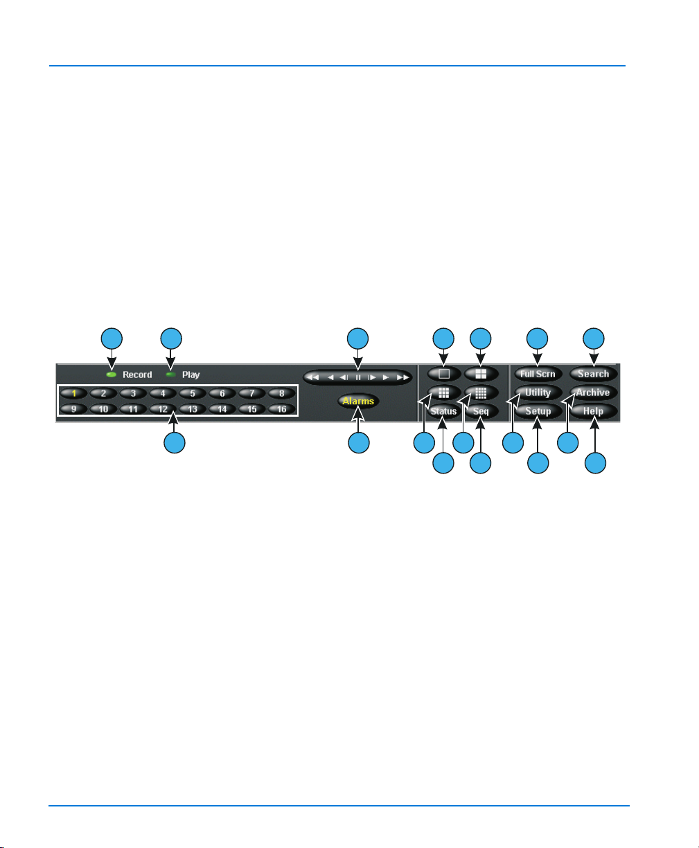
Installation and Operating Instructions
3. Archive — If a Digital Audio Tape (DAT) drive is installed, this progress bar
indicates how much tape recording space has been used and how much is
available. The bar only appears when archiving in the background (see Archive
Schedule Option on page 127).
4. Image Database — This progress bar indicates how much recording space in the
image database has been used and how much is available.
5. Mute — Click to mute audio.
6. Volume Slider — Slide the volume slider to adjust the output level of the
playback audio.
On-screen Controls and Indicators
Operate the unit using the mouse pointer and the following on-screen controls.
7 8
9
10
11
12
13 18 19
14
15 20 21
16
17
22
23
Figure 7 — On-screen Controls
7. Record — This indicator is lit when the unit is recording images. On the front
panel, this indicator is labeled REC.
8. Play — This indicator is lit when the unit is playing back images. Play changes to
Pause when playback is paused.
9. 1–16 (Cameras) — Click to display a specific camera in the 1x1 format. The text
on the camera button changes from white to yellow to show that the camera has
been selected. In multi-camera display (live or playback), drag and drop a camera
button to any image pane.
10. Playback Controls — Controls how images are displayed during image
playback. You can choose between the Jog/Shuttle or VCR type of control during
setup by clicking the Display button on the Setup Options screen.
Jog/Shuttle (Play/Pause button) — You can control play/pause as well as
playback direction and speed by clicking and dragging the on-screen control (see
Playback Operation on page 153).
36 Main Screen

Intellex DV16000 Digital Video Management System
VCR Play/Pause Control — You can control play/pause as well as playback
direction and speed by clicking each of the icons on the on-screen control. The
center icon selects pause mode, controls to the right are forward play then fast
play, the controls to the left are reverse play and fast reverse play. If in pause
mode, play or reverse play will display image by image instead of regular
playback (see Playback Operation on page 153 for more information).
11. Alarms — Click to display the alarm review screen (see Alarm Review Screen on
page 193). The text on the button changes from white to yellow if there are alarms
to review. Unless all alarms are reviewed, the text remains yellow.
12. 1x1 — Click to select the single window format (1x1). Only one camera can be
displayed at a time unless you start camera sequencing (see Screen Format on
page 136 and Camera Sequencing on page 140).
13. 2x2 — Click to select the four-window (2x2) format. Up to four cameras can be
displayed at the same time (see Screen Format on page 136 for more information).
14. 3x3 — Click to select the nine-window (3x3) format. Up to nine cameras can be
displayed at the same time (see Screen Format on page 136 for more information).
15. 4x4 — Click to select the 16-window (4x4) format. Up to 16 cameras can be
displayed at the same time (see Screen Format on page 136 for more information).
16. Status — Click to display the unit’s status screen (see Reviewing Unit Status on
page 143).
17. Seq (Sequence) — Click to display cameras sequentially (see Camera Sequencing
on page 140).
18. Full Scrn — Click to hide the controls and indicators and to display the current
images full-screen in the selected screen format. To exit the full screen format,
right click anywhere on screen. The menu displays, select Switch to Menu, then
click to return to displaying on-screen controls and indicators.
19. Search — Click to search the image database for specific video images.
20. Utility — Click to access the Utility Options screen (see Utility Options on
page 145).
21. Archive — Click to access the Archive Options screen (see Archive Schedule Option
on page 127).
22. Setup — Click to access the system configuration options (see Setup Options on
page 39).
23. Help — Click to display online help information.
Main Screen 37

Installation and Operating Instructions
38 Main Screen

SETUP OPTIONS
The Intellex Setup Options allow you to access each of the system settings. You can
configure the Cameras, Security, Schedule, etc. using this screen. The following is a list
of the topics discussed in this chapter.
• Setup Options Screen
• Cameras Option
• Schedule Option
• Camera Selectable Rate Option
• Text Option
•Audio Option
• Security Option
• Record Mode Option
• Alarms Option
• Display Option
• Date/Time Option
• Port Address Option
• Storage Option
• Archive Schedule Option
Setup Options 39

Installation and Operating Instructions
SETUP OPTIONS SCREEN
Access each system setting through the Setup Options screen. Click the Setup button
on the main screen and the Setup Options screen appears.
NOTE: You must possess the appropriate privilege to access a setup option (see
Security Setup on page 31).
Select one of the following options to access the corresponding screen:
Cameras
(page 42)
Schedule
(page 113)
Rate
(page 88)
Text
(page 94)
Audio
(page 104)
Security
(page 106)
Record Mode
(page 113)
Alarms
(page 116)
Display
(page 120)
Date/Time
(page 123)
Click to access the Cameras option. Use to configure the
names and termination settings for each camera, audio
association, camera control, and gain settings.
Click to access the Schedule option. Use to define how
the unit records images in this installation, including
daytime and nighttime operation, and weekday,
weekend and holiday operation.
Click to access the Rate option. Use to configure a
specific recording rate for each camera, or to have the
Intellex unit automatically distribute the recording rate
evenly across all active cameras.
Click to access the Te xt option. Use to add, edit or delete
text streams.
Click to access the Audio option. Use to define audio text
streams and associate with one or more camera.
Click to access the Security option. Use to assign the
name, personal identification number (PIN) and
privileges for each user.
Click to access the Record Mode option. Use to define
how the unit records regular (nonalarm) images.
Click to access the Alarms option. Use to define how the
unit responds to various alarm conditions.
Click to access the Display option. Use to define the
display settings and to assign cameras to specific
locations in each live display format.
Click to access the Date/Time option. Use to define the
system date and time, which are encoded on each
image.
40 Setup Options

Intellex DV16000 Digital Video Management System
Port Address
(page 124)
Click to access the Port Address option. Use to specify a
fixed port address for the Intellex unit to use for
connecting to a network.
Storage
Click to access the Storage option.
(page 125)
Archive Schedule
(page 127)
Click to access the Archive Schedule option. Use to
create custom archive schedules.
Click Close to cancel and to return to the main screen. Click Help to display online
help for this screen.
Setup Options 41

Installation and Operating Instructions
CAMERAS OPTION
The Cameras option allows you to define a name, termination settings, set the gain
level, and select a camera handler for each camera.
NOTE: You must possess the Setup Cameras privilege to access this screen (see
Security Option on page 106).
1. From the main screen, click the Setup button. The Setup Options screen appears.
2. Click the Cameras button. The Names tab (the first Camera Setup screen)
appears.
Cameras Names Use to define the name of each camera. These
Termination Since terminators are not required on Intellex
Gain Mode Use the Gain Mode tab to set the gain level for
Camera Control Use to select a camera handler for each
Covert Mode Use to select the camera(s) to operate in
names are displayed when viewing live
images and are stored in the image database
with recorded images.
units, define each camera’s setting, either 75
Ohms or Hi-Z. The default is 75 Ohms.
each camera.
camera that is to be controlled.
covert mode.
Names Tab
Use the mouse pointer to highlight one of the current camera names. Then use the
virtual keyboard or the physical keyboard (if attached) to enter the new name, up to
10 characters. The default names are Camera1 through Camera16.
Click OK to accept the changes made. Click Cancel to cancel the changes. Click Help
to display online help for this screen.
Termination Tab
When set to 75 Ohms, the unit terminates the camera. This is the same as installing a
terminator on the associated Camera Out connector.
When set to Hi-Z, the camera signal is passed through to the associated Camera Out
connector. This is the same as removing a terminator and attaching a cable to the
associated Camera Out connector.
42 Setup Options

Click OK to accept the changes made. Click Cancel to cancel the changes. Click Help
to display online help for this screen.
Gain Mode Tab
Use the Gain Mode tab to change the gain level in order to correct video that is too
bright or too dark. Using twisted pair wire to connect cameras to the unit may result
in video that is too dark. To correct for brightness or darkness, reduce or increase the
Gain Mode setting.
In the pull-down box to the right of a camera name, select one of the following Gain
Mode settings:
Reduce Gain Use to reduce brightness or color bursts.
Normal Use for video that is acceptable. This is the default
Boost Gain Low Use Low for twisted pair wire up to 500 ft. (152 m)
Boost Gain Medium Use Medium for twisted pair up to 1000 ft. (305 m)
Boost Gain High Use High for twisted pair up to 1500 ft. (457 m)
After you select a Gain Mode setting, all associated values, such as luma and chroma
gain, are adjusted automatically as needed for each setting. Gain Mode settings are
communicated to any connected Network Client application.
Intellex DV16000 Digital Video Management System
setting.
Camera Control Tab
Connection between the Intellex unit and the dome requires an EIM and Touch
Tracker. Supported domes include the following:
• SensorNet-connected SpeedDome (Ultra IV, Ultra V, or Ultra VI when available),
and
• Optima (and compatible domes such as Ultra III) with firmware version 3.05 or
later.
Remote control functions include Dome Select, Pan, Tilt, Zoom, Focus, Iris control and
Call Preset.
NOTE: Before you change any Camera Control configuration settings in the Intellex
unit, you must first connect the Touch Tracker to the Intellex unit in accordance
with the Touch Tracker installation instructions. Refer to the VM16 Plus
Enhanced Touch Tracker Installation Guide, part number 8000-2672-01.
You must configure each of the cameras that will be controlled through the Intellex
Setup function.
Setup Options 43

Installation and Operating Instructions
1. From the main screen, click the Setup button. The Setup Options screen appears.
2. Click the Cameras button and click the Camera Control tab.
3. For each of the cameras that will be controlled, select one of the camera handlers
from the pull-down menu:
None Select if this camera cannot be controlled or you do
AD168, MP48 Select if you have an AD168 or MP48 Matrix
AD1024 Matrix Select if you have an AD1024 switcher or if your
RS422 Dome Select if you have an RS422-connected dome.
VM16/ADTT16 Select if you have a VM16 or ADTT16E Touch
VM16E/ADTT16E V2.x Select if you have a VM16 or ADTT16E with version
NOTE: The Version 2.x firmware permits simultaneous local (at the Touch Tracker)
and remote (via Network Client) control of different cameras through the same
Touch Tracker. The Touch Tracker must have version 2.x firmware for this
mode to work.
4. After you select a camera handler, the Setup button will be active for that camera.
Click Setup to go to the Camera Control Setup screen , where you specify the
camera address and COM port. You MUST perform Setup on each camera with a
camera handler selected for proper operation of the Intellex unit.
• The default camera address is the Intellex camera number. Normally this is
correct. If the ADTT16E V2.x camera handler is used, the SensorNet address of
the camera must be used.
• The MUX port is the COM2 port that is normally used when the Touch Tracker
is used to select cameras on Intellex. This MUX port must be used if Touch
Tracker control is desired. Any other COM port on the Intellex can be used
only for camera control.
NOTE: The monitor number selection will switch the camera to the selected monitor
output on the switch. If local switching of the video is not desired, select an
unused monitor output on the Intellex.
NOTE: The RS-232 port on the matrix switcher MUST be set to Terminal Mode when
connecting an Intellex to an AD matrix switcher for camera control. The baud
rate on the matrix switcher should be set to 4800.
not wish to permit remote control of this camera.
This is the default setting.
Switcher, or if your switcher uses make/break or
start/stop polling.
switcher uses continuous polling.
Tracker or Enhanced Touch Tracker.
2.x firmware.
44 Setup Options

Click OK to accept the changes made. Click Cancel to cancel the changes. Click Help
to display online help for this screen.
Covert Mode Tab
The Covert Camera feature allows authorized users to capture video from a hidden
camera without the knowledge of another Intellex user.
NOTE: Only authorized users can configure and view covert cameras. Unauthorized
users can neither view covert cameras nor the Covert Mode tab. Security
needs to be enable before the Covert Cameras tab is visible and enabled.
Configuring a Covert Camera
NOTE: You must possess the Setup Covert Cameras privilege to access the Covert
Mode tab (see Security Option on page 106).
CAUTION: Disabling Covert Mode makes all recorded video visible to all users.
1. From the main screen, click the Setup button. The Setup Options screen appears.
2. Click the Cameras button. The Names tab (the first Camera Setup screen)
appears.
3. Click the Covert Mode tab.
4. Find the desired camera(s) and select Covert from the pull-down menu.
5. Click OK.
NOTE: A covert camera appears as a disconnected camera to unauthorized users.
Therefore, we recommend you set up the last cameras in the list as covert.
Intellex DV16000 Digital Video Management System
Live Mode
Live Mode behavior is different for users with authorized covert camera privileges.
Authorized Users
When an authorized user views live video from a covert camera, the pane displays the
video, the camera name, and an asterisk (*) indicating that this is a covert camera.
If an authorized user right-clicks a covert camera’s live video pane to display the
Image Area Popup menu, the covert camera name is preceded by an asterisk (*)
indicating that this is a covert camera.
Setup Options 45

Installation and Operating Instructions
Unauthorized Users
When an unauthorized user attempts to view live video from a covert camera, the
pane displaying that camera appears as if the camera is not connected. Rather than
displaying the actual name of the covert camera, the default camera name is
displayed. This conceals the fact that there may be a hidden camera.
When an unauthorized user right-clicks a covert camera’s live video pane to display
the Image Area Popup menu, the covert camera behaves like a disconnected camera.
The Single Pane and Generate Alarm items are grayed out, as is the camera’s default
name in the list.
Playback Mode
Playback Mode behavior is also different for users with authorized covert camera
privileges.
Authorized User
When an authorized user plays video from a covert camera in single pane or
multipane mode, the screen displays the video, camera name, and an asterisk (*)
indicating that this is a covert camera.
If an authorized user right-clicks a covert camera’s playback pane to display the
menu, the covert camera name is preceded by an asterisk (*) indicating that this is a
covert camera.
Unauthorized User
An unauthorized user cannot play video from a covert camera in single pane or
multipane mode. In single pane mode, the screen displays the default camera name
and the message “No Video.” In multipane mode, the screen displays only the default
camera name.
If an unauthorized user right-clicks a covert camera’s playback pane to display the
menu, the covert camera behaves like a disconnected camera. The “Single Pane,”
“Remove,” and “Tools” items are grayed out, as well as the camera’s default name in
the list.
46 Setup Options

Exporting with a Covert Camera
When an unauthorized user opens the Export screen, all covert cameras behave as if
they are not connected. An unauthorized user can select the checkboxes for all
cameras except the covert cameras or disconnected cameras. If an unauthorized user
selects the name of a covert camera, the name is highlighted, but the video remains
unchanged from what was previously displayed. Only video from normal cameras
can be exported; none of the covert cameras can export video.
If audio or text are associated only with covert cameras, then the Audio and Text
Streams area remain blank, and the audio or text streams are not exported. However,
if audio or text streams are associated with any normal camera, audio and text appear
in the Audio and Text Streams area.
NOTE: When you log out, your clip list is saved and will be restored the next time you
log in. Other users cannot view covert camera video clips that were left in the
clip list by an authorized user.
Status Screen
When an unauthorized user views the Status screen, any camera that is covert
displays a red “X” over the camera and record icons to indicate that there is no camera
connected, the mode displays Active, the Quality and Sensitivity fields display
“Normal”, and the Pre-Alarm field displays “- - - - “, and the Filter field is left blank.
The default camera name is displayed instead of the actual name of the covert camera.
Intellex DV16000 Digital Video Management System
When an authorized user views the Status screen, the true status of all cameras is
displayed. In addition, all covert cameras are indicated by an asterisk (*) preceding
the camera name.
Setup Options 47

Installation and Operating Instructions
SCHEDULE OPTION
The Schedule option allows you to configure how the unit records images under a
variety of circumstances.
NOTE: You must possess the Setup Schedule privilege to access it (see Adding a
New User on page 108).
1. From the main screen, click the Setup button. The Setup Options screen appears.
2. Click the Schedule button. The Mode tab (the first Schedule Setup screen)
appears.
The Mode tab allows you to indicate whether the unit will operate on a regular,
custom or single camera schedule. The default is Use Regular Schedule.
Use Regular Schedule Select this option to use the same schedule for all
Use Custom Schedule
(page 54)
Use Single Camera
Schedule
(page 86)
cameras.
Select this option to create custom schedules for each
camera.
Select this option to record images from a single
camera.
Use Regular Schedule
The Use Regular Schedule option allows you to use the same schedule for all
cameras. The unit uses the same schedule for weekdays, weekends and holidays.
Daytime operation begins at the set start time and switches to nighttime operation at
its start time.
Select the Use Regular Schedule option. The unit displays the Quality, Time,
Cameras 1–8, Cameras 9–16, and Data Lifetime tabs, and removes all other tabs.
48 Setup Options

Quality Tab
Intellex DV16000 Digital Video Management System
Use the Quality tab to set the quality for normal operation.
Quality Select the record quality to use for regular operation. The default
setting is Normal.
Super Record images at the highest image quality.
Since the unit uses the lowest level of
compression, this setting requires the highest
amount of storage space.
Normal Record images at normal image quality. This
setting provides a balance between
compression and storage space requirements.
Extended Record Record images at the highest level of
compression. This setting requires the lowest
amount of storage space.
Sensitivity This setting lets you control how Intellex responds to small, subtle
changes between images. Select the sensitivity for regular
operation. The default is Normal.
High At this setting, Intellex records the smaller
changes between images, improving the
perceived picture quality. As a result, this
setting requires more storage space.
Normal At this setting, Intellex ignores the smaller,
more subtle changes between images.
Resolution This setting lets you choose either 640x240 or 320x240. The default
is 640x240.
640x240 This setting offers higher resolution, but less
recording time.
320x240 This setting provides less resolution, but
extends the recording time.
Select another Regular Schedule Setup Option for configuration. Otherwise, click OK
to accept the new settings, and return to the Setup Options screen. Click Cancel to
cancel the changes. Click Help to display online help for this screen.
Setup Options 49
Installation and Operating Instructions
Time Tab
Use the Time tab to set the start times for daytime and nighttime operation.
Start day at Use this option to set the start time for daytime processing in
24-hour format. The default is 06:00 (6:00 a.m.).
Start night at Use this option to set the start time for nighttime processing in
24-hour format. The default is 18:00 (6:00 p.m.).
1. Click the hours display. Click the up arrow or down arrow to display the desired
hour (24-hour format).
2. Click the minutes display. Click the up arrow or down arrow to display the
desired minutes (30-minute increments).
Select another Regular Schedule Setup Option for configuration. Otherwise, click OK
to accept the new start times, and return to the Setup Options screen. Click Cancel to
cancel the changes. Click Help to display online help for this screen.
Cameras (1-8 and 9-16) Tabs
Use the Cameras 1–8 and Cameras 9–16 tabs to configure a live filter for each
camera, one for daytime and one for nighttime operation. If you configure a filter and
activity is detected (for example, in the target area of the motion detection filter), the
unit records images from the camera at the record rate specified in the Alarm Setup
screens.
Cameras All camera names are listed down the left side of the
screen in camera order.
Day Filter Use this option to select a live filter for this camera
during daytime operation. The default is None.
NOTE: Before you can configure a live filter, you must
record at least one image from the camera.
Until an image is recorded, the filter options are
disabled.
Night Filter Use this option to select a filter for this camera during
nighttime operation. The default is None.
Setup Select a filter; then click Setup to configure it (see Live
Filter Configuration on page 70).
1. Click the down arrow. A list of filters appears.
2. Click the desired filter. Select None to disable any previously configured filters.
3. Click Setup to configure the filter.
50 Setup Options

Select another Regular Schedule Setup Option for configuration. Otherwise, click OK
to accept the new day/night filter settings, and return to the Setup Options screen.
Click Cancel to cancel the changes and return to the Setup Options screen. Click Help
to display online help for this screen.
Regular Schedule Popup Menu
The regular schedule popup menu provides access to several regular schedule
configuration options.
NOTE: The popup menu will not appear unless a filter name appears in one of the
filter fields.
1. Move the mouse pointer over either the Day Filter or the Night Filter next to a
camera name.
2. Click the down arrow. A list of filters appears.
3. Click the desired filter. Select None to disable any previously configured filters.
4. Click the right mouse button. The regular schedule popup menu appears (one or
more options may not be available).
NOTE: Before you can configure a filter, you must record at least one image from the
camera. Until an image is recorded, the filter options are disabled.
Setup Use this option to configure the selected filter for this
Copy Use this option to copy a filter configuration into the
Paste Use this option to copy a filter configuration from a
Replace Use this option to copy a filter configuration over an
Delete Use this option to delete a filter configuration.
Intellex DV16000 Digital Video Management System
camera. This option operates the same as pressing the
Setup button.
unit’s memory. Then, use Paste or Replace to assign the
filter configuration to the other filter field (Day Filter or
Night Filter).
NOTE: This option is disabled until you copy a
configured filter into memory
camera’s Day Filter to its Night Filter or vice versa.
NOTE: You cannot paste a filter configuration from one
camera to another camera.
existing filter configuration. Use this option when
overwriting an existing filter configuration.
Setup Options 51

Installation and Operating Instructions
Copying and Pasting a Filter
1. Select the filter to copy.
2. Click the right mouse button to display the regular schedule popup menu.
3. Select Copy. The unit copies the filter’s information into memory.
4. Select the filter field to add the filter configuration you copied.
5. Click the right mouse button to display the regular schedule popup menu.
6. Select Paste. The unit pastes the filter’s configuration information into the other
filter field.
Replacing a Filter
1. Select the filter to replace.
2. Click the right mouse button to display the regular schedule popup menu.
3. Select Replace. The filter’s configuration replaces the existing filter.
Deleting a Filter
1. Select the filter to delete.
2. Click the right mouse button to display the regular schedule popup menu.
3. Select Delete. The unit deletes the filter configuration.
Data Lifetime Tab
Use the Data Lifetime tab to enable or disable deletion of selected video data and to
select the cameras that will use Data Lifetime deletion.
Programming the Data Lifetime for individual cameras increases the time required to
scan the database and to delete expired images. Use the All Cameras selection
whenever possible. This is especially important with multiple disks and/or external
disk storage systems.
It may not be possible to restore a tape while Data Lifetime is cleaning the database.
Avoid Restore operations during Data Lifetime processing.
Disabled Select this option to disable the deletion of selected video
data. The default setting is Disabled.
Select Cameras Select this option to specify which camera(s) will delete data
according to your Data Lifetime settings. Click the Setup
button.
Setup The list of available cameras is displayed. Select a
camera and then specify its Data Lifetime data
duration in number of days ranging from 1 to 199.
The default setting is 14 days.
52 Setup Options

Intellex DV16000 Digital Video Management System
All Cameras Select this option to specify the Data Lifetime data duration
for all cameras.
Start Time Set the time for data deletion to begin. To change the time
setting, select the hour or minutes and click on the up or down
arrow to specify the desired start time.
Click OK to accept the new schedule mode, and return to the Setup Options screen.
Click Cancel to cancel the changes. Click Help to display online help for this screen.
Setup Options 53

Installation and Operating Instructions
Use Custom Schedule
The Use Custom Schedule option creates a custom schedule for each camera. For
weekdays, weekends and holidays, select operating hours, recording modes and
filters for each camera.
Select the Use Custom Schedule option. The unit displays the Time, Weekday,
Weekend, Holiday, Set Holidays, and Data Lifetime tabs, depending on selected
options, and removes all other tabs.
Use Custom
Schedule
Click OK to accept the new schedule mode, and return to the Setup Options screen.
Click Cancel to cancel the changes. Click Help to display online help for this screen.
Select this option to create custom schedules for each camera.
Include Weekend Select this option to create different
schedules for weekend operation, including
operating hours, recording modes and
filters for each camera. The Time and
Weekend tabs appear. When Use Custom
Schedule is selected, this option is selected
by default.
Include Holiday Select this option to create different
schedules for holiday operation, including
operating hours, recording modes and
filters for each camera. The Time, Holiday
and Set Holidays tabs appear. When Use
Custom Schedule is selected, this option is
selected by default.
54 Setup Options

Time Tab
Intellex DV16000 Digital Video Management System
Use the Time tab to set the start and end times for weekends and holidays. This tab
only appears if Include Weekend and/or Include Holiday is selected on the Mode
tab (see Use Custom Schedule on page 54)
.
Weekend Days Choose to use the weekend schedule on Saturdays, Sundays
or both. The default is Saturday and Sunday.
To use the weekday schedule on Saturdays and Sundays,
deselect the Include Weekend option on the Mode tab.
Saturday and
Sunday
Select this option to use the weekend
schedule on Saturdays and Sundays. The
unit changes the Weekend Start/End
Times options to Include part of Friday
and Include part of Monday.
Saturday Only Select this option to use the weekend
schedule only on Saturdays. The unit will
use the weekday schedule on Sundays.
The unit changes the Weekend Start/End
Times options to Include part of Friday
and Include part of Sunday.
Sunday Only Select this option to use the weekend
schedule only on Sundays. The unit will
use the weekday schedule on Saturdays.
The unit changes the Weekend Start/End
Times options to Include part of Saturday
and Include part of Monday.
Setup Options 55

Installation and Operating Instructions
Weekend Start/
End Times
Holiday Start/
End Times
Start weekend processing at a specific time on the day before
the weekend, for example, at 6:00 p.m. on Friday night.
Likewise, stop weekend processing at a specific time on the
day after the weekend, for example, at 6:00 a.m. on Monday
morning.
Include part of
Friday
Select this option to start weekend
processing at a specific time on the day
before the weekend.
Set the time to start weekend processing on
the day before the weekend. The default is
18:00 (6:00 p.m.).
Include part of
Sunday
Select this option to stop weekend
processing at a specific time on the day
after the weekend.
Set the time to stop weekend processing on
the day after the weekend. The default is
06:00 (6:00 a.m.).
Start holiday processing at a specific time on the day before
the holiday, for example, at 6:00 p.m. on the night before.
Likewise, stop holiday processing at a specific time on the day
after the holiday, for example, at 6:00 a.m. on the morning
after.
Include part of
day before
Select this option to start holiday
processing at a specific time on the day
before the holiday.
Set the time to start holiday processing on
the day before the holiday. The default is
18:00 (6:00 p.m.).
Include part of
day after
Select this option to stop holiday
processing at a specific time on the day
after the holiday.
Set the time to stop holiday processing on
the day after the holiday. The default is
06:00 (6:00 a.m.).
By default, weekends and holidays include part of the day before and part of the day
after. If the day before is not included, processing starts at midnight. Likewise, if the
day after is not included, processing stops at midnight.
To use the weekday schedule on weekends, deselect the Include Weekend option on
the Mode tab.
56 Setup Options

To use the weekday or weekend schedule on holidays, deselect the Include Holiday
option on the Mode tab.
1. Click the hours display. Click the up arrow or down arrow to display the desired
hour (24-hour format).
2. Click the minutes display. Click the up arrow or down arrow to display the
desired minutes (30-minute increments).
Select another Custom Schedule option for configuration. Otherwise, click OK to
accept the new weekend and holiday settings, and return to the Setup Options screen.
Click Cancel to cancel the changes. Click Help to display online help for this screen.
Weekday/Weekend/Holiday Tabs
Use the Weekday, Weekend and Holiday tabs to configure the operating schedule for
each camera. All three tabs operate the same way. The Weekend tab only appears if
Include Weekend is selected on the Mode tab. The Holiday tab only appears if
Include Holiday is selected on the Mode tab.
Schedule Area Use the main schedule area to define and display the
Active Select this option to define an active segment. During
Alarmed Select this option to define an alarmed segment.
Disabled Select this option to define a disabled segment. During
Intellex DV16000 Digital Video Management System
active, alarmed and disabled segments for each
camera. Hours are listed across the top of the schedule
area in 30-minute segments. Camera names are listed
down the left side of the schedule area in numerical
order (1–16).
an active segment, the unit records images from the
camera at the configured record rate and quality. A
live filter can also be configured for the segment.
During an alarmed segment, the unit only records
images from the camera when the live filter or alarm
input is activated. It records at the configured record
rate and quality. It can also store a selected amount of
pre-alarm images.
a disabled segment, the unit does not record or display
any images from the camera. It also ignores any
alarms.
NOTE: Disabled segments cannot be configured.
Setup Options 57

Installation and Operating Instructions
Setup After they are defined, you can configure active and
Undo Click this button to undo the last change. Each time
Resolution This setting allows you to choose either 640x240 or
1. Define the segment as shown in Working with Schedule Segments on page 60.
2. Use one of the following options:
• Double-click the segment to configure.
• Select the segment to configure; then click Setup.
• Select the segment to configure; then access the custom schedule popup menu
(see Custom Schedule Popup Menu on page 62); then select Setup.
alarmed segments (see Configuring an Active Segment
on page 66 and Configuring an Alarmed Segment on
page 68).
you access these screens, the unit keeps track of the
changes. It remembers up to the last 10 changes on
each Custom Schedule Setup screen (Weekday,
Weekend and Holiday). When the button becomes
disabled, you cannot undo any more changes.
320x240. 640x240 offers higher resolution, but less
recording time. 320x240 provides less resolution, but
extends the recording time. The default is 640x240.
Select another Custom Schedule Setup Option for configuration. Otherwise, click OK
to accept the new displayed schedule, and return to the Setup Options screen. Click
Cancel to cancel the changes. Click Help to display online help for this screen.
58 Setup Options

Set Holidays Tab
Use the Set Holidays tab to identify the days that will operate using the holiday
schedule. This tab only appears if Include Holiday is selected on the Mode tab.
(Date) This field displays the date to add to the holiday list.
Holidays This window lists all dates that have been flagged as
Add to list Click to add the displayed date to the list of holidays.
Remove from list Click to remove the highlighted holiday from the list
To add a holiday to the list:
1. Click the down arrow in the date box to display the calendar.
2. Click the left arrow to select the previous month or right arrow to select the next
month.
3. Click the day of the month to select the day. The calendar closes and the selected
date is displayed.
4. Click the Add to list button. The unit displays the date in the holiday list.
Intellex DV16000 Digital Video Management System
holidays (in chronological order). The unit uses the
holiday schedule on each date in the list.
On that day, the unit will use the holiday schedule.
and display it in the date field. On that day, the unit
will use the appropriate weekday or weekend
schedule and will not use the holiday schedule.
To remove a holiday from the list:
1. Select the date in the holiday list. To view other dates, click the up arrow or down
arrow or drag the scroll button up or down.
2. Click the Remove from list button. The unit removes the date from the list of
holidays and displays it in the date field.
Select another Custom Schedule Setup Option for configuration. Otherwise, click OK
to accept the new displayed list of holidays. Click Cancel to cancel the changes. Click
Help to display online help for this screen.
Setup Options 59

Installation and Operating Instructions
Data Lifetime Tab
Use the Data Lifetime tab to enable or disable deletion of selected video data and to
select the cameras that will use Data Lifetime deletion.
Programming the Data Lifetime for individual cameras increases the time required to
scan the database and to delete expired images. Use the All Cameras selection
whenever possible. This is especially important with multiple disks and/or external
disk storage systems.
Working with Schedule Segments
Schedule segments define how the unit processes images from any camera at any
time. The unit can record at all times or only during alarms or filter events. Recording
can even be disabled during certain hours.
This explains how the mouse pointer changes according to the function you are
performing and where the mouse pointer is on the screen.
The cursor pointer changes to this when copying a camera
segment.
The cursor pointer changes to this while you are defining a new
segment.
The cursor pointer changes to this when moved over the start or
end time.
The cursor pointer changes to this if it is dragged to an area of the
screen without a camera name.
Defining a New Segment
1. Select the appropriate tab: Weekday, Weekend or Holiday.
2. Select the segment type: Active, Alarmed or Disabled.
3. Move the mouse pointer to the schedule line for the camera. An indicator appears
next to the camera name to help keep track of the pointer’s position.
4. Move the mouse pointer to the segment start time. An indicator appears next to
the matching 30-minute mark to help keep track of the pointer’s position.
5. Click and hold the mouse button.
6. Drag the mouse pointer to the right or left. A box displays the segment’s new start
and end times (24-hour format).
7. When the desired times appear, release the mouse button.
60 Setup Options

8. After defining an active or alarmed segment, configure its live filter and other
settings.
Changing a Segment
NOTE: To change a start time of 00:00 or an end time of 24:00, define a new segment
1. Select the appropriate screen: Weekday, Weekend or Holiday.
2. Move the mouse pointer over the start or end time for the segment to change.
3. Click and hold the mouse button.
4. Drag the mouse pointer to the right or left. A box displays the segment’s new start
and end times (24-hour format).
5. When the desired times appear, release the mouse button.
6. When changing the times of adjacent segments, the unit chooses the segment that
you are enlarging. Then it displays the times for that segment.
7. For example, when enlarging an alarmed segment (00:00 to 07:00) that is next to an
active segment (07:00 to 18:00), click on the boundary between the segments
(07:00) and drag right. The unit displays the alarmed segment’s new times, as long
as the boundary stays to the right of 07:00. If the boundary is dragged left past
07:00, the unit chooses the active segment and displays the new times for the
active segment.
8. After changing an active or alarmed segment, configure its live filter and other
settings (see Configuring an Active Segment on page 66 and Configuring an Alarmed
Segment on page 68).
Intellex DV16000 Digital Video Management System
which starts at 00:00 or ends at 24:00, respectively (see Defining a New
Segment on page 60).
Deleting a Segment
1. Select the appropriate screen: Weekday, Weekend or Holiday.
2. Use one of the following methods to delete a segment:
• Create a new segment over the segment to delete.
• Change the start time of the segment to match its end time.
• Change the start time of the next segment to the start time of the segment to
delete.
• Change the end time of the previous segment to the end time of the segment to
delete.
• Use the custom schedule popup menu to delete the segment (see Custom
Schedule Popup Menu on page 62).
Setup Options 61

Installation and Operating Instructions
Copying a Camera Schedule
1. Select the appropriate screen: Weekday, Weekend or Holiday.
2. Move the mouse pointer to the name of the camera to copy.
3. Click and hold the mouse button.
Drag the mouse pointer to the camera to change. The new segments appear on the
camera line.
Custom Schedule Popup Menu
The custom schedule popup menu provides access to a variety of custom schedule
configuration options.
1. Select a segment or move the mouse pointer over a camera name.
2. Click the right mouse button. The custom schedule popup menu appears (one or
more options may not be available).
Setup Use this option to configure an active or alarmed
Copy Use this option to copy one or more schedule segments
Paste Segment(s) Use this option to copy one or more segments from one
Paste Filter Use this option to copy a filter configuration from one
Paste Filter to All
Segments
Paste Segment(s) and
Filter(s)
Delete Segment(s) Use this option to delete one or more schedule
segment. This option operates the same as pressing the
Setup button on the Weekday, Weekend or Holiday
screens.
into the unit’s memory. Then, use a paste option to add
the segment and/or filter information to another
segment or camera.
camera to another.
segment of a camera to another segment of the same
camera on another screen.
Use this option to copy a filter configuration from one
segment of a camera to each segment of the same
camera on another screen.
Use this option to copy the segments and filters from
one camera line to that camera’s line on another screen.
segments from a camera’s line.
62 Setup Options

Intellex DV16000 Digital Video Management System
Delete Filter(s) Use this option to delete only filter configurations from
one or more segments on a camera’s line. This option
does not delete any segment time information.
Deleted Segment(s)
and Filter(s)
Use this option to delete one or more schedule
segments and their filter configurations (if any) from a
camera’s line.
To configure an active or alarmed segment:
1. Select the segment to configure.
2. Click the right mouse button to display the custom schedule popup menu.
3. Select Setup. The Active Segment screen appears for an active segment. The
Alarmed Segment screen appears for an alarmed segment.
To copy a segment:
NOTE: The unit can only save information from one copy operation at a time.
1. Select the segment to copy.
2. Click the right mouse button to display the custom schedule popup menu.
3. Select Copy. The unit copies the segment’s information into memory.
To copy all the segments for a camera:
1. Move the mouse pointer over the name of the camera to copy.
2. Click the right mouse button to display the custom schedule popup menu.
3. Select Copy. The unit copies the information for each segment on the line into
memory.
To paste a segment:
NOTE: This option is disabled until one or more segments have been copied into
memory. This option only adds segment time information to another camera.
1. Select the segment to copy.
2. Click the right mouse button to display the custom schedule popup menu.
3. Select Copy. The unit copies the segment’s information into memory.
4. To add this segment to a camera on another screen, select the tab (Weekday,
Weekend or Holiday).
5. Move the mouse pointer to the camera where you want to add the segment.
6. Click the right mouse button to display the custom schedule popup menu.
7. Select Paste Segment(s). The segment’s time information is added to the new
camera.
Setup Options 63

Installation and Operating Instructions
To copy all segments from one camera to another:
1. Move the mouse pointer over the name of the camera to copy.
2. Click the right mouse button to display the custom schedule popup menu.
3. Select Copy. The unit copies the information for each segment on the line into
memory.
4. To add this segment to a camera on another screen, select the screen (Weekday,
Weekend or Holiday).
5. Move the mouse pointer to the camera where you want to add the segment.
6. Click the right mouse button to display the custom schedule popup menu.
7. Select Paste Segment(s). The time information for all the segments is added to
the new camera.
To paste a filter:
NOTE: This option is disabled until a segment with a configured filter has been copied
into memory. This option only copies filter information to other segments for
the same camera.
1. Select the segment to copy.
2. Click the right mouse button to display the custom schedule popup menu.
3. Select Copy. The unit copies the segment’s information into memory.
4. Select the segment to add the filter you copied. (Select any active or alarmed
segment for the same camera on any screen.)
5. Click the right mouse button to display the custom schedule popup menu.
6. Select Paste Filter. The filter and its configuration information are added to the
new segment.
To paste a filter to all segments:
NOTE: This option is disabled until a segment with a configured filter has been copied
into memory.
1. Select the segment to copy.
2. Click the right mouse button to display the custom schedule popup menu.
3. Select Copy. The unit copies the segment’s information into memory.
4. Move the mouse pointer to the segment’s camera name. (Select the same camera
on any screen.)
5. Click the right mouse button to display the custom schedule popup menu.
6. Select Paste Filter to All Segments. The filter and its configuration information
are added to every active and alarmed segment on the line.
64 Setup Options

Intellex DV16000 Digital Video Management System
To paste segment(s) and filter(s):
NOTE: This option is disabled until a segment with a configured filter has been copied
into memory.
1. Move the mouse pointer over the name of the camera to copy.
2. Click the right mouse button to display the custom schedule popup menu.
3. Select Copy. The unit copies the information for each segment on the line into
memory.
4. Move the mouse pointer to the same camera name on another screen.
5. Click the right mouse button to display the custom schedule popup menu.
6. Select Paste Segment(s) and Filter(s). The segments and their filters are added
to the camera’s line.
To delete segments:
NOTE: This option is only available for segments without filters.
1. Select the segment to delete.
2. Click the right mouse button to display the custom schedule popup menu.
3. Select Delete Segment(s). If the deleted segment began at midnight (00:00), the
start time of the next later segment changes to midnight (00:00). Otherwise, the
next earlier segment replaces the deleted segment.
To delete all the segments for a camera:
1. Move the mouse pointer over the name of the camera with segments and filters to
delete.
2. Click the right mouse button to display the custom schedule popup menu.
3. Select Delete Segment(s). The unit deletes all segments and filters on the line.
To delete the filter for a camera:
1. Select the segment with a filter to delete.
2. Click the right mouse button to display the custom schedule popup menu.
3. Select Delete Filter(s). The unit deletes the filter.
To delete all the filters from the segments for a camera:
1. Move the mouse pointer over the name of the camera with filters to delete.
2. Click the right mouse button to display the custom schedule popup menu.
3. Select Delete Filter(s). The unit deletes the filter configurations for all segments
on the line.
Setup Options 65

Installation and Operating Instructions
To delete a segment for a camera:
1. Select the segment to delete.
2. Click the right mouse button to display the custom schedule popup menu.
3. Select Delete Segment(s) and Filter(s). If the deleted segment began at midnight
(00:00), the start time of the next later segment changes to midnight (00:00).
Otherwise, the next earlier segment replaces the deleted segment.
To delete all the segments for a camera:
1. Move the mouse pointer over the name of the camera with segments and filters to
delete.
2. Click the right mouse button to display the custom schedule popup menu.
3. Select Delete Segment(s) and Filter(s). The unit deletes all segments and filters
on the line.
Configuring an Active Segment
Use the Active Segment screen to configure both the record quality and the live filter
for the segment.
1. Define the segment (see Working with Schedule Segments on page 60).
2. Use one of the following options to display the Active Segment screen:
• Double-click the segment to configure.
• Select the segment to configure; then click Setup.
• Select the segment to configure; then access the custom schedule popup menu
(see Custom Schedule Popup Menu on page 62); then select Setup.
NOTE: Before you can configure a live filter, you must record at least one image from
the camera. Until an image is recorded, the filter options are disabled.
66 Setup Options

Intellex DV16000 Digital Video Management System
.
Active
segment:
Indicates the camera name and the segment’s start and end
times.
(camera name)
from hh:mm to
hh:mm
Quality Select the record quality to use for regular operation. The
default setting is Normal.
Super Record images at the highest image quality.
Since the unit uses the lowest level of
compression, this setting requires the highest
amount of storage space.
Normal Record images at normal image quality. This
setting provides a balance between
compression and storage space requirements.
Extended
Record
Record images at the highest level of
compression. This setting requires the lowest
amount of storage space.
Sensitivity This setting lets you control how Intellex responds to small,
subtle changes between images. Select the sensitivity for
regular operation. The default is Normal.
High At this setting, Intellex records the smaller
changes between images, improving the
perceived picture quality. As a result, this
setting requires more storage space.
Normal At this setting, Intellex ignores the smaller,
more subtle changes between images.
Live Filter Use this option to select the live filter to use during this
segment. When the live filter is activated, the unit switches to
alarm mode. The default is None.
Select None to disable any previously configured filters.
Resolution This setting lets you choose either 640x240 or 320x240. The
default is 640x240.
640x240 This setting offers higher resolution, but less
recording time.
320x240 This setting provides less resolution, but
extends the recording time.
Select another segment for configuration. Otherwise, click OK to accept the
Setup Options 67

Installation and Operating Instructions
configuration for this segment as shown, and return to the Weekday, Weekend or
Holiday screen. Click Cancel to cancel the changes. Click Help to display online help
for this screen.
Configuring an Alarmed Segment
Use the Alarmed Segment screen to configure the pre-alarm record quality and
duration for the segment as well as the live filter.
1. Define the segment (see Working with Schedule Segments on page 60).
2. Use one of the following options to display the Alarmed Segment screen:
• Double-click the segment to configure.
• Select the segment to configure; then click Setup.
• Select the segment to configure; then access the custom schedule popup menu
(see Custom Schedule Popup Menu on page 62); then select Setup.
Alarmed segment:
(camera name) from
Indicates the camera name and the segment’s start and
end times.
hh:mm to hh:mm
Pre-Alarm Quality Select the record quality for the pre-alarm images
recorded during this segment. The default is Normal.
NOTE: This quality setting only affects pre-alarm
images. To set the record quality of alarm
images, see Alarms Option on page 116.
Super Record images at the highest image
quality. Since the unit uses the
lowest level of compression, this
setting requires the highest amount
of storage space.
Normal Record images at normal image
quality. This setting provides a
balance between compression and
storage space requirements.
Extended Record Record images at the highest level
of compression. This setting
requires the lowest amount of
storage space.
68 Setup Options

Intellex DV16000 Digital Video Management System
Pre-Alarm Sensitivity This setting lets you control how Intellex responds to
small, subtle changes between images. Select the
sensitivity to use when storing pre-alarm images. The
default is Normal.
High At this setting, Intellex records the
smaller changes between images,
improving the perceived picture
quality. As a result, this setting
requires more storage space.
Normal At this setting, Intellex ignores the
smaller, more subtle changes
between images.
Pre-Alarm
Resolution
This setting lets you choose either 640x240 or 320x240.
The default is 640x240.
640x240 This setting offers higher
resolution, but less recording time.
320x240 This setting provides less
resolution, but extends the
recording time.
Live Filter Use this option to select the live filter to use during this
segment. When the live filter is activated, the unit
switches to alarm mode. The default is None.
NOTE: Before you can configure a live filter, you must
record at least one image from the camera. Until
an image is recorded, the filter options are
disabled.
Setup Select a filter for this segment; then
click Setup to configure it (see Live
Filter Configuration on page 70).
Pre-Alarm Duration The unit continuously saves pre-alarm images for each
camera, up to the pre-alarm duration. When an event
occurs, the unit records these images to the image
database. The default is 15 Seconds.
Select another segment for configuration. Otherwise, click OK to accept the
configuration for this segment as shown, and return to the Weekday, Weekend or
Holiday screen. Click Cancel to cancel the changes. Click Help to display online help
for this screen.
Setup Options 69

Installation and Operating Instructions
Live Filter Configuration
NOTE: Before following any procedures in this section, select the live filter and click
Setup (see Use Regular Schedule on page 48, Configuring an Active Segment on
page 66, and Configuring an Alarmed Segment on page 68).
After you select a live filter, use the appropriate filter configuration screen to
configure it.
• Motion Detection
• Perimeter Protection
•Light Change
• Motion Exception
To select a Live Filter:
1. Click the down arrow. A list of filters appears.
2. Click the desired filter. Select None to disable any previously configured filters.
3. Click Setup to configure the filter.
Motion Detection
After you select the Motion Detection filter and click the Setup button, the Motion
Detection screen appears. Use the Motion Detection screen to configure the target area
for the motion detection filter. Once configured, the filter is triggered whenever
movement occurs in the target area.
Motion Detection:
(camera name)
Image Area This area of the screen displays a camera image and provides
Active Zone Use the following options to configure the target area. This
70 Setup Options
Indicates the camera name.
a reference when configuring the filter.
area can be nearly any shape or size.
Activate Use this option to activate a specific target
area.
Deactivate Use this option to deactivate a previously
activated target area.
Restore Click to restore the target area to its
dimensions before any changes.
Clear Click to erase all of the targets in the active
zone.

Intellex DV16000 Digital Video Management System
All Click to activate all of the targets in the image
area.
Undo The unit stores each target area change in
memory. Click to remove the last change to
the target area.
Sensitivity The unit uses this setting to distinguish between valid and
invalid changes in the target area. At higher settings, small
changes trigger the filter. At lower settings, larger changes
are required to trigger the filter.
NOTE: When setting the filter sensitivity level, be sure to
consider the variations in lighting conditions, such as
exterior cameras recording from day to night or
interior cameras recording areas with lighting turned
on or off. To ensure that useful video is recorded or
filtered, nominal lighting in the area is required. You
should adjust the filter sensitivity for the lowest
lighting condition that applies (e.g., low sensitivity for
low lighting), and then test the filter to ensure its
proper activation. More lighting in the area will allow
higher sensitivity settings to be safely used.
1 … 100 Use this slide control to set the sensitivity for
the filter from minimum (1) to maximum
(100). The sensitivity number represents the
area of changing video relative to the active
zone area. Maximum sensitivity (1) requires
that a larger fraction of the active zone change
before the alarm is generated.
Default Click to reset the sensitivity to its default
middle position (50).
To define the target area(s):
NOTE: You can configure one or more motion detection target areas at a time.
1. Set the Sensitivity: 1 to 100.
2. Move the mouse pointer to the image area.
3. Draw the boundaries of the target area.
NOTE: The target area must be enclosed to activate the filter.
a. Move the mouse pointer to the first corner of the target area and click the
mouse button.
Setup Options 71

Installation and Operating Instructions
NOTE: To erase the last endpoint, double-click the right mouse button.
b. Move the mouse pointer to the next corner of the target area. The unit draws a
line as the pointer moves.
c. Click the mouse button to lock this boundary and start a new one.
d. Repeat these steps until you are ready to enclose the target area.
e. Use one of the following methods to enclose the target area:
• Set at least three endpoints. Then hold the mouse pointer over the last
endpoint and double-click the button. The boundary lines disappear and the
target area is defined by a semitransparent grid.
• Move the mouse pointer to the starting point and click the mouse button. The
boundary lines disappear and the target area is defined by a semitransparent
grid.
4. To draw an additional target area, repeat steps 1 through 3.
5. To deactivate some of the targets, select Deactivate. Then draw a deactivation
target area, using steps 1 through 3.
Click Apply to apply the configuration for this filter as shown and close the Motion
Detection screen. Click Cancel to cancel the changes. Click Help to display online
help for this screen.
Perimeter Protection
Use the Perimeter Protection screen to configure the target area for the perimeter
protection filter. Once configured, the filter is triggered whenever an object crosses
into or out of the target area.
After you select the Perimeter Protection filter and click the Setup button, the
Perimeter Protection screen appears.
Perimeter
Indicates the camera name.
Protection:
(camera name)
Image Area This area of the screen displays a camera image and
provides a reference when configuring the filter.
Active Perimeter Use the following options to configure the target area.
This area can be nearly any shape or size.
Restore Click to restore the target area to its
dimensions before any changes.
Clear Click to erase all of the targets in the
active zone.
72 Setup Options

Intellex DV16000 Digital Video Management System
Sensitivity The unit uses this setting to distinguish between valid
and invalid changes in the target area. At higher settings,
small changes trigger the filter. At lower settings, larger
changes are required to trigger the filter.
NOTE: When setting the filter sensitivity level, be sure to
consider the variations in lighting conditions, such
as exterior cameras recording from day to night
or interior cameras recording areas with lighting
turned on or off. To ensure that useful video is
recorded or filtered, nominal lighting in the area is
required. You should adjust the filter sensitivity for
the lowest lighting condition that applies (e.g., low
sensitivity for low lighting), and then test the filter
to ensure its proper activation. More lighting in
the area will allow higher sensitivity settings to be
safely used.
1 … 100 Use this slide control to set the
sensitivity for the filter from
minimum (1) to maximum (100).
The sensitivity number represents
the area of changing video relative
to the active zone area. Maximum
sensitivity (1) requires that a larger
fraction of the active zone change
before the alarm is generated.
Default Click to reset the sensitivity to its
default middle position (50).
1. Set the Sensitivity: 1 to 100.
2. Move the mouse pointer to the image area.
3. Draw the boundaries of the target area.
NOTE: The target area must be enclosed to activate the filter.
a. Move the mouse pointer to the first corner of the target area and click the
mouse button.
NOTE: To erase the last endpoint, double-click the right mouse button.
b. Move the mouse pointer to the next corner of the target area. The unit draws a
line as the pointer moves.
c. Click the mouse button to lock this boundary and start a new one.
d. Repeat these steps until you are ready to enclose the target area.
e. Use one of the following methods to enclose the target area:
Setup Options 73

Installation and Operating Instructions
• Set at least three endpoints. Then hold the mouse pointer over the last
endpoint and double-click the button. The boundary lines disappear and the
target area is defined by a semitransparent grid.
• Move the mouse pointer to the starting point and click the mouse button. The
boundary lines disappear and the target area is defined by a semitransparent
grid.
Click Apply to apply the configuration for this filter as shown and close the Perimeter
Protection screen. Click Cancel to cancel the changes and return to the previous
screen. Click Help to display online help for this screen.
Light Change
Use the Light Change screen to configure the target area for the light change filter.
Once configured, the filter is triggered whenever the light level changes. The light
level can change when someone turns lights on or off, uses a flashlight or blocks the
camera lens.
After you select the Light Change filter and click the Setup button, the Light Change
screen appears.
Light Change:
Indicates the camera name.
(camera name)
Image Area This area of the screen displays a camera image and
provides a reference when configuring the filter.
Active Zone Use the following options to configure the target area.
This area can be nearly any shape or size.
Restore Click to restore the target area to its
dimensions before any changes.
Clear Click to erase all of the targets in the
active zone.
74 Setup Options

Intellex DV16000 Digital Video Management System
Sensitivity The unit uses this setting to distinguish between valid
and invalid changes in the target area. At higher settings,
small changes trigger the filter. At lower settings, larger
changes are required to trigger the filter.
NOTE: When setting the filter sensitivity level, be sure to
consider the variations in lighting conditions, such
as exterior cameras recording from day to night
or interior cameras recording areas with lighting
turned on or off. To ensure that useful video is
recorded or filtered, nominal lighting in the area is
required. You should adjust the filter sensitivity for
the lowest lighting condition that applies (e.g., low
sensitivity for low lighting), and then test the filter
to ensure its proper activation. More lighting in
the area will allow higher sensitivity settings to be
safely used.
1 … 100 Use this slide control to set the
sensitivity for the filter from
minimum (1) to maximum (100).
The sensitivity number represents
the area of changing video relative
to the active zone area. Maximum
sensitivity (1) requires that a larger
fraction of the active zone change
before the alarm is generated.
Default Click to reset the sensitivity to its
default middle position (50).
NOTE: You can only configure one light change target area at a time.
1. Set the Sensitivity: 1 to 100.
2. Move the mouse pointer to the image area.
3. Draw the boundaries of the target area.
NOTE: The target area must be enclosed to activate the filter.
a. Move the mouse pointer to the first corner of the target area and click the
mouse button.
NOTE: To erase the last endpoint, double-click the right mouse button.
b. Move the mouse pointer to the next corner of the target area. The unit draws a
line as the pointer moves.
Setup Options 75

Installation and Operating Instructions
NOTE: The pointer changes to if it is dragged to an invalid location.
c. Click the mouse button to lock this boundary and start a new one.
d. Repeat these steps until you are ready to enclose the target area.
e. Use one of the following methods to enclose the target area:
• Set at least three endpoints. Then hold the mouse pointer over the last
endpoint and double-click the button. The boundary lines disappear and the
target area is defined by a semitransparent grid.
• Move the mouse pointer to the starting point and click the mouse button. The
boundary lines disappear and the target area is defined by a semitransparent
grid.
Click Apply to apply the configuration for this filter as shown and close the Light
Change screen. Click Cancel to cancel the changes and return to the previous screen.
Click Help to display online help for this screen.
Motion Exception
Motion Exception lets you search for a specific event or type of activity by defining
the position, size, direction, and speed of a moving object. Motion Exception
parameters can filter live video or search recorded video to find the specified event or
type of activity. After you apply the Motion Exception parameters, any object of the
specified size (or larger), moving in the specified direction(s) at the specified speed (or
faster) in the target area will trigger a Motion Exception alarm
NOTE: Motion Exception cannot operate if the scheduled record rate is less than
7.5 ips.
NOTE: Motion Exception requires a fixed camera or a dome in non-moving (fixed
position) mode.
NOTE: You can configure one or more Motion Exception target areas at a time.
NOTE: Do not use Auto Rate Mode to configure recording rates when Motion
Exception filters are used for alarm generation or search. Always use the
Camera Selectable Rate Mode and set the minimum rate to 7.5 ips (6.25 for
PAL) on the cameras using Motion Exception filters.
What is Motion Exception?
Motion Exception is different from Motion Detection. You will probably find that
Motion Exception is more effective than Motion Detection in performing “what if”
searches. In some cases it is useful to let normal Motion Detection generate numerous
alarms to guide you to the general area. Then you can use Motion Exception to search
for the relevant details.
76 Setup Options

Intellex DV16000 Digital Video Management System
Where Motion Detection is generic, Motion Exception is specific. With Motion
Exception, you can define multiple, smaller areas of interest, specify the size of the
object to detect, and even specify the direction and speed of the object.
Note these important differences:
Motion Exception:
Selectivity
Needs to analyze many images before
Reacts image to image.
Motion Detection:
Sensitivity
reacting.
Work s best outs ide. Works best inside.
Works best with movement farther from
the camera.
Likelier to miss alarms than generate
Works best with movement closer to the
camera.
Likelier to generate false alarms.
false alarms.
Likelier to find specific motion when
searching.
Likelier to find any motion when
searching.
Use Tools to narrow the filter or search. Use Sensitivity to narrow the filter or
search.
Effective only on specific camera views. Effective on most camera views.
May miss alarms in low light. May generate false alarms in low light.
To use Motion Exception successfully, follow these rules:
1. Outside is better than inside.
2. Farther from the camera is better than closer.
3. A faster recording rate is better than a slower one.
4. Draw one or more target areas to exclude extraneous activity.
5. A target area near the center is better than one near the side.
6. Do not increase the target object size unless you need to do so.
7. Do not increase the target object speed unless you need to do so.
8. Good quality video feeds are essential.
9. Make sure that lighting is consistent.
All motion detection is imperfect. Standard Intellex Motion Detection may generate
many false alarms, but within that list you may find the alarms that you need. Motion
Exception can reduce the number of alarms that a“looser” Motion Detection search
may generate. You can narrow the search by using Motion Exception to track motion
in one direction, or by altering the object’s size or speed to find only the relevant type
of activity.
Setup Options 77

Installation and Operating Instructions
In order to compare both types of motion filters on a single camera, loop that camera’s
signal to an unused input (make sure to set the termination properly). Use Motion
Detection on one input and Motion Exception on the other. By observing the results of
both methods and making changes to both, you will learn how best to use each
method. To perform a comprehensive search for all types of motion in recorded video,
you can use both methods on the same camera.
To access the Motion Exception screen from the Main menu:
NOTE: This method is used to search recorded video.
1. From either the main screen or the playback screen, click the Search button. The
Mode tab appears.
2. Select With Image Filters.
3. Click the Filters tab.
4. Select the appropriate camera from the Camera pull-down menu.
5. Select Motion Exception from the Filters pull-down menu.
6. Click Setup and the Motion Exception screen appears.
To access the Motion Exception screen from the Setup menu (Use Regular Schedule):
NOTE: This method is used to search live video.
1. From the main screen, click the Setup button. The Setup Options screen appears.
2. Click the Schedule button. The Mode tab (the first Schedule Setup screen)
appears.
3. Select the Use Regular Schedule option.
4. Click the Camera 1-8 or 9-16 tab.
5. Move the mouse pointer over either the Day Filter or the Night Filter next to a
camera name.
6. Click the down arrow and select Motion Exception.
7. Click Setup and the Motion Exception screen appears.
To access the Motion Exception screen from the Setup menu (Use Custom Schedule):
NOTE: This method is used to search live video.
1. From the main screen, click the Setup button. The Setup Options screen appears.
2. Click the Schedule button. The Mode tab (the first Schedule Setup screen)
appears.
3. Select the Use Custom Schedule. The unit displays the Weekday, Weekend, and
Holiday tabs, depending on the selection of the options Include Weekend and/or
Include Holiday.
4. Click the Weekday, Weekend or Holiday tab.
78 Setup Options
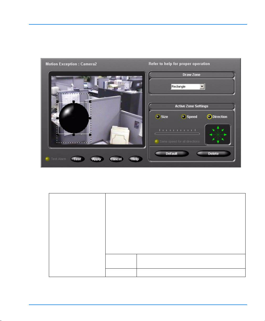
Intellex DV16000 Digital Video Management System
5. Click Setup and the Motion Exception screen appears. A segment must be
defined for the Setup button to be displayed. For more information on defining a
segment, refer to Defining a New Segment on page 60.
Figure 1 — Motion Exception Screen
The following table describes the components of the Motion Exception screen:
Draw Zone Defines the target area for the alarm or filter. The defined
object must fit within this target area. The Active Zone is
the currently selected target area that has scrolling
borders; any inactive target area has static borders.
NOTE: If you define multiple target areas, the areas may
overlap, but not completely.
To change between target areas, click the target area you
wish to work with. Any changes you make then apply
only to the Active Zone (i.e., the selected target area).
Shape The pull-down menu allows you to define a
rectangle, an ellipse, or a custom shape.
Undo Click to cancel the last action performed.
Setup Options 79

Installation and Operating Instructions
Active Zone
Settings
(page 81)
NOTE: You can use the default settings for size, speed
and direction by drawing a target area without
specifying size, speed or direction for the object.
The default settings will trigger an alarm for
virtually any
type of motion in the target area. You
can adjust these settings independently of each
other to reduce the number of objects that trigger
alarms.
Size Defines the minimum size of the object in
the target area. Anything larger than the
defined area triggers an alarm.
Speed Defines the slowest speed of the object
passing through the target area. Anything
faster than this speed triggers an alarm. The
default speed is no movement.
Direction Defines the direction of the object passing
through the target area. When an arrow is
green, the indicated direction is enabled.
When an arrow is grayed out, the indicated
direction is disabled. The default direction
is all directions enabled.
Delete Removes the Active Zone (i.e., the selected
target area with scrolling borders).
Default Completely resets all the default settings
(size, speed, and direction) for the Active
Zone.
Motion Exception Displays the image from the selected camera.
Te s t Allows you to test the current filter settings
(see Te st i n g on page 82).
Apply Click to apply the changes made.
Cancel Click to cancel the changes made.
Help Click to display online help for this screen.
80 Setup Options

Active Zone Settings
When setting up Motion Exception filters to search for or filter an event or a number
of events, we recommend that you create a number of target areas for the selected
camera. Most camera placements and the environments in which cameras operate
will record video that exhibits wide variations. Therefore, it will be helpful to create
multiple target areas, in order to account for the size and speed of objects within each
target area and to exclude sources of environmental noise or unwanted object motion.
NOTE: If you define multiple target areas in one image area, the target areas may
overlap, but not completely.
Size
After the target area is drawn, a default object size is created. Motion Exception
searches for any object within the target area that exceeds this size. To change the
minimum size of the object, click the Size button. To preserve the object’s aspect ratio,
use the slider bar to define the size of your object. Use the handles on the corners of
the object to change both
size with this method does not preserve the aspect ratio. After specifying the size,
Motion Exception then looks for any object larger
width) than the minimum size. Any object larger than the minimum size will trigger
an alarm.
Speed
Intellex DV16000 Digital Video Management System
the size and the aspect ratio by dragging a corner. Changing
in both dimensions (height and
In each active direction, you may define a minimum speed. For example, you may set
a walking pace speed as the minimum speed limit for objects moving left, but a
running pace speed the minimum speed limit for objects moving right. After you
select the Speed button, the object starts to move in the active direction. To change
the object’s direction, click the appropriate direction arrow. The current live video for
the active camera is displayed beneath the object to show you an accurate gauge for
the speed. If you select the Same speed for all directions button, any speed
adjustments that you make will then apply to ALL directions selected.
Direction
To specify the direction(s) in which the object must be moving,
select the Direction button. The eight direction arrows are now
active. Click on each of the direction arrows to enable or disable a
direction. An object’s direction is defined by the 45° sector into
which the object’s movement falls. By enabling multiple sectors,
you expand the possible range of directions in which an object’s
movement may be tracked. If you are searching for motion in one
direction, select more than one arrow in that range of directions to account for
variations in tracking the object’s motion.
Setup Options 81

Installation and Operating Instructions
Te st i n g
After you have configured a Motion Exception filter, click the Test button to enable
the Test mode. If the Motion Exception filter is triggered, the Test Alarm LED lights
up for five seconds and the target area where the filter was applied is activated. All
the Active Zone Settings options are disabled until you exit Test mode by clicking the
Test button again.
To use Motion Exception
From the Main menu:
1. From the main screen or the playback screen, click the Search button. The Mode
tab appears.
2. Select With Image Filters.
3. Click the Filters tab.
4. Select the appropriate camera from the Camera pull-down menu.
5. Select Motion Exception from the Filters pull-down menu.
6. Click Setup and the Motion Exception screen appears.
7. Click the Shape pull-down menu and select Ellipse, Rectangle or Custom shape.
Define an Active Zone in the image area using the mouse to draw the shape.
8. Click the Size button. Define the size of the object by dragging one of the corner
handles or by using the slide bar.
NOTE: Anything larger than this object triggers an alarm.
9. Click the Speed button and set the slowest speed of the object using the slider bar.
Select whether you want to have the same speed for all directions.
NOTE: Anything moving faster than this object triggers an alarm.
10. Click the Direction button. On the direction compass, select the direction arrow(s)
to be enabled.
11. Click Apply.
From the Setup menu:
1. From the main screen, click the Setup button. The Setup Options screen appears.
2. Click the Schedule button. The Mode tab (the first Schedule Setup screen)
appears.
3. Select the Use Regular Schedule or the Use Custom Schedule option.
4. Click the Camera 1-8 or 9-16 tab.
5. Move the mouse pointer over either the Day Filter or the Night Filter next to a
camera name.
6. Click the down arrow and select Motion Exception.
82 Setup Options

Intellex DV16000 Digital Video Management System
7. Click Setup and the Motion Exception screen appears.
8. Click the Shape pull-down menu and select either an ellipse, a rectangle or a
custom shape. Define an Active Zone in the image area.
9. Click the Size button. Define the size of the object by dragging one of the corner
handles or by using the slide bar.
NOTE: Anything larger than this object triggers an alarm.
10. Click the Speed button and set the slowest speed of the object using the slide bar.
Select whether you want to have the same speed for all directions.
NOTE: Anything moving faster than this object triggers an alarm.
11. Click the Direction button. On the direction compass, select the direction arrow(s)
to be enabled.
Setup Options 83
Installation and Operating Instructions
Environmental Factors
Several factors may reduce the effectiveness of object tracking when using Motion
Exception. Here are some environmental and object recommendations to help you set
up your cameras using Motion Exception.
NOTE: The optimal setting is a well lit area, a motionless background, and a camera
recording rate of at least 7.5 ips.
Background motion Select a location with no continual motion in the
Lighting Sudden lighting changes, such as turning lights on or
Objects moving too
fast
Reflections Reflections of objects in windows, mirrors or other
background. For example, do not place the camera
facing trees that are moving in the wind, a high traffic
roadway, a TV monitor, etc.
off, may trigger unwanted alarms.
Avoid low light conditions and harsh shadows.
If there is too little contrast between an object in the
foreground and its background, this is usually due to
poor lighting.
Because the Intellex software interprets changes in an
object’s position over time, a fast-moving object may
not be tracked accurately.
surfaces will be interpreted as another object. If
possible, place the camera so that there are no
reflective surfaces in the camera’s field of view.
84 Setup Options
 Loading...