

Page 1
INT-HD52 Owners Manual
Rev 170724
11675 Ridgeline Drive
Colorado Springs, CO
80918
Phone: 719-260-0061
Toll-Free: 800-530-8998
Fax: 719-260-0075
Page 2

INT-HD52 Owners Manual
2
Page 3

INT-HD52 Owners Manual
Important Safety Instrucons
» Please completely read and verify you understand all instrucons in this manual before operang this equipment.
» Keep these instrucons in a safe, accessible place for future reference.
» Heed all warnings.
» Follow all instrucons.
» Do not use this apparatus near water.
» Clean only with a dry cloth.
» Do not install near any heat sources such as radiators, heat registers, stoves, or other apparatus (including ampliers)
that produce heat.
» Use only accessories specied or recommended by Intelix.
» Explanaon of graphical symbols:
◊ Lightning bolt/ash symbol: the lightning bolt/ash and arrowhead within an equilateral triangle
symbol is intended to alert the user to the presence of uninsulated “dangerous voltage” within the
product enclosure which may be of sucient magnitude to constute a risk of shock to a person or
persons.
◊ Exclamaon point symbol: the exclamaon point within an equilateral triangle symbol is intended
to alert the user to the presence of important operang and maintenance (servicing) instrucons
in the literature accompanying the product.
» WARNING: TO REDUCE THE RISK OF FIRE OR ELECTRIC SHOCK, DO NOT EXPOSE THIS APPARATUS TO RAIN OR
MOISTURE AND OBJECTS FILLED WITH LIQUIDS, SUCH AS VASES, SHOULD NOT BE PLACED ON THIS APPARATUS.
» Use the mains plug to disconnect the apparatus from the mains.
» THE MAINS PLUG OF THE POWER CORD MUST REMAIN READILY ACCESSIBLE.
» Do not defeat the safety purpose polarized or grounding-type plug. A polarized plug has two blades with one wider
than the other. A grounding-type plug has two blades and a third grounding prong. The wide blade or the third prong
is provided for your safety. If the provided plug does not t into your outlet, consult an electrician for replacement of
your obsolete outlet. Cauon! To reduce the risk of electrical shock, grounding of the center pin of this plug must be
maintained.
» Protect the power cord from being walked on or pinched parcularly at the plugs, convenience receptacles, and the
point where they exit from the apparatus.
» Do not block the air venlaon openings. Only mount the equipment per Intelix’s instrucons.
» Use only with the cart, stand, table, or rack specied by Intelix or sold with the equipment. When/if a
cart is used, use cauon when moving the cart/equipment combinaon to avoid injury from p-over.
» Unplug this apparatus during lightning storms or when unused for long periods of me.
» Cauon! Shock Hazard. Do not open the unit.
» Refer to qualied service personnel. Servicing is required when the apparatus has been damaged in any way, such as
power supply cord or plug is damaged, liquid has been spilled or objects have fallen into the apparatus, the apparatus
has been exposed to rain or moisture, does not operate normally, or has been dropped.
3
Page 4

INT-HD52 Owners Manual
Table of Contents
Product Overview ��������������������������������������������������������������������������������������������������������������������������������������� 6
Package Contents ��������������������������������������������������������������������������������������������������������������������������������������� 6
Front and Rear Panels ��������������������������������������������������������������������������������������������������������������������������������� 7
Front Panel ���������������������������������������������������������������������������������������������������������������������������������������������������� 7
Rear Panel ����������������������������������������������������������������������������������������������������������������������������������������������������� 8
IR Remote ��������������������������������������������������������������������������������������������������������������������������������������������������� 9
Installaon Instrucons ���������������������������������������������������������������������������������������������������������������������������� 10
Quick Start ��������������������������������������������������������������������������������������������������������������������������������������������������10
Mount the Switching Scaler ������������������������������������������������������������������������������������������������������������������������10
Connecng Sources ������������������������������������������������������������������������������������������������������������������������������������� 10
HDMI / Display Port Input ....................................................................................................................10
VGA/Analog Video Inputs .....................................................................................................................10
Connecng Displays ������������������������������������������������������������������������������������������������������������������������������������ 11
HDMI Output ........................................................................................................................................11
HDBaseT Output ................................................................................................................................... 11
Connecng Microphone Input ��������������������������������������������������������������������������������������������������������������������11
Connect Audio Output ���������������������������������������������������������������������������������������������������������������������������������11
Connect IR Control ��������������������������������������������������������������������������������������������������������������������������������������12
Source Device and Scaler Control via Remote IR ..................................................................................12
Remote Display and Scaler Control via Local IR ....................................................................................12
Apply Power ������������������������������������������������������������������������������������������������������������������������������������������������12
Applicaon Diagram �������������������������������������������������������������������������������������������������������������������������������� 13
On Screen Display (OSD) Menu Navigaon ����������������������������������������������������������������������������������������������� 14
Opons Menu ���������������������������������������������������������������������������������������������������������������������������������������������14
Output Adjust .......................................................................................................................................14
Input5 Select ........................................................................................................................................14
Baud Rate .............................................................................................................................................14
User EDID Upload(USB) ........................................................................................................................14
Soware Update...................................................................................................................................14
Picture Menu �����������������������������������������������������������������������������������������������������������������������������������������������15
Picture Mode ........................................................................................................................................ 15
Color Temperature ...............................................................................................................................15
Aspect Rao .........................................................................................................................................15
Noise Reducon (HDMI Only) ..............................................................................................................15
Screen (VGA) ........................................................................................................................................15
Color Range (VGA) ................................................................................................................................15
Setup Menu ������������������������������������������������������������������������������������������������������������������������������������������������� 16
Setup Menu ������������������������������������������������������������������������������������������������������������������������������������������������� 16
OSD Language.......................................................................................................................................16
Restore Factory Default ........................................................................................................................16
Blending................................................................................................................................................16
HDMI CEC .............................................................................................................................................16
OSD Duraon ........................................................................................................................................16
Version .................................................................................................................................................. 16
4
Page 5

INT-HD52 Owners Manual
Web Graphical User Interface (GUI) Control ���������������������������������������������������������������������������������������������� 17
Control Menu ���������������������������������������������������������������������������������������������������������������������������������������������� 18
Source ���������������������������������������������������������������������������������������������������������������������������������������������������������18
VGA ....................................................................................................................................................... 18
DP .........................................................................................................................................................18
VOLUME ...............................................................................................................................................18
POWER FUNCTIONS .............................................................................................................................18
Conguraon Menu ������������������������������������������������������������������������������������������������������������������������������������ 19
Conguraon; Seng ��������������������������������������������������������������������������������������������������������������������������������� 19
Output Resoluon ................................................................................................................................19
Update .................................................................................................................................................. 19
Shutdown Timer (No Input) ..................................................................................................................19
Conguraon; Network ������������������������������������������������������������������������������������������������������������������������������20
Conguraon; Source Label ������������������������������������������������������������������������������������������������������������������������ 20
RS232 Control Menu �����������������������������������������������������������������������������������������������������������������������������������21
Port ....................................................................................................................................................... 21
Baud Rate .............................................................................................................................................21
Command ............................................................................................................................................. 21
Password Menu ������������������������������������������������������������������������������������������������������������������������������������������22
Web Graphical User Interface (GUI) Update ���������������������������������������������������������������������������������������������� 22
RS232 Commands ������������������������������������������������������������������������������������������������������������������������������������� 23
Video Input Switching and Conguraon ���������������������������������������������������������������������������������������������������23
Video Input Customizaon ��������������������������������������������������������������������������������������������������������������������������24
Video Input HDCP Compliance ��������������������������������������������������������������������������������������������������������������������24
Video Output Conguraon ������������������������������������������������������������������������������������������������������������������������ 25
Video Output Adjustment ���������������������������������������������������������������������������������������������������������������������������25
Freeze Video Output������������������������������������������������������������������������������������������������������������������������������������26
Audio Input Conguraon and Adjustment ������������������������������������������������������������������������������������������������26
Audio Output Control ���������������������������������������������������������������������������������������������������������������������������������� 26
CEC Setup and Control ��������������������������������������������������������������������������������������������������������������������������������27
Menu Navigaon ����������������������������������������������������������������������������������������������������������������������������������������27
OSD Visibility ����������������������������������������������������������������������������������������������������������������������������������������������� 27
System Query ����������������������������������������������������������������������������������������������������������������������������������������������28
System Query (connued) ���������������������������������������������������������������������������������������������������������������������������29
System Power / Factory Default ������������������������������������������������������������������������������������������������������������������29
Troubleshoong ��������������������������������������������������������������������������������������������������������������������������������������� 30
Presentaon Switcher does not power on ��������������������������������������������������������������������������������������������������30
No video from HDBaseT output ������������������������������������������������������������������������������������������������������������������30
Distorted or no video output �����������������������������������������������������������������������������������������������������������������������30
Cannot hear HDMI input audio ������������������������������������������������������������������������������������������������������������������� 30
Presentaon Switcher does not automacally switch ��������������������������������������������������������������������������������30
Technical Specicaons ���������������������������������������������������������������������������������������������������������������������������� 31
5
Page 6

INT-HD52 Owners Manual
Product Overview
The Intelix INT-HD52 is a compact auto switcher scaler that allows the integraon of analog and digital devices
into a high-denion environment. Mounng opons include under table or resng on a shelf.
The INT-HD52 allows selecon of ve dierent sources, and will simultaneously scale the selected video to
HDMI and HDBaseT outputs. The unit features three HDCP compliant HDMI inputs, one Display Port input
and one VGA input. The VGA input can be congured to support YPbPr (component), YC (S-video), and C
(composite) video formats with the appropriate VGA breakout cable. There are eight xed output resoluons
to choose from, and several aspect rao modes, which will ensure your content is displayed properly. The
HDBaseT output will allow you to extend audio, video, and control signals up to 70m away.
The INT-HD52 oers unique audio opons designed to simplify your installaon. All audio inputs are embedded
into the HDMI and HDBaseT streams, so you can use your display speakers for audio. Addionally, the balanced
stereo audio output can be used for audio reinforcement. A balanced input is provided (line or microphone
level) which is mixed with the source audio to provide voice li capabilies; while the volumes of the mic and
source can be individually controlled.
The INT-HD52 can be controlled in many dierent ways. When the VGA input is dened as a PC signal input,
the INT-HD52 can be congured to automacally switch to an input once connected to the switcher; once a
device is removed, INT-HD52 will switch to the rst acve input with HDMI inputs taking priority. The front
panel oers source selecon and volume control. Third party control systems can ulize RS232 or Ethernet
ports on the rear panel, RS232 extended (with a compable HDBaseT receiver with RS232 throughput), and
rear panel IR control. CEC enabled source and display devices can also be controlled from the INT-HD52..
Package Contents
• (1) Intelix INT-HD52 Switcher Scaler
• (2) Mounng Ears with 4 Screws
• (1) Power Adapter (24VDC, 2.71A)
• (4) Plasc Cushions+
• (1) IR Remote
• (1) VGA Analog Breakout Cable (VGA to YPbPr)
• (1) RS232 DB9 - 3 Pin Phoenix Breakout Cable
• (2) 3 Pin Phoenix Connectors
• (1) 5 Pin Phoenix Connector
• (1) IR Emier
• (1) IR Receiver
• (1) Quick Install Guide
6
Page 7

Front Panel
1
Front and Rear Panels
2 3 4 5 6
7 8
INT-HD52 Owners Manual
7
8 9
1. Built in IR Receiver
2. Power Indicator - GREEN when device is in standby mode, RED when device is powered on and no indicator when there is
no power to device
3. 1-HDMI/MHL input selector and acvity LED / Le Key for On screen display control (OSD)
4. 2-HDMI input selector and acvity LED / Right Key for OSD
5. 3-HDMI input selector and acvity LED / Up Key for OSD
6. 4-Display Port input selector and acvity LED / Down Key for OSD
7. 5-VGA input selector and acvity LED / Enter Key for OSD
8. Auto Switching selector and acvity LED- Press this to enter / exit auto-switching mode / OSD menu buon
• NOTE: When you set the VGA input port to C-Video or YPbPr in Manual-switching mode, the system will not be able to enter
auto-switching mode.
• Hold this buon down for 3 seconds to enter On Screen Display menu (OSD)
9. Volume knob for variable audio control- Push knob in to toggle between ‘Mic’ and ‘Source’ control
10
7
Page 8
INT-HD52 Owners Manual
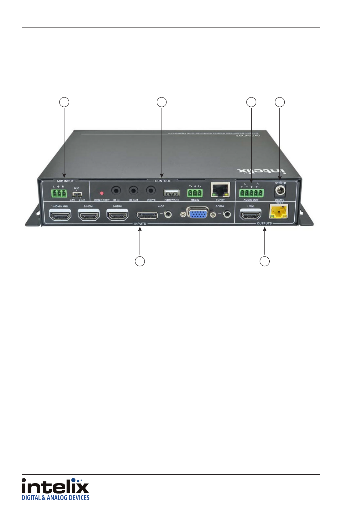
Rear Panel
3 4
1
5 6
2
1. INPUTS
• Video input ports: 1 HDMI/MHL, 2 HDMI inputs, 1 Display Port and 1 VGA
• Audio input ports: 1 Display Port external audio input and 1 VGA auxiliary audio input
2. OUTPUTS
• HDMI output: HDMI video output port
• HDBaseT output: Supports PoH. Connect to a compable HDBaseT receiver to transmit A/V, IR and RS232 control
3. MIC INPUT
• Mic audio port connects to microphone
• Dial switch- switches between 3 dierent modes; 48V for condenser mics, MIC mode for dynamic mics and LINE mode for
line level audio
4. CONTROL
• RES RESET - press this to reset output resoluon to 720p or to acvate HDMI and HDBT outputs if they have been turned o
• IR IN / IR OUT - connect with IR receiver and emier to control devices via IR
• FIRMWARE - Type-A USB port for updang rmware
• RS232 - Serial port, connect a control device to control the INT-HD52
• TCP/IP - Ethernet port, connect a control device or computer to control INT-HD52
5. AUDIO OUTPUT
• Stereo balanced L/R audio output
6. DC 24V
• Locking power port, connect DC 24V power adapter
8
Page 9
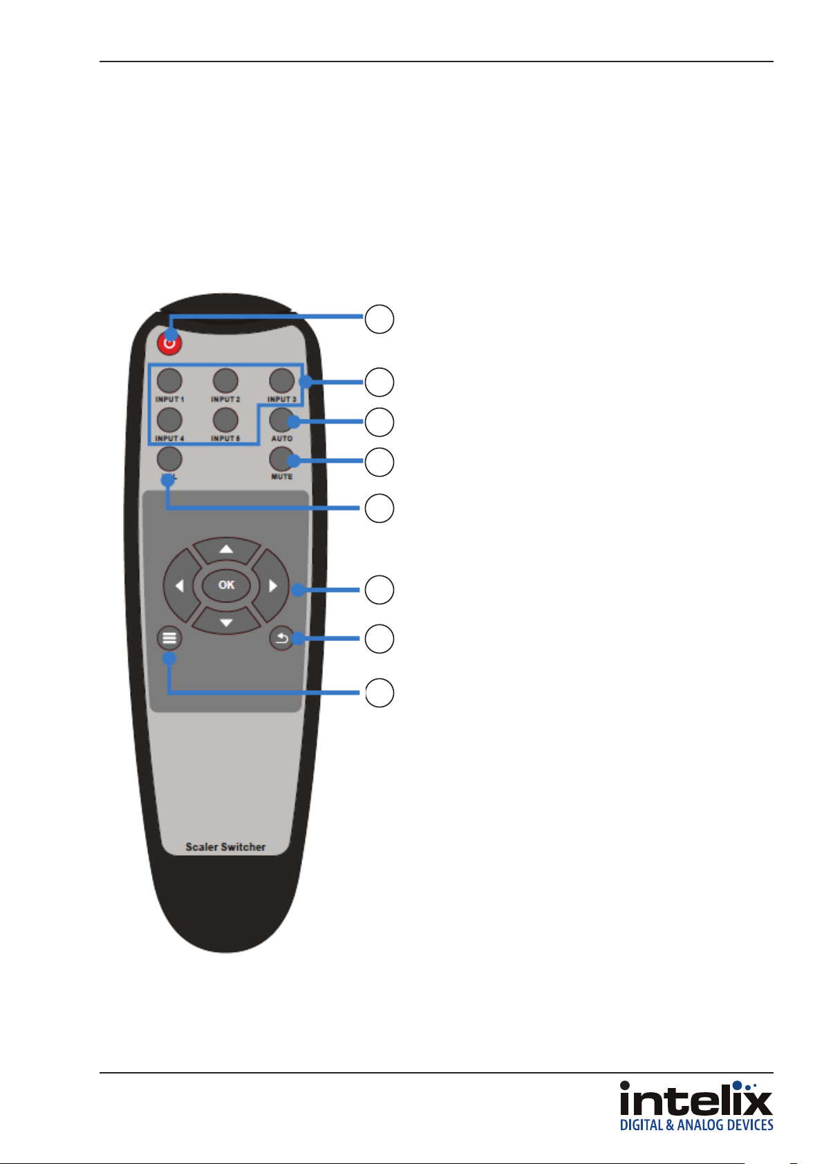
IR Remote
The included IR remote performs all of the funcons available on the front panel.
The remote control requires two AAA baeries, which are included.
1. Power on/o
1
2
3
4
2. Input source select buons
3. Enter / Exit audio switching mode
4. Audio mute
5. Volume - Aer pressing this buon a volume
adjustment screen will shown on display
connected to INT-HD52, then press UP/DOWN to
adjust volume
6. Navigaon. OK = enter or conrm
7. Exit: terminates current operaon
8. OSD menu, also returns to previous menu
INT-HD52 Owners Manual
5
6
7
8
9
Page 10

INT-HD52 Owners Manual
Installaon Instrucons
Quick Start
1. Mount the switching scaler
2. Connect sources
3. Connect displays
4. Connect microphone input (oponal)
5. Connect audio output (oponal)
6. Connect control (oponal)
7. Apply power
Mount the Switching Scaler
At least 2 inches of free air space is required on both sides of the INT-HD52 for proper side venlaon. Avoid
mounng the INT-HD52 near a power amplier or any other source of signicant heat.
For shelf mounng, aach the supplied shelf feet to the boom of the INT-HD52.
For table mounng, aach the supplied mounng rails to the sides of the INT-HD52. Once the rails are installed,
the scaler is ready to be mounted under a table.
Connecng Sources
HDMI / Display Port Input
Connect the source devices to HDMI or Display Port inputs using HDMI / Display Port cables that are less than
or equal to 5 meters in length. For source devices that are further away, an extension device will be required
to complete the connecon.
VGA/Analog Video Inputs
Connect the source devices to VGA inputs using VGA cables that are less than or equal to 5 meters in length.
For source devices that are further away, a VGA extension device will be required to complete the connecon.
Use the supplied adapter cable (FLX-RBOCA) if the source is an analog video signal such as component or
composite video (yellow connector on source to red connector on FLX-RBOCA).
10
Page 11

INT-HD52 Owners Manual
TIA/EIA-568B
1 8
Connecng Displays
HDMI Output
Connect the display devices to HDMI outputs using HDMI cables that are less than or equal to 5 meters in
length. For display devices that are further away, it is highly recommended to ulize the HDBaseT output.
HDBaseT Output
Connect the HDBaseT receiver to the display per the manufacturer’s instrucons. Connect the HDBaseT cable
to the scaler and the HDBaseT receiver.
For all HDBaseT cabling, the EIA/TIA-568B crimp paern must
Orange/White
Pin 1
Pin 2
Pin 3
Pin 4
Pin 5
Pin 6
Pin 7
Pin 8
Orange
Green/White
Blue
Blue/White
Green
Brown/White
Brown
be used on Category 6 or greater cable. In areas with large
amounts of electromagnec (EM) or radio frequency (RF)
interference, a shielded variety of Category 5e or greater cable
is recommended with shielded connectors on both ends of the
selected cable.
The HDBaseT output provides 15 was of Power over Ethernet,
which eliminates the need for a power supply with a compable
HDBaseT receiver. Intelix recommends using the DIGI-HD60C-R
or DIGI-HD60-R for installaons which require remote power.
Connecng Microphone Input
Insert the removable 3-pin phoenix connector block to the MIC input.
Set the MIC switch to the proper seng for the microphone input source.
48V 48V phantom power
MIC No phantom power
LINE No gain needed
Connect Audio Output
Insert the removable 5-pin phoenix connector block to the audio output. The INT-HD52 supports a stereo
balanced le and right output.
L+
L-
R+
R-
L+
L-
R+
R-
11
Page 12

INT-HD52 Owners Manual
Connect IR Control
The INT-HD52 has an advanced bidireconal IR control protocol through the HDBaseT output port, which
allows for the control of the sources, displays, and presentaon switcher. Intelix recommends using the INTHD70-RX or the DIGI-BSR-4K for installaons which require IR extension.
Only use the included IR receiver and emier and transmier. Third party 12V DC IR components are not
compable with the INT-HD52.
Source Device and Scaler Control via Remote IR
An IR signal passed from the display locaon through the HDBaseT connecon can provide control of the
source device. The IR signal from the remote display locaon can also control the switching of the switcher /
scaler.
Aach the plasc end of the IR emier to the IR receiver of the source device. Insert the TS 3.5 mm plug of the
emier to the IR output port (IR OUT) of the switching scaler for the source device to control.
Remote Display and Scaler Control via Local IR
An IR signal may be passed to a remote display locaon through the HDBaseT connecon. In order to control
the INT-HD52 via IR or extend an IR signal to a remote display, the included IR receiver must be connected to
the IR input port (IR IN) of the switcher / scaler.
Apply Power
Plug the power supply into the power input port on the rear of the switcher / scaler. Twist the locking ring
clockwise to prevent accidental disconnecon of power.
12
Page 13

INT-HD52 5X1 PRESENTATION SWITCHER
Applicaon Diagram
REMOTE
MIC
CONTROL SYSTEM
WIRED
BYOD
DVD
INT-HD52 Owners Manual
AUDIO AMPLIFIER
HDMI
CATx
DP
VGA
AUDIO
IR
RS232
WIRELESS
BYOD
LAPTOP
LEGACY
COMPUTER
up to 70m / 230’
INT-HD70-RX
HDBT RECIEVER
(Not Included)
PROJECTOR
DISPLAY
13
Page 14

INT-HD52 Owners Manual
On Screen Display (OSD) Menu Navigaon
The menu system of the INT-HD52 provides a wide array of opons to customize the installaon of the product
regardless of customer needs.
Upon entering the menu, navigang le or right will provide three dierent sub-menus: Opons, Picture and
Setup. Pressing ENTER on the front panel or OK on the remote will cycle through opons or enter another
menu if mulple conguraon sengs are available.
Opons Menu
Output Adjust
Selecng Output Adjust will open another menu which will change the vercal / horizontal posion, width, and
height of the output image. The default value is O. Pressing right or le will cycle to On. Values range from 0
to 100. Pressing MENU will exit the sub-menu.
HDMI and HDBasetT output ports can also be turned ON/OFF under this menu seng.
Input5 Select
Pressing ENTER or OK will cycle the analog video input modes: VGA, YPbPr (component video), and AV
(composite video).
Baud Rate
Pressing ENTER or OK will allow you to change the baud rate seng of the RS232 control.
User EDID Upload(USB)
Load user dened EDID table into switcher / scaler through this menu. You will need to have the EDID table
saved on to a portable USB drive to use this feature. Portable USB drive will use the rmware USB port on the
INT-HD52 to upload the EDID table.
Soware Update
A separate document will provide usage instrucons once a new soware update is available.
14
Page 15

Picture Menu
Picture Mode
INT-HD52 Owners Manual
Selecng Picture Mode will open another menu which will change the contrast, brightness, color, and sharpness
of the input image. The default value is Standard. Values range from 0 to 100. Pressing MENU will exit the submenu.
Color Temperature
Selecng Color Temperature will open another menu which will change the color temperature of the input
image. The default value is Medium. Values range from 0 to 100. Pressing MENU will exit the sub-menu.
Aspect Rao
Selecng Aspect Rao will open another menu which will change the aspect rao of the input image. The
default value is Nave. While VGA only has three aspect rao selecons available, HDMI has seven. Pressing
MENU will exit the sub-menu.
VGA and HDMI: Nave, 4:3, 16:9
HDMI only: Zoom 1, Zoom 2, Just Scan, Panorama
Noise Reducon (HDMI Only)
Selecng Noise Reducon will open another menu which will compensate for compression noise of
the input image. Available selecons are: O, Low, Middle, High, and Default. Pressing MENU will exit
the sub-menu.
Screen (VGA)
Selecng Screen will open another menu which will adjust the input signal processing to clear up various
analog distoron issues. Auto Adjust will automacally correct for any input signal issues. Manual adjustments
include Horizontal Posion, Vercal Posion, Size, and Phase where values range from 0 to 100. Pressing MENU
will exit the sub-menu.
Color Range (VGA)
Selecng Color range will cycle between two opons: 0-255 (deep color) and 16-235 (standard color).
15
Page 16

INT-HD52 Owners Manual
Setup Menu
Setup Menu
The Setup menu features on-screen display (OSD) language selecon, OSD blending (transparency), HDMI CEC,
and OSD duraon.
OSD Language
Selecng OSD Language will open another menu which will change the menu language of the INT-HD52.
The available languages are: English, German, Russian, Chinese, French, Spanish, and Swedish. The default
language is English. Pressing MENU will exit the sub-menu.
Restore Factory Default
This menu will allow you to reset the INT-HD52 back to factory default
Blending
Selecng Blending will open another menu which will present opons the menu transparency. The available
opons are O, Low, Middle, and High where the default is O. Pressing MENU will exit the sub-menu.
HDMI CEC
Selecng HDMI CEC will open another menu which will present opons to adjust the operaon of CEC. Device
List will show which HDMI devices support CEC. Cycling HDMI CEC in the sub-menu will turn on or o CEC
support. Cycling Auto Standby will enable or disable this feature. Pressing MENU will exit the sub-menu.
OSD Duraon
Selecng OSD Duraon will open another menu to select the period of me the input name will be visible aer
switching sources. Available mes are O, 5Sec, 10Sec, and 15Sec. The default is O. Pressing MENU will exit
the sub-menu.
Version
Displays current soware
16
Page 17

INT-HD52 Owners Manual
Web Graphical User Interface (GUI) Control
The INT-HD52 can be controlled by web-based GUI which allows users to interact the INT-HD52 through
graphical icons and visual indicators.
Connect a computer and the INT-HD52 to a Ethernet switch using the Ethernet ports on your
computer and the INT-HD52. Type 192.168.0.178 in a web browser on the computer to access the
web GUI. When prompted enter ‘user’ as the user name and password and clock LOGIN.
17
Page 18

INT-HD52 Owners Manual
Control Menu
Source
Click on desired video input source
VGA
Click ADJUST to adjust the posion of the VGA output image
DP
Click AUDIO to turn on/o the Display Ports external audio input
VOLUME
Click the corresponding posive / negave buons to increase / decrease the volume of the microphone or
source audio input. Click the corresponding MUTE buon to mute / unmute microphone or source audio input.
POWER FUNCTIONS
Click SOURCE to turn on/o source device
Click DISPLAY to turn on/o display device
Click LOCAL to put the INT-HD52 into standby mode
18
Page 19

INT-HD52 Owners Manual
Conguraon Menu
Click on the in the control menu to access the conguraon menu. The conguraon menu oers three
sub-menus; Sengs, Network and Source Label.
Conguraon; Seng
Output Resoluon
Select the desired output resoluon and click CONFIRM
Update
Insert a portable USB drive containing the EDID / rmware le into the FIRMWARE port on the INT-HD52 then
click EDID or FIRMWARE to update
Shutdown Timer (No Input)
If the INT-HD52 does not detect a present video signal it will automacally shut down aer the preset me
interval has passed. AUTO drop down menu sets the me interval for auto switching mode and MANU drop
down sets the me interval for manual switching mode
19
Page 20

INT-HD52 Owners Manual
Conguraon; Network
In this menu you can change the IP address of the INT-HD52. Select DHCP if you desire the IP to be set
automacally based on your DHCP network sengs or select STATIC IP mode to manually enter in the IP
Address, Subnet Mask and Gateway. When you manually enter in the IP address make sure you the address
does not overlap an exisng IP address in the same network.
Conguraon; Source Label
In this menu you can change the name of the source inputs as desired.
20
Page 21

RS232 Control Menu
INT-HD52 Owners Manual
Port
Select the receiving control port by choosing LOCAL for the INT-HD52 RS232 port or HDBT for a compable
HDBaseT receiver with RS232 through port.
Baud Rate
The baud rate of the LOCAL port cannot be changed however the HDBT port can be modied. The compable
baud rates for the HDBaseT port are 2400, 4800, 9600, 19200, 38400, 57600 and 115200.
Command
Typing an ASCII format command into this eld will control external devices connected to the INT-HD52 RS232
port or HDBaseT device.
21
Page 22

INT-HD52 Owners Manual
Password Menu
In this menu the user name and password can be changed. Click CONFIRM when user name and password has
been changed as desired.
Web Graphical User Interface (GUI) Update
Connect a computer and the INT-HD52 to a Ethernet switch using the Ethernet ports on your
computer and the INT-HD52. Type hp://192.168.0.178:100 in a web browser on the computer to
access the web GUI update portal. When prompted enter ‘user’ as the user name and password.
Then click ADMINISTRATION on the menu to the le and click UPLOAD PROGRAM as shown below
Browse to nd the correct update le and click APPLY, the INT-HD52 will begin to update.
22
Page 23

RS232 Commands
RS232 Sengs: 9600 baud, 8 Data bits, 1 Stop bit, Parity = None
There are no spaces between any of the characters in the command string.
<CR> = Carriage return (Hex 0D)
<LF> = Line Feed (Hex 0A)
Video Input Switching and Conguraon
Descripon Command Response
Select HDMI 1 input (input 1)
Select HDMI 2 input (input 2)
Select HDMI 3 input (input 3)
Select Display Port input (input 4)
Select VGA input (input 5)
Auto switch inputs on
Auto switch inputs o
Set VGA (Input 5) for VGA video
Set VGA (Input 5) for YPbPr video
Set VGA (Input 5) for composite video
50701% Switch to HDMI 1<CR><LF>
50702% Switch to HDMI 2<CR><LF>
50703% Switch to HDMI 3<CR><LF>
50704% Switch to DP<CR><LF>
50705% Switch to VGA 1/YPbPr/AV <CR><LF>
50785% Auto Switching<CR><LF>
50786% Manual Switching<CR><LF>
50683%
50684%
50685%
Input 5 Set & Switch to VGA <CR><LF> AND
Switch to VGA <CR><LF>
Input 5 Set & Switch to YPbPr <CR><LF> AND
Switch to YPbPr <CR><LF>
Input 5 Set & Switch to AV <CR><LF> AND
Switch to AV <CR><LF>
INT-HD52 Owners Manual
23
Page 24

INT-HD52 Owners Manual
Video Input Customizaon
Descripon Command Response
Aspect Ratio : 16:9<CR><LF> OR
Aspect Ratio : 4:3<CR><LF> OR
Aspect Ratio : auto<CR><LF> OR
Cycle aspect rao
Set brightness to XX; XX = 00 to 99
Set contrast to XX; XX = 00 to 99
Set saturaon to XX; XX = 00 to 99
Set sharpness to XX; XX = 00 to 07
Cycle color temperature
Cycle picture mode
50608%
502XX%
503XX%
504XX%
505XX%
50607%
50614%
Aspect Ratio : panorama<CR><LF> OR
Aspect Ratio : justscan<CR><LF> OR
Aspect Ratio : zoom2<CR><LF> OR
Aspect Ratio : zoom1<CR><LF>
Brightness: 50<CR><LF>
Contrast: 50<CR><LF>
Saturation: 50<CR><LF>
Sharpness: 50<CR><LF>
Color Temperature: medium<CR><LF> OR
Color Temperature: warm<CR><LF> OR
Color Temperature: user<CR><LF> OR
Color Temperature: cool<CR><LF>
Picture Mode : standard<CR><LF> OR
Picture Mode : mild<CR><LF> OR
Picture Mode : user<CR><LF> OR
Picture Mode : dynamic<CR><LF>
Video Input HDCP Compliance
Descripon Command Response
Turn on HDCP compliance on output
Turn o HDCP compliance output
50793% HDCP ON<CR><LF>
50794% HDCP OFF<CR><LF>
24
Page 25

Video Output Conguraon
Descripon Command Response
1360x768 output
1920x1200 output
1600x1200 output
1600x900 output
1024x768 output
1280x720 output
1280x800 output
1920x1080 output
Auto adjust output resoluon based on
display
50619% Resolution: 1360x768<CR><LF>
50620% Resolution: 1920x1200<CR><LF>
50621% Resolution: 1600x1200<CR><LF>
50624% Resolution: 1600x900<CR><LF>
50626% Resolution: 1024x768<CR><LF>
50627% Resolution: 1280x720<CR><LF>
50628% Resolution:1280x800<CR><LF>
50629% Resolution: 1920x1080<CR><LF>
50782% modify input hdmi preferred timing<CR><LF>
AND
rotarySwitch==57<CR><LF> AND
Manage HDMI input with preferred
timing<CR><LF> AND
timing table=[1]<CR><LF> AND
Resolution: 1920x1080<CR><LF> AND
INT-HD52 Owners Manual
Video Output Adjustment
Descripon Command Response
Enable OSD for image adjustments
Disable OSD for image adjustments
Shi image le
Shi image right
Shi image up
Shi image down
Decrease image width
Increase image width
Decrease image height
Increase image height
Enable HDMI Output
Disable HDMI Output
Disable HDBT Output
Enable HDBT Output
Enable HDMI & HDBT Output
50678% Enter Output Position Adjust<CR><LF>
50679% Exit Output Position Adjust<CR><LF>
50670% Output Position Adjust X 50 <CR><LF>
50671% Output Position Adjust X 50 <CR><LF>
50672% Output Position Adjust Y 50<CR><LF>
50673% Output Position Adjust Y 50<CR><LF>
50674% Output Width Adjust 50<CR><LF>
50675% Output Width Adjust 50<CR><LF>
50676% Output Height Adjust 50<CR><LF>
50677% Output Height Adjust 50<CR><LF>
50730% HDMI Power Off<CR><LF>
50731% HDMI Power On<CR><LF>
50732% HDBT Power Off<CR><LF>
50733% HDBT Power On<CR><LF>
50734% HDMI HDBT Power On<CR><LF>
25
Page 26

INT-HD52 Owners Manual
Freeze Video Output
Descripon Command Response
Freeze output image
Un-Freeze output image
50655% Freeze: enable<CR><LF>
50656% Freeze: disable<CR><LF>
Audio Input Conguraon and Adjustment
Descripon Command Response
Use embedded audio for DP Input
Use external audio for DP input
50706% DP Audio from Embedded<CR><LF>
50707% DP Audio from LINE<CR><LF>
Audio Output Control
Descripon Command Response
Mute Source Audio
Unmute Source Audio
Source Audio volume up
Source Audio volume down
Set Source Audio to XX; XX = 00 to 60
Mute VGA Audio
Unmute VGA Audio
Mute DP Audio
Unmute DP Audio
Mute MIC audio
Unmute MIC audio
MIC volume up
MIC volume down
50600% SOURCE Mute<CR><LF>
50601% SOURCE Unmute<CR><LF>
50602% LINE Volume: XX<CR><LF>
50603% LINE Volume: XX<CR><LF>
510XX% SOURCE Volume: XX<CR><LF>
50726% VGA Audio Mute<CR><LF>
50727% VGA Audio Unmute<CR><LF>
50728% DP Audio Mute<CR><LF>
50729% DP Audio Unmute<CR><LF>
50722% MIC Mute<CR><LF>
50723% MIC Unmute<CR><LF>
50724% MIC Volume: XX<CR><LF>
50725%
MIC Volume: XX<CR><LF>
26
Page 27

CEC Setup and Control
Descripon Command Response
Enable CEC
Disable CEC
CEC Play/pause
CEC Stop
CEC Menu
CEC Reverse (rewind)
CEC Forward
CEC Up
CEC Down
CEC Le
CEC Right
CEC Select
CEC Exit
Display Power On
Display Power O
50686% HDMI CEC ON<CR><LF>
50687% HDMI CEC OFF<CR><LF>
50901% CEC cmd: play&pause<CR><LF>
50902% CEC cmd: stop<CR><LF>
50903% CEC cmd: menu<CR><LF>
50904% CEC cmd: rev<CR><LF>
50905% CEC cmd: fwd<CR><LF>
50906% CEC cmd: up<CR><LF>
50907%
50908%
50909%
50910%
50911%
50920% Display Power On<CR><LF>
50921% Display Power Off<CR><LF>
CEC cmd: down<CR><LF>
CEC cmd: left<CR><LF>
CEC cmd: right<CR><LF>
CEC cmd: select<CR><LF>
CEC cmd: exit<CR><LF>
INT-HD52 Owners Manual
Menu Navigaon
Descripon Command Response
Menu OK
Menu LEFT
Menu RIGHT
Menu UP
Menu DOWN
Enter device menu
Menu EXIT
50609% Key: ok<CR><LF>
50610% Key: left<CR><LF>
50611% Key: right<CR><LF>
50612% Key: up<CR><LF>
50613% Key: down<CR><LF>
50616% OSD: Enter<CR><LF>
50618% OSD: Exit <CR><LF>
OSD Visibility
Descripon Command Response
Enable OSD for MIC volume bar
Disable OSD for MIC volume bar
Hide mute icon of AV audio in OSD
Display mute icon of AV audio in OSD
Hide mute icon of MIC audio in OSD
Display mute icon of MIC audio in OSD
Hide freeze icon in OSD
Display freeze icon in OSD
Enable OSD for input switching
Disable OSD for input switching
50646% Volume Icon: enable<CR><LF>
50647% Volume Icon: disable<CR><LF>
50761% LINE Mute Icon: disable<CR><LF>
50762% LINE Mute Icon: enable<CR><LF>
50763% MIC Mute Icon: disable<CR><LF>
50764% MIC Mute Icon: enable<CR><LF>
50765% Freeze Icon: enable<CR><LF>
50766% Freeze Icon: disable<CR><LF>
50644% Input Icon: enable<CR><LF>
50645% Input Icon: disable<CR><LF>
27
Page 28

INT-HD52 Owners Manual
System Query
Descripon Command Response
Check volume level
Check input source
Check output resoluon
Check picture mode
Check aspect rao
Check brightness
Check contrast
Check saturaon
Check sharpness
Check color temperature
Check Line audio mute status
Check MIC mute status
Check HDMI audio inputs
Check Freeze output image status
50630%
50631%
50632%
50633%
50635%
50636% Brightness: 50<CR><LF>
50637% Contrast: 50<CR><LF>
50638% Saturation: 50<CR><LF>
50639% Sharpness: 50<CR><LF>
50640% Color Temperature: medium<CR><LF>
50751%
50752%
50712%
50753%
LINE Volume: XX<CR><LF> AND
MIC Volume: XX<CR><LF>
Input: HDMI 1<CR><LF> OR
Input: HDMI 2<CR><LF> OR
Input: HDMI 3<CR><LF> OR
Input: VGA 1<CR><LF> OR
Input: VGA 2<CR><LF>
Resolution: 1360x768<CR><LF> OR
Resolution: 1920x1200<CR><LF> OR
Resolution: 1600x1200<CR><LF> OR
Resolution: 1024x768<CR><LF> OR
Resolution: 1280x720<CR><LF> OR
Resolution:1280x800<CR><LF> OR
Resolution: 1920x1080<CR><LF>
Picture Mode : standard<CR><LF> OR
Picture Mode : mild<CR><LF> OR
Picture Mode : user<CR><LF> OR
Picture Mode : dynamic<CR><LF>
Aspect Ratio : 16:9<CR><LF> OR
Aspect Ratio : 4:3<CR><LF> OR
Aspect Ratio : auto<CR><LF> OR
Aspect Ratio : panorama<CR><LF> OR
Aspect Ratio : justscan<CR><LF> OR
Aspect Ratio : zoom2<CR><LF> OR
Aspect Ratio : zoom1<CR><LF>
LINE Mute<CR><LF> OR
LINE Unmute<CR><LF>
MIC Mute<CR><LF> OR
MIC Unmute<CR><LF>
HDMI1 Audio from XXXX port AND
HDMI2 Audio from XXXX port AND
HDMI3 Audio from XXXX port
Freeze: enable<CR><LF>
Freeze: disable<CR><LF>
28
Page 29

System Query (connued)
INT-HD52 Owners Manual
Check front panel lock status
Check volume bar display status
Check HDMI embedded audio output
status
Check system status
Check input source in OSD
Display IP Address
Display DP Audio Path
System Power / Factory Default
50754%
50651%
50652%
50783%
50650%
50657% 192.168.0.178!<CR><LF>
50712% DP Audio from Embedded / External
Front Panel Lock<CR><LF> OR
Front Panel Unlock<CR><LF>
Volume Icon: enable<CR><LF> OR
Volume Icon: disable<CR><LF>
Embedded Audio Output: enable<CR><LF> OR
Embedded Audio Output: disable<CR><LF>
Line Volume:XX AND
Mic Volume:XX AND
Source:XXXX AND
Resolution:XXXX AND
Digital Sound Output: XXXX AND
Switch status: XXXX
Input Icon: enable<CR><LF> OR
Input Icon: disable<CR><LF>
Enter Standby Mode
Check volume bar display status
Reset to Factory Default
50697% Wake Up!<CR><LF>
50797% Go To Standby!<CR><LF>
50617%
Factory Reset<CR><LF>
29
Page 30

INT-HD52 Owners Manual
Troubleshoong
Presentaon Switcher does not power on
» Verify power outlet is acve.
» Verify the power supply connector is secured to the rear of the switcher.
No video from HDBaseT output
» Verify the green link LED on the HDBaseT output is lit solid.
» Verify the Category 6 cable is connuous between the scaler and HDBaseT receiver.
» Verify the HDBaseT receiver has power if it cannot accept power via PoE.
Distorted or no video output
» Verify the video output resoluon is compable with the display.
Cannot hear HDMI input audio
» Verify HDMI input audio sengs.
» If using a Display Port device with a Display Port to HDMI adapter, verify source can pass audio via Display
Port connecon.
Presentaon Switcher does not automacally switch
» Verify switcher is not in manual mode.
» Verify VGA inputs are not set to composite video (AV) or component video (YPbPr).
30
Page 31

INT-HD52 Owners Manual
Technical Specicaons
Input Connecons
HDMI Inputs Three (3) HDMI type A
Display Port Inputs One (1) Display Port
VGA Inputs One (1) HD15-F
Microphone / Line Input One (1) 3-Pole/3.5mm Euroblock
Control (Front Panel) Push Buon
Control (Rear Panel) RS232 via 3-Pole/3.5mm Euroblock, RS232 via HDBaseT Output (8P8C-F), IR via 3.5
mm TRS
24V DC Power One (1) Threaded Barrel (5.5 mm OD; 2.6 mm ID)
Firmware Upgrade USB Type A Female
IR Input One (1) 3.5 mm jack (TRS)
Output Connecons
HDMI Output One (1) HDMI type A
Stereo Balanced Analog Audio One (1) 5-Pole/3.5mm Euroblock
HDBaseT Output One (1) 8P8C-F
IR Outputs Five (1) 3.5 mm jack (TS)
Video Performance
HDMI Input Bandwidth 4.95Gbps (1.65Gbps per color)
HDMI Input Resoluons 640x480: 60/72/75/85 Hz, 800x600: 56/60/72/75/85 Hz, 1024x768: 60/70/75/85 Hz,
1280x768: 60 Hz, 1280x1024: 60/75Hz, 1360x768: 60 Hz, 720x480i/p (4:3 and 16:9),
720x576i/p (4:3 and 16:9), 1280x720p: 50/60 Hz, 1360×768: 60Hz, 1440x900: 60 Hz,
1600x1200: 60 Hz, 1680x1050: 60 Hz, 1920x1080i: 25/30 Hz, 1920x1080p: 50/60 Hz,
1920x1200: 60 Hz
HDMI Input Compability HDMI 1.4, DVI-D
HDMI Input Compliance HDCP Compliant 2.2
VGA Input Bandwidth 375MHz
VGA Input Resoluons 640x480: 60/72 Hz, 720x400: 60 Hz, 800×600: 60/72/75 Hz, 1024×768: 60/70/75
Hz, 1280x720: 60 Hz, 1280×768: 60Hz, 1280x960: 60 Hz, 1280×1024: 60/75Hz,
1360×768: 60Hz, 1440x900: 60 Hz, 1600x1200: 60 Hz, 1680x1050: 60 Hz,
1920×1080: 60 Hz, 1920x1200 60 Hz
VGA Input Video Impedance 75ohm
VGA Input Maximum Pixel Clock 145MHz
VGA Input Video Gain 0dB
VGA Input Signal Level 0.5V~2.0Vp-p
Output Resoluons 1920x1200, 1920x1080 (1080p), 1600x1200, 1600x900 1360x768, 1280x720 (720p),
1280x800, 1024x768
Audio Performance
Analog Input Signal Level -10dBv Nominal
Analog Input Impedance >10k ohm
MIC Input Signal Level -48dB Nominal (Mic input), +4dBu Nominal (Line Input)
MIC Input Impedance 600 ohm (Mic input), >10k ohm (Line input)
MIC Phantom Power 48V DC @ 350mA
ADC Format 24bit, 48kHz, 2ch LPCM
Line Level Output Impedance 50 ohm
Frequency Response 20Hz-20kHz
Stereo Channel Separaon >80dB @ 1kHz
Common Mode Rejecon >90dB @ 20Hz-20kHz
31
Page 32

INT-HD52 Owners Manual
Control Parameters
RS232 Baud 9600 baud
HDBaseT Signal Characteriscs
Maximum Distance 70 m
Cable Requirements Solid core shielded Category 5e, Category 6 or greater with TIA/EIA-568B crimp
paern
Bandwidth 10.2 Gbps
Gain 0 dB – 10 dB at 100 MHz
Signal to Noise Rao (SNR) > 70 dB at 100 MHz over 100 m
Return Loss < -30 dB at 5 KHz
Total Harmonic Distoron (THD) < 0.005% at 1 KHz
Min-Max Signal Level < 0.3 V – 1.45 Vp-p
Dierenal Phase Error ±10° at 135 MHz over 100 m
Chassis and Environmental
Enclosure Painted Aluminum
Dimensions 44 mm x 220 mm x 148 mm (1.73 in x 8.66 in x 5.83 in) – 1RU
Shipping Weight 0.67 kg (1.48 lbs.)
Operang Temperature 0° to +48° C (+32° to +120° F)
Operang Humidity 10% to 90%, Non-condensing
Storage Temperature -20° to +70° C (+14° to +158° F)
Storage Humidity 10% to 85%, Non-condensing
Power and Regulatory
Power Supply Input 100V-240VAC / 50-60 Hz / 0.8A
Power Supply Output 24VDC / 2.71A
Power Consumpon 27 was (max)
ESD Protecon ±15 kV
Product Regulatory FCC, CE, RoHS
Power Supply Regulatory UL, CUL, CE, PSE, GS, RoHS
Other
Warranty 2 years
Included Accessories IR Remote, IR Receiver, Power Supply, Power Supply Adapters (US, EU, UK, AU),
Four (4) Rubber Feet, Serial Cable (DE9-F to Euroblock), Two (2) 3-Pole/3.5mm
Euroblock Connectors (installed on product), One (1) 5-Pole/3.5mm Euroblock
Connectors (installed on product) One (1) FLX-RBOCA Cables (40 mm (15.75
in.) Male HD15 to Three (3) Female RCA Connectors (Red, Green, Blue), Two (2)
Mounng Rails with Chassis Screws, Quick Install Guide
Compable Receivers (A/V and Control) INT-HD70-RX, DIGI-BSR-4K
Oponal Accessories (sold separately) IR Transmier (DIGIB-EMT)
Distances and picture quality may be aected by cable grade, cable quality, source and desnaon equipment, RF and electrical interference, and cable
patches.
32
Page 33

Thank you for your purchase.
For Technical Support please call our toll free number at
800-530-8898 or email us at supportlibav@libav.com
www.intelix.com
www.libav.com
Intelix is a brand of:
11675 Ridgeline Drive
Colorado Springs, Colorado
80921 USA
Phone: 719-260-0061
Fax: 719-260-0075
Toll-Free: 800-530-8998
 Loading...