

Page 1
INT-BSR4K-H2 Owners Manual
Rev 180717
11675 Ridgeline Drive
Colorado Springs, CO
80918
Phone: 719-260-0061
Toll-Free: 800-530-8998
Fax: 719-260-0075
Page 2

INT-BSR4K-H2 Owners Manual
2
Page 3

INT-BSR4K-H2 Owners Manual
Important Safety Instrucons
» Please completely read and verify you understand all instrucons in this manual before operang this equipment.
» Keep these instrucons in a safe, accessible place for future reference.
» Heed all warnings.
» Follow all instrucons.
» Do not use this apparatus near water.
» Clean only with a dry cloth.
» Do not install near any heat sources such as radiators, heat registers, stoves, or other apparatus (including ampliers)
that produce heat.
» Use only accessories specied or recommended by Intelix.
» Explanaon of graphical symbols:
◊ Lightning bolt/ash symbol: the lightning bolt/ash and arrowhead within an equilateral triangle
symbol is intended to alert the user to the presence of uninsulated “dangerous voltage” within the
product enclosure which may be of sucient magnitude to constute a risk of shock to a person or
persons.
◊ Exclamaon point symbol: the exclamaon point within an equilateral triangle symbol is intended
to alert the user to the presence of important operang and maintenance (servicing) instrucons
in the literature accompanying the product.
» WARNING: TO REDUCE THE RISK OF FIRE OR ELECTRIC SHOCK, DO NOT EXPOSE THIS APPARATUS TO RAIN OR
MOISTURE AND OBJECTS FILLED WITH LIQUIDS, SUCH AS VASES, SHOULD NOT BE PLACED ON THIS APPARATUS.
» Use the mains plug to disconnect the apparatus from the mains.
» THE MAINS PLUG OF THE POWER CORD MUST REMAIN READILY ACCESSIBLE.
» Do not defeat the safety purpose polarized or grounding-type plug. A polarized plug has two blades with one wider
than the other. A grounding-type plug has two blades and a third grounding prong. The wide blade or the third prong
is provided for your safety. If the provided plug does not t into your outlet, consult an electrician for replacement of
your obsolete outlet. Cauon! To reduce the risk of electrical shock, grounding of the center pin of this plug must be
maintained.
» Protect the power cord from being walked on or pinched parcularly at the plugs, convenience receptacles, and the
point where they exit from the apparatus.
» Do not block the air venlaon openings. Only mount the equipment per Intelix’s instrucons.
» Use only with the cart, stand, table, or rack specied by Intelix or sold with the equipment. When/if a
cart is used, use cauon when moving the cart/equipment combinaon to avoid injury from p-over.
» Unplug this apparatus during lightning storms or when unused for long periods of me.
» Cauon! Shock Hazard. Do not open the unit.
» Refer to qualied service personnel. Servicing is required when the apparatus has been damaged in any way, such as
power supply cord or plug is damaged, liquid has been spilled or objects have fallen into the apparatus, the apparatus
has been exposed to rain or moisture, does not operate normally, or has been dropped.
3
Page 4

INT-BSR4K-H2 Owners Manual
Table of Contents
Product Overview ���������������������������������������������������������������������������������������������������������������5
Package Contents ���������������������������������������������������������������������������������������������������������������5
Front and Rear Panel View �������������������������������������������������������������������������������������������������6
Installaon Instrucons �����������������������������������������������������������������������������������������������������7
Quick Start ��������������������������������������������������������������������������������������������������������������������7
Mount the Switcher / Extender ������������������������������������������������������������������������������������7
Connect Compable HDBaseT Transmier ������������������������������������������������������������������7
Connecng a Display ����������������������������������������������������������������������������������������������������8
HDMI Output �����������������������������������������������������������������������������������������������������������8
Connect Audio Output ��������������������������������������������������������������������������������������������������8
Connecng Control �������������������������������������������������������������������������������������������������������8
RS232 Control Wiring ����������������������������������������������������������������������������������������������8
Passing IR Signals ����������������������������������������������������������������������������������������������������9
Apply Power ������������������������������������������������������������������������������������������������������������������9
Applicaon Diagram ��������������������������������������������������������������������������������������������������������10
RS232 and TCP/IP Control ������������������������������������������������������������������������������������������������11
RS232 Mode Funcons �����������������������������������������������������������������������������������������������11
Output Scaler Sengs ������������������������������������������������������������������������������������������������12
EDID Input Sengs �����������������������������������������������������������������������������������������������������13
CEC to Display Commands ������������������������������������������������������������������������������������������13
RS232 to Display Commands ��������������������������������������������������������������������������������������14
RS232 to Display Commands (connued) ������������������������������������������������������������������15
De-embedded Audio Output Sengs �������������������������������������������������������������������������16
IP Addressing Commands �������������������������������������������������������������������������������������������16
Miscellaneous Commands ������������������������������������������������������������������������������������������17
Technical Specicaons ���������������������������������������������������������������������������������������������������18
4
Page 5

INT-BSR4K-H2 Owners Manual
Product Overview
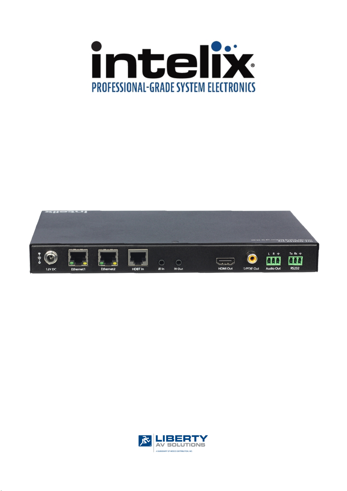
The INT-BSR4K-H2 is an HDMI 2.0 and HDCP 2.2 compliant HDBaseT scaling 4K receiver
that distributes uncompressed 4K@60Hz UHD video, digital coax / analog stereo audio,
Ethernet, RS232 and bi-direconal IR up to 100m/330 over a single category cable.
The INT-BSR4K-H2 can be controlled by telnet or RS232 but also can also store and pass
display commands via RS232 as well as generate CEC display ON and OFF commands.
The two-port network switch on the INT-BSR4K-H2 allows a second device to share the
100BaseT Ethernet pass-through connecon without adding addional hardware to the
installaon. The INT-BSR4K-H2 requires local power, however it can provide power to a
compable Intelix HDBaseT transmier.
The INT-BSR4K-H2 is compable with all Intelix HDBaseT product oerings and any
product that meets the HDBaseT specicaons.
Package Contents
• INT-BSR4K-H2 HDBaseT Scaling Receiver
• Quick Install Guide
• DC12V 3A power supply with US, UK, EU and AU power cords
• (1) IR Emier
• (1) IR Receiver
• (2) 3.5mm 3 pin phoenix male connectors
• (2) Mounng Brackets
5
Page 6
INT-BSR4K-H2 Owners Manual
11 12
Front and Rear Panel View
1
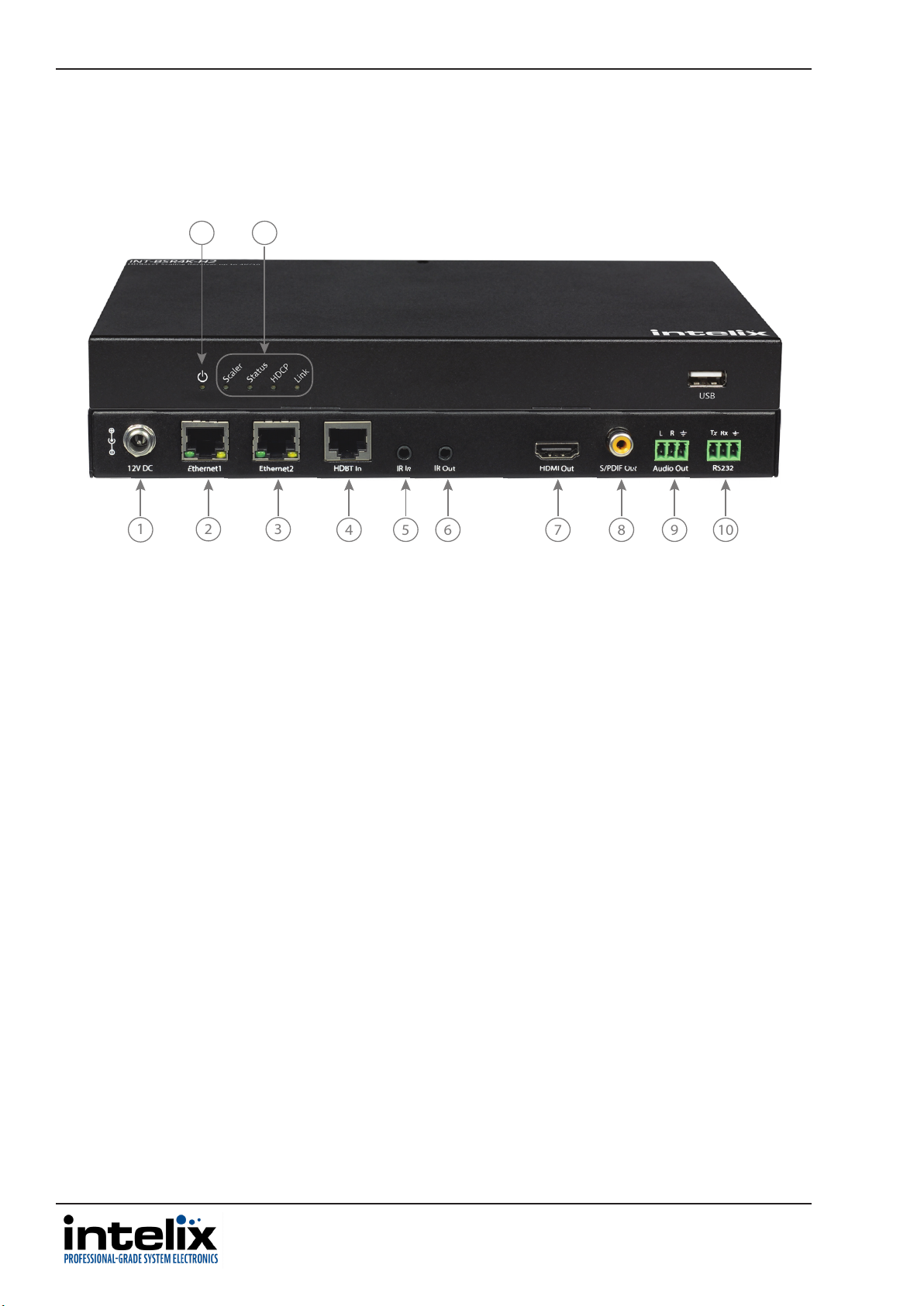
1. 12V DC - Locking power port to connect DC12V power adapter
2. ETHERNET 1 - Ethernet Port 1
3. ETHERNET 2 - Ethernet Port 2
4. HDBT IN - HDBaseT input to connect to HDBaseT output from transmier via category cable
5. IR IN - IR Input to connect to IR receiver
6. IR OUT - IR Output to connect to IR emier
7. HDMI OUT - HDMI output for display connecvity
8. S/PDIF OUT - Digital (S/PDIF) Coax Audio Output
9. AUDIO OUT - Analog Audio Output
10. RS232 - Serial control port for display control / 3rd party control
11. POWER STATUS LED - When solid, the transmier is receiving power
12. STATUS LEDS
• SCALER - When blinking slowly, the scalar chip is working properly
• STATUS - When blinking slowly, the transmier is working properly
• HDCP - When solid, HDCP content is being transmied; when blinking NON HDCP content is being
transmied; when o there is no audio or video data transmied
• LINK - When solid, the link between transmier and receiver is normal. When blinking or o the link
between transmier and receiver is not operable
2 3
4 5 6 7 8 9 10
6
Page 7

INT-BSR4K-H2 Owners Manual
Installaon Instrucons
Quick Start
1. Mount the switcher / extender set
2. Connect compable HDBaseT transmier
3. Connect display
4. Connect audio output (oponal)
5. Connect control (oponal)
6. Apply power
Mount the Switcher / Extender
At least 2 inches of free air space is required on both sides of the INT-BSR4K-H2 for proper side venlaon.
Avoid mounng the INT-BSR4K-H2 near a power amplier or any other source of signicant heat.
Aach the supplied mounng brackets to the sides of the receiver. Once the rails are installed the receiver can
be mounted in an A/V enclosure or on the wall behind a display or above a projector.
Connect Compable HDBaseT Transmier
Connect the INT-BSR4K-H2 HDBaseT receiver to a compable Intelix HDBaseT transmier using a Category
cable.
1 8
Twisted Pair Wiring
Use TIA/EIA-568B wiring for Category 6
connecon between the transmier and
receiver
To ensure proper performance of the INT-BSR4K-H2, it is recommended that you use solid
core shielded Category 6 F/UTP cabling at a minimum. Category 5e F/UTP may perform well
but may not support power over HDBaseT reliably.
When using shielded category cabling ALWAYS...
....use shielded connectors
....properly ground the category cable
Pin 1
Pin 2
Pin 3
Pin 4
Pin 5
Pin 6
Pin 7
Pin 8
TIA/EIA-568B
Orange/White
Green/White
Blue/White
Brown/White
Orange
Blue
Green
Brown
For opmized performance use the following Liberty Wire and Cable branded cabling;
Category 6 plenum; 24-4P-P-L6SH
Category 6A plenum; 24-4P-P-L6ASH
Category 6 NON-plenum; 24-4P-L6SH
Category 6A NON -plenum; 24-4P-L6ASH
7
Page 8

INT-BSR4K-H2 Owners Manual
Connecng a Display
HDMI Output
Connect the display devices to HDMI output on the receiver using an HDMI cable that is less than or equal to
5 meters in length.
Connect Audio Output
Insert the removable 3-pin phoenix connector block to the audio output. The INT-BSR4K-H2 supports a stereo
unbalanced output
AUDIO
SOURCE
L
R
INT-BSR4K-H2
L
R
Connecng Control
Connect the INT-BSR4K-H2 receivers LAN port to an Ethernet control network for telnet control.
Connect the DL-SE3H1V-C RS232 port on the receiver for serial control.
Note: The INT-BSR4K-H2 RS232 port can either be used with a control system for serial
control or can be connected to an external display for ON/OFF display control using
telnet control.
For complete list of control commands see pg11 RS232 and TCP/IP Control
RS232 Control Wiring
Connect the controller or device RX signal to TX port of the INT-BSR4K-H2 receiver. Then connect the controller or
device TX signal to the RX port on the INT-BSR4K-H2 receiver.
INT-BSR4K-H2
Tx
Rx
8
Controller or
Device
RXD
TXD
GND
Page 9

INT-BSR4K-H2 Owners Manual
Passing IR Signals
The INT-BSR4K-H2 is capable of passing IR signals between 33 and 55 KHz. To prevent damage to any of the electronics,
the extenders should be powered o while inserng or removing any IR components. Inserng an IR transmier into the
IR IN port may damage the IR circuit for that extender.
IR OUT: The IR transmier (IR emier) must be plugged into the IR OUT port.
IR IN: The IR receiver (IR eye) must be plugged into the IR IN port.
Apply Power
Plug the power supply into the power input port on the rear of the INT-BSR4K-H2 receiver Twist the locking ring
clockwise to prevent accidental disconnecon of power.
Note: The INT-BSR4K-H2 scaling receiver can provide power to a compable Intelix transmier via HDBaseT,
however a compable Intelix HDBaseT transmier (including HDBaseT matrix switchers) cannot provide power
to the INT-BSR4K-H2.
9
Page 10

INT-BSR4K-H2 Owners Manual
Applicaon Diagram
IR REMOTE 1
MEDIA PLAYER
Intelix INT-HDX100-TX
(NOT INCLUDED)
HDMI
CATx
AUDIO
RS232
IR
up to 100m / 330’
CONTROL SYSTEM
IR REMOTE 2
AUDIO AMP
PROJECTOR
10
Page 11

INT-BSR4K-H2 Owners Manual
RS232 and TCP/IP Control
RS232 Sengs: 115200 baud, 8 Data bits, 1 Stop bit, Parity = None
TCP/IP Sengs: User dened IP address (default IP address:192.168.2.128), port 23
The commands are case sensive All commands below are in ASCII and all strings and responses end in a
carriage return (hex 0D) and a line feed (hex 0A).
<CR> = Carriage return (Hex 0D)
<LF> = Line Feed (Hex 0A)
RS232 Mode Funcons
Descripon Command Example
Sets mode to scaler device control
CONNECT SCA Command:
CONNECT SCA<CR><LF>
Sets mode to HDBaseT pass-through
control (default)
Sets mode to upgrade device
Sets mode to enable RS232 control of
device through connected HDBaseT
transmier
Return:
CONNECT SCA<CR><LF>
CONNECT PTH Command:
CONNECT PTH<CR><LF>
Return:
CONNECT PTH<CR><LF>
CONNECT UPG Command:
CONNECT UPG<CR><LF>
Return:
CONNECT UPG<CR><LF>
CONNECT SML Command:
CONNECT SML<CR><LF>
Query current mode
Return:
CONNECT SML<CR><LF>
GET CONNECT Command:
GET CONNECT<CR><LF>
Return:
CONNECT SCA<CR><LF>
11
Page 12

INT-BSR4K-H2 Owners Manual
Output Scaler Sengs
Descripon Command Example
Set output resoluon
SET SCALER {r}
Command:
{r} = 3840x2160@60
3840x2160@50
3840x2160@30
3840x2160@25
3840x2160@24
1920x1200@60
1920x1080@60
1920x1080@50
1280x720@60
1280x720@50
1600x1200@60
1680x1050@60
1600x900@60
1440x900@60
1366x762@60
1360x768@60
1280x1024@60
1280x960@60
1280x768@60
1280@800@60
1024x768@60
800x600@60
AUTO
SET SCALER AUTO<CR><LF>
Return:
SCALER AUTO<CR><LF>
Query current output
resoluon seng
Note: AUTO setting copies
connected displays native
resolution setting for scaled
output
GET SCALER Command:
GET SCALER<CR><LF>
Return:
SCALER AUTO<CR><LF>
12
Page 13

EDID Input Sengs
Descripon Command Example
Set input EDID
SET EDID input {e}
Command:
INT-BSR4K-H2 Owners Manual
{e} = 3840x2160@30
1920x1200@60
1920x1080@60
1280x800@60
1280x720@60
1024x768@60
copy
Note: copy setting copies
connected displays native
EDID setting
SET EDID input copy<CR><LF>
Return:
EDID input copy<CR><LF>
CEC to Display Commands
Descripon Command Example
Display On / O via CEC
DISPLAY {p}
{p} = ON
OFF
Command:
DISPLAY ON<CR><LF>
Return:
DISPLAY ON<CR><LF>
Display Auto On or O via CEC with
acve source
Display Auto O with no source,
delay me (xx = 0-30 minutes)
DISPLAY AUTO {p}
{p} = ON
OFF
DISPLAY AUTO DELAY xx Command:
Command:
DISPLAY AUTO ON<CR><LF>
Return:
DISPLAY AUTO ON<CR><LF>
DISPLAY AUTO DELAY
1<CR><LF>
Return:
DISPLAY AUTO DELAY 1
MINUTES <CR><LF>
13
Page 14

INT-BSR4K-H2 Owners Manual
RS232 to Display Commands
Descripon Command Example
Set RS232 port to baud rate of
display
Set end character
SET BAUD {b}
{b} = 9600
57600
115200
SET ENCHAR {e}
Command:
SET BAUD 115200<CR><LF>
Return:
BAUD 115200<CR><LF>
Command:
Query end character
Set RS232 display on command -
ASCII format
Set RS232 display on command HEX format
{e} = cr
lf
crlf
null
GET ENCHAR Command:
DON xxxx
xxxx = ASCII display
ON command string
DON_HEX 0Xxx 0Xxx
0Xxx 0Xxx = HEX display
ON command string
SET ENDCHAR cr<CR><LF>
Return:
ENDCHAR cr<CR><LF>
GET ENDCHAR<CR><LF>
Return:
ENDCHAR CR<CR><LF>
Command:
DON PWR ON<CR><LF>
Return:
DON PWR ON<CR><LF>
Command:
DON 0XAA 0XBB<CR><LF>
Return:
Query RS232 display on command
14
DON AA BB<CR><LF>
DON? Command:
DON?<CR><LF>
Return:
DON PWR ON<CR><LF>
Page 15

RS232 to Display Commands (connued)
Descripon Command Example
Set RS232 display o command ASCII format
Set RS232 display o command -
HEX format
Get RS232 display o command
DOF xxxx
xxxx = ASCII display
OFF command string
DOF_HEX 0Xxx 0Xxx
0Xxx 0Xxx = HEX
display OFF command
string
DOF? Command:
Command:
DOF PWR OFF<CR><LF>
Return:
DOFF PWR OFF<CR><LF>
Command:
DOF 0X8F 0XBB<CR><LF>
Return:
DOF 8F BB<CR><LF>
INT-BSR4K-H2 Owners Manual
Set auto display power ON
Set auto display power OFF
Turn On / O display via RS232
DOF?<CR><LF>
Return:
DOF PWR OFF<CR><LF>
DFG1 Command:
DFG1<CR><LF>
Return:
ON<CR><LF>
DFG0 Command:
DFG0<CR><LF>
Return:
OFF<CR><LF>
DISP {p}
Command:
{p} = ON
OFF
DISP ON<CR><LF>
Return:
DISPLAY ON<CR><LF>
15
Page 16

INT-BSR4K-H2 Owners Manual
De-embedded Audio Output Sengs
Descripon Command Example
Set de-embedded audio output volume
(0-100)
Query de-embedded audio output
volume
SET VOL {v}
{v} = 0-100
GET VOL Command:
Command:
SET VOL 50<CR><LF>
Return:
VOL 50<CR><LF>
GET VOL<CR><LF>
Return:
VOL 50<CR><LF>
IP Addressing Commands
Descripon Command
Set Stac IP Address and Subnet
Get IP Address and Subnet
SET IPADDRESS STATIC ip4addr {ip} netmask
{n}
{ip} = ip address
{n} = subnet
Example
Command:
SET IPADDRESS STATIC ip4addr 192.168.2.128
netmask 255.255.255.0<CR><LF>
Return:
IPADDRESS STATIC ip4addr 192.168.2.128 netmask
255.255.255.0<CR><LF>
GET IPADDRESS
Command:
GET IPADDRESS<CR><LF>
16
Return:
IPADDRESS STATIC ip4addr 192.168.2.128
netmask 255.255.255.0<CR><LF>
Page 17

Miscellaneous Commands
Descripon Command Example
Get Current Firmware Version
Upgrade Device Firmware
Factory Reset
GET VER Command:
GET VER<CR><LF>
Return:
V1.7<CR><LF>
UPG Command:
UPG<CR><LF>
Return:
UPG<CR><LF>
RESET Command:
INT-BSR4K-H2 Owners Manual
System Reboot
RESET<CR><LF>
Return:
RESET<CR><LF>
REBOOT Command:
REBOOT<CR><LF>
Return:
REBOOT<CR><LF>
17
Page 18

INT-BSR4K-H2 Owners Manual
Video
Video Output (1) HDMI
Video Output Connector (1) HDMI type A
Output Video Signal HDMI
Output Resoluons Supported SMPTE: 4096 x 2160@24/30/60 (YUV4:2:0); 3840 x
Standards Compliant with HDMI 2.0 & HDCP2.2
Audio
Supported output formats Analog and Digital: PCM 2.0
Audio Outputs Stereo analog and digital coax
Audio Output Connectors Analog: (1) 3 Pin phoenix
Audio Output Impedance 70 Ohms
Frequency Response 20Hz~20K Hz
CONTROL
Control Port / Connector (2) LAN / RJ45
Other
System Bandwidth 9Gbps
Transmission Distance 1080p 100m / 330’ or less when using Cat6 F/UTP, 4K 70m
Technical Specicaons
2160@24/30/60 (YUV4:2:0); 1920 x 1080@60; 1280 x
720@60; 720 x 576p@60;
720 x 480p@60
VESA: 1920 x 1200@60; 1680 x 1050@60; 1600 x
1200@60; 1600 x 900@60; 1440 x 990@60; 1366 x
768@60@60; 1360 x 768@60; 1280 x 1024@60; 1280
x 960@60; 1280 x 800@60; 1280 x 768@60; 1024 x
768@60;
800 x 600@60
Digital: (1) Digital S/PDIF Coax
(1) RS232 / 3 pin phoenix
or less when using Cat6 F/UTP .
18
1080p 100m / 330’ or less when using Cat6A F/UTP, 4K
100m or less when using Cat6A F/UTP .
Operang Temperature 0 ~ +45 C (32 to + 113 °F)
Storage Temperature -20 to +70°C (-4 to + 158 °F)
Humidity 10% ~ 90%
Power Supply DC12V 3A
Power Consumpon 16.4w
Dimension (W*H*D) 234.4. mm x 25mm x 143mm
9.2” x 1” x 5.6”
Weight .9kg / 1.9 lbs
Warranty 2 years
Cercaon CE, FCC, RoHS
Page 19

Thank you for your purchase.
For Technical Support please call our toll free number at
800-530-8998 or email us at supportlibav@libav.com
www.libav.com
Intelix is a brand of:
11675 Ridgeline Drive
Colorado Springs, Colorado
80921 USA
Phone: 719-260-0061
Fax: 719-260-0075
Toll-Free: 800-530-8998
 Loading...